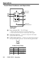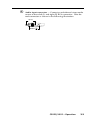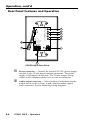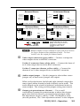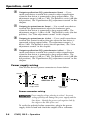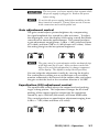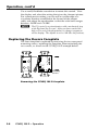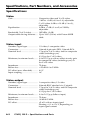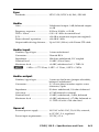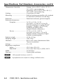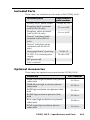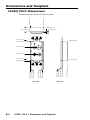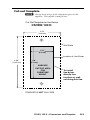
1
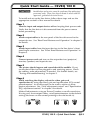
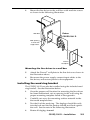
User’s Manual CSVEQ 100 D Composite Video and S-Video Line Driver with Audio Extron USA - West Headquarters +800.633.9876 Inside USA / Canada Only +1.714.491.1500 +1.714.491.1517 FAX Extron USA - East Extron Europe Extron Asia Extron Japan Extron China Extron Dubai +800.633.9876 +800.3987.6673 +800.7339.8766 Inside Europe Only Inside Asia Only +81.3.3511.7655 +81.3.3511.7656 FAX +400.883.1568 Inside USA / Canada Only +971.4.2991800 +971.4.2991880 FAX +1.919.863.1794 +1.919.863.1797 FAX +31.33.453.4040 +31.33.453.4050 FAX +65.6383.4400 +65.6383.4664 FAX © 2008 Extron Electronics. All rights reserved. Inside China Only +86.21.3760.1568 +86.21.3760.1566 FAX 68-1598-01 Rev. A 08 08 Precautions Safety Instructions • English This symbol is intended to alert the user of important operating and maintenance (servicing) instructions in the literature provided with the equipment. This symbol is intended to alert the user of the presence of uninsulated dangerous voltage within the product’s enclosure that may present a risk of electric shock. Caution Read Instructions • Read and understand all safety and operating instructions before using the equipment. Retain Instructions • The safety instructions should be kept for future reference. Follow Warnings • Follow all warnings and instructions marked on the equipment or in the user information. Avoid Attachments • Do not use tools or attachments that are not recommended by the equipment manufacturer because they may be hazardous. Consignes de Sécurité • Français Ce symbole sert à avertir l’utilisateur que la documentation fournie avec le matériel contient des instructions importantes concernant l’exploitation et la maintenance (réparation). Ce symbole sert à avertir l’utilisateur de la présence dans le boîtier de l’appareil de tensions dangereuses non isolées posant des risques d’électrocution. Attention Lire les instructions• Prendre connaissance de toutes les consignes de sécurité et d’exploitation avant d’utiliser le matériel. Conserver les instructions• Ranger les consignes de sécurité afin de pouvoir les consulter à l’avenir. Respecter les avertissements • Observer tous les avertissements et consignes marqués sur le matériel ou présentés dans la documentation utilisateur. Eviter les pièces de fixation • Ne pas utiliser de pièces de fixation ni d’outils non recommandés par le fabricant du matériel car cela risquerait de poser certains dangers. Sicherheitsanleitungen • Deutsch Dieses Symbol soll dem Benutzer in der im Lieferumfang enthaltenen Dokumentation besonders wichtige Hinweise zur Bedienung und Wartung (Instandhaltung) geben. Dieses Symbol soll den Benutzer darauf aufmerksam machen, daß im Inneren des Gehäuses dieses Produktes gefährliche Spannungen, die nicht isoliert sind und die einen elektrischen Schock verursachen können, herrschen. Achtung Lesen der Anleitungen • Bevor Sie das Gerät zum ersten Mal verwenden, sollten Sie alle Sicherheits-und Bedienungsanleitungen genau durchlesen und verstehen. Aufbewahren der Anleitungen • Die Hinweise zur elektrischen Sicherheit des Produktes sollten Sie aufbewahren, damit Sie im Bedarfsfall darauf zurückgreifen können. Befolgen der Warnhinweise • Befolgen Sie alle Warnhinweise und Anleitungen auf dem Gerät oder in der Benutzerdokumentation. Keine Zusatzgeräte • Verwenden Sie keine Werkzeuge oder Zusatzgeräte, die nicht ausdrücklich vom Hersteller empfohlen wurden, da diese eine Gefahrenquelle darstellen können. Instrucciones de seguridad • Español Este símbolo se utiliza para advertir al usuario sobre instrucciones importantes de operación y mantenimiento (o cambio de partes) que se desean destacar en el contenido de la documentación suministrada con los equipos. Este símbolo se utiliza para advertir al usuario sobre la presencia de elementos con voltaje peligroso sin protección aislante, que puedan encontrarse dentro de la caja o alojamiento del producto, y que puedan representar riesgo de electrocución. Precaucion Leer las instrucciones • Leer y analizar todas las instrucciones de operación y seguridad, antes de usar el equipo. Conservar las instrucciones • Conservar las instrucciones de seguridad para futura consulta. Obedecer las advertencias • Todas las advertencias e instrucciones marcadas en el equipo o en la documentación del usuario, deben ser obedecidas. Evitar el uso de accesorios • No usar herramientas o accesorios que no sean especificamente recomendados por el fabricante, ya que podrian implicar riesgos. Extron’s Warranty Warning Power sources • This equipment should be operated only from the power source indicated on the product. This equipment is intended to be used with a main power system with a grounded (neutral) conductor. The third (grounding) pin is a safety feature, do not attempt to bypass or disable it. Power disconnection • To remove power from the equipment safely, remove all power cords from the rear of the equipment, or the desktop power module (if detachable), or from the power source receptacle (wall plug). Power cord protection • Power cords should be routed so that they are not likely to be stepped on or pinched by items placed upon or against them. Servicing • Refer all servicing to qualified service personnel. There are no userserviceable parts inside. To prevent the risk of shock, do not attempt to service this equipment yourself because opening or removing covers may expose you to dangerous voltage or other hazards. Slots and openings • If the equipment has slots or holes in the enclosure, these are provided to prevent overheating of sensitive components inside. These openings must never be blocked by other objects. Lithium battery • There is a danger of explosion if battery is incorrectly replaced. Replace it only with the same or equivalent type recommended by the manufacturer. Dispose of used batteries according to the manufacturer’s instructions. Extron Electronics warrants this product against defects in materials and workmanship for a period of three years from the date of purchase. In the event of malfunction during the warranty period attributable directly to faulty workmanship and/or materials, Extron Electronics will, at its option, repair or replace said products or components, to whatever extent it shall deem necessary to restore said product to proper operating condition, provided that it is returned within the warranty period, with proof of purchase and description of malfunction to: USA, Canada, South America, and Central America: Extron Electronics 1001 East Ball Road Avertissement Alimentations• Ne faire fonctionner ce matériel qu’avec la source d’alimentation indiquée sur l’appareil. Ce matériel doit être utilisé avec une alimentation principale comportant un fil de terre (neutre). Le troisième contact (de mise à la terre) constitue un dispositif de sécurité : n’essayez pas de la contourner ni de la désactiver. Déconnexion de l’alimentation• Pour mettre le matériel hors tension sans danger, déconnectez tous les cordons d’alimentation de l’arrière de l’appareil ou du module d’alimentation de bureau (s’il est amovible) ou encore de la prise secteur. Protection du cordon d’alimentation • Acheminer les cordons d’alimentation de manière à ce que personne ne risque de marcher dessus et à ce qu’ils ne soient pas écrasés ou pincés par des objets. Réparation-maintenance • Faire exécuter toutes les interventions de réparationmaintenance par un technicien qualifié. Aucun des éléments internes ne peut être réparé par l’utilisateur. Afin d’éviter tout danger d’électrocution, l’utilisateur ne doit pas essayer de procéder lui-même à ces opérations car l’ouverture ou le retrait des couvercles risquent de l’exposer à de hautes tensions et autres dangers. Fentes et orifices • Si le boîtier de l’appareil comporte des fentes ou des orifices, ceux-ci servent à empêcher les composants internes sensibles de surchauffer. Ces ouvertures ne doivent jamais être bloquées par des objets. Lithium Batterie • Il a danger d’explosion s’ll y a remplacment incorrect de la batterie. Remplacer uniquement avec une batterie du meme type ou d’un ype equivalent recommande par le constructeur. Mettre au reut les batteries usagees conformement aux instructions du fabricant. Vorsicht Stromquellen • Dieses Gerät sollte nur über die auf dem Produkt angegebene Stromquelle betrieben werden. Dieses Gerät wurde für eine Verwendung mit einer Hauptstromleitung mit einem geerdeten (neutralen) Leiter konzipiert. Der dritte Kontakt ist für einen Erdanschluß, und stellt eine Sicherheitsfunktion dar. Diese sollte nicht umgangen oder außer Betrieb gesetzt werden. Stromunterbrechung • Um das Gerät auf sichere Weise vom Netz zu trennen, sollten Sie alle Netzkabel aus der Rückseite des Gerätes, aus der externen Stomversorgung (falls dies möglich ist) oder aus der Wandsteckdose ziehen. Schutz des Netzkabels • Netzkabel sollten stets so verlegt werden, daß sie nicht im Weg liegen und niemand darauf treten kann oder Objekte darauf- oder unmittelbar dagegengestellt werden können. Wartung • Alle Wartungsmaßnahmen sollten nur von qualifiziertem Servicepersonal durchgeführt werden. Die internen Komponenten des Gerätes sind wartungsfrei. Zur Vermeidung eines elektrischen Schocks versuchen Sie in keinem Fall, dieses Gerät selbst öffnen, da beim Entfernen der Abdeckungen die Gefahr eines elektrischen Schlags und/oder andere Gefahren bestehen. Schlitze und Öffnungen • Wenn das Gerät Schlitze oder Löcher im Gehäuse aufweist, dienen diese zur Vermeidung einer Überhitzung der empfindlichen Teile im Inneren. Diese Öffnungen dürfen niemals von anderen Objekten blockiert werden. Litium-Batterie • Explosionsgefahr, falls die Batterie nicht richtig ersetzt wird. Ersetzen Sie verbrauchte Batterien nur durch den gleichen oder einen vergleichbaren Batterietyp, der auch vom Hersteller empfohlen wird. Entsorgen Sie verbrauchte Batterien bitte gemäß den Herstelleranweisungen. Advertencia Alimentación eléctrica • Este equipo debe conectarse únicamente a la fuente/tipo de alimentación eléctrica indicada en el mismo. La alimentación eléctrica de este equipo debe provenir de un sistema de distribución general con conductor neutro a tierra. La tercera pata (puesta a tierra) es una medida de seguridad, no puentearia ni eliminaria. Desconexión de alimentación eléctrica • Para desconectar con seguridad la acometida de alimentación eléctrica al equipo, desenchufar todos los cables de alimentación en el panel trasero del equipo, o desenchufar el módulo de alimentación (si fuera independiente), o desenchufar el cable del receptáculo de la pared. Protección del cables de alimentación • Los cables de alimentación eléctrica se deben instalar en lugares donde no sean pisados ni apretados por objetos que se puedan apoyar sobre ellos. Reparaciones/mantenimiento • Solicitar siempre los servicios técnicos de personal calificado. En el interior no hay partes a las que el usuario deba acceder. Para evitar riesgo de electrocución, no intentar personalmente la reparación/mantenimiento de este equipo, ya que al abrir o extraer las tapas puede quedar expuesto a voltajes peligrosos u otros riesgos. Ranuras y aberturas • Si el equipo posee ranuras o orificios en su caja/alojamiento, es para evitar el sobrecalientamiento de componentes internos sensibles. Estas aberturas nunca se deben obstruir con otros objetos. Batería de litio • Existe riesgo de explosión si esta batería se coloca en la posición incorrecta. Cambiar esta batería únicamente con el mismo tipo (o su equivalente) recomendado por el fabricante. Desachar las baterías usadas siguiendo las instrucciones del fabricante. Anaheim, CA 92805, USA Asia: Extron Electronics, Asia 135 Joo Seng Road, #04-01 PM Industrial Bldg. Singapore 368363 Europe, Africa, and the Middle East: Extron Electronics, Europe Beeldschermweg 6C 3821 AH Amersfoort The Netherlands Japan: Extron Electronics, Japan Kyodo Building 16 Ichibancho Chiyoda-ku, Tokyo 102-0082 Japan This Limited Warranty does not apply if the fault has been caused by misuse, improper handling care, electrical or mechanical abuse, abnormal operating conditions or nonExtron authorized modification to the product. If it has been determined that the product is defective, please call Extron and ask for an Applications Engineer at (714) 491-1500 (USA), 31.33.453.4040 (Europe), 65.6383.4400 (Asia), or 81.3.3511.7655 (Japan) to receive an RA# (Return Authorization number). This will begin the repair process as quickly as possible. Units must be returned insured, with shipping charges prepaid. If not insured, you assume the risk of loss or damage during shipment. Returned units must include the serial number and a description of the problem, as well as the name of the person to contact in case there are any questions. Extron Electronics makes no further warranties either expressed or implied with respect to the product and its quality, performance, merchantability, or fitness for any particular use. In no event will Extron Electronics be liable for direct, indirect, or consequential damages resulting from any defect in this product even if Extron Electronics has been advised of such damage. Please note that laws vary from state to state and country to country, and that some provisions of this warranty may not apply to you. 安全须知 • 中文 警告 这个符号提示用户该设备用户手册中 有重要的操作和维护说明。 电源 • 该 设 备 只 能 使 用 产 品 上 标 明 的 电 源 。 设 备 必须使用有地线的供电系统供电。 第三条线 (地线)是安全设施,不能不用或跳过。 这个符号警告用户该设备机壳内有暴 拔掉电源 • 为安全地从设备拔掉电源,请拔掉所有设备后 或桌面电源的电源线,或任何接到市电系统的电源线。 露的危险电压,有触电危险。 电源线保护 • 妥善布线, 避免被踩踏,或重物挤压。 注意 阅读说明书 • 用 户 使 用 该 设 备 前 必 须 阅 读 并 理 解所有安全和使用说明。 保存说明书 • 用户应保存安全说明书以备将来使 用。 遵守警告 • 用户应遵守产品和用户指南上的所有安 全和操作说明。 维护 • 所有维修必须由认证的维修人员进行。 设备内部 没有用户可以更换的零件。为避免出现触电危险不要自 己试图打开设备盖子维修该设备。 通风孔 • 有些设备机壳上有通风槽或孔,它们是用来防止 机内敏感元件过热。 不要用任何东西挡住通风孔。 锂电池 • 不正确的更换电池会有爆炸的危险。 必须使用 与厂家推荐的相同或相近型号的电池。 按照生产厂的 建议处理废弃电池。 避免追加 • 不要使用该产品厂商没有推荐的工具或 追加设备,以避免危险。 FCC Class A Notice This equipment has been tested and found to comply with the limits for a Class A digital device, pursuant to part 15 of the FCC Rules. Operation is subject to the following two conditions: (1) this device may not cause harmful interference, and (2) this device must accept any interference received, including interference that may cause undesired operation. The Class A limits are designed to provide reasonable protection against harmful interference when the equipment is operated in a commercial environment. This equipment generates, uses, and can radiate radio frequency energy and, if not installed and used in accordance with the instruction manual, may cause harmful interference to radio communications. Operation of this equipment in a residential area is likely to cause harmful interference, in which case the user will be required to correct the interference at his own expense. N This unit was tested with shielded cables on the peripheral devices. Shielded cables must be used with the unit to ensure compliance with FCC emissions limits. Quick Start Guide — CSVEQ 100 D C Installation and service must be performed by authorized personnel only. These line drivers must be used with UL approved, grounded electrical boxes. To install and set up the line driver, follow these steps and see the appropriate sections of this manual for details. Step 1 Turn the input and output devices off and unplug their power cords. Verify that the line driver is disconnected from the power source before proceeding. Step 2 Attach output cables to the rear panel of the line driver and to the output devices. See "Rear Panel Features and Operation" in chapter 3 for details. Step 3 Attach input cables from the input devices to the line driver’s front panel input connectors. See "Front Panel Features and Operation" in chapter 3. Step 4 Connect power cords and turn on the output devices (projector/ monitor, speakers) and input devices. Step 5 The picture should appear and sound should be audible. If not, ensure that all devices are plugged in and receiving power. Check the cabling, make adjustments as needed. For further details, see "Testing and troubleshooting" in chapter 2. Step 6 While watching the display, adjust the video gain and equalization by using the rotary gain and equalization (EQ) control potentiometers. An oscilloscope can be used to achieve a more precise adjustment. See “Gain adjustment control" and "Equalization (EQ) adjustment control” in chapter 3 for details. Make all adjustments using an Extron Tweeker or small screwdriver. If using very short output cables, set all potentiometers to the default setting (the arrow on the control pointing to the dot beside it). CSVEQ 100 D • Quick Start Guide QS-1 Quick Start — CSVEQ 100 D, cont’d When using long cables, follow these steps: a. Supply the color bars test signal to the input. (Recommendation: use an Extron VTG 300 Video Test Generator to generate the test signal.) b. Adjust the Gain control(s) for the output until the signal level at the far end is the same as the input (or the display shows the correct brightness and contrast). c. Adjust the EQ control for the output so that no overshoot or round front corner appears at the far end on the oscilloscope or you see a sharp picture with no smearing. Step 7 See "Installation Instructions" in chapter 2 for further installation details. QS-2 CSVEQ 100 D • Quick Start Guide Table of Contents Chapter One • Introduction ................................................... 1-1 About this Manual..................................................................... 1-2 Features......................................................................................... 1-2 Chapter Two • Installation ...................................................... 2-1 Application Example................................................................. 2-2 Installing the CSVEQ 100 D..................................................... 2-3 Preparing the site and installing the wall box..................... 2-3 Mounting the line driver........................................................ 2-4 Installing the mud ring bracket............................................. 2-5 Testing and troubleshooting.................................................. 2-7 If the image does not appear or there is no sound..............2-7 If the image is not displayed correctly...................................2-7 Chapter Three • Operation ..................................................... 3-1 Front Panel Features and Operation.................................... 3-2 Rear Panel Features and Operation..................................... 3-4 Power supply wiring............................................................... 3-6 Gain adjustment control......................................................... 3-7 Equalization (EQ) adjustment control................................... 3-7 Replacing the Decora Faceplate............................................ 3-8 Appendix A • Specifications, Part Numbers, and Accessories .........................................................................................A-1 Specifications...............................................................................A-2 Included Parts..............................................................................A-5 Optional Accessories.................................................................A-5 Appendix B • Dimensions and Template ...................... B-1 CSVEQ 100 D Dimensions........................................................ B-2 Cut-out Template........................................................................ B-3 All trademarks mentioned in this manual are the properties of their respective owners. 68-1598-01 Rev. A 08 08 CSVEQ 100 D • Table of Contents TOC-i Table of Contents, cont’d TOC-ii CSVEQ 100 D • Table of Contents CSVEQ 100 D 1 Chapter One Introduction About this Manual Features Introduction About this Manual The CSVEQ 100 D is a high performance composite video, S-video, and audio line driver designed to compensate for signal attenuation and high frequency loss encountered during long cable runs. It is capable of simultaneously driving composite video and S-video plus audio signals up to 1000 feet (300 m) on Extron MHR or RG59 high resolution video cables and STP series audio cables. The CSVEQ 100 D mounts in a Decora® style wallplate and is ideal for use in residential and commercial environments where video and audio signals need to be extended over a long distance. Features Long distance line driving — Drives composite video or S-video signals up to 1000 feet (300 meters) using Extron's MHR cable. Balanced or unbalanced stereo or dual mono output — Unbalanced stereo audio input can be output as balanced or unbalanced stereo audio or as dual mono. Video gain adjustment — Offers a video gain adjustment for composite video and Y of S-video with a range of -1 dB to +3 dB, and C of S-video with a range of 0 dB to +10 dB. Equalization adjustment — Features an equalization adjustment range of 0 dB to +7 dB at 5 MHz that changes the level and peaking of the output signal to compensate for use of long cables. Stereo or dual mono output jumper — A rear panel jumper selects between stereo and dual mono output formats. Front panel LED indicator — Indicates when the line driver is receiving power or a video signal. Compatibility — Compatible with NTSC, PAL, and SECAM 1-2 CSVEQ 100 D • Introduction CSVEQ 100 D 2 Chapter Two Installation Application Examples Installing the CSVEQ 100 D Installation Application Example To get started, refer to the "Quick Start Guide" at the beginning of this manual. C Installation and service must be performed by authorized personnel only. Extron MPA 122 Extron SI 26X Mini Power Amplifier Two-way Ceiling Speakers Balanced Audio Extron CSVEQ 100 D S-Video Projector Composite Video O IN IDE EO S-V IN VID Composite Video, S-Video, and Audio Line Driver 1,000 Feet IO UD A L - IN -R DVD/VCR Combo CSVEQ 100 D application example 2-2 CSVEQ 100 D • Installation Installing the CSVEQ 100 D The CSVEQ 100 D is a wall-mounted product and can be mounted into an electrical wall box. This section includes site preparation, wall box installation, and the mounting of the line driver in the wall box. N The line driver must be installed into an Underwriters Laboratories (UL) approved electrical wall box. The box is not included with the line driver; the installer is responsible for obtaining and installing the box. Preparing the site and installing the wall box Choose a location that allows cable runs without interference. Allow enough depth for both the wall box and the cables. You may need to install the cables into the wall or conduits before installing the line driver. The line driver can be installed in a standard one-gang electrical wall box. The installation must conform to national and local electrical codes. A dimensional drawing and a cutout template of the line driver are provided in appendix B of this manual. N The cutout template shown in appendix B is not full size. Pay attention to the measurements shown on the template. 1. Mark the guidelines for the opening on the wall. • If the line driver is to be installed in a wall box, place the box against the installation surface and draw a line on it around the outside of the box. • If the line driver is to be installed without a wall box (fastening it directly to the wall), measure and mark the surface for the cutout area indicated in the cutout template. 2. Cut out the material from the marked area. 3. Check the opening size by inserting the wall box (if used) or the line driver (if no box is used) into the opening. The box and line driver should fit easily into the opening. Enlarge or smooth the edges of the opening if needed. 4. Feed cables through the wall box punch-out holes, and secure them with cable clamps to provide strain relief. 5. Insert the wall box into the opening, and attach it to the wall or stud using nails or screws. The front edge should be flush with the outer wall surface. See the following illustration. CSVEQ 100 D • Installation 2-3 Installation, cont’d Wall Stud Installation Cable Wall Stud Installation Cable Cable Clamp Cable Clamp Screws or Nails Screws or Nails Attaching the wall box to a wall stud If attaching the wall box to wood, use four #8 or #10 screws or 10-penny nails. A minimum of ½" (1.3 cm) of screw threads must penetrate the wood. If attaching the wall box to metal studs, use four #8 or #10 self-tapping sheet metal screws or machine bolts with matching nuts. Mounting the line driver Before mounting the line driver and if it has not already been tested, test the system to make sure that the connections and settings are correct. See "Testing and troubleshooting" in this chapter. If the system is operating correctly, the line driver can be installed in the wall. Adjust the gain and equalization, and set the Audio Out switch to Stereo or Dual Mono before fastening the line driver into the wall box. The controls and cables will be inaccessible after installation. See “Rear Panel Features and Operation" in chapter 3 for details about settings and adjustments. Continue mounting the line driver by following the steps below. 2-4 1. Remove power from the line driver by disconnecting the power supply from the AC source. 2. Connect the output cables to the rear of the device. 3. Place the line driver through the opening in the wall and into the wall box. Take care not to damage the output cable(s), which fit behind the line driver at the back of the wall box. CSVEQ 100 D • Installation 4. Mount the line driver to the wall box with machine screws as shown in the following illustration. Extron CSVEQ 100 D Wall Box O DE S-VI IN O IN VIDE Wall opening is flush with edge of box. DIO AU IN R L Decora Faceplate Mounting the line driver to a wall box 5. Attach the Decora® wall plate to the line driver as shown in the illustration above. 6. Reconnect the power supply, connect input cables to the line driver, and restore power to the equipment. Installing the mud ring bracket The CSVEQ 100 D can also be installed using the included mud ring bracket. See the illustration below. 1. Once the proper wall location for mounting the line driver has been determined, cut an opening in the wall using the proper mounting template found in the appendix. 2. Carefully cut away the mounting surface material inside the traced template lines 3. Test the fit of the mud ring. The doglegs should fit easily into the hole and the flat portion should rest flush against the wall. See the note in the following illustration. 4. Rotate all doglegs inward. CSVEQ 100 D • Installation 2-5 Installation, cont’d 5. Insert the mud ring into the hole. 6. Tighten all of the dogleg screws until the doglegs clamp the mud ring to the mounting surface. Do not overtighten. Standard mud rings only: If you are going to screw the mud ring to the surface, rather than using the detachable doglegs, mark the four surface mounting screw holes at the corners of the mud ring. Wall Extron Wall Mounting Bracket Extron CSVEQ 100 D O DE S-VIIN O IN VIDE DIO AU IN R L Decora Faceplate Installation using a mud ring 2-6 CSVEQ 100 D • Installation Testing and troubleshooting 1. Apply power to the line driver. The power/signal LED on the line driver lights amber (power) or green (video input). 2. If the LED does not light, check the wiring at both the line driver and the power supply, and make sure the power supply is connected to a power source. If the image does not appear or there is no sound 1. Make sure that all the devices are powered on. 2. Ensure that the connectors are wired correctly at both ends of the cables. Audio cables must be wired for an unbalanced stereo input signal and for the appropriate (unbalanced or balanced) output signal. 3. Check the video source’s user’s guide or contact Extron to determine if there are special requirements to output video to the external video port. 4. Call the Extron S3 Sales and Technical Support Hotline if the image still does not appear or there is no sound. If the image is not displayed correctly 1. If the picture is too bright or too dark, or if the edges of the image seem to exceed their boundaries, or if thin lines and sharp edges look thick and fuzzy, change the gain setting. If the picture appears and is stable, but it has ghosting or blooming, verify that the video input is properly terminated. If the problem is not resolved by changing the termination, try using a different input cable. Poor quality or damaged cable can cause ghosting and blooming. 2. If the picture still is not displayed correctly, call the Extron S3 Sales and Technical Support Hotline. CSVEQ 100 D • Installation 2-7 Installation, cont’d 2-8 CSVEQ 100 D • Installation CSVEQ 100 D 3 Chapter Three Operation Front Panel Features and Operation Rear Panel Features and Operation Replacing the Decora Faceplate Operation Front Panel Features and Operation Wall Plate Faceplate 1 S-VIDEO IN VIDEO IN 3 2 AUDIO IN R L 4 Wall Plate Mounting Screw CSVEQ 100 D Front Panel a b c Power indicator LED — This LED lights: • Amber when the line driver is receiving full power • Green when the line driver is receiving a video signal Video input connector — Connect a composite video input source to this RCA connector. S-video input connector — Connect an S-video input source to this 4-pin mini DIN connector. See the following pinout table. 3 1 4 2 S-video Pinout Table 3-2 PIN NAME DESCRIPTION 1 GND Ground (Y) 2 GND Ground (C) 3 Y Luminance 4 C Chrominance CSVEQ 100 D • Operation d Audio input connectors — Connect an unbalanced stereo audio source to these left (L) and right (R) RCA connectors. Wire the male connector as shown in the following illustration. Tip (+) Sleeve ( ) CSVEQ 100 D • Operation 3-3 Operation, cont’d C GAIN Y GAIN 6 7 GAIN VIDEO VIDEO OUTPUT 4 AUDIO OUTPUT CONFIG JUMPER POSITION OFF = DUAL MONO ON = STEREO 5 8 EQ CSVEQ 100 D EQ Rear Panel Features and Operation 9 AUDIO OUTPUT 3 1 2 CSVEQ 100 D Rear Panel a b 3-4 Power connector — Connect the external 12 VDC power supply into this 2-pin, 3.5 mm direct insertion connector. The power supply is included with the unit. The "Power supply wiring" section in this chapter explains how to wire the connector. Audio output connector — Wire a balanced/unbalanced audio output device to this 3.5 mm, 5-pole, direct insertion captive screw connector. See the following wiring diagrams. CSVEQ 100 D • Operation Balanced Stereo Left Tip (+) Left Ring (-) Sleeve (s) Right Tip (+) Right Ring (-) Unbalanced Stereo Left Tip (+) AUDIO OUTPUT CONFIG JUMPER POSITION OFF = DUAL MONO ON = STEREO Sleeve Right Tip (+) AUDIO OUTPUT CONFIG JUMPER POSITION OFF = DUAL MONO ON = STEREO Set Audio Output jumper to Stereo. Set Audio Output jumper to Stereo. Balanced Mono Unbalanced Mono Use either the left or the right channel. Use either the left or the right channel. Tip (+) Ring (-) Sleeve Tip (+) AUDIO OUTPUT CONFIG JUMPER POSITION OFF = DUAL MONO ON = STEREO Set Audio Output jumper to Dual Mono. Sleeve AUDIO OUTPUT CONFIG JUMPER POSITION OFF = DUAL MONO ON = STEREO Set Audio Output jumper to Dual Mono. CAUTION Connect the sleeve to ground Do not tin the wires! (Gnd). Connecting the sleeve to a negative (–) terminal will damage the audio output circuits. N Balanced audio is more resistant to noise and can be driven for longer distances than unbalanced audio. For best results, wire the output for balanced audio. c Video output connector (green cable) — Connect a composite video output device to the BNC connector. S-video Y connector (luma, white cable) — Connect the luma of an S-video output device to the BNC connector. S-video C connector (chroma, yellow cable) — Connect the chroma of an S-video output device to the BNC connector. d Audio output jumper — Set this jumper to select either stereo (jumper on) or dual mono (jumper off) output. When set for dual mono, the left and right channels output the same signal (either channel or both channels can be used). The audio output can be wired for balanced/unbalanced mono or stereo output. The wiring and the jumper setting must match. e Output gain potentiometer (chroma) — Use a small screwdriver to rotate this potentiometer to adjust the chroma gain when the line driver is connected to long output cables. The adjustment range is 0 dB to +10 dB. The default is unity (the dot position). See "Gain adjustment control" in this chapter. CSVEQ 100 D • Operation 3-5 Operation, cont’d f g h i Output equalization (EQ) potentiometer (luma) — Use a small screwdriver to rotate this control to adjust equalization when the line driver is connected to long output cables. The adjustment range is 0 dB to +7 dB. The default is set to 0 dB (the dot position). See "Equalization (EQ) adjustment control" in this chapter. Output gain potentiometer (luma) — Use a small screwdriver to rotate this potentiometer to adjust the luminance gain when the line driver is connected to long output cables. The adjustment range is -1 dB to +3 dB. The default is unity (the dot position). See "Gain adjustment control" in this chapter. Output gain potentiometer (video) — Use a small screwdriver to rotate this control to adjust the gain when the line driver is connected to long output cables. The adjustment range is -1 dB to +3 dB. The default is unity (the dot position). See "Gain adjustment control" in this chapter. Output equalization (EQ) potentiometer (video) — Use a small screwdriver to rotate this control to adjust equalization when the line driver is connected to long output cables. The adjustment range is 0 dB to +7 dB. The default is set to 0 dB (the dot position). See "Equalization (EQ) adjustment control" in this chapter. Power supply wiring Wire the line driver's power connector as shown below. Smooth A Ridges A 3 SECTION A–A Power Supply Output Cord 5 Captive Screw Connector Power connector wiring C Power supply voltage polarity is critical. Incorrect voltage polarity can damage the power supply and the line driver. Identify the power cord negative lead by the ridges on the side of the cord. To verify the polarity before connection, plug in the power supply with no load and check the output with a voltmeter. 3-6 CSVEQ 100 D • Operation W The two power cord wires must be kept separate while the power supply is plugged in. Remove the power before wiring. N Do not tin the power supply leads before installing in the direct insertion connector. Tinned wires are not as secure in the connectors and could be pulled out. Gain adjustment control The gain control adjusts picture brightness by compensating for signal amplitude loss caused by cable resistance. To adjust the output gain, view the display while using a small, flat-blade screwdriver to rotate the potentiometer. This control produces a gain adjustment ranging from -1 dB to + 3 dB (video and luma of S-video) and from 0 dB to +10 dB (chroma of S-video). Select the setting that gives the best picture brightness. N The gain control is a potentiometer with a mechanical stop at the high and the low end. After you have reached the high or low end of the adjustment, no change is apparent on the display. The default is unity (the dot position) You can judge the adjustment visually by viewing the display. For a more precise setting use an oscilloscope or a waveform monitor connected to the far end of the output cable, and adjust the gain so that the level at the waveform monitor is 100 IRE. Equalization (EQ) adjustment control The equalization control adjusts the output level and peaking to get a sharp picture. This adjustment changes the level and peaking of the output signal to compensate for capacitance caused by up to 1000 feet (300 meters) of Extron MHR cable. This control produces an equalization adjustment ranging from 0 dB to + 7 dB (video and luma of S-video). CSVEQ 100 D • Operation 3-7 Operation, cont’d Use a small, flat-blade screwdriver to rotate this control. View the display and select the setting that gives the sharpest picture. For a more precise setting, you can use an oscilloscope or a waveform monitor connected to the far end of the output cable, and adjust the equalization so that the color burst ranges between -20 IRE and +20 IRE. N The EQ control is a potentiometer with a mechanical stop at the high and the low end. After you have reached the high or low end of the adjustment, no change is apparent on the display. The default is set to 0 dB (the dot position). Replacing the Decora Faceplate Y GAIN GAIN VIDEO AUDIO OUTPUT CONFIG JUMPER POSITION OFF = DUAL MONO ON = STEREO EQ VIDEO OUTPUT EQ C CSVEQ 100 D GAIN The front faceplate is replaced by removing the two rear panel mounting screws, replacing the faceplate, then reattaching the two screws, as shown in the CSVEQ 100 D example below. AUDIO OUTPUT Mounting Screws Faceplate (rear) Removing the CSVEQ 100 D faceplate 3-8 CSVEQ 100 D • Operation CSVEQ 100 D A Appendix A Specifications, Part Numbers, and Accessories Specifications Included Parts Optional Accessories Specifications, Part Numbers, and Accessories Specifications Video Gain������������������������������������������������� Composite video and Y of S-video: -1 dB to +3 dB (x0.9 to x1.4), adjustable C of S-video: 0 dB to +10 dB (x1 to x3), adjustable Equalization����������������������������������� 0 dB to +7 dB (x1 to x2) at 5 MHz, adjustable Bandwidth (Y of S-video)������������� 185 MHz (-3 dB) Output cable driving distance����� Up to 1000' (300 m) with Extron MHR cable Video input Number/signal type��������������������� 1 S-video, 1 composite video Connectors������������������������������������� 1 female 4-pin mini DIN, 1 female RCA Nominal level�������������������������������� 1 Vp-p for Y of S-video, and for composite video (including sync) 0.3 Vp-p for C of S-video Minimum/maximum levels�������� 0.4 to 2.0 Vp-p with no offset at unity gain for composite video (including sync) or for Y of S-video Impedance�������������������������������������� 75 ohms Return loss�������������������������������������� <-25 dB @ 0 to 5 MHz DC offset (max. allowable)���������� 4.0 V Input coupling������������������������������� AC Video output Number/signal type��������������������� 1 composite video, 1 S-video Connectors������������������������������������� 3 female BNC attached via 4" pigtails Nominal level�������������������������������� 1 Vp-p for Y of S-video, and for composite video (including sync) 0.3 Vp-p for C of S-video Minimum/maximum levels�������� 0.4 to 2.0 Vp-p (follows input) Impedance�������������������������������������� 75 ohms Return loss�������������������������������������� -30 dB @ 5 MHz DC offset����������������������������������������� ±5 mV with no input signal Floating: +0.1 to -0.6 V, depending on input signal content A-2 CSVEQ 100 D • Specifications and Parts Sync Standards���������������������������������������� NTSC 3.58, NTSC 4.43, PAL, SECAM Audio Gain������������������������������������������������� Unbalanced output: 0 dB; balanced output: +6 dB Frequency response���������������������� 20 Hz to 20 kHz, ±0.5 dB THD + Noise���������������������������������� 0.03% @ 1 kHz at nominal level S/N�������������������������������������������������� >90 dB at maximum output (unweighted) Stereo channel separation������������ >80 dB @ 1 kHz Output cable driving distance����� Up to 1000' (300 m) with Extron STP cable Audio input Number/signal type��������������������� 1 stereo unbalanced Connectors������������������������������������� 2 female RCA Impedance�������������������������������������� 18k ohms unbalanced, DC coupled Nominal level�������������������������������� -10 dBV (316 mVrms) Maximum level������������������������������ +8 dBV, unbalanced at 1% THD+N N 0 dBu = 0.775 Vrms, 0 dBV = 1 Vrms, 0 dBV ≈ 2 dBu Audio output Number/signal type��������������������� 1 stereo or dual mono (jumper-selectable), balanced/unbalanced Connectors������������������������������������� (1) 3.5 mm direct insertion captive screw connector, 5 pole Impedance�������������������������������������� 50 ohms unbalanced, 100 ohms balanced Gain error��������������������������������������� ±0.5 dB channel to channel Nominal level�������������������������������� -10 dBV, unbalanced; -2 dBu, balanced Maximum level ����������������������������� +9 dBV, unbalanced; +17 dBu, balanced at 1% THD+N with a 10k ohm load General External power supply����������������� 100 VAC to 240 VAC, 50/60 Hz, external; to 12 VDC, 2 A, regulated Power input requirements����������� 12 VDC, 0.2 A CSVEQ 100 D • Specifications and Parts A-3 Specifications, Part Numbers, Accessories, cont’d Temperature/humidity���������������� Storage: -40 to +158 °F (-40 to +70 °C) / 10% to 90%, noncondensing Operating: +32 to +122 °F (0 to +50 °C) / 10% to 90%, noncondensing Cooling������������������������������������������� Convection, no vents Mounting���������������������������������������� Wall or furniture mountable with standard US electrical wall boxes or mud rings Enclosure���������������������������������������� Metal rear enclosure, plastic faceplate Enclosure dimensions Faceplate����������������������������� 2.6" H x 1.3" W x 0.1" D (6.6 cm H* x 3.3 cm W x 0.3 cm D) (Fits the opening in a 1 gang Decora® faceplate. *Height is 3.8" [9.5 cm], including mounting tabs.) (Depth excludes connectors.) Device��������������������������������� 2.7" H x 1.8" W x 0.75" D (6.9 cm H x 4.6 cm W x 1.9 cm D) (Depth excludes connectors; height excludes mounting tabs.) Product weight������������������������������ 0.2 lbs (0.1 kg) Shipping weight���������������������������� 2 lbs (1 kg) Vibration����������������������������������������� ISTA 1A in carton (International Safe Transit Association) Listings������������������������������������������� UL, CUL Regulatory compliance Safety����������������������������������� CE, C-tick, CUL, UL EMI/EMC�������������������������� CE, C-tick, FCC Class A, ICES, VCCI MTBF����������������������������������������������� 30,000 hours Warranty����������������������������������������� 3 years parts and labor N All nominal levels are at ±10%. N Specifications are subject to change without notice. A-4 CSVEQ 100 D • Specifications and Parts Included Parts These items are included in each order of the CSVEQ 100 D. Included parts CSVEQ 100 D (black, white) Replacement part number 60-951-02, -03 Faceplate, black (included with 60-951-02 only) 21-xxx-0xLF Faceplate, white (included with 60-951-03 only) 21-xxx--0xLF ® Decora wall plate, black included with 60-951-02 only) ® Decora wall plate, white (included with 60-951-03 only) ® One-gang Decora mud ring 70-581-12 12 VDC, 2 A external power supply 28-181-01LF IEC power cord User’s manual Optional Accessories These items are optional accessories for the CSVEQ 100 D. Accessory Part number MHR-2 mini high resolution non-plenum cable, bulk 22-123-xx MHR-2P mini high resolution plenum cable, bulk 22-129-xx RG59 high resolution non-plenum cable, bulk 22-145-xx RG59P high resolution plenum cable, bulk 22-146-xx RG6 super high resolution non-plenum cable, bulk 22-098-xx RG6P super high resolution plenum cable, bulk 22-164-xx CSVEQ 100 D • Specifications and Parts A-5 Specifications, Part Numbers, Accessories, cont’d Accessory MHR-2 SV mini high resolution S-video cables AV RCA cable STP cable A-6 CSVEQ 100 D • Specifications and Parts Part number 26-316-xx IN8906, IN8920 Various CSVEQ 100 D B Appendix B Dimensions and Template CVEQ 100 D Dimensions Cut-out Template Dimensions and Template CSVEQ 100 D Dimensions 1.72” (4.30 cm) 0.00” (0.00 cm) Dimensions are shown in inches [mm}. 0.06” (0.15 cm) 0.46” (1.55 cm) 0.10” (0.25 cm) 2.83” (7.19 cm) 0.00” (0.00 cm) 2.72” (6.91 cm) 1.92” (4.86 cm) 0.92” (2.32 cm) 0.11” (0.28 cm) 2.74” (6.96 cm) Front View B-2 CSVEQ 100 D • Dimensions and Template Side View 0.56” (1.43 cm) 0.00” (0.00 cm) 0.10” (0.25 cm) 0.06” (0.15 cm) 0.23” (0.57 cm) 1.60” (4.06 cm) 1.55” (3.94 cm) 1.45” (3.67 cm) 0.16” (0.39 cm) 0.00” (0.00 cm) 0.05” (0.13 cm) 0.00” (0.00 cm) Cut-out Template N Always check and go by the dimensions given in this appendix. The template is not full size. Cut-Out Template for the Extron CSVEQ 100 D 2.79" (7.09 cm) Wall Plate 1.75" (4.5 cm) Location of Line Driver 4.50" (11.43 cm) 2.8" (7.1 cm) SURFACE CUT-OUT AREA FOR FURNITURE MOUNT To install line driver directly into furniture or wall, cut along this line. TEMPLATE IS NOT FULL SIZE CSVEQ 100 D • Dimensions and Template B-3 Dimensions and Template, cont’d B-4 CSVEQ 100 D • Specifications and Parts CSVEQ 100 D • Specifications and Parts B-5 Dimensions and Template, cont’d B-6 CSVEQ 100 D • Specifications and Parts