1
Setup Guide
IN1502
Video Scaler
68-1205-50 Rev. A
09 08
Precautions
Safety Instructions • English
This symbol is intended to alert the user of important
operating and maintenance (servicing) instructions in
the literature provided with the equipment.
This symbol is intended to alert the user of the
presence of uninsulated dangerous voltage within
the product’s enclosure that may present a risk of
electric shock.
Caution
Read Instructions • Read and understand all safety and operating
instructions before using the equipment.
Retain Instructions • The safety instructions should be kept for future
reference.
Follow Warnings • Follow all warnings and instructions marked on the
equipment or in the user information.
Avoid Attachments • Do not use tools or attachments that are not
recommended by the equipment manufacturer because they may be
hazardous.
Consignes de Sécurité • Français
Ce symbole sert à avertir l’utilisateur que la
documentation fournie avec le matériel contient des
instructions importantes concernant l’exploitation et
la maintenance (réparation).
Ce symbole sert à avertir l’utilisateur de la présence
dans le boîtier de l’appareil de tensions dangereuses
non isolées posant des risques d’électrocution.
Attention
Lire les instructions• Prendre connaissance de toutes les consignes de
sécurité et d’exploitation avant d’utiliser le matériel.
Conserver les instructions• Ranger les consignes de sécurité afin de pouvoir
les consulter à l’avenir.
Respecter les avertissements • Observer tous les avertissements et consignes
marqués sur le matériel ou présentés dans la documentation utilisateur.
Eviter les pièces de fixation • Ne pas utiliser de pièces de fixation ni d’outils
non recommandés par le fabricant du matériel car cela risquerait de poser
certains dangers.
Sicherheitsanleitungen • Deutsch
Dieses Symbol soll dem Benutzer in der im
Lieferumfang enthaltenen Dokumentation
besonders wichtige Hinweise zur Bedienung und
Wartung (Instandhaltung) geben.
Dieses Symbol soll den Benutzer darauf aufmerksam
machen, daß im Inneren des Gehäuses dieses
Produktes gefährliche Spannungen, die nicht isoliert
sind und die einen elektrischen Schock verursachen
können, herrschen.
Achtung
Lesen der Anleitungen • Bevor Sie das Gerät zum ersten Mal verwenden,
sollten Sie alle Sicherheits-und Bedienungsanleitungen genau durchlesen
und verstehen.
Aufbewahren der Anleitungen • Die Hinweise zur elektrischen Sicherheit
des Produktes sollten Sie aufbewahren, damit Sie im Bedarfsfall darauf
zurückgreifen können.
Befolgen der Warnhinweise • Befolgen Sie alle Warnhinweise und
Anleitungen auf dem Gerät oder in der Benutzerdokumentation.
Keine Zusatzgeräte • Verwenden Sie keine Werkzeuge oder Zusatzgeräte,
die nicht ausdrücklich vom Hersteller empfohlen wurden, da diese eine
Gefahrenquelle darstellen können.
Instrucciones de seguridad • Español
Este símbolo se utiliza para advertir al usuario
sobre instrucciones importantes de operación y
mantenimiento (o cambio de partes) que se desean
destacar en el contenido de la documentación
suministrada con los equipos.
Este símbolo se utiliza para advertir al usuario sobre
la presencia de elementos con voltaje peligroso sin
protección aislante, que puedan encontrarse dentro
de la caja o alojamiento del producto, y que puedan
representar riesgo de electrocución.
Precaucion
Leer las instrucciones • Leer y analizar todas las instrucciones de operación y
seguridad, antes de usar el equipo.
Conservar las instrucciones • Conservar las instrucciones de seguridad para
futura consulta.
Obedecer las advertencias • Todas las advertencias e instrucciones marcadas
en el equipo o en la documentación del usuario, deben ser obedecidas.
Evitar el uso de accesorios • No usar herramientas o accesorios que no
sean especificamente recomendados por el fabricante, ya que podrian
implicar riesgos.
Warning
Power sources • This equipment should be operated only from the power source
indicated on the product. This equipment is intended to be used with a main power
system with a grounded (neutral) conductor. The third (grounding) pin is a safety
feature, do not attempt to bypass or disable it.
Power disconnection • To remove power from the equipment safely, remove all power
cords from the rear of the equipment, or the desktop power module (if detachable),
or from the power source receptacle (wall plug).
Power cord protection • Power cords should be routed so that they are not likely to be
stepped on or pinched by items placed upon or against them.
Servicing • Refer all servicing to qualified service personnel. There are no userserviceable parts inside. To prevent the risk of shock, do not attempt to service
this equipment yourself because opening or removing covers may expose you to
dangerous voltage or other hazards.
Slots and openings • If the equipment has slots or holes in the enclosure, these are
provided to prevent overheating of sensitive components inside. These openings
must never be blocked by other objects.
Lithium battery • There is a danger of explosion if battery is incorrectly
replaced. Replace it only with the same or equivalent type recommended by
the manufacturer. Dispose of used batteries according to the manufacturer’s
instructions.
Avertissement
Alimentations• Ne faire fonctionner ce matériel qu’avec la source d’alimentation
indiquée sur l’appareil. Ce matériel doit être utilisé avec une alimentation principale
comportant un fil de terre (neutre). Le troisième contact (de mise à la terre) constitue
un dispositif de sécurité : n’essayez pas de la contourner ni de la désactiver.
Déconnexion de l’alimentation• Pour mettre le matériel hors tension sans danger,
déconnectez tous les cordons d’alimentation de l’arrière de l’appareil ou du module
d’alimentation de bureau (s’il est amovible) ou encore de la prise secteur.
Protection du cordon d’alimentation • Acheminer les cordons d’alimentation de
manière à ce que personne ne risque de marcher dessus et à ce qu’ils ne soient pas
écrasés ou pincés par des objets.
Réparation-maintenance • Faire exécuter toutes les interventions de réparationmaintenance par un technicien qualifié. Aucun des éléments internes ne peut être
réparé par l’utilisateur. Afin d’éviter tout danger d’électrocution, l’utilisateur ne doit
pas essayer de procéder lui-même à ces opérations car l’ouverture ou le retrait des
couvercles risquent de l’exposer à de hautes tensions et autres dangers.
Fentes et orifices • Si le boîtier de l’appareil comporte des fentes ou des orifices, ceux-ci
servent à empêcher les composants internes sensibles de surchauffer. Ces ouvertures
ne doivent jamais être bloquées par des objets.
Lithium Batterie • Il a danger d’explosion s’ll y a remplacment incorrect de la batterie.
Remplacer uniquement avec une batterie du meme type ou d’un ype equivalent
recommande par le constructeur. Mettre au reut les batteries usagees conformement
aux instructions du fabricant.
Vorsicht
Stromquellen • Dieses Gerät sollte nur über die auf dem Produkt angegebene
Stromquelle betrieben werden. Dieses Gerät wurde für eine Verwendung mit einer
Hauptstromleitung mit einem geerdeten (neutralen) Leiter konzipiert. Der dritte
Kontakt ist für einen Erdanschluß, und stellt eine Sicherheitsfunktion dar. Diese
sollte nicht umgangen oder außer Betrieb gesetzt werden.
Stromunterbrechung • Um das Gerät auf sichere Weise vom Netz zu trennen, sollten
Sie alle Netzkabel aus der Rückseite des Gerätes, aus der externen Stomversorgung
(falls dies möglich ist) oder aus der Wandsteckdose ziehen.
Schutz des Netzkabels • Netzkabel sollten stets so verlegt werden, daß sie nicht im
Weg liegen und niemand darauf treten kann oder Objekte darauf- oder unmittelbar
dagegengestellt werden können.
Wartung • Alle Wartungsmaßnahmen sollten nur von qualifiziertem Servicepersonal
durchgeführt werden. Die internen Komponenten des Gerätes sind wartungsfrei.
Zur Vermeidung eines elektrischen Schocks versuchen Sie in keinem Fall, dieses
Gerät selbst öffnen, da beim Entfernen der Abdeckungen die Gefahr eines
elektrischen Schlags und/oder andere Gefahren bestehen.
Schlitze und Öffnungen • Wenn das Gerät Schlitze oder Löcher im Gehäuse aufweist,
dienen diese zur Vermeidung einer Überhitzung der empfindlichen Teile im
Inneren. Diese Öffnungen dürfen niemals von anderen Objekten blockiert werden.
Litium-Batterie • Explosionsgefahr, falls die Batterie nicht richtig ersetzt
wird. Ersetzen Sie verbrauchte Batterien nur durch den gleichen oder einen
vergleichbaren Batterietyp, der auch vom Hersteller empfohlen wird. Entsorgen Sie
verbrauchte Batterien bitte gemäß den Herstelleranweisungen.
Advertencia
Alimentación eléctrica • Este equipo debe conectarse únicamente a la fuente/tipo
de alimentación eléctrica indicada en el mismo. La alimentación eléctrica de este
equipo debe provenir de un sistema de distribución general con conductor neutro
a tierra. La tercera pata (puesta a tierra) es una medida de seguridad, no puentearia
ni eliminaria.
Desconexión de alimentación eléctrica • Para desconectar con seguridad la acometida
de alimentación eléctrica al equipo, desenchufar todos los cables de alimentación
en el panel trasero del equipo, o desenchufar el módulo de alimentación (si fuera
independiente), o desenchufar el cable del receptáculo de la pared.
Protección del cables de alimentación • Los cables de alimentación eléctrica se deben
instalar en lugares donde no sean pisados ni apretados por objetos que se puedan
apoyar sobre ellos.
Reparaciones/mantenimiento • Solicitar siempre los servicios técnicos de personal
calificado. En el interior no hay partes a las que el usuario deba acceder. Para evitar
riesgo de electrocución, no intentar personalmente la reparación/mantenimiento
de este equipo, ya que al abrir o extraer las tapas puede quedar expuesto a voltajes
peligrosos u otros riesgos.
Ranuras y aberturas • Si el equipo posee ranuras o orificios en su caja/alojamiento,
es para evitar el sobrecalientamiento de componentes internos sensibles. Estas
aberturas nunca se deben obstruir con otros objetos.
Batería de litio • Existe riesgo de explosión si esta batería se coloca en la posición
incorrecta. Cambiar esta batería únicamente con el mismo tipo (o su equivalente)
recomendado por el fabricante. Desachar las baterías usadas siguiendo las
instrucciones del fabricante.
Precautions, con't
安全须知 • 中文
警告
这个符号提示用户该设备用户手册中
有重要的操作和维护说明。
电源 • 该 设 备 只 能 使 用 产 品 上 标 明 的 电 源 。 设 备
必须使用有地线的供电系统供电。 第三条线
(地线)是安全设施,不能不用或跳过。
这个符号警告用户该设备机壳内有暴
拔掉电源 • 为安全地从设备拔掉电源,请拔掉所有设备后
或桌面电源的电源线,或任何接到市电系统的电源线。
露的危险电压,有触电危险。
电源线保护 • 妥善布线, 避免被踩踏,或重物挤压。
注意
阅读说明书 • 用 户 使 用 该 设 备 前 必 须 阅 读 并 理
解所有安全和使用说明。
保存说明书 • 用户应保存安全说明书以备将来使
用。
遵守警告 • 用户应遵守产品和用户指南上的所有安
全和操作说明。
维护 • 所有维修必须由认证的维修人员进行。 设备内部
没有用户可以更换的零件。为避免出现触电危险不要自
己试图打开设备盖子维修该设备。
通风孔 • 有些设备机壳上有通风槽或孔,它们是用来防止
机内敏感元件过热。 不要用任何东西挡住通风孔。
锂电池 • 不正确的更换电池会有爆炸的危险。 必须使用
与厂家推荐的相同或相近型号的电池。 按照生产厂的
建议处理废弃电池。
避免追加 • 不要使用该产品厂商没有推荐的工具或
追加设备,以避免危险。
FCC Class A Notice
This equipment has been tested and found to comply with the limits for a Class A digital device,
pursuant to part 15 of the FCC Rules. Front Panel Operation is subject to the following two
conditions: (1) this device may not cause harmful interference, and (2) this device must accept any
interference received, including interference that may cause undesired operation. The Class A limits
are designed to provide reasonable protection against harmful interference when the equipment
is operated in a commercial environment. This equipment generates, uses, and can radiate radio
frequency energy and, if not installed and used in accordance with the instruction manual, may
cause harmful interference to radio communications. Front Panel Operation of this equipment in
a residential area is likely to cause harmful interference, in which case the user will be required to
correct the interference at his own expense.
N
This unit was tested with shielded cables on the peripheral devices. Shielded cables must be used
with the unit to ensure compliance with FCC emissions limits.
Table of Contents
Chapter One • Introduction and Installation. ............ 1-1
About this Guide........................................................................ 1-2
Options and accessories........................................................... 1-2
Mounting the Scaler.................................................................. 1-2
Application diagram.................................................................. 1-3
Cabling the scaler....................................................................... 1-4
Optimizing the System for a DVD Player........................... 1-4
Chapter Two • Front Panel Operation.............................. 2-1
Front Panel Controls and Indicators..................................... 2-2
Input selection buttons.......................................................... 2-2
Menu access............................................................................ 2-2
LCD menu display and controls............................................. 2-2
Menus, Configuration, and Adjustments........................... 2-3
Menu overview....................................................................... 2-3
Main Menus............................................................................ 2-4
Picture control......................................................................... 2-5
Brightness and contrast..........................................................2-5
Color and tint...........................................................................2-5
Horizontal and vertical centering..........................................2-5
Horizontal and vertical sizing.................................................2-5
Detail........................................................................................2-5
Output Configuration............................................................. 2-6
Resolution and refresh rates..................................................2-6
Sync polarity............................................................................2-6
H format...................................................................................2-6
Advanced configuration......................................................... 2-7
Top and bottom blanking.......................................................2-7
Blue mode................................................................................2-7
Autoswitch (Autosw) mode...................................................2-7
2:2 Pulldown detection (PAL film mode)...............................2-7
Exit menu................................................................................ 2-8
Input Reset. .................................................................................. 2-8
System Reset................................................................................ 2-8
Front Panel Security Lockout (Executive Mode).............. 2-8
Troubleshooting.......................................................................... 2-9
IR 901 Infrared Remote Control........................................... 2-10
IN1502 • Table of Contents
Refer also to the IN1502 User’s Manual at www.extron.com.
i
Table of Contents, cont’d
Chapter Three • Switcher Software. ................................. 3-1
Appendix • Reference, Parts and Accessories............A-1
Specifications...............................................................................A-2
Part Numbers and Accessories...............................................A-2
Included parts.........................................................................A-2
Accessories..............................................................................A-2
Firmware Upgrade Installation..............................................A-3
All trademarks mentioned in this manual are the properties of their respective owners.
68-1205-50 Rev. A
09 08
ii
IN1502 • Table of Contents
Refer also to the IN1502 User's Manual at www.extron.com.
IN1502 Video Scaler
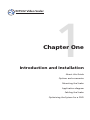
1
Chapter One
Introduction and Installation
About this Guide
Options and accessories
Mounting the Scaler
Application diagram
Cabling the Scaler
Optimizing the System for a DVD
Introduction and Installation
About this Guide
This setup guide describes how to quickly install, configure, and
operate the Extron IN1502 digital two input video scaler and
how to operate the optional IR 901 infrared remote control.
Throughout this guide the terms "IN1502", "video scaler", and
"scaler" are used interchangeably to refer to the IN1502 product.
Options and accessories
IN1502 optional equipment includes:
•
IR 901 remote control — Extron’s IR 901 (part #70-152-01)
is an infrared remote control which replicates all of the
front panel controls of the IN1502 except the Menu and
Next buttons.
•
Rack shelf mounting kit — The 1U high, half rack width
IN1502 can be rack mounted using the universal rack shelf
mounting kit RSU 129 (part #60-190-01) or the basic rack
shelf mounting kit RSB 129 (part #60-604-01).
•
Accessories — Refer to the Appendix, "Reference, Parts
and Accessories".
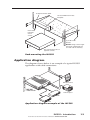
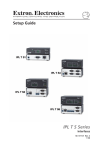
Mounting the Scaler
Tabletop/desktop placement
For tabletop or desktop placement only, install the self-adhesive
rubber feet/pads (provided) on the four corners of the bottom of
the enclosure.
Rack mounting
N For Underwriters Laboratories (UL) guidelines pertaining
to the safe installation of the IN1502 in a rack, see the
IN1502 User's Manual located on the included CD ROM
or at www.extron.com.
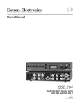
If feet were installed on the bottom of the IN1502, remove them.
Place the IN1502 on one half of the 1U (one unit high, one unit
wide) RSU 129 rack shelf (part #60-190-01). Refer to the
illustration for rack mounting the IN1502.
1-2
IN1502 • Introduction
Refer also to the IN1502 User’s Manual at www.extron.com.
HalfRackStandardShelf
1U Universal Rack Shelf
1/2 Rack Width Front False
Faceplate
Front false
faceplate
uses 2
screws.
(2) 4-40 x 3/16"
Screws
NOTE: Using screws longer
than 3/16” will damage the
unit and void the warranty.
Use 2 mounting holes on
opposite corners.
Rack mounting the IN1502
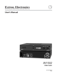
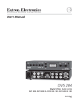
Application diagram
The diagram shown below is an example of a typical IN1502
application with cable connections.
OTE
REM
RS-232 Control
RGB
O
U
T
VID
I
N
P
U
T
S
ITE
OS
MP
EO
3
CO
2
IN1502
Video Scaler
LCD Projector
DVD
VCR
Application diagram example of the IN1502
IN1502 • Introduction
Refer also to the IN1502 User’s Manual at www.extron.com.
1-3
Introduction and Installation
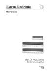
Cabling the scaler
Refer to the following diagram for connections to the IN1502.
Video input 1: Composite video
Connect a composite video signal
to this female BNC connector.
100-240V
Remote (RS-232/contact closure) 9-pin port
Provides two-way RS 232 communication and
contact closure control.
REMOTE
0.3A
I
N
P
U
T
S
COMPOSITE
S-VIDEO
1
2
50/60 Hz
AC power connector
Plug a standard IEC power cord to
a 100 to 240 VAC, 50 Hz or 60 Hz
power source. The front panel LCD
display and input selection LEDs
light during power-up.
Video input 2: S-video
Connect an S-video signal
to this 4-pin mini-DIN
female connector.
RGB
O
U
T
RGB 15-pin HD video output
Connect an RGB video display.
IN1502 rear panel connectors
Optimizing the System for a DVD Player
To obtain optimal performance when using a DVD as a
video source, Extron recommends the DVD player be set to
output an aspect ratio of 16:9 and not 4:3. Since all DVDs are
mastered as 16:9, if set up for 4:3 the player will internally
scale and compress the signal. This will defeat the automatic
3:2 pulldown detection in the IN1502.
Sizing adjustments to correct aspect ratio should be done using
the IN1502 controls.
1-4
IN1502 • Introduction
Refer also to the IN1502 User’s Manual at www.extron.com.
IN1502 Video Scaler
2
Chapter Two
Front Panel Operation
Front Panel Controls and Indicators
Menus, Configuration, and Adjustments
Picture Control
Output Configuration
Advanced Configuration
Input & System Reset
Front Panel Security Lockout (Executive Mode)
IR 901 Infrared Remote Control
Troubleshooting
Front Panel Operation
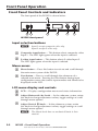
Front Panel Controls and Indicators
The front panel of the IN1502 is shown below.
3
1
2
MENU
ADJUST
IR
IN 1502
NEXT
VIDEO SCALER
1
2
4
5
6
7
IN1502 front panel
Input selection buttons
N Input 1 accepts composite video only.
Input 2 accepts S-video only.
a
Composite input button — This button selects composite video
Input 1. The LED lights green when the input is selected.
b
S-video input button — This button selects S-video Input 2.
The LED lights green when the input is selected.
Menu access
c
Menu button — Press this button to activate and scroll through
the main menu system of the IN1502.
d
Next button — Press to scroll through the submenus of a
selected main menu. Pressing the Next button during input
configuration causes the current input number and format to be
displayed on the LCD.
LCD menu display and controls
e
f
LCD — Displays configuration menus and status information.
g
Adjust Vertical ({) knob — In the submenu system, rotate
this knob to change adjustment values, toggle settings or scroll
through menu options.
Adjust Horizontal ([) knob — In the submenu system, rotate
this knob to change adjustment values, toggle settings or scroll
through menu options.
N The Adjust knobs have no mechanical limits to their
rotation.
2-2
IN1502 • Front Panel Operation
Refer also to the IN1502 User’s Manual at www.extron.com.
Menus, Configuration, and Adjustments
Scaler configuration and adjustments are done using the front
panel controls and menus displayed on the LCD screen, or by
using the Simple Instuction Set (SIS™) commands via the RS‑232
port. This setup guide provides installation and operating
instructions using the front panel. Further details on software
control can be found in the IN1502 User's Manual located on the
included CD-ROM and at www.extron.com.
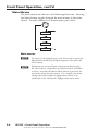
Menu overview
After the initial power up sequence, and when no adjustments
are being made, the default display appears on the LCD screen.
The screen cycles between the active input number and video
format, and the output resolution and rate, as shown in the
flowchart below.
Power
on
INPUT 1
CMPOSITE
Power up
Sequence
2 sec.
EXTRON
IN1502
2 sec.
60-726-1
FW v.1.00
2 sec.
Default Display Cycle
2 sec.
INPUT 1
CMPOSITE
2 sec.
1024 x 768
@60
or
NO
SIGNAL
Default menus
N The "No Signal" default display occurs if there is no signal
present at the currently selected input.
N From any menu or submenu, after ten seconds of inactivity
the IN1502 saves all adjustments and switches to the
default display cycle.
IN1502 • Front Panel Operation
Refer also to the IN1502 User’s Manual at www.extron.com.
2-3
Front Panel Operation, cont’d
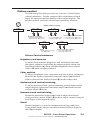
Main Menus
The main menus are shown in the following flowchart. Pressing
the Menu button toggles through the main menus in the order
shown. To enter submenus of a main menu, press Next.
DEFAULT
CYCLE
MENU
PICTURE
CONTROL
MENU
OUTPUT
CONFIG
MENU
ADVANCED
CONFIG
MENU
NEXT
EXIT
MENU
MENU
Main menus
N To return to the default cycle, wait 10 seconds or press the
Menu button until the Exit Menu appears, then press the
Next button.
N Submenus are accessed from a main menu by pressing
the Next button. Regardless of which menu or submenu
is active, any time the Main Menu button is pressed, the
next main menu becomes active. For example, the menu
changes from the Output Configuration menu or its
submenus to the Advanced Configuration main menu.
2-4
IN1502 • Front Panel Operation
Refer also to the IN1502 User’s Manual at www.extron.com.
Picture control
The following flowchart provides an overview of the Picture
control submenus. Picture controls allow adjustment of each
input for optimum picture quality of the output display. The
picture controls are active for the input currently selected.
Default
Cycle
Default values are shown.
MENU
PICTURE
CONTROL
NEXT
BRT
128
CONT
128
NEXT
Brightness and Contrast
• Brightness range: 000 to 255.
• Contrast range: 000 to 255.
NEXT
COL
128
TINT
128
NEXT
H CNTR V
128
128
NEXT
Horizontal and Vertical Centering
Color and Tint
• Color range: 000 to 255. • H centering range: 000 to 255.
• V centering range: 000 to 255.
• Tint range: 000 to 255.
DETAIL
016
NEXT
Detail
• Detail (sharpness) ranges
from 000 to 063.
H SIZE V
128
128
Horizontal and Vertical Sizing
• H size range: 000 to 255.
• V size range: 000 to 255.
Picture Control submenus
Brightness and contrast
To adjust for maximum brightness and uniformity between
the inputs without overdriving the output display, rotate the
horizontal Adjust ([) knob to adjust brightness and vertical
Adjust ({) knob to adjust contrast.
Color and tint
To adjust for proper color saturation and tint, and for uniformity
between the inputs, rotate the horizontal Adjust ([) knob to
adjust color and the vertical Adjust ({) knob to adjust tint.
Horizontal and vertical centering
To adjust horizontal and vertical centering of each input on the
output display, rotate the horizontal Adjust ([) knob and the
vertical Adjust ({) knob.
Horizontal and vertical sizing
Rotate the horizontal Adjust ([) knob to adjust horizontal
sizing and the vertical Adjust ({) knob to adjust vertical sizing of
each input on the output display.
Detail
Detail (sharpness) is used to compensate for long cable runs.
Using either knob, adjust to restore fine detail of each input in
the output display.
IN1502 • Front Panel Operation
Refer also to the IN1502 User’s Manual at www.extron.com.
2-5
Front Panel Operation, cont’d
Output Configuration
The following flowchart provides an overview of the Output
Configuration submenus and options for each setting.
Default
Cycle
MENU
PICTURE
CONTROL
MENU
OUTPUT
CONFIG
NEXT
1024 x 768 @60 Hz
RES
REFRESH
NEXT
Scaler output rates
• See the scaler output table. All
resolutions available at 50 and
60 Hz.
Default: 1024 x 768 @60 Hz
H SYNC V
NEG
POS
H FORMAT
<H>
HV
NEXT
Sync polarity
• H- / V- (default)
• H- / V+
• H+ / V• H+ / V+
NEXT
Sync output format
• H (default) – Separate
• HV – Composite
Resolution and refresh rates
Rotate the horizontal Adjust ([) knob while in this submenu
to select one of the available combinations of output resolution
rates.
Rotate the vertical Adjust ({) knob while in this submenu to
select one of the available refresh (vertical scanning) rates.
Scaler Output Resolutions @ 50/60 Hz
• 640 x 480
• 1024 x 768
• 800 x 600
• 1280 x 768
• 848 x 480
• 1360 x 765
• 852 x 480
• 1366 x 768
N Default is 1024 x 768 @ 60Hz
Sync polarity
The display or projector may require a specific combination of
horizontal (H) and vertical (V) sync signal polarities. Rotate
either adjust knob to select the appropriate sync polarity
combination.
H format
The display or projector may require separate horizontal and
vertical sync or composite (combined horizontal and vertical)
sync. Rotate either adjust knob to select "HV" for composite
sync or "H" to output horizontal and vertical sync separately.
2-6
IN1502 • Front Panel Operation
Refer also to the IN1502 User’s Manual at www.extron.com.
Default
Cycle
Advanced configuration
MENU
The following flowchart provides an overview of the Advanced
Configuration submenus.
PICTURE
CONTROL
MENU
OUTPUT
CONFIG
MENU
ADVANCED
CONFIG
T BLNK B
000
000
NEXT
BLUEMODE
<OFF> ON
NEXT
Blue and sync only
• On
• Off (default)
Top and bottom blanking
• Top blanking ranges from 000
(default) to 127
• Bottom blanking ranges from
000 (default) to 127
NEXT
2:2 PLDN
<OFF> ON
PAL film mode
• On
• Off (default)
NEXT
NEXT
AUTOSW
<OFF> ON
Autoswitch mode
• On
• Off (default)
Advanced Configuration Submenus
Top and bottom blanking
During scaling, head switching artifacts or extraneous material
such as closed captioning may cause noise at the top and/or
bottom of the video. Blanking adds black lines to mask that
noise. The inputs can have separate settings.
Rotate the Adjust ([) knob to increase top blanking.
Rotate the Adjust ({) knob to increase bottom blanking.
Blue mode
To aid in setup of color and tint, blue mode allows only sync and
blue video signals from the selected input to the display.
Use either Adjust knob to toggle "On" or "Off".
Autoswitch (Autosw) mode
If both inputs have active signals, automatically selects Input 2.
Use either Adjust knob to toggle "On" or "Off".
2:2 Pulldown detection (PAL film mode)
Optimizes PAL video originating from film. For standard PAL
video sources, such as cameras, set this feature to "Off" (default).
N 3:2 pulldown detection is always on for NTSC video
sources.
Use either Adjust knob to toggle "On" or "Off".
IN1502 • Front Panel Operation
Refer also to the IN1502 User’s Manual at www.extron.com.
2-7
Front Panel Operation, cont’d
Exit menu
From this submenu, press the Next button to return to the
default menu cycle, or press the Menu button to return to the
picture control menu.
Input Reset
To reset each input of the IN1502 scaler to its default centering
and sizing values, hold down the specific input button until the
Input # Reset message is displayed on the LCD screen.
N Autoswitch must be set to "OFF" before input reset can be
used. See "Autoswitch (Autosw) mode".
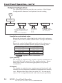
System Reset
To reset the IN1502 to default values;
1.
Remove AC power.
2.
Press and hold the input 1 button while simultaneously
plugging in the power cord.
The System Reset message is displayed on the LCD screen.
Front Panel Security Lockout (Executive Mode)
To prevent accidental changes to settings, executive mode locks
all front panel functions except the input selection buttons. With
executive mode active, all functions and adjustments can still be
made through RS-232 control or with the optional IR 901 remote
control. For details on RS-232 control, see chapter 3, "Serial
Communication", of the IN1502 User's Manual.
Enable Executive Mode
Default
Cycle
Disable Executive Mode
Default
Cycle
MENU
MENU
Press simultaneously
for 2 seconds
Press simultaneously
for 2 seconds
NEXT
NEXT
EXE MODE
ENABLED
EXE MODE
DISABLED
10 sec.
timeout
10 sec.
timeout
N The input selection buttons (Input 1 and Input 2) remain
functional during front panel lockout.
2-8
IN1502 • Front Panel Operation
Refer also to the IN1502 User’s Manual at www.extron.com.
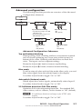
Troubleshooting
The following tips may assist troubleshooting.
1.
Some symptoms may resemble others, so look through all
examples before attempting to solve the problem.
2.
Be prepared to backtrack in case the action does not solve
the problem.
3.
Keep notes and sketches in case the troubleshooting
process gets lengthy. This also provides information if
calling technical support.
4.
Try simplifying the system by eliminating components
that may have introduced the problem or made it more
complicated.
5.
For sync-related problems: Sync problems may result
from using long cables or from improper termination.
A sync adapter, such an Extron ASTA (active sync
termination adapter, part # 26-488-01), may help solve
these problems.
6.
For LCD and DLP projectors and plasma displays:
In addition to the sync-related information above,
check the user manual that came with the projector for
troubleshooting tips and for settings and adjustments.
The table below shows some common operating problems and
solutions.
Problem
Cause
Solution
No image appears.
The input signal is
incompatible.
Attach an input device
that is compatible with
NTSC 3.58, NTSC 4.43, PAL,
or SECAM.
Freeze mode was entered
when the image was black.
Deactivate freeze mode.
The scaled output rate is too Change the scaled output to
high for the display.
a compatible resolution.
Image is frozen.
Freeze mode is on.
Deactivate freeze mode.
Alternately, remove power
from the scaler for a short
time, then reconnect power..
Image is flashing.
The output rate is incorrect
for the display.
Change the scaled output to
a compatible resolution.
Change the display
resolution to match the
scaled output.
The image is too
soft.
The detail level needs to be
changed.
Change the detail level.
IN1502 • Front Panel Operation
Refer also to the IN1502 User’s Manual at www.extron.com.
2-9
Front Panel Operation, cont’d
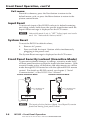
IR 901 Infrared Remote Control
The IR 901 replicates all front panel controls except the Menu
and Next buttons. If executive mode has been enabled, input
selection and adjustments can still be made using the IR 901.
The IR 901 is shown. Buttons that are shown in gray are not
functional.
Freeze an input
To freeze the input being displayed,
press the Freeze On/Off button. The
video remains frozen until a different
input is selected or the Freeze button is
pressed again.
Select an input
To select an input source, press an input
button (1 or 2).
Size and center
Use the Size and Center buttons to
adjust the sizing and centering aspects
of the displayed image.
Image adjustments
The color, tint, brightness, contrast,
and detail of a displayed image may
be adjusted by using the appropriate
Image Adjustments button.
EXTRON
2-10
IR 901
DVS/QSD REMOTE
IN1502 • Front Panel Operation
Refer also to the IN1502 User’s Manual at www.extron.com.
IN1502 Video Scaler
3
Chapter Three
Switcher Software
Remote Control port setup
Switcher Software
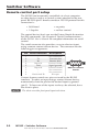
Remote control port setup
The IN1502 can be remotely controlled via a host computer
or other device (such as a control system) attached to the rear
panel RS-232 9-pin D female connector. RS-232 protocol for this
connection is:
• 9600 baud
• no parity
• 1 Stop bit
• no flow control
The control device (host) can use the Extron Simple Instruction
Set (SIS) commands. See Chapter 3 "Serial Communications",
of the IN1502 User's Manual for complete information on serial
control.
The serial connector also provides a way to select an input
using a remote contact closure device. The connector has the
following pin assignments:
Pin RS-232 function
1
2
3
4
5
6
7
8
9
–
Tx
Rx
Input #1
Gnd
Input #2
–
–
Hardwired IR
Description
No connection
Transmit data
Receive data
Contact closure
Signal ground
Contact closure
No connection
No connection
IR input
5
1
9
6
DB9 Pin Locations
Female
Contact closure control uses pins not used by the RS-232
interface. To select an input using a contact closure device,
momentarily short the pin for the desired input to ground
(pin 5). To force one of the inputs to always be selected, leave
the short in place.
N The short overrides front panel input selections.
3-2
IN1502 • Switcher Software
Refer also to the IN1502 User’s Manual at www.extron.com.
IN1502 Video Scaler
A
Appendix
Reference, Parts and
Accessories
Specifications
Part numbers and accessories
Firmware upgrade
Reference, Parts and Accessories
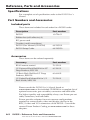
Specifications
For a complete set of specifications refer to the IN1502 User's
Manual.
Part Numbers and Accessories
Included parts
These items are included in each order for a IN1502 scaler:
Description
Part number
IN1502
60-726-01
Rubber feet (self-adhesive) (4)
IEC power cord
Tweeker (small screwdriver)
IN1502 User Manual (CD ROM)
68-1205-01
IN1502 Setup Guide
68-1205-50
Accessories
These items can be ordered separately:
Accessory
Part number
IR 901 remote control
70-152-01
1U Universal Rack Shelf Kit for 9.5"
Deep Products, RSU 129
60-190-01
1U Basic Rack Shelf for 9.5" Deep
Products, RSB 129
60-604-02
1U Under-Desk Mount Kit for 1/2
Rack Width, MBU 129
70-219-01
Please consult the IN1502 User's Manual found at
www.extron.com or the included CD ROM for a complete list of
optional accessories, pre-cut cables, connectors and bulk cable.
For highest quality and compatibility always use Extron pre-cut
cable, connectors, and bulk cable.
Extron provides adapters for most common configurations
required to connect audio, video and display devices to the
BNC, S-video and VGA connectors of the IN1502. Consult the
current Extron Product Catalog or www.extron.com for these
adapters.
A-2
IN1502 • Reference, Parts and Accessories
Refer also to the IN1502 User’s Manual at www.extron.com.
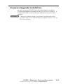
Firmware Upgrade Installation
In some cases the IN1502 firmware may require an update.
The full procedure is included in the IN1502 User's Manual. It
is recommended to return the unit to Extron for service and
updates.
C Changes to firmware must be performed by authorized service
personnel only. Some IN1502 firmware updates must be done at
the Extron factory.
IN1502 • Reference, Parts and Accessories
Refer also to the IN1502 User’s Manual at www.extron.com.
A-3
Reference, Parts and Accessories, cont'd
A-4
IN1502 • Reference, Parts and Accessories
Refer also to the IN1502 User’s Manual at www.extron.com.
Extron’s Warranty
Extron Electronics warrants this product against defects in materials and workmanship
for a period of three years from the date of purchase. In the event of malfunction during
the warranty period attributable directly to faulty workmanship and/or materials,
Extron Electronics will, at its option, repair or replace said products or components,
to whatever extent it shall deem necessary to restore said product to proper operating
condition, provided that it is returned within the warranty period, with proof of
purchase and description of malfunction to:
USA, Canada, South America,
and Central America:
Extron Electronics 1001 East Ball Road
Anaheim, CA 92805, USA
Europe, Africa, and the Middle
East:
Extron Electronics, Europe
Beeldschermweg 6C
3821 AH Amersfoort
The Netherlands
Asia:
Extron Electronics, Asia
135 Joo Seng Road, #04-01
PM Industrial Bldg.
Singapore 368363
Japan:
Extron Electronics, Japan
Kyodo Building,
16 Ichibancho
Chiyoda-ku, Tokyo 102-0082
Japan
This Limited Warranty does not apply if the fault has been caused by misuse, improper
handling care, electrical or mechanical abuse, abnormal operating conditions or
non‑Extron authorized modification to the product.
If it has been determined that the product is defective, please call Extron and ask for an
Applications Engineer at (714) 491-1500 (USA), 31.33.453.4040 (Europe), 65.6383.4400
(Asia), or 81.3.3511.7655 (Japan) to receive an RA# (Return Authorization number). This
will begin the repair process as quickly as possible.
Units must be returned insured, with shipping charges prepaid. If not insured, you
assume the risk of loss or damage during shipment. Returned units must include the
serial number and a description of the problem, as well as the name of the person to
contact in case there are any questions.
Extron Electronics makes no further warranties either expressed or implied with respect
to the product and its quality, performance, merchantability, or fitness for any particular
use. In no event will Extron Electronics be liable for direct, indirect, or consequential
damages resulting from any defect in this product even if Extron Electronics has been
advised of such damage.
Please note that laws vary from state to state and country to country, and that some
provisions of this warranty may not apply to you.
Extron USA - West
Headquarters
+800.633.9876
Inside USA / Canada Only
+1.714.491.1500
+1.714.491.1517 FAX
Extron USA - East
Extron EMEA
Extron Asia
Extron Japan
Extron China
Extron Middle East
+800.633.9876
+800.3987.6673
+800.7339.8766
+81.3.3511.7655
+81.3.3511.7656 FAX
+400.883.1568
+971.4.2991800
+971.4.2991880 FAX
+1.919.863.1794
+1.919.863.1797 FAX
+31.33.453.4040
+31.33.453.4050 FAX
+65.6383.4400
+65.6383.4664 FAX
Inside USA / Canada Only
Inside Europe Only
Inside Asia Only
© 2008 Extron Electronics. All rights reserved.
Inside China Only
+86.21.3760.1568
+86.21.3760.1566 FAX