1
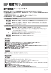
Chapter 4
Installing the Workgroup EISA HP
Adapter Hardware
This chapter explains how to install the workgroup EISA HP single
attachment and dual attachment adapters in HP Apollo workstations, connect
the cables, check the LEDs, and confirm the network connections.
Installation Overview
To install the EISA HP adapter, make sure you complete the following
procedures and have the required tools available. See Chapter 2, “Preparing
for Installation.”
•
Turn off the power to the workstation after following normal software
shutdown procedures.
•
•
•
•
•
Remove the system cover.
Install the EISA HP adapter.
Replace the system cover.
Connect the CDDI or FDDI cables.
Apply power to start up the workstation.
Installing the EISA HP Adapter
This section provides general instructions for installing the EISA HP single
attachment or dual attachment adapters in an HP Apollo workstation.
Included are brief instructions to follow for Model 720, 730, and 750
workstations. For specific instructions for these and other models, refer to HP
Apollo Model 7xx Owner’s Guide for HP-UX Users, which is provided with
your workstation.
Caution Make sure that your workstation is powered down before
you begin this procedure.
Installing the Workgroup EISA HP Adapter Hardware
4-1
Inserting the EISA HP Adapter
Once you have removed the workstation’s top cover and located an available
bus-master EISA slot, you can insert the EISA HP adapter.
Models 720 and 730: remove the EISA interface assembly at the rear
of the workstation. Remove the five screws, and pull the handle to
remove the assembly. See Figure 4-1.
EISA slot 1
Figure 4-1 Model 720/730 EISA Interface
Workgroup CDDI/FDDI EISA HP Adapter User Guide
4-2
H2362
Step 1
Step 2
Model 750: unscrew the knob to remove the top and side covers.
Push down on the top of the radio frequency interference (RFI)
shield to release the top tabs. Pull the shield up and away from the
workstation to release the bottom tabs. See Figure 4-2.
H2361
Top tabs
RFI shield
Side cover
Bottom tabs
RFI shield
Figure 4-2 Model 750 Cover and RFI Shield Removal
Step 3
Remove the slot cover(s) to expose the desired EISA slot(s). Use the
slot cover screws to secure the adapter.
Installing the Workgroup EISA HP Adapter Hardware
4-3
Step 4
Without touching any electrical components, slide the adapter into
the slot. Press firmly into place. See Figure 4-3.
Retaining
screw
H2360
Retaining
screw
Model 720/730
Model 750
Figure 4-3 Inserting the EISA Adapter in the EISA Slot
Step 5
Secure the adapter with the screw that held down the slot cover.
Step 6
Reassemble the system.
Connecting the Cables
Connect the EISA HP adapter to the network as follows:
Step 1
Connect one end of the network cable to the EISA HP adapter port.
Step 2
Connect the other end of the cable to a CDDI/FDDI network outlet.
Step 3
Verify that your adapter is connected to the concentrator and that the
concentrator is plugged in and connected to the network.
Workgroup CDDI/FDDI EISA HP Adapter User Guide
4-4
Note You must install the EISA HP adapter driver and utilities before your
workstation is logically connected to the network.
Connecting to a Bypass Switch (FDDI only)
You can connect an optional bypass switch to maintain connectivity to the
FDDI ring. If a station enters a fault condition or is powered down or
rebooted, the ring will not wrap if a bypass switch is present on the faulty
station. Figure 4-4 shows how the bypass switch connects to the network and
dual attachment adapter.
Bypass switch
B
B
A
FDDI
A
H2383
EISA HP
dual attachment
adapter
Figure 4-4 Connecting a Bypass Switch
Checking the Adapter LEDs
To verify proper operation of the EISA HP adapter, apply power to the
workstation and check the LEDs on the adapter faceplate.
Status LED
The status LED shows the adapter’s status. If this LED is on, the adapter has
passed its internal diagnostics self-test. This LED must be on for the adapter
to function properly.
If the LED is not on, the EISA adapter has failed a critical diagnostic self-test.
Run fddistat to determine the cause of the failure (see Appendix C, “Using the
FDDI Status Utility”), and call the Cisco Technical Assistance Center.
Installing the Workgroup EISA HP Adapter Hardware
4-5
Ringop LED
Verify connection to the ring by observing the ringop LED.
In a single attachment configuration, the ringop LED monitors ring operation.
If this LED is on, the adapter is connected to the CDDI/FDDI ring.
In a dual attachment configuration, the ringop LEDs on the dual attachment
adapter provide a visual indication of the state of your network. The ringop
LED information in Table 4-1 will help you determine if your network is
functioning properly.
Table 4-1
Ringop LED Indicators
Ringop B Off
Ringop B Green
Ringop B Orange
Ringop A Off
Ring is not
operational.
Station is in
wrap_B. Ring is an
operational SAS1.
Ring A is not a
connected DAS2.
Ring is not
operational. The
station connected to
PHY B is attempting
to connect, but has
failed.
Ringop A Green
Station is in
wrap_A. Ring B is
not connected.
Station is in thru
mode. Ring is
operational.
Station is in
wrap_A. The
station connected to
PHY B is attempting
to connect, but has
failed.
Ringop A
Orange
Ring is not
operational. The
station connected
to PHY A is
attempting to
connect, but has
failed.
Station is in
wrap_B. The station
connected to PHY
A is attempting to
connect, but has
failed. This is
normal if the station
is dual homed.
Ring is not
operational. The
stations connected
to PHY A and
PHY B are
attempting to
connect, but have
failed.
1. SAS = single attachment station.
2. DAS = dual attachment station.
Workgroup CDDI/FDDI EISA HP Adapter User Guide
4-6
Verifying the Installation
You can verify the installation of your EISA HP adapter by viewing the startup information. The following text shows an example of the information you
can expect to see.
Note Information shown as boldface screen font in the following example
confirms the EISA HP adapter driver installation.
Mar 23 16:50
Beginning I/O System Configuration.
Block TLB entry #5 from 0xf9000000 to 0xf9ffffff allocated.
HPA1924A Bit-Mapped Display (revision 8.02/10) in SGC slot 1
SGC at select code 0x10
NCR C700 Core SCSI Interface at select code 0x20 : function number 1
Built in LAN controller found at select code 0x20 : function number 2
HIL interface at select code 0x20 : function number 3
Built-In RS-232C Serial Interface at select code 0x20 : function number 4
Built-In RS-232C Serial Interface at select code 0x20 : function number 5
parallel port at select code 0x20 : function number 6
EISA System Board Iomap Size: 1024
1 Slot EISA Expander Initialized: HWPC000
EISA SLOT 1: CRS3204 at select code 0x41
CONSOLE is on the ITE
I/O System Configuration complete.
Configure called
Swap device table: (start & size given in 512-byte units)
entry 0 - auto-configured on root device; SCSI: sense key, lun 0, target
6, bus 0: Unit Attention
SCSI: sense code, lun 0, target 6, bus 0: Power On or Reset or Bus Device
Reset
SCSI: Status bytes, lun 0, target 6, bus 0:
70 0 6 0 0 0 0 e 0 0 0 0 29 0 0 0 0 0 0 0 0 0
SCSI: lun 0, target 6, bus 0, ASC 29, ASCQ 0, sense key 6, ASL e,
sense key specific bytes: 0 0 0
start = 639360, size = 184270
Core image of 4096 pages will be saved at block 395431 on device 0x7201600
@(#)B2352A HP-UX (A.08.07) #1: Wed Nov 06 09:34:43 MST 1991
physical page size = 4Kb
real mem = 16777216
lockable mem = 9408512
avail mem = 11128832
using 204 buffers containing 1675264 bytes of memory
lan1 driver rev: 2.1 hw rev: 3.1 fw rev: 3.3
lan1 diagnostics passed. 0x0
lan1 address 00:40:0b:40:18:89 (00:02:d0:02:18:91)
lan1 ring up
Installing the Workgroup EISA HP Adapter Hardware
4-7
Confirming IP, Netmask, and Broadcast Addresses
After installing the adapter driver and hardware, use the ifconfig, ping, and
fddistat commands to display EISA HP adapter driver confirmation
information. Following are examples of the ifconfig and ping commands. See
Appendix C, “Using the FDDI Status Utility,” for examples of the fddistat
command.
ifconfig Command Example
Use the ifconfig command as in the following example to display the current
FDDI configuration:
root@console: => ifconfig lan1
lan1: flags=63<UP,BROADCAST,NOTRAILERS,RUNNING>
inet 198.133.219.59 netmask ffffff00 broadcast 198.133.219.255
root@console: =>
The IP address 198.133.219.59 is the address you assigned in the installation
script.
Note The IP address and the netmask address are usually assigned by your
network administrator.
Confirming Connections to Network Devices
You can use the ping command to determine if your adapter is connected to
the network or other devices on the network. Typically, you will want to ping
the following devices:
•
The EISA HP adapter, to confirm that the adapter driver is properly
installed
•
Another workstation on the ring, to confirm that the adapter is properly
connected to the network
Enter the ping command as in the following example:
root@console: screens => ping hostname
64 bytes from 198.133.219.99: icmp_seq=0. time=1. ms
64 bytes from 198.133.219.99: icmp_seq=1. time=0. ms
Workgroup CDDI/FDDI EISA HP Adapter User Guide
4-8
64 bytes from 198.133.219.99: icmp_seq=2. time=0. ms
64 bytes from 198.133.219.99: icmp_seq=3. time=0. ms
64 bytes from 198.133.219.99: icmp_seq=4. time=0. ms
----sgimonitor-fddi PING Statistics---5 packets transmitted, 5 packets received, 0% packet loss round-trip (ms)
min/avg/max = 0/0/1
root@console: =>
You can further verify the installation by using the nettl and netstat utilities
(see the appropriate man pages).
ttcp—Performance Measurement
The performance of the EISA HP adapter can be monitored using the
following test setup (wich is similar to Figure 4-5) and the ttcp utility.
A
US
OP
B
P
P
AT
NG
RA
TH
RA
ST
RI
W
W
RU
H2357
Note Disable the Ethernet interfaces of the workstations prior to running the
ttcp utility.
1/A
11
12
13
14
15
16
17
3
4
5
6
7
8
9
2/B
TRAFFIC %
1 25
50 75
100
Elvis-fddi (receiver)
Jackson-fddi (transmitter)
Figure 4-5 ttcp Hardware Test Configuration
In the following examples, refer to Figure 4-5.
Installing the Workgroup EISA HP Adapter Hardware
4-9
The TCP measurements format of the ttcp command is as follows:
From the receiver:
Elvis-fddi: ttcp -r -v -R51000
From the transmitter:
Jackson-fddi: ttcp -t -v -S51000 Elvis-fddi
The UDP measurements format of the ttcp command is as follows:
From the receiver:
Elvis-fddi: ttcp -r -u -v -R51000
From the transmitter:
Jackson-fddi: ttcp -t -u -v -S51000 Elvis-fddi
Note To ensure optimal performance, precede the ttcp command with the
nice command.
EXAMPLE
nice -20 ttcp -r -v -R51000
Confirming the Operation of the SNMP Agent
You can confirm an SNMP agent from a network management station. Refer
to your network management station manual for information on how to
confirm that the SNMP agent is functioning properly.
Workgroup CDDI/FDDI EISA HP Adapter User Guide
4-10