1
SMT118
User Manual
Version 1.0
Page 2 of 20
SMT118v2 User Manual
Revision History
Date
Comments
Engineer
Version
22/7/03
First release
GP
1.0
Version 1.0
Page 3 of 20
SMT118v2 User Manual
Table of Contents
Revision History.......................................................................................................... 2
Table of Contents ....................................................................................................... 3
Block Diagram ............................................................................................................ 4
Power Supply ............................................................................................................. 5
TIM sites ..................................................................................................................... 6
JTAG....................................................................................................................... 6
Global Bus .............................................................................................................. 6
CPU ........................................................................................................................ 6
I/O ........................................................................................................................... 6
Comm-ports ............................................................................................................ 7
Reset .......................................................................................................................... 7
Flash........................................................................................................................... 8
TTL ............................................................................................................................. 8
QUART ....................................................................................................................... 9
Interrupts .................................................................................................................. 10
Memory Map............................................................................................................. 12
Board Size ................................................................................................................ 12
Connector Pin-Outs .................................................................................................. 13
CONN2 - DAC....................................................................................................... 13
CONN8 - RESET .................................................................................................. 13
CONN3 – TTL I/O ................................................................................................. 14
CONN4-7 – RS232 ............................................................................................... 14
CONN9 - JTAG ..................................................................................................... 15
Connector Position ................................................................................................... 16
How To ..................................................................................................................... 17
Write to flash ......................................................................................................... 17
Read / Write to RS232 .......................................................................................... 18
Safety ....................................................................................................................... 20
EMC ......................................................................................................................... 20
Physical Properties................................................................................................... 20
Version 1.0
Page 4 of 20
SMT118v2 User Manual
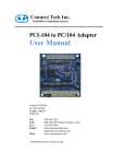
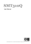
Block Diagram
From the block diagram it can be seen that this is a three slot TIM carrier with a CPU
site, two I/O sites and various types of I/O.
Each of the sections will be described in detail below.
Version 1.0
Page 5 of 20
SMT118v2 User Manual
Power Supply
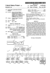
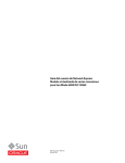
Power is supplied to the SMT118 via the 4 pin connector HDR9 (referring to
connector position section, HDR9 is located at the top right of the drawing). A
minimum current of 200mA is required by the circuitry of the SMT118. The maximum
current will be dependant on other TIMs mounted on the SMT118.
The on-board supplies are generated by custom designed industry standard pincompatible 2” x 1” DC-DC converters. The 12V module is based around the Micrel
2186 device and includes an input voltage regulator to allow a maximum of an 18V
input. The 5 and 3.3V supplies are based around the Micrel 2182 device and these
allow an input range from Vout+1.5 to 30V. The individual supplies are rated as
follows:
Voltage rail
Minimum input
Max current delivery
(Volts)
(Volts)
(Amps)
3.3
4.5
5
5.0
6.5
5
12.0
7.0
1
These values imply a minimum board supply of 7.0V. The maximum input is 18.0V.
Note that a –12V supply is not provided as standard, but an option is available to use
a dual output 12 or 15 volt DC-DC converter which will be able to supply both positive
and negative supplies to the TIM sites. When this option is installed the board supply
voltage must be greater than 10V.
Individual LEDs are illuminated when each of the DC-DC converters becomes active.
Version 1.0
Page 6 of 20
SMT118v2 User Manual
TIM sites
The SMT118 has three TIM sites. Only the primary or CPU site can be considered to
be 100% TIM standard compliant. The two I/O sites are compliant with the exception
of the optional global bus connector.
JTAG
The JTAG chain includes all three TIM sites with the proviso that there must always
be a CPU module in SITE 1.
A standard 14-pin XDS510 compatible header (CONN9) is provided to allow
debugging.
In addition to the TI standard 14-pin JTAG header, there is a 20 way 0.050” pitch
high-density connector which allows direct JTAG connection to the SMT310 series of
PCI TIM motherboards with embedded test bus controller.
Global Bus
The global bus connectors are essentially all wired in a common bus. This includes
the control signals, address and data buses. With this connectivity on the control
signals, it is evident that only the CPU site is able to generate global bus ‘master’
cycles. The two I/O sites are termed ‘slaves’, and they can contain memory mapped
resources which respond to the CPU global bus cycles.
It is not possible to insert a CPU TIM into the I/O sites unless the CPU TIM does not
have the optional global bus connector or, that the SMT118 has been specifically
modified at build time to remove these global bus connectors from the I/O sites.
CPU
The CPU TIM site connects the global bus address, data and control signals directly
to the other I/O sites’ global bus connectors.
These signals are also connected to an FPGA on the carrier board which is used to
provide the main features of this board.
Interrupts are provided via the FPGA onto the TIM IIOF and NMI signals. These
signals are inputs only to the CPU site.
I/O
The I/O sites receive the global bus address bus and control signals. They cannot
initiate a global bus cycle independently.
The four interrupt sources from each of these modules are routed to the FPGA (a
total of 8 separate interrupts).
Each I/O site has separate connectors to allow serial communication between one
another, and also to allow communication to a latching connector on the carrier
board. This provision was specifically designed for the SMT366 module and allows
the sharing of sampling clocks and outputting of DAC analog signals. There is no
Version 1.0
Page 7 of 20
SMT118v2 User Manual
additional electronic circuitry associated with these signals, so they could be used for
any general purpose requirement.
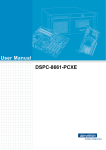
Comm-ports
Full Comm-port connectivity is provided using the following scheme:
With this method, a dual pipe exists between the modules in a 0-3 and 1-4 routing
fashion. Taking the global bus issues into consideration, three CPU TIMs could be
mounted on the SMT118 and good Comm-port communications established.
No active or passive electronic circuitry is connected to these Comm-ports but in
normal operating conditions no signal is left un-driven for any length of time.
Reset
As the SMT118 is intended for stand-alone operation, then the system reset must be
provided locally. This is implemented by a device which monitors the 5V power line
and generates a system reset to all TIM sites and on-board peripherals for
approximately ½ second after the power line is stable.
In addition to this reset mechanism there is a reset push-button switch provided, and
the shorting of the reset pin to ground (see CONN8 in connector section) will also
cause a ½ second reset.
Version 1.0
Page 8 of 20
SMT118v2 User Manual
Flash
A 16M bit flash memory is provided and can be accessed through the FPGA. This
device can be accessed in either 8-bit or 32-bit mode determined by the setting of a
control register. When accessed as a 32-bit word, 15 wait states should be inserted.
These wait states are determined by the CPU TIM. For operation with a ‘C4x TIM,
only 7 wait states need be inserted. For the setting of wait states please consult the
respective documentation for the CPU module being used.
The flash memory global address is fixed at 0xF8000000. These addresses, as are
all global addresses, are for 32-bit data. If the flash is set to word mode then all 32
bits of data are valid. If set to byte mode then only the lower 8 bits of the data word
will contain valid data.
The control register for changing the flash mode is provided at address 0xFC000000.
Setting bit 0 of this register will enable word mode.
The flash device cannot be written to when in word mode.
TTL
Twenty-four TTL I/O signals are available via the CONN3 connector. Each signal can
be set as either an input or output independently of any other signal. The direction of
these signals is controlled by the TTL direction control register at address
0xFA800000. Each of the 24 least significant bits within this register is associated
with the direction of the corresponding TTL I/O signal. Setting a bit to logic 1 will
enable that I/O as an output. After a reset, all I/O direction is set to input.
These signals are at LVTTL signal levels. They will drive a normal TTL input (V out
min of 2.4V), although the use of LVTTL inputs is suggested, they can withstand a 5V
input (an absolute maximum of 5.5V and minimum of –0.5V must be ensured).
The output state is controlled by writing to the register at address 0xFA000000, and
the input state is determined by reading from this register.
The TTL section of the FPGA can provide an interrupt source when any of the inputs
changes state. These inputs are sampled using a 60MHz clock, and so for a change
to be recognised, the new state must last longer than 15ns. This input change status
bit is cleared when the TTL data register is read (address 0xFA000000).
Version 1.0
Page 9 of 20
SMT118v2 User Manual
LEDs
Four LEDs are provided on the SMT118. These can be illuminated under application
control by writing to the register at address 0xFB000000. Bits 0 to 3 of this register
correspond to the on-board LEDs. Setting a bit to a logic 1 will illuminate the LED.
Another 4 off-board LED signals are provided. These are available on the CONN8
connector. Each of the four bits is controlled directly by the state of bits 4 to 7 of the
above register. Setting a bit to logic 1 will output a high LVTTL signal. i.e. if they are
intended to drive LEDs, then these outputs should be wired via a suitable (220Ohm
min) series resistor, to the anode of the LED. The LED’s cathode should then be
connected to ground.
QUART
The quad UART employed is an Oxford Semiconductor 16C954. It generates TXD,
RTS and DTR. It receives RXD, CTS, DSR, DCD and RI. All of these connections are
translated to true RS-232 levels and then connected to 10 pin IDC headers (CONN4
to 7) for direct connection of a standard PC pin-out 9-way D-type connector.
The UARTs within this device occupy 8 registers addresses. The base address for
the QUART is 0xF9000000, this being the base address for UART1 also.
Subsequent base addresses for the UARTs 2, 3 and 4 are 0xF9000008, 0xF9000010
and 0xF9000018 respectively.
The single QUART interrupt is connected to the FPGA and can be used to generate
a CPU interrupt.
Version 1.0
Page 10 of 20
SMT118v2 User Manual
Interrupts
Each of the four possible interrupt signal inputs to the CPU TIM (IIOF0-2 & NMI) can
be configured to generate an interrupt on any combination of the following sources:
I/O site 1 IIOF0-2, I/O site 1 NMI, I/O site 2 IIOF0-2, I/O site 2 NMI, QUART or TTL
input change.
Each of the CPU’s interrupt input signals has an independent interrupt control
register (ICR). These are accessed at addresses 0xFD000000 to 0xFD000003. The
following table shows the bit positions to set to enable the various sources:
Bit
Interrupt source
0
SITE 1 IIOF0
1
SITE 1 IIOF1
2
SITE 1 IIOF2
3
SITE 1 NMI
4
SITE 2 IIOF0
5
SITE 2 IIOF1
6
SITE 2 IIOF2
7
SITE 2 NMI
8
QUART IRQ
9
TTL input change
Setting the corresponding bit(s) will enable that interrupt source.
Version 1.0
Page 11 of 20
SMT118v2 User Manual
The state of all possible interrupt sources can be determined by reading the interrupt
status register (ISR) at address 0xFF000000.
The bit definitions are shown here:
Bit
All bits are active low.
Function
0
CPU, IIOF 0
1
CPU, IIOF 1
2
CPU, IIOF 2
3
CPU, NMI
4
I/O Site 1, IIOF 0
5
I/O Site 1, IIOF 1
6
I/O Site 1, IIOF 2
7
I/O Site 1, NMI
8
I/O Site 2, IIOF 0
9
I/O Site 2, IIOF 1
10
I/O Site 2, IIOF 2
11
I/O Site 2, NMI
12
UART RXRDY
13
UART TXRDY
14
User link 0
15
User link 1
Version 1.0
Page 12 of 20
SMT118v2 User Manual
Memory Map
Address
Resource
Comment
(hex)
F8000000
Flash
Can be accessed as 8 or 32-bit words. See CSR.
F9000000
QUART
UART1
F9000000 - F9000007
UART2
F9000008 - F900000F
UART3
F9000010 - F9000017
UART4
F9000018 - F900001F
Control
FA800000 (0=input, 1=output)
Data
FA000000
FA000000
FB000000
TTL I/O
LEDs
Data bits 0-3 set to illuminate respective LED.
Data bits 4-7 correspond to the off-board LEDs.
FC000000
CSR
Bit 0 clear to select 8-bit flash mode.
Bit 0 set to select 32-bit flash mode.
FD000000
ICR
Interrupt control register. See interrupt section.
FF000000
ISR
Interrupt status register. See interrupt section.
Board Size
The physical size of the board is 145mm x 210mm.
Using a standard IDC connector (with strain relief) inserted onto the SMT366, which
is then mounted onto the SMT118, will produce a component height of 24mm above
the top surface of the board.
Version 1.0
Page 13 of 20
SMT118v2 User Manual
Connector Pin-Outs
CONN2 - DAC
Function
Pin
Pin
Function
DAC 0 out
1
2
GND
3
4
5
6
7
8
9
10
Function
Pin
Pin
Function
RESET IN
1
2
GND
3
4
CPU BOOT
MODE
3.3V
5
6
GND
LED 4
7
8
LED 5
LED 6
9
10
LED 7
DAC 1 out
GND
CONN8 - RESET
Version 1.0
Page 14 of 20
SMT118v2 User Manual
CONN3 – TTL I/O
Function
Pin
Pin
Function
TTL I/O 0
1
2
TTL I/O 1
TTL I/O 2
3
4
TTL I/O 3
TTL I/O 4
5
6
TTL I/O 5
TTL I/O 6
7
8
TTL I/O 7
GND
9
10
TTL I/O 8
TTL I/O 9
11
12
TTL I/O 10
TTL I/O 11
13
14
TTL I/O 12
TTL I/O 13
15
16
TTL I/O 14
TTL I/O 15
17
18
TTL I/O 16
GND
19
20
TTL I/O 17
TTL I/O 18
21
22
TTL I/O 19
TTL I/O 20
23
24
TTL I/O 21
TTL I/O 22
25
26
TTL I/O 23
Function
Pin
Pin
Function
DCD
1
6
DSR
RX
2
7
RTS
TX
3
8
CTS
DTR
4
9
RI
GND
5
10
N/C
CONN4-7 – RS232
Version 1.0
Page 15 of 20
SMT118v2 User Manual
CONN9 - JTAG
Function
Pin
Pin
Function
TMS
1
2
TRST
TDI
3
4
GND
PD(+5V)
5
6
KEY
TDO
7
8
GND
TCK_RET
9
10
GND
TCK
11
12
GND
EMU0
13
14
EMU1
Version 1.0
Connector Position
Page 16 of 20
SMT118v2 User Manual
Version 1.0
Page 17 of 20
SMT118v2 User Manual
How To
This section is intended to provide code segments showing the operation of some of
the SMT118’s features. All of the code has been written for the SMT3x5 TIM, but
could easily be recompiled for another module.
In these examples, two functions, read_global and write_global are used to
access resources on the global bus. The parameters required are a 32 bit address
and optionally the data word.
Write to flash
The flash device fitted on the SMT118 has a write protect mechanism. This flash
device supports many different operations, and it is suggested that the data sheet be
read for full information. The part number is Am29LV160B.
#define flash
0xF8000000
#define flash1
0xF8000AAA
#define flash2
0xF8000555
In this function, the flash must be set to byte mode and the addr parameter is an
offset from the start of the flash.
write_flash(unsigned int addr, unsigned int data)
{
write_global(flash1, 0xAA);
write_global(flash2, 0x55);
write_global(flash1, 0xA0);
write_global(flash+addr, data);
while( (read_global(flash+addr) & 0xFF) != (data & 0xFF));
}
Version 1.0
Page 18 of 20
SMT118v2 User Manual
Read / Write to RS232
The following functions give an easy interface to the RS232 channels when
configured for simple Tx/Rx operation.
The following function is the basic UART register read routine. Supply the UART
number (0 to 3) and the register number (0 to 7).
#define uart_base
0xF9000000
int read_uart(int uart, int uart_reg)
{
int data;
data = read_global(uart_base + uart*8 + uart_reg);
return(data);
}
The following function is the basic UART register write routine. Supply the UART
number (0 to 3), the register number (0 to 7) and the required data.
write_uart(int uart, int uart_reg, int data)
{
write_global(uart_base + uart*8 + uart_reg, data);
}
The following function is the basic UART receive data routine. Supply the UART
number (0 to 3).
int rx_uart(int uart)
{
volatile int t;
// Wait for bit 0 of the UART status register to become set
// indicating that there is data in the receive FIFO.
while( ( (t=read_uart(uart, 5))
return(read_uart(uart, 0));
}
& 0x01) == 0 );
Version 1.0
Page 19 of 20
SMT118v2 User Manual
The following function is the basic UART transmit data routine. Supply the UART
number (0 to 3) and the data.
tx_uart(int uart, int data)
{
// Wait for bit 6 of the UART status register to become set
// indicating that there is an empty space in the transmit
// FIFO.
while( ((read_uart(uart, 5)) & 0x40) == 0 );
write_uart(uart, 0, data);
}
The following function shows how to initialise the UARTs for operation at 9600 baud.
The divisor is calculated as follows:
divisor = 1.8432e6 / (16 * baud rate)
The 1.8432MHz external clock is supplied by a crystal oscillator, and is such that
most standard baud rates can be produced exactly.
// Repeat process for all UART channels.
for(u=0;u!=4;u++) {
// Select the UART divisor register.
write_uart(u, 3, 0x83);
// Set divisor to 0x000C (12).
write_uart(u, 0, 0x0C); // least significant byte
write_uart(u, 1, 0x00); // most significant byte
// Select the normal UART registers.
write_uart(u, 3, 0x03);
}
Version 1.0
Page 20 of 20
SMT118v2 User Manual
Safety
This module presents no hazard to the user.
EMC
This module is designed to operate from within an enclosed host system, which is
build to provide EMC shielding. Operation within the EU EMC guidelines is not
guaranteed unless it is installed within an adequate host system.
This module is protected from damage by fast voltage transients originating from
outside the host system which may be introduced through the output cables.
Short circuiting any output to ground does not cause the host PC system to lock up
or reboot.
Physical Properties
Dimensions
211 x 145 mm
Weight
250g approx. (without TIMs).
Supply Voltage
+7 to 18V
Supply Current
Depends upon installed TIMs. See Power
Supply section.
MTBF