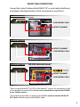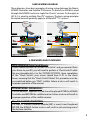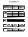
1
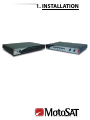
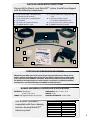
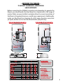
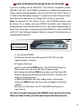
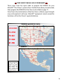
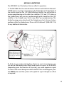
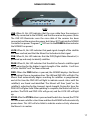
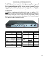
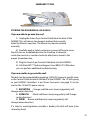
NOMAD 2 | NOMAD 3 OWNER’S GUIDE 901-NOMAD-IM Rev. 08.16.08 TABLE OF CONTENTS 1. INSTALLATION Parts Included With Your System NOMAD Specifications Systems Compatible With the NOMAD Before You Begin 3 3 3 4 NOMAD Cable Connections Mount Cable Connections Control Cable Pinout Legend Wiring Examples A Few Words About Receivers 5 6 7 8 8 2. SETUP Initial Programming NOMAD Programming Options How To Program Your MSC60 Or HD-SC2 For Zones Star Choice© Zone Mapping Limitations of Systems - MD1000.2 10 11 12 13 14 3. OPERATIONS NOMAD Front Panel -Buttons -LEDS Operating The NOMAD 16 16 17 18 4. TROUBLESHOOTING Error Codes And Troubleshooting Emergency Stow 20 21 5. UPGRADES Software Upgrade Options -Software Module / Update Module -Upgrade Via MotoSAT.com Upgrading The NOMAD Via Computer 23 23 23 24 1 1. INSTALLATION PARTS INCLUDED WITH YOUR SYSTEM Along with the Mount, your MotoSAT™ system should have shipped with the following components: 1. - (1) 30’ co-axial cable, 1-ended (female) 2. - (1) Female coaxial connector 3. - (1) 20” coaxial cable, 2-ended (female) 4. - (1) Clamshell 5. - (2) Scotch-Lok© Quick Connectors* 6. - (1) NOMAD Owner’s Guide 7. - (1) 12VDC 4AMP Power Supply with Wall Cord 8. - (1) 30’ Control Cable, 1-ended (9-conductor female Twist-Lock) 9. - (1) 9-conductor color-coded connector 10. - (1) NOMAD Universal Controller 8. 1. 10. 2. 9. 3. 4. 5*. *Only required or included with the MotoSAT™ HD Series. 7. 6. CONTROLLER VERSION SPECIFICATIONS Effective August 2008, open-faced systems began shipping with Nomad 3 Universal Controllers. However, the information contained in this Owner’s Guide applies to both the Nomad 3 and to the older NOMAD 2 Controllers. Both Nomad models are shown throughout this Guide for illustrative purposes, and all controls, connections, installation procedures and operations are identical between the NOMAD 2 and the Nomad 3. NOMAD UNIVERSAL CONTROLLER SPECIFICATIONS INTERFACE: Three-Button Power / Find / Stow TUNER: DVB [Digital Video Broadcast] Tuner Your NOMAD Controller is compatible with these skewing and non-skewing MotoSAT™ antenna systems. DIMENSIONS: 10” L x 7” W x 1.25” H WEIGHT: 2.5 lbs. CONTROLLER VOLTAGE: 12VDC 4 AMP SKEWABLE MD500 MD1000.2 MSC-60 NON-SKEWABLE EXECUTIVE 18” / 24” MHDTV HD-SL5 HD-DP3 HD-SC2 3 -- BEFORE YOU BEGIN -TV MOUNT CLEARANCES, ORIENTATION AND FOOTPRINTS Before connecting the NOMAD Controller and attempting to operate the Mount, you should verify that the Mount has clearance for a full range of motion. Make sure your installer’s work plan allows for correct orientation of the Mount, all required clearances, and all space requirements. Additionally, make sure the Mount has clearance for a full range of motion every time you park, and be sure to stow the Mount before you pull away. FOR OPEN-FACED MOUNTS: REAR OF COACH FOR DOME-STYLE MOUNTS: REAR OF COACH Output Toward Rear Dish Faces Toward Rear Clamshell Opening Toward Rear Clamshell Opening Toward Rear FRONT OF COACH FRONT OF COACH SIDE VIEW OF STOWED MOUNT SIDE VIEW OF DOME OPEN-FACED MOUNTS DOME-STYLE MOUNTS HARDWARE: - Stainless Steel or Aluminum ONLY! SEALANT: - Use ONLY approved water sealant. REMEMBER: Water Runs Downhill and Goes Into Every Hole! 4 NOMAD CABLE CONNECTIONS Power Control Cable Serial Port Out to TV In From Receiver Dish Plug in all necessary cable connections to the back of the NOMAD. (Note: Plugging the receiver and NOMAD into an independent power strip is recommended.) NOMAD Rear-Panel Connections Power: Connects the 12 VDC 4 AMP power supply to the NOMAD. (Note: Only use the power supply provided by MotoSAT™.) Control Cable: Connects the Mount to the NOMAD by way of a 9-conductor Data Cable. The cable and connector are colorcoded to insure proper configuration. (See Figure at Right). Serial Port: Used to provide software upgrades. Out to TV Receiver: Coaxial connection from the NOMAD to the satellite/LNB input on the satellite receiver. In From Dish: Coaxial connection from the Mount to the NOMAD. P1 +12V P2 GND P3 NOT USED Power Connector: Connects the 12 VDC 4 AMP power supply to the NOMAD. (Note: Only use the power supply provided by MotoSAT™). Control Cable: Connects the NOMAD to the Mount via a 9 conductor cable. The cable is color-coded to insure proper configuration. (See Figure Above). 5 MOUNT CABLE CONNECTIONS Connect the Control Cable and the NOMAD “IN” co-axial cable to the Mount according to the diagram below which corresponds to your Mount. TWO OUTPUT CONNECTOR: Executive, MD500, MHDTV, MD1000.2, MSC60 9-PIN CONTROL CABLE OUTPUT TO NOMAD† FOUR OUTPUT CONNECTOR: HD-SL5, HD-SC2 OUTPUT TO NOMAD† 9-PIN CONTROL CABLE FOUR OUTPUT CONNECTOR: HD-DP3 DISH NETWORK© DO NOT USE! *see below OUTPUT TO NOMAD† 9-PIN CONTROL CABLE When using the MotoSAT™ HD-DP3 in Dish Network© systems, this connection is used as an input from an external dish. Do not use this connection to input to the NOMAD, or to a satellite receiver. * Any output can be used as an output to the NOMAD, except as noted with the HD DP-3 above. Default output to the NOMAD is Red. † 6 CONTROL CABLE PINOUT LEGEND The Control Cable (9 conductor color-coded, 22AWG stranded) connects to the Mount with a twist-lock connector, and is configured in the following manner: Color Code Pin # Black Brown* Red* Orange Yellow Green Blue White Purple** 1 2 3 4 5 6 7 8 9 Mount Destination Motor, Azimuth Positive Motor, Azimuth/Skew Negative Motor, Elevation/Skew Positive Motor, Elevation Negative Sensor Count, Azimuth Sensor Count Ground, Azimuth/Elevation Sensor Count, Elevation LED Power Sensor Count, Skew Counts Per Degree HD Series / Executive 5.700 / 3.408 8.530 / 5.034 7.160 / 8.500 * Brown and Red are used to Skew the Dish. These wires control the Skew motors when directed by the NOMAD Controller. They are used to control the skewable systems (MD500 / MD1000.2 / MHDTV / MSC60 / HD Series.) Applying 12 volt power directly to these wires will skew the dish. ** Purple is for use on skewable systems to return counts, but it does not affect the operation of a non-skewable dish whether it is connected or not connected. Additionally, the Mount is coil-wrapped inside with the following cables and wire: 2-4 ea -RG179 coax cables terminated at the LNB provide routing between LNB and outputs. HD Series Mounts come standard with 4, all other Mounts come with standard 2 or optional 4. 1 ea -9 conductor cable, color-coded, 22AWG stranded. This cable receives Control signals from the NOMAD Controller at the twist-lock connection on the Mount, and distributes those Control signals throughout the Mount as described above. 1 ea -Green and White 22AWG stranded wires carry the positive (white voltage) and negative (green ground) to the LED which illuminate the dish face. 7 SAMPLE WIRING DIAGRAM These diagrams show basic examples of wiring setups between the Mount, NOMAD Controller, and Satellite TV Receiver. On the left, an MSC60 is wired through the NOMAD and into a single Star Choice© receiver. On the right, an HD SL-5 is wired to multiple DirecTV© receivers. The basic wiring principles illustrated here will generally apply to all MotoSAT™ TV systems. EXAMPLE - SINGLE RECEIVER EXAMPLE - MULTIPLE RECEIVERS - MOUNT - MOUNT CONTROL CABLE COAXIAL CABLE IN FROM MOUNT PWR IN FROM MOUNT COAXIAL CABLE IN FROM MOUNT PWR 12VCD 4AMP - NOMAD CONTROL CABLE IN FROM MOUNT 12VCD 4AMP OUTPUT TO SATELLITE TV RECEIVER’S INPUT - SATELLITE TV RECEIVER - NOMAD OUTPUT TO SATELLITE TV RECEIVER’S INPUT - SATELLITE TV RECEIVERS A FEW WORDS ABOUT RECEIVERS NON-SKEWABLE Open Faced Mounts: If your satellite receiver is a Dish 500© or Dish Pro© and you remove it from your home to your RV, you will need to perform a “Check Switch” while the non-skewable dish is in the STOWED POSITION. Upon completion of the “Check Switch”, your screen should have 8 X’s in the check boxes, meaning that the “Check Switch” failed. This procedure must be accomplished before you “FIND” satellite. Failure to do so will result in improper operation of the receiver. DISH NETWORK© SEPARATORS: If a Dish Network© Separator is used, it must be placed AFTER the NOMAD Controller and BEFORE the satellite receiver. Failure to do so will result in improper operation of the satellite receiver. DirecTV© B-BAND CONVERTERS: If a DirecTV© B-Band Converter Module (BBC) is used, it must be placed BEFORE the NOMAD. Failure to do so will result in not receiving one of the Ka Band satellites. 8 2. SETUP INITIAL PROGRAMMING POWER BUTTON LEDs FIND BUTTON STOW BUTTON TO PROGRAM: 1. Put The NOMAD Into Program Mode. Step 1: Make sure your NOMAD is turned Off. The green “ ” LED next to the POWER button will be dark. Step 2: Locate the FIND, STOW and POWER buttons on the NOMAD. Step 3: Press and hold down the FIND and STOW buttons at the same time. Step 4: While continuing to hold down FIND and STOW, Press the POWER button once and release. Step 5: Continue holding down the FIND and STOW buttons until all LEDs blink once (approx. 3-4 seconds), then release. 2. Program The NOMAD. • Refer to the Programming Options Chart on page 11. Determine which Program Option best matches your MotoSAT™ system and your subscriber service. Contact your Service Provider for specific information about your service. • Use the FIND or STOW button to navigate through the different settings on the front LED panel of the NOMAD. • When the LED configuration on the NOMAD matches the Programming Option you selected, press the POWER button to turn off the NOMAD. This will save your settings. • Turn on the NOMAD by pressing the POWER button. Wait 5 seconds for the NOMAD to perform startup sequences. 3. Test Dish. Step 1: Turn on the NOMAD by pressing the POWER button. Wait 5 seconds for the NOMAD to perform startup sequences. Step 2: Press and release the FIND and STOW buttons at the same time. Step 3: The STOW LED light will blink. This indicates that the dish is moving. Step 4: The STOW LED light will stop blinking and go solid. This indicates that the Test Dish completed successfully. Any other LED activity indicates an Error Code (see page 20). 4. Locate Your Programmed Satellites. • Press the FIND button. This will locate your satellite(s) based upon the configuration settings that have been programmed. 10 NOMAD PROGRAMMING OPTIONS By Service Provider For software version V25 or higher MODEL NUMBER Skew Executive (18"/24") Executive (18"/24") MHDTV HD SL-5 No No Yes Yes MODEL NUMBER Skew Executive (18"/24") Executive (18"/24") Executive (18"/24") Executive (18"/24") MD500 MD1000.2 HD DP-3 No No No No Yes Yes Yes MODEL NUMBER Skew Executive (18"/24") MD500 No Yes MODEL NUMBER Skew MSC60 HD SC-2 SHOW MODES MODEL NUMBER SKEWABLE NON-SKEWABLE Yes Yes Skew Yes No Orbital Position 1010 Only 1010 / 1190 1010 / 1100/1190 990/1010/1030/1100/1190 Orbital Position 1100/1190 61.50/1010 / 1190 1100/1190/1290 1100/1190 /1480 1100/1190 1100/1190/1290 1100/1190/1290 Orbital Position 820 / 910 820 / 910 Orbital Position 107.30 / 111.10 107.30 / 111.10 Orbital Position SHOW MODE SHOW MODE Multi Sat NOMAD LEDs No FIND No PEAK / FIND Yes FIND / STOW Yes FIND / STOW Multi Sat No No Yes Yes Yes Yes Yes Multi Sat NOMAD LEDs NO LIGHTS DVB / PEAK / FIND LOCK / FIND LOCK STOW LOCK / STOW LOCK / STOW NOMAD LEDs No PEAK Yes PEAK / STOW Multi Sat NOMAD LEDs Yes PEAK / FIND / STOW Yes PEAK / FIND / STOW Multi Sat NOMAD LEDs N/A DVB / FIND / STOW N/A DVB / PEAK 11 HOW TO PROGRAM YOUR MSC60 OR HD-SC2 FOR ZONES If you are installing one of MotoSAT’s™ Star Choice©-compatible systems (MSC60 or HD-SC2), your NOMAD will require an additional programming step to specify what geographic area (or Zone) the Star Choice© Mount is in. Refer to the Zone Maps on page 13 to determine which Zone you are in, then follow the steps below to configure the system for your Zone. Note: To program for Star Choice© Zones, your NOMAD firmware must be Version 33 or higher and your NOMAD Controller must already be programmed to control an MSC60 or HD SC-2. See “Initial Programming” on page 10 for information on programming the NOMAD to control an MSC60 or HD SC-2. See “Software Upgrade Options” on page 23 for information on upgrading your firmware. ZONE Selection LEDs FIND Programming your Star Choice© system for Zones is a very simple matter of holding down the FIND button and watching the LEDs. 1. Turn On the NOMAD. 2. Wait until the LEDs have flashed and STOW LED is lit solid (approximately 5 seconds.) 3. Program the Zone: a.) Press and hold the FIND button. The STOW LED will go out. When it goes out, you are in the Zone Program mode. b.) Continue to hold the FIND button down until the Zone LEDs begin to illuminate (starting with the STOW LED.) The LEDs will begin to change positions. c.) When the desired Zone LED configuration is illuminated, release the FIND button and the system will begin its search for satellites. d.) If you miss the Zone, turn OFF the NOMAD and return to step 1 above. You will not need to reprogram the NOMAD until you leave the Zone. When you leave a Zone, you will need to repeat the above process. 12 STAR CHOICE© MSC60 / HD-SC2 ZONE MAPS These maps show the input codes to program the NOMAD for your MotoSAT™ Star Choice© system’s Zone. Find the Zone where you are located, then program the NOMAD for that Zone as described on page 12. Note: Due to the size limitations of the Star Choice© reflector, signal strength may not be optimal in all zones. MotoSAT™ equipment cannot exceed the limitations of the Star Choice© signal distribution. CANADA and UNITED STATES LED LEGEND MEXICO Note: A Mexico location may require a larger dish to acquire the proper signal strength for your system. The Zones shown are not a guarantee of satellite reception. 13 MD1000.2 LIMITATIONS The MD1000.2 has 2 limitations that can affect its operation: 1. The MD1000.2 has the same limitations that exist with the Dish Network© D1000.2 home coverage. Coverage may be limited due to the footprint of the satellite signal on the 1290 High Definition Satellite. You will be able to receive programming on the other two satellites (1100 and 1190) when in the shaded areas, but you may see decreased signal strength on the 1290 satellite in the shaded areas which may affect your programming. This limited coverage may extend past the shaded areas, but is known to be a problem within the shaded areas. Please call Dish Network© (888-248-7116) for any additional information. The MotoSAT™ MD1000.2. When traveling in the shaded areas, you may see decreased signal strength on Dish Network© HD satellite 1290 that may affect your programming. 2. Dish size can make wind loading a factor. In most circumstances, you will not be affected by wind. When winds reach an excess of 30-40 MPH (depending upon the direction of the wind), you could experience signal loss due to the mount being moved off-satellite. If this should happen, press the FIND button and the system will re-peak for signal strength or re-find as required. 14 3. OPERATIONS NOMAD FRONT PANEL Your NOMAD features simple, push-button control of the Mount, along with LED visual indicators that allow you to to see the Mount’s status at a glance. Here is a brief overview of the NOMAD Front Panel. POWER BUTTON FIND BUTTON STOW BUTTON BUTTONS POWER: Provides power to the NOMAD Controller. FIND: Pressing the FIND button causes the Mount to automatically begin searching for your system’s primary satellite. This search continues until the Mount has locked onto the satellite and peaked for highest signal strength. Pressing the FIND button after you have locked onto a satellite will control one of two functions, depending on your system type: - Non-Skewable, Single-LNB Mount: Pressing the FIND button while on satellite enables you to toggle between multiple satellites. Pressing the FIND button while locked onto a satellite will direct the system to go to the next satellite in order such as: • DIRECTV© can toggle between 1010 and 1190. • Dish Network© can toggle between satellites 1100, 1190 and 1290. • Dish Network© International East can toggle between satellites 61.50, 1100, and 1190. • Dish Network© International West can toggle between satellites 1100, 1190 and 1480. • Bell ExpressVu© can toggle between satellites 820 and 910. - Skewable, Multi-LNB Mount: Pressing the FIND Button will locate all satellites available with your LNB configuration simultaneously, and repeak the dish for higher signal quality. For Programming Options and their assigned satellites, see “NOMAD Programming Options” on page 11. STOW: Pressing this button returns the dish to its stowed or travel position. 16 NOMAD FRONT PANEL LEDs LEDS LNB: When lit, this LED indicates that the coax cable from the receiver is correctly connected to the NOMAD, and that the receiver has power. (Note: The LNB LED illuminates once the coax cable of the receiver has been connected and the receiver has power, but it does NOT indicate the NOMAD Controller has power. The green “ ” LED next to the POWER button indicates the NOMAD has power.) LOCK: When lit, this LED indicates that peak signal strength of the satellite has been reached, and that the Mount has locked onto that signal. DVB: When lit, this LED indicates that the DVB (Digital Video Broadcast) is powered up and ready to identify satellites. PEAK: When lit, this LED indicates that the dish has found a satellite signal and is adjusting for the highest signal strength of the satellite. It will turn off after satellite “Lock” has been achieved. FIND: When the FIND button is pressed, the NOMAD deploys the Mount by elevating it from a stowed position. The LNB and DVB LEDs will light. The Mount then automatically begins searching for satellites as programmed, and at this time the FIND LED will light to indicate search status until the satellite(s) are found and identified. The Mount will then “peak” on the satellite(s), adjusting for the strongest signal strength. During this time, the PEAK LED will glow solid. When peaking is complete, the Mount will lock in position. The PEAK and FIND LEDs will go out, and the LOCK LED will light up. STOW: After the STOW button is pressed and the dish has stowed, the STOW LED will remain solid for a short time and then the NOMAD will automatically power down. This LED will also blink to indicate motor activity whenever the Mount is in motion. 17 OPERATING THE NOMAD TO FIND A SATELLITE: 1. Turn on the power by pressing the POWER button. 2. Wait for approximately 5 seconds for the NOMAD to complete its power up sequence. 3. Press the FIND button and the dish will search out and lock onto the properly programmed satellite(s). NOTE: Pressing the FIND button after you have locked onto a satellite will control one of two functions, depending on your system type: - Non-Skewable Mount: Pressing the FIND button while on satellite enables you to toggle between multiple satellites. Pressing the FIND button while locked onto a satellite will direct the system to go to the next satellite in order such as: • DIRECTV© can toggle between 1010 and 1190. • Dish Network© can toggle between satellites 1100, 1190 and 1290. • Dish Network© International East can toggle between satellites 61.50, 1100, and 1190. • Dish Network© International West can toggle between satellites 1100, 1190 and 1480. • Bell ExpressVu© can toggle between satellites 820 and 910. - Skewable Mount: Pressing the FIND Button will locate all satellites available with your LNB configuration simultaneously, and re-peak the dish for higher signal quality. For Programming Options and their assigned satellites, see “NOMAD Programming Options” on page 11. TO STOW THE DISH: 1. Press the STOW button and the dish will stow, returning to the proper travel position. POWER BUTTON FIND BUTTON STOW BUTTON 18 4. TROUBLESHOOT ERROR CODES AND TROUBLESHOOTING The NOMAD Controller is capable of detecting many different types of problems that may occur during operation. The Controller will signify that it has found a problem by flashing 1 or more LEDs on its face in 1-second intervals. See the table below for information about Error Codes, which LEDs will flash when an error is detected, and some possible causes and solutions for these errors. NOTE: Before accepting any of the flashing LED codes, first perform a TEST DISH to see if the error persists. (See page 10 for information on performing a TEST DISH.) If the error continues, refer to the table below. If the problem persists and you can find no solution, then please call our Technical Support Line (800) 247-7486 for further assistance. STOW No Error if dish is moving. Only an error if dish is not moving. FIND Invalid Skew Mode Reprogram Nomad (Skewable/Non-Skewable) Controller FIND-STOW Invalid Mode Reprogram Nomad Controller Motor Time Out. No counts in Elevation. Dish blocked from moving or bad Elevation Sensor PEAK-STOW Motor Time Out. No counts in Azimuth. Dish blocked from moving or bad Azimuth Sensor PEAK-FIND Motor Time Out. No counts in Skew. Dish blocked from moving or bad Skew Sensor PEAK-FIND-STOW Limit Error in Elevation movement. Dish blocked from moving or bad Elevation Sensor DVB Limit Error in Azimuth movement. Dish blocked from moving or bad Azimuth Sensor DVB-STOW Limit Error in Skew movement. Dish blocked from moving or bad Skew Sensor DVB-PEAK Only Main satellite found. Dish line of sight blocked, CAUSE/SOLUTION try different location DVB-PEAK-STOW Main satellite not found but Secondary satellite was. Dish line of sight blocked, try different location DVB-PEAK-FIND-STOW Signal lost, NO LNB Power Check Satellite Receiver power LOCK No satellite found. Dish line of sight blocked, try different location, possible cabling problem or LNB failure LOCK-STOW Over Temperature on Satellite Receiver. Operational limit of your electronics has been exceeded, provide proper ventilation ERROR CODE LEDs PEAK FLASHING LED If Stow is flashing and mount is not moving, look for stripped gears. ERROR CAUSE/SOLUTION STOW No Error if dish is moving. Only an error if dish is not moving. If Stow is flashing and mount is not moving, look for stripped gears. FIND Invalid Skew Mode Reprogram Nomad (Skewable/Non-Skewable) Controller FIND-STOW Invalid Mode Reprogram Nomad Controller PEAK Motor Time Out. No counts in Elevation. Dish blocked from moving or bad Elevation Sensor PEAK-STOW Motor Time Out. No counts in Azimuth. Dish blocked from moving or bad Azimuth Sensor PEAK-FIND Motor Time Out. No counts in Skew. Dish blocked from moving or bad Skew Sensor PEAK-FIND-STOW Limit Error in Elevation movement. Dish blocked from moving or bad Elevation Sensor LOCK-FIND Dish did not raise high enough. Dish blocked from moving or bad Elevation Sensor DVB Limit Error in Azimuth movement. Dish blocked from moving or bad Azimuth Sensor LOCK-FIND-STOW Coax cables reversed on back of Nomad. Switch cables DVB-STOW Limit Error in Skew movement. Dish blocked from moving or bad Skew Sensor LOCK-PEAK-FIND-STOW Could not find main satellite after Skew. Run TEST DISH DVB-PEAK Only Main satellite found. Dish line of sight blocked, try different location LOCK-DVB EEPROM failure. Call Technical Support LOCK-DVB-STOW AGC Control Failure. Call Technical Support FLASHING LED ERROR 20 EMERGENCY STOW STOWING THE DISH WHEN ALL ELSE FAILS: If you are able to go onto the roof: 1. Unplug the Green 9 pin Control Cable from the back of the NOMAD. This will release the dynamic braking that normally holds the Mount in position. The Mount may now be rotated manually. 2. Carefully apply a slight, continuous amount of force to move the dish into an acceptable position for traveling. In Azimuth, rotate the mount in a counter-clockwise direction to move to the proper stowed position. 3. Plug the Green 9 pin Control Cable back into the NOMAD. 4. Call MotoSAT’s™ Technical Support Line (800) 247-7486 when you can perform additional troubleshooting. If you are unable to go onto the roof : The dish can be manipulated by applying 12 Volt DC power to specific wires in the Control Cable located in the back of the NOMAD. The 12 Volts going to your NOMAD Controller’s 3 pin Power Connector (see page 5) can be used as the 12 Volt DC power source. 1. ELEVATION - Orange and Red wires (reversing polarity will change motor direction) 2. AZIMUTH - Black and Brown (reversing polarity will change motor direction.) 3. SKEW - Brown and Red wires (reversing polarity will change motor direction.) If a chain or motor/gearbox assembly is broken, the dish will have to be stowed by hand. 21 5. UPGRADES SOFTWARE UPGRADE OPTIONS Software upgrades can be accomplished in two (2) different ways: 1. The latest software version for your System is available in module form. To take advantage of this effortless upgrade simply: a. Order part number 252-NOMAD2-PM (Software Module / Update Module). You pay only shipping. We will charge you freight one way and we will include a pre-paid UPS Return Tag for the return of the module. (Note: The Module must be returned to MotoSAT™ within 30 days, or your Credit Card will be billed the cost of a replacement module.) b. Updating the software using the Software Module / Update Module can be done in less than 5 minutes. It comes with installation instructions. All you do is plug it into the Serial Port on the back of the NOMAD (see page 5) and follow the instructions listed on the device when it arrives. Serial Port A Software Module / Update Module, or SMUM (left). This module is used to load firmware revisions into the NOMAD via the serial port on the Controller’s rear panel (see above.) 2. The latest software version for your system is available online: http://www.MotoSAT.com/downloads/tv/index.asp. To load upgrades into your NOMAD via your computer, you must purchase a MotoSAT™ 15-pin to 9-pin serial cable (part number 406-D15M-SER-D9F). Call our Technical Support Line (800) 247-7486 to order this cable if you wish to upgrade via computer. You must also have a computer that has a serial port available, or have a computer that has a USB port available and a USB-to-Serial Adapter, which can be purchased from an Electronics Store. 23 Whether you chose to upgrade the software via computer or Update Module, you will be able to take advantage of software improvements as they happen. Not all upgrades will affect you. Read the “NOMAD Revision History” next to the latest software version, to see if you would benefit by loading it. If the changes do not reflect a solution to a problem you are experiencing, do not load it. UPGRADING THE NOMAD VIA COMPUTER: Required Equipment*: 1. Computer with 9-pin Serial Port. -or Computer that has a USB port available and a USB-to-Serial Adapter. 2. MotoSAT™ 15-pin to 9-pin Serial Cable (part number 406-D15M- SER-D9F). *An automatic Software Module / Upgrade Module (MotoSAT™ Part Number: 252-NOMAD-PM) is available through MotoSAT™ if these components are not available. This module plugs into the NOMAD serial port to load software. Customer must pay shipping both ways. Module must be returned otherwise customer will be billed cost of replacement module. 1. Start a program called Hyperterminal on your computer to communicate with the Nomad. It can be found by clicking START > ALL PROGRAMS > ACCESSORIES > COMMUNICATIONS > HYPERTERMINAL. 2. Name your HyperTerminal Connection “UPGRADE”. 24 3. Choose the port you wish to use to connect to your NOMAD. Generally, COM 1 is the best choice. 4. Enter properties for COM 1: - Bits Per Second: 115200 - Data Bits: 8 - Parity: None - Stop Bits: 1 - Flow Control: Xon / Xoff Click “OK”. 5. In the HyperTerminal window, click FILE > PROPERTIES > SETTINGS. Click the ASCII SETUP button. Change the LINE DELAY setting from 0 to 100. 25 6. Turn on your NOMAD Controller and press the “ * ” key [shift+8] on the keyboard within 3 seconds after powering the controller on. The following screen will appear: - If nothing appears, you have chosen the wrong com port. Refer to Step 1 on page 24 and reconfigure. - If you see ‘gain adjusted’ you have taken too long to press the “ * ” key. Retry the Controller power-up cycle again. 7. At the prompt, type fbulk and press the “ENTER” key. prompt, type fload and At the next press the “ENTER” key. • You can now send software updates to the NOMAD. In the HyperTerminal window, click “TRANSFER”, then click “SEND TEXT FILE”. • Browse for the NOMAD upgrade file you downloaded. Usually it can be found on your Desktop, or in ‘My Documents’. 8. The file will then load, as indicated by stars across the screen, as shown here: • When the software has been loaded, you prompt. will again receive the • Type default at this prompt, then press the “ENTER” key. Your NOMAD has now been upgraded! Now, run a Test Dish in order to ensure proper functionality. (See page 10 for steps on running a Test Dish.) 26 NOMAD™ CONTROLLER INFORMATION Date Of Installation M_____ D_____ Y_____ DEALER INFORMATION Company Name:__________________________Installed By:_______________________________________ Address:_______________________________________________________________________________ City:_____________________State:____________________________Zip:____________________________ Phone :_______________________ YOUR MOTOSAT SYSTEM YOUR MOTOSAT CONTROLLER EXECUTIVE (18”) HD-SL-5 FREEDOM (12”)* EXECUTIVE (24”) HD-DP-3 FREEDOM (15”)* MD500 HD-SC-2 MD1000.2 * Not Recommended for use MHDTV with the NOMAD MSC60 NOMAD II NOMAD SD Serial Number: _______________________ COMMENTS ________________________________________________________________________________________ ________________________________________________________________________________________ ________________________________________________________________________________________ ________________________________________________________________________________________ Fax or mail any questions, comments or Technical Support issues to: MotoSAT Attn: Tech Support Receptionist 1955 South Milestone Drive Salt Lake City, UT 84104 Fax: 801.972.5407 Dealer Services: 800.247.7486 IMPORTANT! Be sure to fill out the Product Warranty Included in the packet that shipped with your MotoSAT system within 10 days of installation to activate your Product Warranty! 27