1
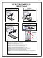
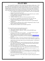
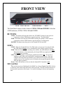
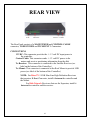
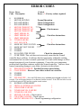
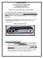
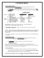
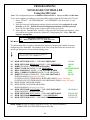
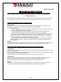
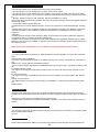
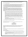
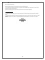
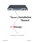
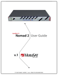
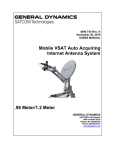
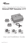
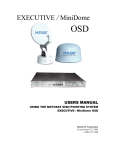
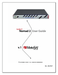
Satellite TV
Nomad SD2
USER GUIDE
Software Version 100 or higher
ALL RIGHTS RESERVED
901-Nomad SD2 Manual
Rev 4 Mar , ‘10
INDEX
DEFINITIONS
3
FEATURES
4
Front Panel description
Rear Panel description
5
6
OPERATION
Memory Card
Firmware Upgrade
Log Files
Error Messages
Error Codes
7
8
8
9
9
10
PROGRAMMING (Configuration)
Using the Front Panel
Using the SD Card
11
12
ROOT DIRECTORY EXPLANATION
14
Mount Definition
15
Sensors
16
Wire Schematic
17
Limited Warranty
18
MotoSAT Technical Support
19
2
MOUNT ROTATIONAL
DEFINITIONS
ELEVATION
AZIMUTH
(Raising of the dish from the stowed position)
(Rotation of the mount on the base plate)
SKEW
STOW
(Rotating or tilting of the dish from side to side)
(Travel Position)
Installation
Orientation
REAR
FRONT
COMPONENT AND FUNCTIONAL DEFINITIONS
Mount – Consisting of the dish and the mechanics to move the dish
Nomad SD2 - Positioner, Controller or Control Box
LNB – The device in front of the dish that receives the satellite signal
Control Cable – The 9 conductor cable that connects the Mount to the Nomad SD2
SD Card – The data storage device which provides software and configuration updates
Azimuth Motor – The motor on the mount that controls azimuth movement
Elevation Motor – The motor on the mount that controls elevation movement
Skew Motor – The motor on the mount that controls skew movement
Scotch Locks – The devices used to splice electrical wires within the mount assembly
BLUE LIGHT – The illumination of the dish face that signifies MotoSAT quality and excellence
LED – The lights on the front panel of the Nomad SD2 that indicates system status
Software – Code which instructs the mount to move, locate and identify satellites
Configuration – The instruction that tells the mount which satellites to identify. This can be accomplished from either from
either the front panel or with the use of the SD card
Log Files - Diagnostic files stored on the SD card for monitoring the system as it goes through its various routines
800-247-7486 – The number to call if you have any questions concerning your system operation
3
FEATURES
Your Nomad SD2 Controller has many features that make finding satellites easier. All of
the manual pointing and identification of your satellite antenna are taken care of by the Nomad
SD2. After your controller has been installed configured properly you have to only turn ON the
POWER and push either FIND (to send your antenna into a search for the proper satellite(s)) or
STOW to bring your antenna into the proper stowed position for traveling. Your controller has
many features that will assist you in acquiring and identifying satellites. Here are some of them:
• Fully configurable through the front panel or optional .dat file (see Programming
Using the Front Panel in this manual.)
• Software upgrades can be done using the SD Card provided with your controller
(see Programming Using the SD Card in this manual.)
• Controller operates on 12 VDC.
• Controller automatically shuts itself off when the antenna is stowed.
• New software is automatically detected when SD Card is placed into the
controller and loaded in 15 seconds after the power is turned on.
• Controller may be configured to operate any open faced TV system MotoSAT
manufactured.
• Controller may be configured to select satellite configurations for DirecTV, Dish
Network, SHAW Direct and Bell ExpressVu.
• GPS option may be added to assist in satellite acquisition.
The Nomad SD2 contains Operational Features such as:
• Two (2) button operation, FIND and STOW.
• LED Display to indicate LNB power, FIND, STOW and POWER status.
• Error Code displays.
• Automatic STOW feature on every system…… it is called “the first overpass”.
Just checking to see if you are reading the manual (smile.)
• Ability to take advantage of upgrades is software by going to www.motosat.com
and downloading new software onto an SD Card and putting it into your
controller.
• Return to Last Satellite. This feature eliminates the blind search that is required
when you have moved to a new location. Once you have found the satellite it will
simply return to that location after you have stowed the antenna. It will do this in
less than 3 minutes.
• Your open faced MotoSAT system will illuminate the dish with a soft blue glow
from a blue LED on the mount. It may be turned off after the antenna has been
deployed by turning off the Nomad SD2.
• Power does not have to be on to the controller once it has found satellite.
• No accidental deploying of the system. Power must be turned ON and then you
can select either FIND or STOW. The FIND button sends the antenna UP. The
STOW button puts the antenna DOWN.
• The antenna stows to a height of 10 ½ inches (below your air conditioner height.)
• A mounting plate that attaches to your roof will disperse the wind loading created
by the antenna during wind gusts.
• All of the electronics that control the antenna are located inside your RV.
• The system works off of 12 VDC with less than 3 amp draw during movement of
the antenna.
4
FRONT VIEW
STOW
FIND SD Card
Status Indicators
Power
The Front Panel consists of three buttons; STOW, FIND and POWER. It also has
4 LED indicators; STOW, FIND, LNB and POWER.
BUTTONS
STOW: This button will return the dish to the “STOWED” position. It also works in
conjunction with the FIND button to put the unit into “Test Dish Mode.”
FIND: This button will start the Nomad SD2 searching for satellite. It also works in
conjunction with the STOW button to put the unit into Test Dish mode.
POWER: This button turns the power to the Nomad SD2 ON and OFF.
LED’s
STOW: When the Nomad SD2 is in Test Dish mode or in process of stowing the dish,
this LED indicator blinks. It is on continuously when a dish is properly stowed.
FIND: When the Nomad SD2 is searching for a satellite, this LED indicator will blink.
When this indicator is ON continuously, the Nomad SD2 has completed its search
and is locked onto a satellite.
LNB: When the controller is searching for satellites this LED is ON. The power is
supplied to the LNB by the Nomad SD2 Controller during this time. Once the
controller has locked onto the satellite(s), the LNB receives its power from the
satellite receiver if the satellite receiver is linked to the mount through the Nomad
SD2 (this link is optional.)
Power: This LED indicates to the user that the Nomad SD2 Controller is ON.
SD Card Slot
This card slot receives a Multimedia Card (MMC) or a Secure Digital Card (SD). Push in
to insert the card. Push in then pull out to remove the card. The SD Card does not have to
be inserted for operation of the system. It is used for loading of software and capturing
data.
5
REAR VIEW
12 VDC
Control Cable
To Receiver To Mount
The Rear Panel consists of a MAIN POWER and CONTROL CABLE
connector, TO RECEIVER and TO MOUNT F-Connectors.
CONNECTIONS
12 VDC: This connector provides the +/- 12 volt DC input power to
the controller.
Control Cable: This connector sends +/- 12 volt DC power to the
motors and receives positioning information from the dish
To Receiver: This connector is connected to the Satellite Receiver (see
label on the bottom of the Controller.)
To Mount: This connector is connected to the Roof Mount to provide LNB
power (see label of the bottom of the Controller.)
NOTE: For DirecTV 5 LNB Slim Line High Definition Receivers
that require a B-Band Converter, install it between the controller and
the Mount.
For Dish Network Receivers that use the Separator, install it
between the controller and the receiver.
6
OPERATION
The following is a basic operation of the Nomad SD2 Controller.
POWER UP the Nomad
After making all the proper connections of the Nomad SD2 into the system, simply turn
on the power using the POWER button. The unit will initiate self test routines. This will take a
few seconds. The FIND and STOW LED’s will illuminate during this time to perform a lamp
test. If either one of these LED’s does not turn on during this time the unit should be repaired.
Once the initializing routine has finished, the front panel LED display will indicate the status of
the dish. The “FIND” LED will be illuminated if the dish is on satellite. If the “STOW” LED is
illuminated the dish is in the stowed position. If the “LNB” LED is lit the satellite receiver is
connected to the controller and has power to it. If the dish status is unknown, neither the FIND
nor STOW LED will be illuminated. In this case either stow the dish or perform a Test Dish
before proceeding.
TESTING the Dish
First time operation of the Nomad SD2 controller requires the user to execute a Test
Dish. To execute a Test Dish routine, turn ON the power and press the STOW and FIND buttons
simultaneously. The controller will perform a full test dish operation and determine the type of
mount that is being used. The STOW LED will flash during this operation. Once the Test Dish
operation is complete, the dish will be in the stowed position and the STOW LED will be
illuminated continuously. If the mount type conflicts with the current network configuration, a
critical error will be flagged and the unit will not operate. See “Memory Card” and
“Configuring” for more details. Two minutes after the completion of a Test Dish, the Nomad
SD2 will shut itself down automatically if there is no other activity.
FINDING a Satellite
To search for a satellite,
Press the FIND button once and the dish will read GPS, if installed, and begin to rise and
search for the desired satellite as defined by the network configuration or Return to Last Know
Satellite location. The FIND LED will flash during this time. Once the controller has locked on
satellite, the FIND LED will be illuminated continuously.
Press the FIND button once and then press it again and hold it for 3 seconds. This will
bypass Return to Last Known Satellite location. If the GPS has failed to read it will also bypass
the GPS and do a regular search routine.
STOWING the Dish
To stow the dish (place it into the travel position) press the STOW button once and the
controller will begin to return the dish to the travel position. The STOW LED will flash while
stowing. The STOW button can be pressed anytime during the search for and after locking on a
satellite. Once the dish is stowed, the controller will shut itself down automatically.
7
SD MEMORY CARD
The system will operate properly with or without the memory card inserted. The
card has two Functions.
1. Upgrading the latest firmware (obtained from www.motosat.com ) when it is
placed into the Root Directory.
2. Create and record data which will aid in troubleshooting (LOGFILES.) This
file is automatically created each time the system is stowed.
The card is inserted by pushing the card into the slot until it clicks into place.
To remove the card, depress the card once again and the socket will eject the it.
Then simply remove it the rest of the way. Never remove a card while the Disk
Busy LED is illuminated. Any MMC or SD Card can be used as long as it is
formatted to FAT32 file format.
STEPS TO PERFORM A FIRMWARE UPGRADE
1. The Nomad SD2 Controller can be upgraded manually by simply
copying the latest firmware upgrade into the Root Directory of the SD
memory card using a computer capable of utilizing SD Memory
Cards. Be sure to copy the file into the SD card "root directory" and
not into a subdirectory or folder. You can find the latest firmware
upgrade for the controller on our web site at: www.motosat.com.
2. Stow the dish.
3.
Power OFF the controller then insert the SD memory card into the
card slot in the front of the unit.
3.
Power ON the controller. The Nomad SD2 Controller will detect
the upgrade and automatically install the new upgrade code.
After a FIRMWARE UPGRADE is complete, a TEST DISH must be
performed. Failure to do so could result in the systems inability to perform
properly.
During the upgrade process, the FIND and STOW LED’s will flash alternately
indicating that programming is taking place. DO NOT remove the SD memory
card from the Controller until this process is complete. Completion is indicated
by steady FIND and STOW LED's. If no upgrade is detected or the upgrade is an
older version than what is already installed in the controller, an upgrade will not
take place. NOTE: The controller will not permit installing previous numbered
(older) upgrades. It will only recognize upgrades with a higher number than the
last one stored.
8
LOG FILES
Log Files are a diagnostic tool for monitoring the system as it goes through
its various routines. The Log Files are created in the Log Files directory folder
which is located in the root directory. If there is not a Log Files directory folder,
the Nomad SD2 will create one at initialization. The memory card must not be
write-protected for Log Files to be created and stored. If it is write-protected the
Nomad SD2 will ignore the card. The latest log File is the one with the highest
incremental number in the file name. To read a log file, simply open it using Word
Pad or any other Text Editor. The Controller creates a new Log File upon every
initialization and every time it locks on satellite.
ERROR MESSAGES
The Nomad SD2 has internal diagnostic capabilities that will indicate when
a Critical Error has been detected. If a critical error occurs, the STOW and FIND
LED’s will blink simultaneously with one second intervals. The number of
repetitions will indicate the specific number code of the error. After a two (2)
second pause the Nomad SD2 will blink out the error number again. The system
can not function after experiencing a critical error. The unit will have to be shut
OFF and restarted (see Test Dish.) The Nomad SD2 will also record a text message
indicating the error into the Log File provided an SD card was inserted at the time
of the error. If the card was not inserted at the time of the error simply turn OFF
the power and insert the SD card and turn ON the power to the Nomad SD2 and
press FIND. The system will produce a log file onto the SD card. This captured
information can be sent to the MotoSAT Technical Support Department to be
analyzed.
The following page has a list of each error, its number code, and whether or
not it is a critical error.
9
ERROR CODES
Error Error
Code Description
Critical
Error = ! (Factory action required)
0
NO ERROR
1
MOTOR, MOVING
Normal Operation
2
INVALID MODE 1
Check Configuration
3
INVALID MODE 2
Check Configuration
4
MOTOR, TIMEOUT EL
5
MOTOR, TIMEOUT AZ
Check sensors
6
MOTOR, TIMEOUT SK
7
LIMIT ERROR, EL
Check for obstructions
8
LIMIT ERROR, AZ
9
LIMIT ERROR SK
10
TUNER FAILURE
!
11
AGC, NO LOCK
!
12
MAIN SAT ONLY FOUND
Check for obstructions
13
MAIN SAT NOT FOUND
14
UNUSED
15
UNUSED
16
NO SATELLITES FOUND
Check for obstructions
17
OVER TEMP (This code does not necessarily mean that the Nomad
controller has a problem. It indicates that the temperature within the working
environment has exceeded a normal operational level and could damage or affect
normal operation of your electronic equipment. Correct the over temperature
problem and if problem continues replace the Nomad controller. You have been
warned concerning damage to your other electronics in the cabinet.
18
DISH HEIGHT ERROR - Possible Elevation sensor failure
19
COAX ERROR – Reverse Coax cables on back on controller
20
UNUSED
21
UNUSED
GPS FAILURE – Press the FIND button once and then press it again and hold it for 3
22
seconds. This will bypass Return to Last Known Satellite location. If the GPS has failed to read
it will also bypass the GPS and do a regular search routine.
23
24
25
26
27
28
29
30
NO MAIN AFTER SKEW
CRITICAL INTERNAL FAILURE
!
LNB POWER FAILURE
!
TUNER AMP ON, FAILURE
!
TUNER ID, FAILURE
!
MOTOR, FAILURE - Check sensors
COUNTER, FAILURE - Check sensors
MOUNT MISS-MATCH – Check Programming configuration
10
PROGRAMMING
NOMAD SD2 CONTROLLER
Using the Front Panel
(With Version 29 Software or greater)
This process is only needed to be done once per installation.
CAUTION!! Do not confuse this software with any earlier versions. If you
have a NomadSD.dat file on your SD Card Remove it from the Root Directory
FIRST. Failure to do so will cause your Configuration that is stored on the
NomadSD.dat file to remove any programming that you may do through the
front panel.
The Nomad SD2 Controller can be programmed in simple and easy steps. The
STOW/FIND and the POWER buttons will allow you to configure your
controller properly.
NOMAD SD2 CONTROLLER
STOW
FIND
POWER
Entering into the Configuration Mode
• Hold down the STOW and FIND buttons and while continuing to hold,
turn the power on using the POWER ON button. Release the POWER
button but continue to hold the STOW and FIND buttons for an additional
10 seconds or until you see the STOW and FIND LED’s turn OFF, then
turn ON again then release. You are now ready to proceed. If that does not
happen, repeat the above process until it does. This will put the controller
into the Configuration mode (similar to what you do or have done with the
Nomad 2/3 Controller to enter into the Programming Mode.)
11
CONFIGURING
To SET SERVICE TYPE
(Pressing the FIND BUTTON will toggle through SERVICE TYPE.)
•
Slow Blink
Rapid
Blink
The FIND LED indicates the Network ID (or SERVICE TYPE) selected. It will blink
the number of the current settings, pause, and the repeat the pattern according to the
following table:
MOUNT TYPES
SERVICE TYPE
NON SKEWABLE * SKEWABLE *
1= Dish Network
119/110
110,119
2= DirecTV
101
99,101,103,110,119
3= Bell Express Vu
91/82
82,91
= SHAW DIRECT SEE “SHAW DIRECT CONFIGURING”**
5= Dish Network EAST
61.5/110/119
N/A
6= Dish Network WEST
110/119/148
N/A
7= DirecTV ENHANCED
101/119
N/A
8= Dish Network HD
110/119,129
110,119,129
Show Mode can only be entered using the SD Card. See PROGRAMMING
NOMAD SD2 CONTROLLER Using the SD Card
**SHAW DIRECT CONFIGURING – SIMPLY LOAD SOFTWARE REVISION 1000 OR HIGHER.
CONFIGURING IS AUTOMATIC.
*NOTE: A slash (/) between the satellites indicates the system will only see one satellite at a
time. A comma (,) between the satellites indicates the system will see all these satellites at
the same time.
Once eight (8) rapid blinks is reached the process will start back at one (1) if the FIND button is
pressed again.
To SET MOUNT TYPE
(Pressing the STOW BUTTON will toggle between Skewable and
Non-Skewable mount configurations.)
The STOW LED will indicate Skewable or Non-Skewable type mounts
Skewable = ON,
Non-Skewable = OFF.
Please note: In the case of Dish Network EAST, Dish Network WEST and DirecTV
ENHANCED or a Star Choice mount the STOW LED will automatically be set according to the
type of mount used for that particular type of configuration.
•
SAVING SETTINGS
• To save the current configuration setting, turn off the unit and turn it back on again
normally and that will store your settings. At this time please perform a TEST DISH to
match the Controller to the Mount. After a successful Test Dish….
PRESS THE “FIND” BUTTON TO ACQUIRE YOUR PROGRAMMED SATELLITES.
12
PROGRAMMING
NOMAD SD2 CONTROLLER
Using the SD Card
Note: This configuration process is limited to Microsoft PC’s. Sorry, no Mac’s at this time.
To use your computer to configure your Nomad SD2 simply format the SD card to FAT32 and:
1. Select “START”, “ALL PROGRAMS”, “ACCESSORIES” and “Note Pad” on your
computer.
2. Enter the Network Configuration number from the selection below and place it on the
first line of the file. Just the Network Configuration number is all that you need.
Note: The Freedom Dome system requires special code (see below)
3. Name this file “NomadSD.dat” and save it onto your SD Card in the root directory. Once
it is used be sure to place it into the “MotoSAT Configuration File” folder. This will
improve startup time.
This sample configuration is set for
003
003
DIRECTV HD SL5 MODE, 5 LNB, SKEWABLE DISH
The information below is used for obtaining the Network Configuration Number for proper
configuring of the NomadSD. The numbers in the first column determine the Network and
mount type being used. Always include leading zeros.
Note: NON SKEWABLE dishes will have a single LNB.
SKEWABLE dishes will have multiple LNB’s.
000
001
002
003
004
005
006
011
012
014
016
017
018
119-110
DISH NETWORK MODE, 1 LNB, NON SKEWABLE
110/119
DISH NETWORK MD500 Style MODE, 2 LNB, SKEWABLE
DIRECTV MODE, 1 LNB, NON SKEWABLE
101
DIRECTV HD-SL5 MODE, 5 LNB, SKEWABLE
99/101/103/110/119
BELL EXPRESSVU MODE, 1 LNB, NON SKEWABLE
91-82
BELL_EXPRESSVU HD DP3 MODE, 3 LNB, SKEWABLE
91/82
DIRECTV ENHANCED MODE, 1 LNB, NON SKEWABLE
101-119
BURN IN MODE, 18 (Factory Use Only)
CONTINUOUS TEST DISH MODE, SKEWABLE DISH (Factory Use Only)
CONTINUOUS TEST DISH MODE, NON SKEWABLE DISH (Factory Use Only)
SHOW MODE, SKEWABLE DISH
SHOW MODE, NON SKEWABLE DISH
BURN IN MODE, 8 (Factory Use Only)
DISH NETWORK EAST MODE, 1 LNB, NON SKEWABLE
119-110-61.5
BURN IN MODE, 4 (Factory Use Only)
DISH NETWORK WEST MODE, 1 LNB, NON SKEWABLE
110-110-148
DISH NETWORK HD-DP3 MODE, 3 LNB, SKEWABLE
110/119/129
DISH NETWORK MODE, 3 LNB, NON SKEWABLE
119-110-129
Show Mode can only be entered using the SD Card. See PROGRAMMING
NOMAD SD2 CONTROLLER Using the SD Card
13
EXPANATION
SD Card Root Directory
NomadSD.dat
These two (2) files (.hex and .dat) are considered to be
in the “root Directory”
NOTE:
The .hex file contains the operating program of the
Nomad SD2 and once read it will be stored into the Nomad SD2
memory.
The .dat file contains the information to let the Nomad
SD2 know what type of mount it is attached to and what satellites
the mount is supposed to find. Once read it will be stored into
the Nomad SD2 memory.
After the Nomad SD2 is first turned on it is not necessary to have
these files in the root directory. They may be moved into the
MotoSAT files folder or a folder of your choosing
There are no files in the “root Directory”
14
MOUNT DEFINITION
Motors and Sensors
(Azimuth, Elevation)
Mounting Plate
Elevation
Sensor
Azimuth
Sensor
Mount (HD)
Skew Motor and Sensor
Skew
Sensor
LNB Arm (HD)
When replacing a motor, improper handling can result
in this…... Tape the motor gear housing together to
prevent separation. Motors returned in this condition
will be charged a fee.
15
SENSORS
All Sensors for the television mounts utilize the same sensor. It can be used in the
Azimuth, Elevation or Skew motor assemblies.
5 ½ threads
Depth into the gearbox assembly is
important. The lock nuts are in
place to keep the sensor at the proper
predetermined depth. A good rule of
thumb is 5 ½ threads from the end of
the sensor to the first nut.
NOTE:
1. The depth of the sensor is common for all television motor assemblies.
2. Use care in handling the sensor. Do not pry or put into a bind as breakage can occur.
The sensor is actually a glass bead encapsulated into plastic.
3. When handling motors use care as the case can separate causing the motor gearbox
housing to come apart and prove to be unusable.
4. Scotch Locks are splicing devices which will aid in sensor replacement when used
properly.
5. Take care in locating the proper wire to splice. Do not mistake the motor wire for the
sensor wire. See Wiring Diagram
16
17
Effective 23 April 2008
3-YEAR LIMITED WARRANTY
FOR NEW SYSTEMS PURCHASED AND INSTALLED THROUGH A CERTIFIED DEALER
DETAILS BELOW
MotoSAT designs and manufactures high quality equipment and makes every effort to insure that you are getting
the most reliable product available. In the event your product should fail please follow the guidelines set below.
90-DAY SERVICE AND FREIGHT WARRANTY GUIDELINES
90 DAY SERVICE
• MotoSAT will cover in the first 90 days from date of installation pre-approved dealer piece rates for removal,
reinstallation and alignments of any defective component manufactured by MotoSAT.
• Conditions of the warranty:
o Customer agrees to take his vehicle to an approved MotoSAT service center or agrees to pay the travel
time for the approved MotoSAT Service Technician.
o The service appointment must be pre-approved by the MotoSAT Warranty/Support Department.
o All reasonable charges have been discussed and accepted, in advance, by both parties.
o New parts received for installation and found to be non-functional at the time of installation can be sent
back to MotoSAT for a full exchange and compensation for time and shipping when part is verified by
MotoSAT to be non-functional. If said part is found to be fully operative and functional, no compensation
for time will be approved and shipping will be charged both directions.
o If during repair the Service Technician discovers that failure is due to either damage after installation or
improper installation the Service Technician will contact MotoSAT Technical Support Department for
further instruction.
FREIGHT
• MotoSAT agrees to pay ground freight ONLY, in both directions, for replacement parts and components in the first
90 days of Warranty. Any other requested method of shipping will be at the sole expense of the customer.
1 YEAR FACTORY LABOR, 3 YEARS PARTS AND FREIGHT WARRANTY GUIDELINES
1 YEAR LABOR
• MotoSAT will cover factory labor rates on all new equipment and components manufactured by MotoSAT for 1 year
from the date of installation.
• After 1 year from the date of installation all equipment and components manufactured by MotoSAT will be charged
pre-set factory labor rates for repair or replacement.
• Refer to the MotoSAT RMA policy at the end of this warranty for part replacement options.
3 YEARS PARTS
• MotoSAT will cover all new equipment and components manufactured by MotoSAT to be free from defects in
material and workmanship under conditions of normal use for 3 years from the date of installation.
• Refer to the MotoSAT RMA policy at the end of this warranty for part replacement options.
FREIGHT
• After 90 days, MotoSAT agrees to pay for ground freight ONLY, in one direction, for replacement parts and
components. Any other requested method of shipping will be at the sole expense of the customer.
18
WARRANTY EXCLUSIONS AND LIMITATIONS
XCLUSIONS AND LIMITATIONS
• This warranty extends only to the Original purchaser and is not transferable
• This warranty does not cover damage due to accident, misuse, abuse, neglect.
• This warranty does not cover damage due to wind, lightning, power surges, fire, flood or any other act of nature.
• This warranty does not apply to any component or product not manufactured by MotoSAT, included but not limited
to:
o Modems, (IRU/ITU), feed horn, LNB, transmitter, dish face and Satellite TV receiver.
• All components not manufactured by MotoSAT are subject to separate warranties issued by the Original Equipment
Manufacturer (OEM).
o Hughes.Net, Prodelin, UnaSat, IDirect, etc.
• MotoSAT shall in no event be liable for damage to or loss of any equipment or consequential damages. Including
but
not limited to damages to other equipment resulting from the installation or operation of the MotoSAT components.
• This warranty does not cover installation by Dealers or individuals who are independent contractors and not
employees
of MotoSAT.
• MotoSAT reserves the right to make changes in design or improvements in its products without the obligation to
incorporate the same in any product previously manufactured.
• MotoSAT internet system and equipment must be initially installed and/or upgraded by MotoSAT factory certified
Installers. In the event system installation or upgrade is not preformed by a MotoSAT certified installer all warranty on
said equipment is void.
NOTE: Consult your dealer/installer for any installation warranty provided by the dealer/installer.
WARRANTY SERVICE
• To receive the benefits of this warranty you must complete the enclosed registration form and mail it to MotoSAT
within
30 days from the date of installation.
• Our Internet Technical Support Department is available 24 hours a day 7 days a week at 800-247-7486, listen for
your
options for day, evening and after hours/weekend support.
• Our TV Technical Support Department is available Monday through Friday from 8am – 5pm (MST) at 800-247-7486
ask
for Satellite Television support.
• For support concerning your Internet Service please contact your VAR or ISP, these are the companies you are
paying
for your internet service.
• For support concerning your Satellite Receiver please contact your Satellite TV provider; DirecTV, Dish Network,
Bell
Express VU or Star Choice.
• For additional after hours support or issues relating to the installation or operation of this product please contact
your
installing dealer.
EXPIRED WARRANTY
• MotoSAT offers replacement parts, technical support troubleshooting tickets, support warranties and extended
warranties for all out of warranty customers at a fair price. Please contact MotoSAT Technical Support for assistance
in
determining your best options and available pricing for these services.
• MotoSAT does not cover the cost of removal, reinstallation, alignment or any other service performed under this
warranty.
WARRANTY EXTENSIONS AND SERVICE CONTRACTS
• For information concerning extended warranties and service contracts that can be tailored for your individual needs
please contact MotoSAT support.
4/23/2008
MotoSAT RMA POLICY
Return material Authorizations (RMA’s) may be issued by the MotoSAT technical support and sales departments.
19
MotoSAT factory certified dealers/installers may request RMA’s via Email and phone at there discretion with or
without troubleshooting assistance understanding they are subject to same terms and conditions below.
RMA’s have 3 designation subsets.
1. RA = Repair and Return: The customer sends in the defective part or product and we repair it in house and
return it to them. Depending on the customers warranty status we may charge them for the price of the
component and/or the labor cost to repair it sometimes including shipping costs. This allows for MotoSAT to
determine exactly what the problem is and enhance product to avoid the same issues in the future
2. RS = Return Swap: MotoSAT sends the customer a replacement part and after the customer has changed
out the part, they then return to us the “core” item that is perceived to be defective. MotoSAT will only offer
this option if the customer is within warranty and willing to provide a credit card to guarantee return
shipment of the bad part.
The RS designation is a convenience to the customer and in consideration of this convenience the
customer needs to accept full liability for this type of RMA. When it is determined that a customer needs a
part replacement MotoSAT support will read an exact script (Appendix A) of terms and conditions and
expect the customer to verbally agree to the terms and conditions before sending the part. The support
agent will also add the acceptance to the customer’s notes in our warranty database. These same terms
and conditions will be sent in writing with each part shipped as an RS. The terms and conditions will reflect
the following:
A. If the customer wishes to receive the item in advance they will be required to acknowledge that
they were instrumental in diagnosing probable issues with the item and if the item is found to be
without defect, the customer will be liable for all shipment costs and a 25% restocking fee of the
Item.
B. If the customer wishes to receive the item in advance they will be required to provide a credit
card number to ensure return of the original item that is perceived to be defective. The customer will
be given 10 business working days to return the item beginning with the day it is received by the
customer from MotoSAT. If on the 11th business working day after the item is received by the
customer from MotoSAT the “core part” has not been received by MotoSAT from the customer, the
customer will be charged for the full retail value of that item to the credit card given. Customers
requiring International shipping may be an exception to this rule and dealt with on a case by case
basis.
C. In the case of a dealer requesting an RS a credit card will not be required if the dealer has credit
terms with MotoSAT.
D. If the Customer can not agree to all the terms and conditions of receiving an RS (item in
advance) they will be directed to use the RA option.
3. RN = Part Sent no return required: This occurs in the case of misc. nuts and bolts plastic pieces etc. that
would not help MotoSAT in any way if the item was returned.
Any item being returned to MotoSAT must be properly packaged and addressed including return material
authorization (RMA) number to:
MotoSAT
Attn: Technical Support
(place RMA number here)
1955 S. Milestone Dr.
Salt Lake City, UT 84104
Note: Items received without RMA numbers clearly marked on the outside of the package could experience
receiving delays. MotoSAT does not accept responsibility for these delays. In the event this item is an RS
designation the customer is still liable for RS terms and conditions mentioned in part 2.B. above.
4/23/2008
Appendix A
Our Phone support technicians will follow the script below to ensure there is no misunderstanding in regards to our
RS RMA designation.
“For your convenience MotoSAT offers to send you replacement parts in advance under the condition that you
agree to the following terms.
- You agree to provide MotoSAT with a valid credit card to guarantee return shipping of the original item. If
the item is not returned to MotoSAT within 10 business working days beginning with the day it is received.
You may be charged for the full price of the item.
- You agree that you have been instrumental in diagnosing probable issues with your system and
understand
that if the item being returned has no defect, you may be subject to further shipping charges and restocking
20
fees.
Will you agree to these terms?”
[Customers willing to agree to the terms will also receive the following script:]
“To help avoid further charges and shipping costs, please ensure the RMA number I will provide you with is clearly
marked on the outside of the package”.
[Customers unwilling to agree to theses terms will be directed to follow the RA designation.]
MISREPRESENTATIONS
• MotoSAT has not authorized anyone to make representations or warranties other than the warranties contained
herein.
• This warranty gives the purchases specific legal rights which may vary from state to state. Some states do not allow
exclusion of limitations of incidental or consequential damages or allow limitations on the duration of an implied
warranty.
MotoSAT
1955 S. Milestone Dr.
Salt Lake City, UT 84104
www.motosat.com
1.800.247.7486
21
Notes
Date of Purchase________________
DD / MM / YY
Installing Dealer __________________________________
Telephone Number ______/_____/_________
System Model Number ________________________
Serial Numbers ____________ ________________
Repairs ________________________________________
_________________________________________
_________________________________________
_________________________________________
Version of Software
Date ___________ Rev. No. ________
Date ___________ Rev. No. ________
Date ___________ Rev. No. ________
22
For additional information at this time contact
MotoSAT Technical Support @ 800-247-7486
The MotoSAT Technician will ask you
1. What is your of Mount “Type” (Skewable or Non-Skewable)
2. What “Service” do you subscribe to
3. If you feel that it is a Warranty problem then be sure that you have
your system registered before you call else it will be treated as a nonwarranty situation.
Thank you for your assistance,
Your Friends at MotoSAT
MotoSAT
1955 South Milestone Dr.
Salt Lake City, UT 84104
Tele 800-247-7486
Fax 801-972-5407
www.motosat.com
23