1
Control Panels
Power Supply and Power Outputs | en
21
Available Power
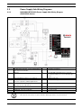
The system combines the 1.4 A of primary power produced by the power supply with the
secondary power source (the battery) to produce a total of 2.0 A of alarm power at 12.0 VDC
Nominal. Terminals 6 and 7 share the available alarm power.
Power Restricted for Fire and Combined Fire and Burglary Systems
Fire systems are prohibited from using the battery for determining alarm power. Use the fire
system power formula described in Section 3.6.3 Fire System Power Formula, page 21 to
calculate the current available for fire and combined fire and burglary systems.
3.6.3
Fire System Power Formula
To calculate the current available at Terminals 6 and 7 for fire and combined fire and burglary
systems:
1.
Add together the current draws for all devices connected to Terminals 3, 8, 24, and 32,
and the accessory connector. This is the total current required for the normal standby
condition (NSC).
2.
The current available for NSC is 1.4 A. Subtract the NSC current required calculated in
Step 1 from the NSC current available, 1.4 A. The difference is the alarm current available
for Terminals 6 and 7.
In formula format:
1.4 A - NSC current required (Step 1) = Alarm current available
Refer to the D9412GV3/D7412GV3 Approved Applications Compliance Guide (P/N:
F01U143069) or the D7212GV3 Approved Applications Compliance Guide
(P/N: F01U143080) for module or accessory current requirements.
3.6.4
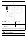
Terminal 8
Terminal 8 provides continuous positive (+) 12.0 VDC Nominal power. Relay C interrupts the
power at Terminal 8 when activated. Use Terminal 8 to power smoke detectors or other
devices that are reset by interrupting power. One self-resetting circuit breaker protects
Terminals 6, 7, and 8 against shorts.
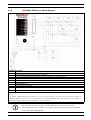
Verification/Reset Relay
The default program sets Relay C (Terminal 8) as a verification and reset relay. Refer to Relay
Parameters and Point Assignments in the D9412GV3/D7412GV3 Program Entry Guide (P/N:
F01U170807) or in the D7212GV3 Program Entry Guide (P/N: F01U170808) for instructions on
programming verification/reset relays and points.
Performing a sensor reset at a keypad produces a five-second relay activation of verification/
reset relays. The control panel ignores verification and reset points during the five-second
relay activation.
Bosch Security Systems, Inc.
UL Installation Instructions
F.01U.167.105 | 02 | 2010.11