1
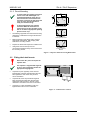
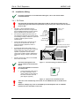
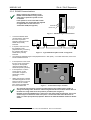
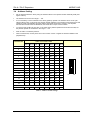
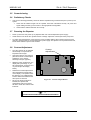
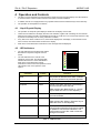
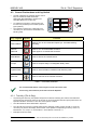
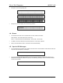
ZXr-A
ZXr-P
Document No. 996-144 Issue 02
operation &
installation
manual
MORLEY-IAS
ZXr-A / ZXr-P Repeaters
Table of Contents
1
INTRODUCTION ......................................................................................................................... 3
1.1
1.2
1.3
NOTICE .................................................................................................................................. 3
WARNINGS AND CAUTIONS ...................................................................................................... 3
NATIONAL APPROVALS ............................................................................................................ 3
2
DESCRIPTION ............................................................................................................................ 4
3
INSTALLATION .......................................................................................................................... 4
3.1
MOUNTING THE REPEATER TO THE WALL ................................................................................. 5
3.1.1
Using the Bezel Kit........................................................................................................ 5
3.1.2
Direct Mounting ............................................................................................................. 6
3.2
FITTING THE LABEL INSERTS ................................................................................................... 6
3.3
INSTALLATION WIRING ............................................................................................................ 7
3.3.1
DC Power...................................................................................................................... 7
3.3.2
RS485 Communications ............................................................................................... 8
3.4
ADDRESS SETTING ................................................................................................................. 9
3.5
COMMISSIONING ................................................................................................................... 10
3.6
PRELIMINARY CHECKS .......................................................................................................... 10
3.7
POWERING THE REPEATER ................................................................................................... 10
3.8
CONTRAST ADJUSTMENT ...................................................................................................... 10
4
OPERATION AND CONTROLS ............................................................................................... 11
4.1
LIQUID CRYSTAL DISPLAY ..................................................................................................... 11
4.2
LED INDICATORS.................................................................................................................. 11
4.3
CONTROL PUSHBUTTONS AND KEY SWITCH ........................................................................... 12
4.3.1
Test Key (ZXr-A Only)................................................................................................. 12
4.4
BUZZER ............................................................................................................................... 13
4.5
SPECIAL LCD MESSAGES ..................................................................................................... 13
5
SPECIFICATIONS .................................................................................................................... 14
Table of Figures
FIGURE 1 - BACK BOX FIXING AND APERTURE DIMENSIONS ..................................................................... 5
FIGURE 2 - EARTH CONNECTIONS .......................................................................................................... 5
FIGURE 3 - REPEATER ENCLOSURE FIXING DIMENSIONS ......................................................................... 6
FIGURE 4 – LABEL INSERT LOCATIONS ................................................................................................... 6
FIGURE 5 – EXTERNAL WIRING TERMINATION POINTS ............................................................................. 7
FIGURE 6 – SAFETY EARTH TERMINATION POINT .................................................................................... 7
FIGURE 7 – RS485 RE-LEGEND LABEL POSITION .................................................................................... 8
FIGURE 8 – TYPICAL RS485 PERIPHERAL LINK ARRANGEMENT ............................................................... 8
FIGURE 9 – TERMINATION JUMPER POSITIONS ........................................................................................ 8
FIGURE 10 – CONTRAST ADJUST BUTTON ............................................................................................ 10
Table of Tables
TABLE 1 - ADDRESS SWITCH SETTINGS .................................................................................................. 9
TABLE 2 - LED FUNCTIONS.................................................................................................................. 11
TABLE 3 – CONTROL KEY FUNCTIONS .................................................................................................. 12
TABLE 4 - ZXR-A / ZXR-P REPEATERS SPECIFICATIONS ....................................................................... 14
Page 2 of 16
Document No. 996-144, Revision: 02,
Operation & Installation Manual
ZXr-A / ZXr-P Repeaters
MORLEY-IAS
1 Introduction
1.1
Notice
•
The material and instructions covered in this manual have been carefully checked for accuracy and are
presumed to be correct. However, the manufacturer assumes no responsibility for inaccuracies and
reserves the right to modify and revise this document without notice.
•
These instructions cover the operation and installation of the ZXr-A / ZXr-P Repeaters. Refer to the Fire
Alarm Control Panel (FACP) Manuals for instructions on powering up, operating and programming the
system. ZXr-A / ZXr-P Repeaters can be used on systems installed with ZXr4B / ZXr5B repeaters and
there are no known compatibility issues.
1.2
Warnings and Cautions
These instructions contain procedures to follow in order to avoid injury and damage to
equipment. It is assumed that the user of this manual has been suitably trained and is
familiar with the relevant regulations.
All equipment is to be operated in accordance with the appropriate standards applicable
This panel is CE Marked to show that it conforms to the requirements of the following
European Community Directives:
EN54
!
•
•
Electromagnetic Compatibility Directive 89/336/EEC (and the amending directive
92/23/EEC)
•
Low Voltage Directive 73/23/EEC
The ZXr-A / ZXr-P Repeaters have been designed to comply with the requirements of
EN54-2:1997, when used as a secondary display.
EN54-2 12.5
EN54
!
Integrity of
transmission paths:
The peripheral link
does not provide
the required
transmission path
integrity.
1.3
•
The ZXr-A / ZXr-P Repeaters are connected to the FACP via the
“Peripheral Loop” 2-wire RS485 communications circuit.
•
Refer to the FACP installation manual for further information and
for recommended cables.
National Approvals
This equipment must be installed and operated in accordance with these instructions and the
appropriate national, regional and local regulations specific to the country and location of the
installation. Consult with the appropriate Authority Having Jurisdiction (AHJ) for confirmation of the
requirements.
Operation & Installation Manual
Document No. 996-144, Revision: 02,
Page 3 of 16
MORLEY-IAS
ZXr-A / ZXr-P Repeaters
2 Description
•
The Remote Repeater provides an extension to
the operation of the Fire Alarm Control Panel
(FACP). Both types of Repeater show (repeat)
the operational state of the FACP using the 2x40
LCD and the LED indicators.
•
The ZXr-P Passive Repeater will only show
(repeat) the operational state of the FACP.
•
The ZXr-A Active Repeater will show (repeat) the
operational state of the FACP and can control
the FACP using the SOUND ALARMS, SILENCE
/ RESOUND, MUTE BUZZER, ACCEPT and
SYSTEM RESET functions.
•
The Repeaters are connected to the FACP via
the Peripheral Bus RS485 data link. The FACP
supervises the ZXr-A Active Repeater. A Fault
will be indicated, at the FACP, if communications
is lost with the Repeater.
•
The ZXr-A / ZXr-P Repeaters are compatible with
the ZX1e, ZX2e, ZX5e and older ZX Range of
1
Fire Alarm Control Panels .
•
An optional Bezel Kit, containing back box and
bezel, is available for pre-installation (P/N 002600-002).
•
The ZXr-A has in-built self-test functions that can
be invoked using the buttons. The LCD contrast
can be adjusted on both repeaters.
ZXr-A (Active Repeater)
ZXr-P (Passive Repeater)
3 Installation
Ensure that the operating ambient temperature is in the recommended range +5°C to
+35°C and that the relative humidity is between 5% and 95%. DO NOT locate the repeater
where it may be exposed to high levels of moisture, vibration or shock.
This equipment contains transient protection devices. Although no system is completely
immune to lightning transients and interference, for these devices to function correctly,
and to reduce susceptibility, this equipment MUST be earthed correctly. As with all solidstate devices, this system may operate erratically or can be damaged if subjected to
lightning induced transients. The use of overhead or outside aerial wiring is not
recommended due to the increased susceptibility of nearby lightning strikes.
•
The installation process consists of 4 steps, as follows:
1.
Mount the Bezel Kit (if required) OR fix the enclosure to the wall (if Bezel Kit is not required)
2.
Fit the label inserts
3.
Install and connect the wiring and set the repeater’s address
4.
Perform the commissioning checks
Before attempting to install the ZXr repeater, remove it from the packaging and inspect for
any damage that may have occurred during transit. In the unlikely event that damage has
occurred, DO NOT install the repeater but return it to the supplier using the original
packaging.
1
ZX Series comprises ZX1e, ZX2e, ZX5e, ZX1, ZXa, ZXe and ZXMi-EN. Does not include ZX50.
Page 4 of 16
Document No. 996-144, Revision: 02,
Operation & Installation Manual
ZXr-A / ZXr-P Repeaters
3.1
MORLEY-IAS
Mounting the Repeater to the Wall
•
The ZXr repeater should be wall mounted in a position that allows clear visibility of displays and easy
access to operating controls. The height above floor level should be chosen such that the LCD is just
above normal eye level (approximately 1.5 metres).
•
DO NOT site the ZXr repeater where there would be restricted access to the internal equipment and
cabling / wiring connections.
3.1.1 Using the Bezel Kit
307
263
Support the bezel / back box assembly in the
desired position in the recess and mark the three
screw fixing positions (X) as shown opposite.
Remove the assembly from the recess. Using an
appropriate sized drill bit, drill and plug the three
holes to take up to No. 8 (4mm) wood screws.
Alternatively, use the side fixing holes (Y).
219
88
110
22
22
58
92
X
X
218
X
Y
Y
Side View
Rear View
90
267
Depth
Height & Width
179
•
Make a recess in the wall large enough for the back
box to be inserted easily and without unnecessary
force. Allow for space required for cable entry into
the back box. With the bezel still attached to the
back box, offer the assembly to the recess to check
for correct depth and clearance. Repeat this
process until the correct depth and clearance have
been achieved.
Bottom View
175
•
The Bezel Kit is supplied with a dedicated back box
that has three fixing holes on the rear wall and two
fixing holes on each side. This procedure covers the
use of the rear fixing holes but can be applied to the
side fixings.
130
•
Recommended Aperture Dimensions
Figure 1 - Back Box Fixing and Aperture
Dimensions
To avoid distortion of the back box
when preparing knockouts, place the
appropriate back box face on a
supporting surface (e.g. work bench).
•
Prepare all required knockouts and fit cable glands
as required (Refer to Wiring Installation Section).
•
Orientate the bezel / back box assembly correctly, off it to the recess, then feed the cables through the
glands and take up any excess slack. Secure the assembly in position using appropriate sized screws –
do not use countersunk-headed screws. To avoid distorting the back box, do not over tighten.
•
Prepare the repeater for fitting by removing the appropriate knockouts as required. Insert one of the
supplied cable grommets into the upper knockout on the rear wall of the repeater (this knockout is
required / used for an earth connection).
•
Correctly orientate the repeater, hold the door open and off the repeater to the installed bezel / back box
assembly. Feed all cables through the prepared knockouts and full insert the repeater into the bezel /
back box aperture. Use the four M4 SEM screws supplied in the kit to secure the repeater to the
assembly (for location of the repeater mounting holes, refer to the Direct Mounting instructions below).
•
Connect the free end of the back box earth lead to the earth
connector provided on the inside of the repeater enclosure (top
left corner). Use a suitably sized cross-headed screwdriver to
tighten at the earth point. Ensure good connection is made.
Top Left of Enclosure
Figure 2 - Earth Connections
Operation & Installation Manual
Document No. 996-144, Revision: 02,
Page 5 of 16
MORLEY-IAS
ZXr-A / ZXr-P Repeaters
3.1.2 Direct Mounting
253
20
126
161.5
To prevent distortion, the repeater
enclosure MUST be mounted on a
surface that is as flat a possible. If the
wall is not flat use appropriate packing
pieces to level it up.
•
Mark the position of the fixing holes. Using an
appropriate sized drill bit, drill and plug three
holes in the mounting surface.
•
Prepare the knockouts required for cable access.
•
Using three 5mm screws (do not use
countersunk headed screws), fix the enclosure to
the mounting surface.
51
Template for Mounting
Repeater Directly to Wall
The drawings opposite show the enclosure fixing
dimensions in millimetres. Fixing holes are 5mm
in diameter.
•
165
130
To ensure that the repeater electronics
remain clean and undamaged, it is
recommended that the front door of
the enclosure be covered before the
enclosure is fixed to the wall. Keep the
cover in place until the repeater is
ready for commissioning.
Use these holes if
mounting Directly on Wall
Use these holes if
mounting in Bezel Kit
Back Box
Figure 3 - Repeater Enclosure Fixing Dimensions
3.2
Fitting the Label Inserts
Disconnect ALL power and open the
repeater door.
The repeater is supplied with legends
in one or more languages. Select the
appropriate language set.
•
At position A (see opposite), insert the LED
legends label. Fold the perforated line (the fold
rests against the side of the door). Ensure
correct orientation.
•
At position B, insert the push button legends
label. Fold the perforated line (the fold rests
against the side of the door). Ensure correct
orientation. This label is not used on the ZXr-P.
•
C
B
A
At position C, insert the MORLEY-IAS logo
legend label. Ensure correct orientation.
Figure 4 – Label Insert Locations
Page 6 of 16
Document No. 996-144, Revision: 02,
Operation & Installation Manual
ZXr-A / ZXr-P Repeaters
3.3
MORLEY-IAS
Installation Wiring
For further information on recommended cable types, refer to the relevant FACP
Installation Manual.
3.3.1 DC Power
Only terminate the repeater power cables at the FACP or external source after ALL precommissioning checks have been performed. Only connect power cables when the system
power is OFF.
•
•
•
The ZXr-A / ZXr-P Repeaters must be
supplied with DC Power from an approved
and compatible regulated 24-Volt DC Power
Supply, suitable for Fire Protection use.
If dc power is supplied from the FACP, do
not exceed the maximum AUX current rating
or the battery standby conditions in quiescent
or alarm conditions (refer to FACP
specifications).
Connect the DC Power to the 28V IN (1832V dc) and 0V IN terminals, from the
previous repeater, peripheral, FACP or
external source.
•
If required the DC Power Supply can be
daisy chained on to the next unit on the loop.
Connect 28V OUT and 0V OUT to next
repeater or peripheral. Ensure that the
correct size of cable is used to maintain the
required DC Supply Voltage at the furthest
unit
•
DO NOT connect any wires to the POWER
FAIL and 0V terminals.
The terminal designations are
clearly marked on the Connection
Board.
0V IN
28V IN
0V OUT
28V OUT
0V
POWER FAIL
RS485 IN
RS485 OUT
RIBBON CABLE
(INTERNAL)
0V
28V
0V
28V
0V
PF
A
B
A
B
Connect Power Cable
Earth (Cable Shield) to
Safety Earth Point
OPTIONAL RIBBON
CABLE
(INTERNAL RS232
BOARD)
Route cables as shown and tie
down to enclosure using cable
ties to positions provided
Figure 5 – External Wiring Termination Points
The enclosure MUST be connected
to a safety earth.
•
Connect the safety earth wire to
the safety earth point. This is
clearly marked on the inside top
left of the enclosure rear wall
(see diagram opposite).
Top Left of Enclosure
Figure 6 – Safety Earth Termination Point
Take care not to inadvertently connect the ‘A’ & ‘B’ RS485 terminals to the DC Power
Supply.
Otherwise, damage may occur to the RS485 input of the Repeater and / or to RS485
Interface Circuit in the FACP or other unit.
Operation & Installation Manual
Document No. 996-144, Revision: 02,
Page 7 of 16
MORLEY-IAS
ZXr-A / ZXr-P Repeaters
3.3.2 RS485 Communications
Before commencing installation of the
RS485 communications wiring, check to
which type of panel the repeater is to be
connected.
If the repeater is to be connected to a ZX 2
Series FACP, peel off and affix the supplied
re-legend label over the text on the
Termination PCB (see opposite).
0V
28V
0V
28V
0V
PF
RS485 IN
B
A
B
A
RS485 OUT
For ZX Line, Place
supplied label here
over existing text.
Figure 7 – RS485 Re-legend label Position
•
•
Connect the RS485 serial
communications wires from
the FACP or previous
repeater / peripheral to the
RS485 IN (A and B)
terminals.
If required, continue to wire
the remainder of the
peripheral link by connecting
the outgoing cable to the
RS485 OUT (A and B)
terminals.
Fire Alarm Control Panel
Repeater
0V 24V E
4-Way Sounder
IN OUT
IN OUT
ABAB
ABAB
Repeater
IN OUT
0V 24V E
ABAB
IN OUT
0V 24V E
EOL
ABAB
EOL
Figure 8 – Typical RS485 Peripheral Link Arrangement
•
The maximum permitted length of the peripheral link is 1.2km (4000’) – for further information, refer to the
FACP Installation Manual.
•
If the repeater is at the end of
the line, set the Termination
Jumpers on the repeater
chassis assembly PCB to
TERM ON position (JP2/4/6).
•
•
If the repeater is not at the
end of the line, set the
Termination Jumpers to
TERM OFF position
(JP1/3/5).
Setting the jumpers to TERM
ON effectively places an EOL
resistor as shown in Figure 8.
DO NOT use the 150ohm
EOL resistors supplied with
the FACP RS485 card.
JP1 JP3 JP4
TERM OFF
TERM ON
JP2 JP4 JP6
ADDRESS
SWITCHES
TERMINATION
JUMPERS
Figure 9 – Termination Jumper Positions
ALL external wiring must be screened and terminated, using suitable plastic glands, to
satisfy local wiring codes. Route the cables alongside the DC Power cables and tie down to
the back box using cable ties to the positions provided (refer to figure 5).
DO NOT connect the RS485 screen / drain wire to the safety earth point directly. The screen
should only be connected to earth at one point – connect the other end of the screen to
earth via a 2.2uF (non-polarised) capacitor. Refer to the FACP Installation manual for further
details.
2
ZX Series comprises ZX1e, ZX2e, ZX5e, ZX1, ZXa, ZXe and ZXMi-EN. Does not include ZX50.
Page 8 of 16
Document No. 996-144, Revision: 02,
Operation & Installation Manual
ZXr-A / ZXr-P Repeaters
3.4
MORLEY-IAS
Address Setting
•
Set the repeater address in binary using the address switch on the repeater chassis assembly PCB. (See
Figure 9 above).
•
The address can be set in the range 1 – 126.
•
It is not necessary to set an address for the ZXr-P (passive) repeater. The address can be set to 0 (all
switch positions OFF). In this mode, the passive repeater will listen to the RS485 communications and will
update its Liquid Crystal Display and LED with the appropriate information. However, if the repeater
becomes disconnected from the RS485 link, the FACP will not report a fault condition.
•
To report a fault condition at the FACP, in the event that a passive repeater becomes disconnected, set
the passive repeater to an address in the range 1 – 126.
•
Refer to Table 1 for address positions.
•
When commissioned, use the panel ‘Auto-Learn’ function to learn / register the devices installed on the
peripheral loop.
ADDRESS
SWITCH POSITION
SW1:1 SW1:2 SW1:3 SW1:4 SW1:5 SW1:6 SW1:7 SW1:8
1
ON
OFF
OFF
OFF
OFF
OFF
OFF
OFF
2
OFF
ON
OFF
OFF
OFF
OFF
OFF
OFF
3
ON
ON
OFF
OFF
OFF
OFF
OFF
OFF
4
OFF
OFF
ON
OFF
OFF
OFF
OFF
OFF
5
ON
OFF
ON
OFF
OFF
OFF
OFF
OFF
6
OFF
ON
ON
OFF
OFF
OFF
OFF
OFF
7
ON
ON
ON
OFF
OFF
OFF
OFF
OFF
7
8
OFF
OFF
OFF
ON
OFF
OFF
OFF
OFF
6
9
ON
OFF
OFF
ON
OFF
OFF
OFF
OFF
10
OFF
ON
OFF
ON
OFF
OFF
OFF
OFF
3
11
ON
ON
OFF
ON
OFF
OFF
OFF
OFF
2
12
OFF
OFF
ON
ON
OFF
OFF
OFF
OFF
13
ON
OFF
ON
ON
OFF
OFF
OFF
OFF
14
OFF
ON
ON
ON
OFF
OFF
OFF
OFF
15
ON
ON
ON
ON
OFF
OFF
OFF
OFF
16
OFF
OFF
OFF
OFF
ON
OFF
OFF
OFF
ON
ON
ON
ON
OFF
8
5
4
1
ON
OFF
Etc.
126
OFF
ON
ON
Table 1 - Address Switch Settings
Operation & Installation Manual
Document No. 996-144, Revision: 02,
Page 9 of 16
MORLEY-IAS
ZXr-A / ZXr-P Repeaters
3.5
Commissioning
3.6
Preliminary Checks
•
3.7
Carry out the following preliminary checks for EVERY repeater being commissioned prior to power up the
system.
1.
Check that all cables brought into the repeater have been terminated correctly. All power and
signal cabling and wiring must conform to the appropriate local regulation.
2.
Check that the address has been set correctly.
Powering the Repeater
•
Power up the FACP and power up any Repeater that uses a local independent power supply.
•
Check that the LCD shows the “System Normal” message. Adjust the contrast (see below) if required.
•
To power down the Repeater, power down the FACP (including battery disconnection) and then power
down any repeaters that use a local independent power supply. The repeater can be powered down first,
but the FACP will then report a fault condition.
3.8
Contrast Adjustment
•
The LCD contrast can be adjusted
electronically to compensate for
temperature and height.
•
Open the enclosure door and then
press and hold the contrast adjust
pushbutton on the chassis
assembly PCB (see opposite).
•
Whilst the button is held down, the
display will cycle through 11 preset contrast levels, numbered –5 to
+5 (see sample LCD display
below).
•
Release the contrast adjust button
when the desired contrast level is
on the display. The repeater saves
this setting in non-volatile memory
so that it will be remembered even
when power is removed.
•
ZXr-P Only: When the button is
released, the repeater will
automatically enter a 30 second
self test to check the LCD and LED
Indicators.
Contrast
Adjust Button
CNT
Figure 10 – Contrast Adjust Button
= +1
►►►►►►►►►►►►►►►►►►►►►►►►►►►►►►►►►►►►►►►►
Page 10 of 16
Document No. 996-144, Revision: 02,
Operation & Installation Manual
ZXr-A / ZXr-P Repeaters
MORLEY-IAS
4 Operation and Controls
•
The ZXr-A / ZXr-P Repeaters are equipped with a backlit 2x40 Liquid Crystal Display and LED Indicators
to show the status of the Fire Alarm Control Panel (FACP) and the installation.
•
In addition, the ZXr-A is equipped with a key operated switch and five CONTROL keys and a TEST key.
•
The operation of the Repeater is as follows:
4.1
Liquid Crystal Display
•
The operation of the liquid crystal display is identical to the display on the FACP.
•
Under normal conditions it will simply show the time and date, together with a message to show that the
detectors are working normally. The backlight is normally off. It will turn on for 30 seconds whenever a key
is pressed. It will always turn on during a fire alarm condition.
•
If any fault or fire alarm conditions occur, these will be displayed on the display. If several faults or fires
have occurred, then these will be scrolled on the display.
•
Refer to the FACP Manuals for information on the messages that are displayed.
4.2
•
•
LED Indicators
The LED indicators (except DC Power) will be
illuminated in response to signals from the
FACP.
FIRE
Fault
The LED Indicators are a sub-set of the
indicators on the FACP. The following table
indicates the function of each LED indicator.
Refer to the FACP Manuals for further
information on the function and operation of each
LED indicator and on the operation of the
system.
Indicator
Colour
Accepted
Disablement
Silenced
Comms. Fail
Power
Function
FIRE
Red
The panel has detected a fire alarm condition,
or the ‘Sound Alarms’ key has been pressed.
Fault
Yellow
The panel has detected a fault.
Accepted
Yellow
A fault or fire alarm has been acknowledged
and the internal buzzer silenced.
[After pressing the ‘Mute Buzzer’ or ‘Accept’
keys at either the FACP or the Repeater].
Disablement
Yellow
Part of the system, either input or an output,
has been disabled.
Silenced
Yellow
The sounder outputs have been silenced.
[After pressing the ‘Silence / Resound’ key at
either the FACP or the Repeater].
Comms. Fail
Yellow
The repeater has lost contact /
communications with the FACP and is unable
to update its LCD and LED indicators. The
control buttons on the ZXr-A will not function
during this condition.
Power
Green
ON: Indicates DC Power is present.
Table 2 - LED Functions
Operation & Installation Manual
Document No. 996-144, Revision: 02,
Page 11 of 16
MORLEY-IAS
4.3
•
ZXr-A / ZXr-P Repeaters
Control Pushbuttons and Key Switch
The ZXr-A Repeater is equipped with five control
keys for SOUND ALARMS, SILENCE /
RESOUND, MUTE BUZZER, ACCEPT and
SYSTEM RESET and a TEST key.
•
To enable the control keys, insert the key and
turn the lock (clockwise) to the ‘Enable’ position
(open padlock).
•
The operation of these keys is identical to the
control keys on the FACP and is detailed in the
following table.
Key Legend Symbol
Sound Alarms
System
Reset
Sound Alarms
Mute Buzzer
Silence /
Resound
Accept
Self Test
Function
Press to Turn on ALL Sounder Outputs (i.e. evacuate building
manually).
Silence /
Resound
Press to Turn off all activated sounders.
Mute Buzzer
Press to silence the internal buzzer.
Accept 3
Press to accept a Stage 1 Investigation Delay Alarm
System Reset
Press to cancel all alarm conditions and reset the panel.
Self Test
Press to exercise the in-built test functions.
Press again to re-activate the sounders.
Table 3 – Control Key Functions
It is recommended that the control key be not left in the active state.
Turn the key (anti-clockwise) and remove from the Repeater.
4.3.1 Test Key (ZXr-A Only)
•
On pressing the TEST key, the repeater will perform a self-test exercising the LCD and LED indicators.
The test function will remain active for 30 seconds (or 30 seconds after last button press) after which, the
repeater indications will return to show the current system condition.
•
The LED Indicators will be illuminated in sequence.
•
The LCD will show a series of vertical stripes at each character position growing in width. If one of the
control keys is pressed, the display shows a letter of the alphabet corresponding to the key. Reset = R,
Mute Buzzer = M, Accept = A, Sound Alarms = E and Silence / Resound = S.
•
Examples are shown below:
3
The ACCEPT key is not used on ZX1, ZXa, ZXe and ZXMi-EN panels. Use the MUTE BUZZER key instead.
Page 12 of 16
Document No. 996-144, Revision: 02,
Operation & Installation Manual
ZXr-A / ZXr-P Repeaters
•
MORLEY-IAS
Examples of LCD during display test:
||||||||||||||||||||||||||||||||||||||||
||||||||||||||||||||||||||||||||||||||||
▐▐▐▐▐▐▐▐▐▐▐▐▐▐▐▐▐▐▐▐▐▐▐▐▐▐▐▐▐▐▐▐▐▐▐▐▐▐▐▐
▐▐▐▐▐▐▐▐▐▐▐▐▐▐▐▐▐▐▐▐▐▐▐▐▐▐▐▐▐▐▐▐▐▐▐▐▐▐▐▐
████████████████████████████████████████
████████████████████████████████████████
•
Example of LCD Test Display when Control Key pressed:
▐▐▐▐▐▐▐▐MMMMMMMMMMMMMMMMMMMMMMMMMMMMMMMM
MMMMMMMMMMMMMMMMMMMMMMMMMMMMMMMMMMMMMMMM
4.4
•
Buzzer
The internal buzzer will sound to indicate alarm or fault conditions as follows:
FIRE ALARM – The buzzer will sound continuously
FAULT – The buzzer will sound intermittently, 1 second ON, 1 second OFF
•
In addition, the buzzer will emit a short beep whenever a control key is pressed.
•
During “Communications Failure”, the buzzer will sound intermittently.
4.5
•
Special LCD Messages
The LCD will show the software part number and version when communications is lost with the FACP and
on power up of the repeater. For example:
SW993-662
•
V1.0
The LCD will show the following message if the wrong type of membrane / fascia label is fitted or if no
membrane / fascia label is detected on power up. The following message is shown. The buzzer will also
sound a fault condition.
MEMBRANE ERROR !!
Operation & Installation Manual
Document No. 996-144, Revision: 02,
Page 13 of 16
MORLEY-IAS
ZXr-A / ZXr-P Repeaters
5 Specifications
Criteria
Details
Mechanical
Construction
Mild steel sheet enclosure with 3 mounting holes, 5 x 20mm
knockouts in top and 3 x 20mm knockouts in rear wall. All
displays and controls are carried on the enclosure door.
Dimensions
165.0mm (h) x 253.5mm (w) x 50.0mm (d)
Weight
1.7kg approx.
Terminals
External connections are made using screw terminals capable of
accepting cable sizes between 0.5mm2 to 2.5mm2 (14-22AWG).
Environmental
Climatic Classification
3K5, (IEC 721-2-3)
Operating Temperature
-5°C to +45°C (recommended +5°C to +35°C)
Humidity
5% to 95% R.H. non condensing
Height above sea level
2000m
Panel Sealing
IP30 (EN60529)
Vibration
EN60068-2-6, 10-150Hz at 0.981ms-2 (meets the requirements of
EN54-2/4)
EMC
Emissions: EN50081-1. Immunity: EN50130-4
Safety
EN60950
Electrical
Operating Voltage
18-32V dc
Quiescent Current
60mA
@ 24V (Backlight off)
Alarm Current
90mA
@ 24V (Backlight on), 100mA @ 18V
Maximum Fault Current
Absolute maximum = 600mA.
Resetting thermal fuse – nominal 250mA.
Communications
RS485 2-wire serial communications link
Address Range
0, 1-126 (0 is unmonitored)
Controls and Indications
Display
2 x 40 character liquid crystal display (LCD) with back light
illumination
Status Indicators
LED Indicators for FIRE, FAULT, DISABLEMENT, ACCEPTED,
SILENCED, COMMUNICATIONS FAILURE and POWER.
Push Buttons
Control keys for RESET, MUTE BUZZER, ACCEPT, TEST,
SOUND ALARMS and SILENCE / RESOUND.
Buzzer
Table 4 - ZXr-A / ZXr-P Repeaters Specifications
Page 14 of 16
Document No. 996-144, Revision: 02,
Operation & Installation Manual
ZXr-A / ZXr-P Repeaters
MORLEY-IAS
NOTES
Operation & Installation Manual
Document No. 996-144, Revision: 02,
Page 15 of 16
MORLEY-IAS
ZXr-A / ZXr-P Repeaters
© MORLEY-IAS. All rights reserved.
® The MORLEY-IAS Logo is a registered trademark.
MORLEY-IAS Fire Systems, Charles Avenue,
Burgess Hill. West Sussex. RH15 9UF. England.
Page 16 of 16
Document No. 996-144, Revision: 02,
Operation & Installation Manual