1
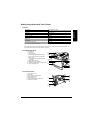
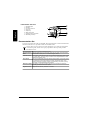
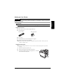
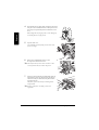
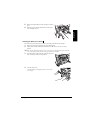
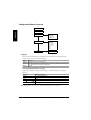
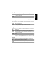
English
magicolor 2200
DeskLaser
Installation Guide
®
1800621-001E
i
Thank You
Thank you for purchasing a magicolor 2200 DeskLaser. You have made an excellent choice. Your
magicolor 2200 DeskLaser is specially designed for optimal performance in Windows and TCP/IP
networking environments.
English
Trademarks
The following are registered trademarks of MINOLTA-QMS, Inc.: QMS, the MINOLTA-QMS logo, and
magicolor.
Minolta is a trademark of Minolta Co., Ltd. Other product names mentioned in this guide may also be
trademarks or registered trademarks of their respective owners.
Proprietary Statement
The digitally encoded software included with your printer is Copyrighted © 2002 by MINOLTA-QMS, Inc. All
Rights Reserved. This software may not be reproduced, modified, displayed, transferred, or copied in any
form or in any manner or on any media, in whole or in part, without the express written permission of
MINOLTA-QMS, Inc.
Copyright Notice
This manual is Copyrighted © 2002 by MINOLTA-QMS, Inc., One Magnum Pass, Mobile, AL 36618. All
Rights Reserved. This document may not be copied, in whole or part, nor transferred to any other media or
language, without written permission of MINOLTA-QMS, Inc.
Manual Notice
MINOLTA-QMS, Inc. reserves the right to make changes to this manual and to the equipment described
herein without notice. Considerable effort has been made to ensure that this manual is free of inaccuracies
and omissions. However, MINOLTA-QMS, Inc. makes no warranty of any kind including, but not limited to,
any implied warranties of merchantability and fitness for a particular purpose with regard to this manual.
MINOLTA-QMS, Inc. assumes no responsibility for, or liability for, errors contained in this manual or for
incidental, special, or consequential damages arising out of the furnishing of this manual, or the use of this
manual in operating the equipment, or in connection with the performance of the equipment when so
operated.
Registering the Printer
Mail—Fill out and send in the registration card enclosed in your shipment.
Internet—Go to www.onlineregister.com/minolta-qms/ and follow the instructions given there.
CD-ROM—Follow the instructions on the CD-ROM.
ii
English
Contents
Getting Acquainted with Your Printer .......................................................................................1
Features 1
Front/Right Side View 1
Front Internal View 1
Left Side/Rear Side View 2
Documentation Set ........................................................................................................................2
Setting up Your Printer ................................................................................................................3
Shipment Contents 3
Unpacking the Printer 3
Installing the Waste Toner Pack 5
Installing the Fuser Oil Roller 6
Removing the Tape from the Transfer Roller 7
Loading Media 8
Loading the Multipurpose Tray 10
Installing Accessories 11
Plugging in/Turning on the Printer ...........................................................................................12
About the Control Panel .............................................................................................................12
Control Panel Indicators 13
Control Panel Keys 13
Configuration Menu Overview .................................................................................................14
Language 14
Sample Page 15
Engine 15
Network 16
Service 19
Connecting the Printer ...............................................................................................................19
Installing Printer Drivers and Software ...................................................................................20
Plug and Play Printer Driver Installation 20
Manually Installing the Printer Driver/Monitor 20
Selecting the Crown Port 21
Troubleshooting ..........................................................................................................................21
Accessories and Consumables ....................................................................................................23
Accessories 23
Consumables 23
i
Regulatory Compliance ..............................................................................................................24
FCC Compliance Statement 25
Canadian Users Notice 25
Laser Safety 25
International Notices 26
English
Warranty Considerations ...........................................................................................................26
Consumables and Your Warranty 26
Manufacturer’s Declaration of Conformity—Europe 220 Volt ..............................................27
Manufacturer’s Declaration of Conformity—Latin America 110 Volt .................................28
Manufacturer’s Declaration of Conformity—Latin America 220 Volt .................................29
ii
Contents
Getting Acquainted with Your Printer
Print Speed
5/20* pages per minute
SDRAM
32 MB
Resolution
1200 x 600 dpi
500-sheet Letter/A4/Legal (Upper Media Tray)
Standard
Multipurpose Tray
Standard
Lower Feeder Unit
Optional
Duplex Unit
Optional
5-bin Mailbox
Optional
64 MB Memory Expansion
Optional
English
Features
*5 = color; 20 = monochrome black
The following drawings illustrate the parts of your printer referred to throughout this guide, so
please take some time to become familiar with them.
Front/Right Side View
1—Output tray
2—Top cover
3—Top cover latch
4—Control panel and message window
5—Front cover latch (one on each side)
6—Front cover
7—Upper media tray (tray also known as
a cassette)
8—Right-side cover latch
9—Multipurpose tray (closed)
10—Pull-out carrying bars (one on each side)
11—Upper feed path cover
11
Front Internal View
1—Toner ejection lever
2—Toner slot
3—Toner carousel release button
4—Toner rotation knob
5—Waste toner pack
6—Transfer belt unit right release lever
7—OPC drum cartridge
Getting Acquainted with Your Printer
1
Left Side/Rear Side View
English
1—Ventilation grille
2—Interface
3—AC power connector
4—Top cover
5—Output tray
6—Main power switch
7—Hand grips for moving printer
8—Media tray (left side)
Documentation Set
Your magicolor 2200 comes with one CD-ROM. All the documentation is on this CD-ROM unless
otherwise noted below. It is provided in Adobe Acrobat PDF format.
You may discover movie camera icons in the manuals. If you’re using the Acrobat PDF
version of this guide, click the icon to play a QuickTime video clip of the procedure
described in the text.
Quick Setup Guide
Use this sheet when unpacking the printer.
Service & Support
Guide
This lists global sources of service and support for your printer. Further information
about MINOLTA-QMS printers is available through the Internet.
Installation Guide
You’re looking at this document right now. This assists in setting up the printer, installing a printer driver, and connecting to a network. It also briefly describes the control
panel and configuration menu.
User’s Guide
The User’s Guide guides you through the day-to-day operation of your printer, including information on printing files, refilling print media, and replacing toner. It also
includes information on handling, cleaning, and maintaining your printer; improving
print quality; and troubleshooting printer problems.
Maintenance Guide This guide is a handy item to keep at the printer for quick reference information
regarding operation and care of the printer.
Registration Card
2
Registration and warranty information is included.
Documentation Set
Setting up Your Printer
WARNING!
English
The printer weighs 87.1 lbs (39.5 kg) without consumables. To avoid injury, at least two people must
lift and move the printer.
Attention
Do not plug in the printer’s power cord before completing all installation steps.
Shipment Contents
Printer with a 500-sheet letter/A4/legal media tray
Consumables kit
Fuser oil roller
Waste toner pack
Power cord
Documentation (see “Documentation Set” on page 2)
Utilities and Documentation CD-ROM
Interface cables aren’t included in the shipment. If you need cables, contact your local
vendor or computer store.
Unpacking the Printer
Save the packing materials in case you ever have to relocate your printer or for future
storage.
1
2
3
Remove the protective plastic cover.
Remove the tape from the outside of the printer.
Take the tape off of the pull-out carrying bars and slide
them outward from the printer.
Setting up Your Printer
3
4
With another person’s help, lift the printer from the carton,
and place it in its intended location. A third person’s assistance may be required if the printer is lifted above waist
level.
English
When lifting and carrying the printer, use the hand grips
and the pull-out carrying bars .
5
Open the front cover.
Use both hands to avoid putting uneven strain on the
front cover hinges.
6
Remove the cardboard/foam spacers and
the tape from the laser lens cover.
The transfer belt left release lever will move to the 4
o’clock position when you remove the spacers.
7
Pressing on the transfer belt unit front handle with one
hand, take the yellow tag attached to the transfer belt
unit fixture with your other hand, and pull the fixture
straight toward you.
This fixture protects the transfer belt during initial
transportation.
Dispose of the fixture according to your local
regulations.
4
Setting up Your Printer
Remove the tape holding the toner cartridge carousel in
place.
9
Remove the piece of foam attached to the front of the
toner cartridge carousel.
English
8
Installing the Waste Toner Pack
The waste toner pack collects the excess toner remaining on the OPC drum cartridge.
1
2
Remove the waste toner pack from its plastic shipping bag.
Make sure the transfer belt unit left release lever is still set to its correct (2 o’clock)
position.
If the transfer belt unit left release lever is at its top (12 o’clock) position or the laser lens
cover is not firmly seated, the waste toner pack cannot be installed.
3
Press the bottom of the waste toner pack into the printer
first, then the top, until it is firmly seated.
2
1
4
Close the front cover.
Use both hands to avoid putting uneven strain on the
cover hinges.
Setting up Your Printer
5
Installing the Fuser Oil Roller
Push the top cover latch and open the top of the
printer .
2
Remove the fuser oil roller from its box.
English
1
Attention
Lift and hold the fuser oil roller only by the handle. Do not allow the roller surface to
contact the table or get dirty. This could lower image quality.
6
3
Rotate the two small levers to the unlocked position.
4
Remove the tape from the media exit area.
5
Insert the fuser oil roller guides into the guide rails,
then carefully lower the roller.
Setting up Your Printer
6
With the top of the printer open, rotate the two fuser oil
roller levers to the locked position.
If the fuser oil roller release levers are not correctly set,
English
the top cover cannot be closed.
7
Close the top cover gently to avoid jarring the fuser oil
roller.
Removing the Tape from the Transfer Roller
1
Press the right cover release button and open the right
cover .
2
Remove the tape from the transfer roller unit.
Setting up Your Printer
7
English
3
Make sure the transfer roller unit handles remain in the
down position.
4
Close the right cover.
Loading Media
Loading the Media Tray
8
1
2
Slide out the media tray.
3
Push the media pressure plate down to lock it
in position.
Remove the tape and the packing material from the
media pressure plate.
Setting up Your Printer
4
Adjust the media guides to fit the size paper you’re loading.
English
Squeeze the retainers, move the guides to the appropriate location (media sizes are listed on
the tray), and release the retainers.
Attention
The media should fit easily between the guides. Improperly adjusted guides may cause
poor print quality, media jams, or printer damage.
5
Load the media face-up, short edge toward the right of
the tray.
Often, an arrow on the media package label
indicates the printing-side of the media.
A fill limit mark is provided on the inside of the tray. The
media tray holds 500 sheets of 20 lb bond (75 g/m²)
paper.
Make sure that the paper fits easily between the guides
and the paper corners are under the left and right
media-separating tabs and are not bent.
For further information about loading and using media,
refer to chapter 2, “Using Media,” in the User’s Guide.
Setting up Your Printer
9
6
Slide the media tray all the way
in.
English
If you have removed the tray from
the printer, slightly tilt up the
front of the tray to insert it into
the guide rails to slide it back in.
1
Open the multipurpose tray.
2
Open the media support.
3
Load the media face down, short
edge toward the printer.
Often, an arrow on the media
package label indicates the
face-up side of the media.
10
FA
C
DO E
WN
Loading the Multipurpose Tray
Setting up Your Printer
English
A fill limit mark is provided on
the inside of the media guides on
the multipurpose tray. The multipurpose tray holds 150 sheets of
20 lb bond (75 g/m²) paper.
Attention
Load only one type or size of media per tray at a time.
4
Adjust the media guides to fit the
size media you’re loading.
LTR
LG .
EXE. L.
A5
B5
A4
Attention
Always adjust the media guides after inserting the media. A guide that is not properly
adjusted can cause poor print quality, media jams, or printer damage.
5
Specify the media size in the multipurpose tray in the printer driver.
For further information about loading and using media, refer to chapter 2, “Using Media,”
in the User’s Guide.
Installing Accessories
If you purchased any printer accessories, then install them now. If installation instructions are
included with the accessory, follow them. If not, instructions are included in the User’s Guide.
A complete list is in “Accessories and Consumables” on page 23. Refer to www.minolta-qms.com
or www.q-shop.com for part numbers and pricing.
Setting up Your Printer
11
Plugging in/Turning on the Printer
1 Make sure the printer is turned off.
2 Plug the printer power cord into the printer and
English
into the dedicated, grounded, surge-protected
electrical outlet.
WARNING!
Do not overload the outlet. For products installed outside North America, do not connect the
groundwire to gas or water pipes or grounding for telephones.
3
Turn on the printer.
After a brief warmup, your printer displays “IDLE” on
the message window. If “IDLE” is not displayed in the
message window after the power switch is turned on, the
setup operation is not proceeding correctly or the
printer may be malfunctioning. Recheck the setup.
The printer automatically switches to power-saving
mode after 60 minutes of inactivity. In the Engine/
Energy Saver menu, you can change the number of
minutes before the printer switches to power-saving mode.
In compliance with UL guidelines, “The appliance inlet is considered to be the main
disconnect device.”
About the Control Panel
The control panel, located on the front of the printer, allows you to direct the printer’s operation. In
addition, it displays the current status of the printer, including any condition that needs your
attention. The control panel consists of the following parts:
Three indicators (LEDs) to provide printer status information.
A message window to display status and configuration information.
Seven keys to allow you to control the printer configuration through access to frequently used
printer functions.
MESSAGE
WINDOW
12
Plugging in/Turning on the Printer
Control Panel Indicators
Indicator
Off
On
The printer is not receiving data.
The printer is receiving data from one or
more of its interfaces.
No problem.
The printer requires operator attention (usually accompanied by a status message in
the message window).
Control Panel Keys
Key
MP SIZE
Function
PressOn
line
First?
N/A
This key has no function on the magicolor 2200 DeskLaser but is used to set
the mutipurpose tray media size on magicolor 2200 Crown printers. Media
sizes are controlled through the printer driver on magicolor 2200 DeskLaser
printers.
Accesses the configuration menu. When you’re changing the printer configura- Yes
tion, press this key to cancel a change (before pressing the Select key), to
return to the previous selection or option for the current menu and to return to
the previous choice when changing character information.
The Select key selects a menu or a displayed menu option.
Yes
Use this key to advance to the next selection for the current menu or to
advance to the next choice when changing character information.
The Online key switches the printer between online and offline status. Press N/A
the key once to take the printer off line when it is on line, and press the key
once to return the printer to on line when it is off line.
The Cancel key allows you to cancel a print job.
No
Previous/Next navigation keys allow you go backward or forward through the Yes
menu choices.
About the Control Panel
13
English
The printer is off line and not ready to accept The printer is on line and ready to accept
data.
data.
Configuration Menu Overview
Language
English
Sample Page
Engine
Network
Service
Error recovery
Energy saver
Print density
Chain inputbins
Chain outputbins
IP address
HW address
Subnet mask
Conn. timeout
Ethernet speed
Default router
NMS1
NMS2
NMS3
Page count
Clear care
Language
Status and error messages as well as configuration menus and options can be displayed in the
message window in one of the available languages.
Menu
Language
Purpose
Change the message window language.
Choices
Chinese Simplified, Chinese Traditional, Czech, Danish, Dutch, English, French, German, Italian, Japanese, Korean, Portuguese, and Spanish.
Default
English
Selecting a Message Window Language
If you want to change the message window language, use the following quick control panel
sequence:
Press Key
(Until) Display Reads
Online
IDLE (and online LED is off)
Menu
LANGUAGE
Select
*ENGLISH
Next (
Select
14
) / Previous (
)
Press the Next and/or Previous key until the language required is displayed
<LANGUAGE> IS SELECTED
The printer must be restarted for changes to the Language menu to take effect.
Configuration Menu Overview
Sample Page
This menu item initiates the printing of a sample page that can be used to check print quality.
Sample Page
Purpose
Prints a sample page.
Choices
Yes—Prints a sample page.
No—Doesn’t print a sample page.
Default
Yes
English
Menu
Engine
The following menus allow you to configure the hardware control settings of your printer.
Error Recovery
When the Error Recovery feature is On, the printer will automatically reprint pages that are halted
due to media jams or other errors.
Menu
Engine/Error Recovery
Purpose
Enables or disables error recovery.
Choices
On—Reprints a print job from the page on which the jam or error occurred.
Off—Don’t reprint a print job when a jam or error occurs.
Default
On
Energy Saver
From this menu item you can set the time interval that the printer must remain inactive before it
will switch to a state of reduced power consumption.
Menu
Engine/Energy Saver
Purpose
Sets the length of inactivity before the printer changes to a low-power state (the engine
remains on, but the fuser turns off).
Choices
15 minutes, 30 minutes, 1 hour, 2 hours, 3 hours—Idle time before activation of low-power
state.
Off—Use normal power all the time.
Default
30 minutes
Notes
After the chosen time expires (for example, 30 minutes), the printer enters a low-power mode.
The printer remains in low-power mode until a print job is received or until the printer is manually switched from offline to online. After receiving a signal to print or to go on line, the printer
warms up and returns to normal power.
Print Density
This menu item allows you to adjust the amount of toner applied during the printing process.
Menu
Engine/Print Density [Yellow, Magenta, Cyan, and Black]
Purpose
Adjusts toner (color) density.
Choices
-1.6%, -0.8%, 0%, +0.8%, +1.6% (lowest to highest density)
Default
0%
Configuration Menu Overview
15
Chain Inputbins
English
This menu item is available only if an optional media cassette is installed.
Menu
Engine/Chain Inputbins
Purpose
Allows you to “chain” cassettes (inputbins) so that when the first cassette empties, the printer
automatically draws media from the other cassette.
Choices
On—Switch to the next cassette with the same size and type of media when the default cassette is empty.
Off—Don’t switch cassettes; use only the default cassette.
Default
On
Chain Outputbins
This menu item is available only if an optional 5-bin mailbox is installed.
Menu
Engine/Chain Outputbins
Purpose
Allows you to “chain” mailbox bins (outputbins) so that when the first bin fills, the printer automatically sends output to the next available bin.
Choices
On—Switch to the next available bin when the default bin is full.
Off—Don’t switch bins; use only the default outputbin.
Default
Off
Network
The following menu items allow you to configure your printer for connection to your network.
IP (Internet) Address
The IP Address menu allows you to set the printer’s network (Internet Protocol) address. The
address is in the format xxx.xxx.xxx.xxx.
Menu
Network/Internet address
Choices
Each xxx.xxx.xxx.xxx triplet can have a value of 001–254.
Default
161.033.128.024
Notes
This address must be set, and it must be unique.
Once you save your changes to this menu, the printer automatically reboots.
The address must consist only of numbers and periods. Selecting a letter or another symbol
results in an error message.
All xxx values must be three digits (for example, 1 is entered as 001, and 10 is entered as 010).
HW (Hardware) Address
The HW Address menu allows you to view the printer’s factory-default Ethernet hardware
address.
16
Menu
Network/HW address
Choices
None (read-only)
Default
The printer’s hardware address in the form HW:080086 xxxxxx
Configuration Menu Overview
Subnet Mask
Menu
Network/Subnet mask
Choices
Each xxx.xxx.xxx.xxx triplet can have a value of 001–254.
Default
000.000.000.000
Notes
If subnets are not used with your network, the subnet mask should remain 000.000.000.000.
(Check with your network administrator.) This allows the interface to provide automatic sensing
of gateways. If you identify a subnet mask, this automatic sensing is disabled.
Once you save your changes to this menu, the printer automatically reboots.
The address must consist only of numbers and periods. Selecting a letter or another symbol
results in an error message.
All xxx values must be three digits (for example, 1 is entered as 001, and 10 is entered as 010).
Connection Timeout
This setting determines the amount of time that the network connection can remain inactive before
it is closed.
Menu
Network/Conn. Timeout
Choices
0–999 (seconds)
Default
0
Notes
A new network connection is established every time a print job is sent to the printer.
Ethernet Speed
The Ethernet Speed menu allows you to select the Ethernet network speed.
Menu
Network/Ethernet Speed
Choices
Autodetect
10MBit–10 Mbit/Sec Half Duplex
100MBit–100 Mbit/Sec Half Duplex
Default
Autodetect
Effectivity
Immediately
Default Router
The Default Router menu allows you to set the Internet address of a router. The address is in the
format xxx.xxx.xxx.xxx.
Menu
Network/Default Router
Choices
Each xxx.xxx.xxx.xxx triplet can have a value of 001–254.
Default
000.000.000.000
Notes
If gateways are not used with your network, the router address should remain
000.000.000.000. (Check with your network administrator.)
Once you save your changes to this menu, the printer automatically reboots.
The address must consist only of numbers and periods. Selecting a letter or another symbol
results in an error message.
All xxx values must be three digits (for example, 1 is entered as 001, and 10 is entered as 010).
Configuration Menu Overview
17
English
The Subnet Mask menu allows you to set the printer’s subnet mask. The address is in the format
xxx.xxx.xxx.xxx.
NMS1–NMS3
SNMP (Simple Network Management Protocol) is a standard protocol used to monitor devices and
the networks to which they attach.
English
The NMS1, NMS2, NMS3 menus allow you to identify and configure up to three
Network Management Stations (NMSs). You must provide the following information about each
NMS that you want to be able to access the printer: address, community name, and access.
NMSx Address
The NMS Address option allows you to set the IP (internet protocol) network address for the NMS
so the printer can communicate with the network. Traps, if enabled, are sent to this address. The
address has the form xxx.xxx.xxx.xxx.
Menu
Network/NMSx/NMSx Address
Choices
Each triplet can have a value of 000–255
Default
000.000.000.000
Notes
000.000.000.000 is a wildcard address that allows any host to connect to the printer using the
defined community name.
The address must consist only of numbers and periods. Selecting a letter or another symbol
results in an error message.
The printer must be rebooted before changes to this setting will go into effect.
Any xxx value between 10 and 99 must begin with 0 (for example, 10 is entered as 010 and 99
is entered as 099).
Any xxx value between 1 and 9 must begin with 00 (for example, 1 is entered as 001 and 9 is
entered as 009).
NMSx Community Name
A community is a group of SNMP agents managed by an NMS, and a community name is
associated with a specific NMS address. For the NMS to gain access to the device, the correct
community name (up to 15 characters in length) must be supplied when connecting.
Menu
Network/NMSx/NMSx Community
Choices
Up to 15 characters
Default
Public
Notes
The printer must be rebooted before changes to this setting will go into effect.
NMSx Access
The NMS Access option provides security for the SNMP by configuring the privileges associated
with each NMS.
18
Menu
Network/NMSx/NMSx Access
Choices
None—The NMS isn’t configured. Other configured NMS’s can still access the printer via
SNMP.
Read—The NMS can read all SNMP variables.
Read-Trap—The NMS can read all SNMP variables and receive traps.
Trap—Traps are sent to the NMS (if defined) when printer errors occur.
Write—The NMS can read all SNMP variables as well as set the ones so defined.
Write-Trap—The NMS can read all SNMP variables, set the ones so defined, and receive
SNMP traps on printer errors.
Default
Read
Note
The printer must be rebooted before changes to this setting will go into effect.
Configuration Menu Overview
The 3 NMS’s are recognized by the printer in sequential order, with NMS1 first and NMS3 last.
When a connection is made, the printer looks for a matching IP address assigned to the NMS’s,
and stops looking once a match is found. Since the IP address setting of 000.000.000.000 is
treated as a wildcard, if NMS1 has this setting, then the other 2 NMS’s have the access assigned
to NMS1. If a match isn’t made, then the printer looks for a match with NMS2, and if necessary,
NMS3.
English
Service
Service menu items are used to clear service messages and to view the number of faces printed.
Page Count
This menu item allows you to view the number of pages that have been printed.
Menu
Service/Page Count
Choices
None (read-only)
Default
0
Clear Care
Use this menu item to clear service messages from the control panel message window.
Menu
Service/Clear Care
Choices
Yes, No
Default
No
Notes
Service messages will be erased from the control panel message window after you select Yes
in this menu, and then place the printer back on line.
Connecting the Printer
1 The interface panel is located on the left back of the printer.
Parallel connection
Using a Centronics IEEE 1284 bidirectional parallel
cable, connect the parallel port on the printer to the parallel port on your computer.
Ethernet connection
Parallel port
Ethernet port
Using a twisted-pair (RJ45) Ethernet cable, connect the
Ethernet port on the printer to a 10BaseT/100BaseTX
network connection.
2
If necessary, in the Network/IP Address menu, enter the
printer’s Internet address.
3
If necessary, in the Network/Subnet Mask menu, enter the
printer’s subnet mask.
4
If necessary, in the Network/Default Router menu, enter the Internet address of the default
router.
Connecting the Printer
19
Installing Printer Drivers and Software
The printer driver and additional software found on the Utilities and Documentation CD-ROM can
be installed on PCs using any of the following operating systems:
— Windows XP
English
— Windows Me
— Windows 2000
— Windows NT4
— Windows 98
— Windows 95(B)
Plug and Play Printer Driver Installation
1
2
Ethernet connections don’t support Plug and Play technology. If you’re using an Ethernet
network connection, skip to the next section.
Under certain PC configurations, the Utilities and Documentation CD-ROM automatically
launches its own installation utility. If this should occur during the Plug and Play procedure,
cancel the Plug and Play installation and install the driver using the CD-ROM installer for easy
access to color management and online documentation.
With your PC turned off, turn on the printer (the power switch is on the left side of the
printer), and then turn on your PC. A Found New Hardware message appears. Follow
the directions for your operating system:
Windows Me/98/95
XP/2000/NT4
Insert the Utilities and Documentation
CD-ROM.
Select
Search (Windows 2000/NT4)
or
Install.....Specific Location
(Windows XP)
When the Other Locations window
appears, choose
Select Other Location.
Insert the Utilities and Documentation
CD-ROM.
Select
Browse
Select
CD-ROM Drives
De-select all other choices.
Locate the Driver directory on the CD-ROM,
and then choose OK.
Choose
Next
Follow the instructions on the screen to complete the installation of the printer driver. When
the installation is complete, the Windows desktop appears. Remove the CD-ROM from the
PC, and store it in a safe place.
During software installation you can view online help by choosing the Help button.
Manually Installing the Printer Driver/Monitor
1
2
20
If you installed the printer driver using Plug and Play technology, skip this section.
Insert the Utilities and Documentation CD-ROM in the CD-ROM drive on your computer.
When the installation application window appears, select Install Printer Utility
and Driver, and then follow the on-screen instructions.
Installing Printer Drivers and Software
Selecting the Crown Port
1
2
3
From the Start menu, choose Settings.
4
5
Choose Properties.
6
From the Print To The Following Port list, choose
the Crown port that was added during the Crown
Print Monitor installation.
7
8
Choose OK to close the Printer Properties window.
English
The Crown Print Monitor for Windows XP/2000/NT4/Me/98/95 transports print jobs to a print
device using the TCP/IP protocol and provides status information to the host. If you installed the
Crown Print Monitor, follow the instructions in this section to assign the new Crown port that was
created.
Choose Printers.
In the Printers window click the right mouse button
on the magicolor 2200 DeskLaser printer to display
the printer’s menu.
Choose the Details tab (Windows Me/98/95) or
Ports tab (Windows XP/2000/NT4).
Close the Printers window.
For additional information about the Crown Print Monitor, see the Crown Print Monitor
Administrator’s Guide. For information about the print monitor that comes with Microsoft
Windows XP/2000, see your Windows documentation.
Troubleshooting
Although the magicolor 2200 is designed to be highly reliable, you may occasionally experience a
problem. The following helps you to identify the cause of the possible installation problems and
suggests some solutions related to installation. For additional troubleshooting information, refer to
“Troubleshooting” in the User’s Guide.
Troubleshooting
21
Symptom
Cause
English
Printer power The power cord is not
is not on.
correctly plugged into the outlet.
Solution
Turn the power switch off (O) position, then remove the
power cord from the outlet and plug it back in.
The power switch is not correctly
turned on.
Set the power switch to the off (O) position, then set it
back to the on (I) position.
Something is wrong with the outlet
you are using for the printer.
Plug another electrical appliance into the outlet and see
whether it operates properly.
The printer is connected to an outlet Check the voltage and frequency of the outlet. Use a
with a voltage or frequency that does power source with the following specifications:
not match the printer specifications. —Power
Japan: 100 VAC 50–60 Hz 12 amps
North America: 120 VAC 50–60 Hz 8 amps
Europe: 220-240 VAC 50–60 Hz 6 amps
Latin America: 120 VAC 50–60 Hz 8 amps
220-240 VAC 50–60 Hz 6 amps
—Voltage fluctuation
Japan: 100 VAC ±10%
North America: 120 VAC ±10%
Europe: 220-240 VAC ±10%
Latin America: 120 VAC ±10%
220-240 VAC ±10%
—Frequency fluctuation rate within 50/60 ±3 Hz
No lights or
messages
appear on
the control
panel.
There is no power supplied to the
AC outlet.
Make sure there is power supplied to the AC outlet.
The power cord is not plugged in
securely into both the power outlet
and the printer.
Make sure the power cord in plugged in securely both at
the power outlet and the printer.
The printer power switch is not in the Turn the printer power switch to the On (I) position.
On (I) position.
The line voltage from the power out- Make sure the line voltage matches the printer’s power
let doesn’t match the printer’s power requirements.
requirements.
You can’t
print a sample page.
Is the printer off line before you try to Turn the printer off line and then proceed to the Sample
enter the Sample Page menu?
Page menu selection.
The tray does not have media.
Check that the media trays are loaded with media, in
place and secure.
The printer’s covers aren’t closed
securely.
Make sure the front and top covers are closed securely.
Close all covers gently to avoid jarring the printer. Make
sure the waste toner pack in installed correctly.
There is a media jam.
Remove the media jam.
The printer is The printer is not on line.
not receiving
data. (The
Data indicator doesn’t
blink after a
file is sent.)
22
Put the printer on line and check if the message window
displays IDLE.
Top cover
does not
close.
The fuser oil roller release lever is
not set in the correct position.
Open the top cover and turn the fuser oil roller release
lever (two locations) to the locked position, then close
the cover gently to avoid jarring the printer.
Front cover
does not
close.
The transfer belt right release lever
is not set in the correct position.
Turn the right release lever clockwise to the 2 o’clock
position, then close the front cover.
The waste toner is not set correctly. Remove the waste toner, then reinstall it correctly.
Troubleshooting
Symptom
Cause
Waste toner
pack cannot
be installed.
The transfer belt left release lever is Turn the left release lever clockwise to the 2 o’clock
not set correctly.
position, then install the waste toner.
Solution
The toner cartridge carousel dial is
Toner
turned clockwise.
cartridge
carousel will
not turn.
Turn the carousel dial counterclockwise.
The toner cartridge
Toner
carousel release button was not
cartridge
carousel dial pressed.
will not turn.
Press and release the carousel release button, the turn
the carousel dial counterclockwise.
A toner cartridge was not inserted in
Toner
that slot.
cartridge
carousel slot
is empty.
Press the toner release button and turn the carousel
dial until you reach the empty slot. Install the missing
toner cartridge. You do not have to load the toner in a
set sequence.
The fuser release lever is not set in
Fuser oil
roller cannot the correct position.
be installed.
Turn the left release lever clockwise to the 12 o’clock
position, then install the fuser oil roller.
OPC drum
unit cannot
be installed.
The transfer belt left release lever is Turn the left release lever counterclockwise to the
not set to the OPC drum installation 12 o’clock position, then install the OPC drum unit.
position.
Pages come Media improperly aligned in tray or
out skewed. bad media.
Check media in trays.
The waste toner pack isn’t properly
CHECK
installed.
WASTE
TONER
message
appears in
the message
window.
Make sure the waste toner pack sits snugly against the
printer.
A consumable item, such as paper
or toner, has run out.
Handle the message according to the message display.
Error message is displayed.
A unit or tray is not correctly
installed.
The media is jammed.
A problem occurred inside the
printer.
Accessories and Consumables
Refer to www.minolta-qms.com or www.q-shop.com for part numbers and pricing.
Accessories
Description
Remark(s)
5-bin Mailbox
Three models: For 100-, 120-, or 220-volt printers.
BuzzBox
Via parallel connection for 100, 120, and 220 volts.
Dual In-Line Memory Module (DIMM)
Additional memory must be a 64 MB, PC-100 Compliant SDRAM DIMM.
Duplex Unit
Automatic duplexing.
Lower Feeder Unit
Media tray included.
Accessories and Consumables
23
English
The laser lens cover is not installed, Reinstall the laser lens cover.
or was not installed correctly.
English
Description
Remark(s)
Media Tray, 500 Sheet
Purchasing extra trays may be convenient when
changing media formats and/or media qualities vary.
Printer Stand/Cabinet
Various models are available.
Crown Conversion Kit
Converts a magicolor 2200 DeskLaser to a
magicolor 2200 Crown printer model.
Consumables
Description
Remark(s)
Fuser oil roller
FUSER OIL LOW, FUSER OIL EMPTY, or REPLACE OIL ROLLER displays in the message window (after up to 21,000 single-sided continuous
monochrome or 7,500 continuous color pages, or 7,000 intermittent
[one-page jobs] monochrome or 5,000 intermittent [one-page jobs] color
pages). Heavy coverage, intermittent printing, and different media types
can use oil at an accelerated rate, reducing fuser and oil roller life.
Fuser unit/transfer roller kit
REPLACE FUSER displays in the message window (after 100,000 single-sided pages maximum at an equal mix of black and 4-color pages, all
with 5% coverage of each color; however, fuser unit life is media dependent).
Toner cartridge: Cyan,
Magenta, Yellow,
and Black
<COLOR> TONER EMPTY displays in the message window (after approximately 6,000 single-sided pages per cartridge—black, yellow, magenta,
cyan at 5% coverage of each color).
OPC drum kit
REPLACE DRUM, CHECK WASTE TONER, WASTE TONER NEAR FULL,
(OPC drum cartridge, laser lens or REPLACE WASTE TONER displays in the message window (up to
30,000 continuous monochrome* or 7,500 continuous four-color pages, or
cover, and waste toner pack)
10,000 intermittent monochrome or 5,000 intermittent color pages). Other
factors also affect cartridge life.
Transfer belt
REPLACE TRANSFER BELT displays in the message window (after
107,000 pages continuous monochrome or 33,000 continuous color pages,
or 44,000 intermittent monochrome or 23,000 intermittent color pages).
Consumable life is expressed in simplex letter/A4 pages. A duplex page is equivalent to two
simplex pages.
Regulatory Compliance
24
CE Marking and
Immunity
Requirements
(EU)
International (EU)
EN 55024
EN 50081-1
EN 61000-3-2
EN 61000-3-3
IEC 61000-4-2
IEC 61000-4-3
IEC 61000-4-4
IEC 61000-4-5
IEC 61000-4-6
IEC 61000-4-8
IEC 61000-4-11
Immunity Characteristics
Generic Emission Standard
Harmonic Current Emissions
Voltage Fluctuations and Flicker
ESD
Radiated Susceptibility
Fast Transients
Surge Immunity
Immunity to Conducted Disturbance
Magnetic Field Immunity
Voltage Dips and Variations
cTick Mark
ACA (Australia)
AS/NZS 4251
AS/NZS 3458
Generic Emissions Standard
ITE
Regulatory Compliance
FCC (USA)
Title 47 CFR Ch. I, Part 15
Industry Canada (Canada)
ICES-003 Issue 3
International (EU)
EN 55022
VCCI (Japan)
VCCI V-1/98.04
Class B Digital Device
(Class A Digital Device with Token-Ring or LocalTalk
interface installed)
Class B Digital Device
(Class A Digital Device with Token-Ring or LocalTalk
interface installed)
Class B ITE
Class A Digital Device with Token-Ring interface
installed)
Class B ITE
(Class A Digital Device with LocalTalk interface
installed)
Energy Saver
ENERGY STAR (USA)
ENERGY STAR Compliant
Product Safety
UL (USA)|
cUL (Canada)
UL 1950, Third Edition
CAN/CSA C22.2 No. 950-93
TUV/GS and CB
Scheme
International (EU)
EN 60950 and IEC 60950
Laser Safety
CDRH (USA)
Title 21 CFR Ch. I, Subchapter J
International (EU)
EN 60825-1
FCC Compliance Statement
WARNING!
Any modifications or changes to this product not expressly approved in writing by the manufacturer
responsible for compliance to Federal Regulations could void the user's authority to operate this
product within the Laws and Regulations of the Federal Communications Commission.
Class B
This equipment has been tested and found to comply with the limits for a Class B digital device,
pursuant to Part 15 of the FCC Rules. These limits are designed to provide reasonable protection
against harmful interference in a residential installation. This equipment generates, uses, and can
radiate radio frequency energy and, if not installed and used in accordance with the instruction,
may cause harmful interference to radio communications. However, there is not guarantee that
interference will not occur in a particular installation. If this equipment does cause harmful
interference to radio or television reception, which can be determined by turning the equipment off
and on, the user is encouraged to try to correct the interference by one or more of the following
measures:
Reorient or relocate the receiving antenna
Increase the separation between the equipment and receiver
Connect the equipment into an outlet on a circuit different from that to which the receiver is
connected
Consult the dealer or an experienced radio/TV technician for help
A shielded cable is required to comply with the limits for a Class B digital device, pursuant to
Part 15 of the FCC Rules.
Regulatory Compliance
25
English
Electromagnetic
Emissions (EMI)
Class A
This is a class B device, but with an optional Token-Ring or LocalTalk interface installed, it
changes to a Class A device.
English
This equipment has been tested and found to comply with the limits for a Class A digital device,
pursuant to Part 15 of the FCC Rules. These limits are designed to provide reasonable protection
against harmful interference in a commercial environment. This equipment generates, uses, and
can radiate radio frequency energy, and if not installed and used in accordance with the instruction
manual, may cause harmful interference to radio communications. Operation of this equipment in
a residential area is likely to cause harmful interference, in which case the user will be required to
correct the interference at his/her own expense.
Canadian Users Notice
This Class B digital apparatus complies with Canadian ICES-003.
Cet appareil numérique de la classe B est conforme à la norme NMB-003 du Canada.
Laser Safety
This printer is certified as a Class 1 laser product under the U.S. Department of Health and Human
Services (DHHS) Radiation Performance Standard according to the Radiation Control for Health
and Safety Act of 1968. This means that the printer does not produce hazardous laser radiation.
Since radiation emitted inside the printer is completely confined within protective housings and
external covers, the laser beam cannot escape from the machine during any phase of user operation.
International Notices
Power Cord
The following power cord requirements are in effect for the 220v magicolor 2200.
2
Minimum
0.75 mm
Minimum
H05 VV - F
The male plug is certified in the country in which the equipment is to be installed, and
the female plug is an IEC 320 connector.
Voltage
Attention Norwegian users: This equipment is designed to operate within an IT power system
where the line-to-line voltage does not exceed 240v.
Lithium Batteries
Attention Swiss users: Lithium batteries need to be disposed of in accordance with Annex 4.1 of
SR814.013.
Warranty Considerations
Various factors can affect a printer’s warranty. Two important ones are consumables
and electrostatic discharge. Read your printer warranty carefully.
26
Warranty Considerations
Don’t return any merchandise to the manufacturer without calling for a return merchandise
authorization (RMA) number. Refer to the Service & Support Guide for the Support telephone
number where you can obtain an RMA number.
Consumables and Your Warranty
Use of consumables not manufactured by MINOLTA-QMS or use of non-supported print media
may cause damage to your printer and void your warranty. If MINOLTA-QMS printer failure or
damage is found to be directly attributable to the use of non- MINOLTA-QMS consumables and/or
accessories, MINOLTA-QMS will not repair the printer free of charge. In this case, standard time
and material charges will be applied to service your printer for that particular failure or damage.
To order consumables and accessories, go to www.q-shop.com or check the Service & Support
Guide for the MINOLTA-QMS office closest to you.
Warranty Considerations
27
English
If you have any questions, refer to www.minolta-qms.com.
Manufacturer’s Declaration of Conformity—Europe 220 Volt
We:
MINOLTA-QMS Europe B.V.
(supplier’s name)
English
Reactorweg 160, 3542 AD Utrecht, The Netherlands
(address)
declare under our sole responsibility that the product
magicolor 2200 DeskLaser
(base product family name)
MC2200GDI-2
(model number located on dataplate)
4120
(print engine model/type number)
to which this declaration relates is in conformity with the following standard(s) or other normative
document(s)
EN 60950:1992+A1+A2+A3+A4+A11, CB Scheme in accordance with
IEC 60950:1991+A1:1992+A2:1993+A3:1995+A4:1996,
CB Certificate No. US-TUVR-0562
EN 60825-1:1994+A11, EN 55022:1998, EN 55024:1998,
EN 61000-3-2:1995+A1:1997+A2:1998, EN 61000-3-3:1995,
IEC 61000-4-2: 1995+A1:1998
IEC 61000-4-3:1995+A1:1998, IEC 61000-4-4:1995, IEC 61000-4-5:1995,
IEC 61000-4-6:1996, IEC 61000-4-8:1993 and IEC 61000-4-11:1994
(title and/or and number and date of issue of the standard(s) or other normative document(s))
(if applicable) following the provisions of 73/23/EEC, 89/336/EEC Directive(s).
Utrecht, The Netherlands—November, 2000
(place and date of issue)
28
Manufacturer’s Declaration of Conformity—Europe 220 Volt
Manufacturer’s Declaration of Conformity—Latin America 110
Volt
We:
MINOLTA-QMS, Inc.
English
(supplier’s name)
One Magnum Pass, Mobile, Alabama, USA, 36618
(address)
declare under our sole responsibility that the product
magicolor 2200 DeskLaser
(base product family name)
MC2200GDI-1
(model number located on dataplate)
4120
(print engine model/type number)
to which this declaration relates is in conformity with the following standard(s) or other normative
document(s)
UL 1950 Third Edition, 1995; cUL CAN/CSA C22.2 No. 950-M95;
FCC Class B Digital Device Title 47 CFR Ch. I., Part 15;
FCC Class A Digital Device Title 47 CFR Ch. I., Part 15 applies for systems configured with
Token-Ring or LocalTalk interface installed;
Industry Canada ICES-003 Issue 3 Class B Digital Device;
Industry Canada ICES-003 Issue 3 Class A Digital Device applies for systems
configured with Token-Ring or LocalTalk interface installed;
EPA ENERGY STAR Office Equipment Program;
CDRH Laser Safety Title 21 CFR Ch. I., Subchapter J;
MSDS Title 29 CFR Ch. XVII, Part 1910.1200.
(title and/or and number and date of issue of the standard(s) or other normative document(s))
(if applicable) following the provisions of N/A Directive(s).
Mobile, Alabama, USA—November, 2000
(place and date of issue)
Manufacturer’s Declaration of Conformity—Latin America 110 Volt
29
Manufacturer’s Declaration of Conformity—Latin America 220
Volt
We:
MINOLTA-QMS, Inc.
English
(supplier’s name)
One Magnum Pass, Mobile, Alabama, USA, 36618
(address)
declare under our sole responsibility that the product
magicolor 2200 DeskLaser
(base product family name)
MC2200GDI-2
(model number located on dataplate)
4120
(print engine model/type number)
to which this declaration relates is in conformity with the following standard(s) or other normative
document(s)
EN 60950:1992+A1+A2+A3+A4+A11, CB Scheme in accordance with
IEC 60950:1991+A1:1992+A2:1993+A3:1995+A4:1996,
CB Certificate No. US-TUVR-0562
EN 60825-1:1994+A11, EN 55022:1998, EN 55024:1998,
EN 61000-3-2:1995+A1:1997+A2:1998, EN 61000-3-3:1995,
IEC 61000-4-2:1995+A1:1998,
IEC 61000-4-3:1995+A1:1998, IEC 61000-4-4:1995, IEC 61000-4-5:1995,
IEC 61000-4-6:1996, IEC 61000-4-8:1993, and IEC 61000-4-11:1994
(title and/or and number and date of issue of the standard(s) or other normative document(s))
(if applicable) following the provisions of 73/23/EEC, 89/336/EEC Directive(s).
Mobile, Alabama, USA—November, 2000
(place and date of issue)
30
Manufacturer’s Declaration of Conformity—Latin America 220 Volt