1
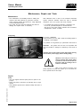
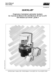
Owner Manual Operating Instructions 2.1A-30004-A02 QuickData® Subject to change without notice Pump 233 with Data Logger 4354a01 Requesting a service page in French, Italian/Spanish language, see page 35 Ordenar manual en español: página 35 Pour la commande de ce manuel en français, voir page 35 Ordinazione della documentazione italiana, vedi pagina 35 810-55293-1 Page 1 of 36 LINCOLN GmbH & Co. KG Postfach 1263 D-69183 Walldorf Tel +49 (6227) 33-0 Fax +49 (6227) 33-259 Owner Manual Operating Instructions 2.1A-30004-A02 Fields of Application of the QUICKDATA Progressive Central Lubrication Pumps Industry - Machines - Commercial Vehicles Building Machinery - Agricultural Machines Pump Type Pump : Reservoir : Control : QUICKDATA 233 2 l -2XL*,2XLFL*, 2XLBO* 4 l -4XLBO* 8 l - 8XLBO* * Filling from the bottom 4l, 8l with lockable reservoir lid (option) Low-level control (option) for all reservoir sizes Integrated control unit with metering device monitoring and data memory QuickData. Subject to change without notice See the respective model designation on the pump type plate e.g. P233-2XL-1K6-24-2A5.10-MDF00 Page 2 of 36 LINCOLN GmbH & Co. KG Postfach 1263 D-69183 Walldorf Tel +49 (6227) 33-0 Fax +49 (6227) 33-259 Owner Manual Operating Instructions 2.1A-30004-A02 Table of Contents Page Fields of application of QUICKDATA central lubrication pumps ................................... ..........2 Safety instructions ........................................................ 4 Pump types ..................................................................... 5 Identification code - pump models ............................. 6 Description of the QUICKDATA pump 233 .................. 8 Functions of the data logger ........................................ 8 Mode of operation of pump 233 .................................. 9 Pump elements with fixed lubricant output .................. 9 Suction phase ........................................................... 9 Delivery phase .......................................................... 9 Check valve .............................................................. 10 Arrangement of the pump elements ..................... 10 Pump elements with adjustable lubricant output ..... 10 Adjustment of the output ........................................ 11 Retrofit adjustment of the max. output ................. 11 Adjustment of small lubricant outputs .................. 11 Pressure relief valve ..................................................... 12 Return line connection ................................................. 13 Printed circuit board with data logger ......................... 13 Membrane key pad ................................................. 15 Page Low-level control ......................................................... 17 Adjustment and operation of the control ................. 18 Display mode ................................................................ 18 Operating mode ............................................................ 19 Programming mode ..................................................... 20 Maintenance, repair and tests ................................... 21 Maintenance .................................................................. 21 Pump filling ................................................................... 21 Repair . .......................................................................... 21 Tests . 22 Test run/To trigger an additional lubrication ........ 22 To check the pressure relief valve ......................... 22 Troubleshooting ........................................................... 23 Technical data .............................................................. 24 Tightening torques ....................................................... 24 Weights .......................................................................... 24 Diagram of electrical connections .............................. 25 Dimensions ................................................................... 26 Lubricants ..................................................................... 32 Further information can be found in the following manuals: - Subject to change without notice - Technical Description for Diagnostic Software QuickData for pump 233 and QLS 333 Technical Description for progressive divider valves models SSV and SSVM for grease and oil Installation instructions Parts Catalog Spare Parts Catalog for pumps 103 and 203 Page 3 of 36 LINCOLN GmbH & Co. KG Postfach 1263 D-69183 Walldorf Tel +49 (6227) 33-0 Fax +49 (6227) 33-259 Owner Manual Operating Instructions 2.1A-30004-A02 Safety Instructions Appropriate Use Use the 233 pump only for dispensing lubricants in centralized lubrication systems. The pump is designed for interval operation. General Safety Instructions LINCOLN - QUICKDATA - centralized lubrication systems - are state of the art; - can be assembled for safe operation Incorrect use may result in bearing damage caused by poor or excessive lubrication. Unauthorized modifications or changes to an installed system are not admissible. Any modification must be subject to prior consultation with the manufacturer of the lubrication system. Regulations for Prevention of Accidents Adhere to the regulations for prevention of accidents which are effective in the country where the system is to be used. Operation, Maintenance and Repair Repairs should only be performed by authorized and instructed personnel familiar with the regulations. LINCOLN - QUICKDATA - central lubrication pumps 233 must be operated only with fitted pressure relief valve. LINCOLN - QUICKDATA - central lubrication pumps 233 must be regularly refilled with clean lubricant. Attention: Before opening the reservoir cover for filling purposes, switch off the power supply. Attention: When filling the reservoir by means of pumps with a large delivery volume do not exceed the max. filling mark. Risk of bursting if the reservoir is overfilled! The manufacturer of the centralized lubrication system will not accept any liability for: - damage caused by insufficient lubricant and irregular pump refilling, - damage caused by the use of used or contaminated lubricants, - damages due to the use of greases which are not or only conditionally pumpable in centralized lubrication systems, - damage caused by unauthorized modification of the system components, - damage caused by the use of unapproved spare parts. Installation Any safety equipment already fitted to the vehicle, device or machine: - should not be modified or made ineffective, - should only be removed for the purpose of fitting the system, - must be replaced afterwards. Keep QUICKDATA centralized lubrication systems away from sources of heat. Adhere to the operating temperature. Use only original LINCOLN spare parts (see Parts Catalog) or parts approved by LINCOLN. Adhere to: - the installation instructions of the manufacturer of construction machinery, vehicles or machines as regards all drilling and welding procedures, - the specified minimum distances between the bore holes and the upper/lower rim of the frame or between two bore holes. Subject to change without notice LINCOLN - QUICKDATA - central lubrication systems operate automatically. However, a regular check (about every two weeks) should be made to ensure that lubricant is actually reaching all the lubrication points. Defective printed circuit boards shall be suitably packed and returned to the factory. Dispose of used or contaminated lubricants in accordance with the legislation concerning the environment. Page 4 of 36 LINCOLN GmbH & Co. KG Postfach 1263 D-69183 Walldorf Tel +49 (6227) 33-0 Fax +49 (6227) 33-259 Owner Manual Operating Instructions 2.1A-30004-A02 Pump Types 1173a01 Fig. 1: - The different types of pump 233 The 233 pumps differ from each other only in design and reservoir size. Reservoir sizes: 2 l transparent plastic reservoir 4 l transparent plastic reservoir 8 l transparent plastic reservoir Electric connection The pumps model 233 may be equipped with a 10 m electric cable. Subject to change without notice All other data such as: - motor voltage - remote control for triggering an additional lubrication cycle - design and number of pump elements - design and number of pressure relief valves - filling type - use of return line connections - low-level control (standard) can be learnt from the pump type identification code*. Control unit models 233 Integrated printed circuit boards with monitoring of the metering devices and the data logger QuickData can be used with the 233 pumps. * Refer to the designation on the pump type plate, e.g. P233 -2XLBO- 1 K6 - 24 - 2A5.10- MFD00, also refer to the identification code on page 6. Page 5 of 36 LINCOLN GmbH & Co. KG Postfach 1263 D-69183 Walldorf Tel +49 (6227) 33-0 Fax +49 (6227) 33-259 Owner Manual Operating Instructions 2.1A-30004-A02 Identification Code - Pump Models Examples of model designations P233P233P233P233- 2 4 2 8 X X X X L L BO L BO L BO - 1 1 1 1 K6 K7 K6 K6 - 24241224- 2A 2A 2A 2A 5. 5. 5. 5. 10 10 10 10 - MDF MDF MDF MDF 00 00 00 00 Basic pump model for grease or oil with 1-3 outlets and 12 V DC or 24 VDC motor Reservoir design 2 - 2 l transparent plastic reservoir 4 - 4 l transparent plastic reservoir 8 - 8 l transparent plastic reservoir X = reservoir for grease L = low-level control without designation=standard reservoir (2 l) BO = filling from top Pump elements 1-3 = number of elements used K5 K6 K7 KR = piston = piston = piston = pump diameter diameter diameter element, = 5mm = 6mm = 7mm adjustable Motor voltage 12V DC or 24V DC motor Number of electric connecting possibilities (on pump housing only) 2A = 1 connection on the left side for power supply, external illuminated pushbutton for additional lubrication and fault indication, + second connection (2 A - on the right side) for piston detector Type of connection 5 = Euro plug* Connection outside the pump 00 = without socket, without cable 10 = with socket and cable, 10 m length Subject to change without notice Control p.c.b. 12 V/24 V M DF 00 = with microprocessor control/ data logger/ membrane key pad * Other types of connection are possible on request. Note: Any pump combinations other than the above standard pumps can be composed and ordered in accordance with the valid model identification code. Page 6 of 36 LINCOLN GmbH & Co. KG Postfach 1263 D-69183 Walldorf Tel +49 (6227) 33-0 Fax +49 (6227) 33-259 Owner Manual Operating Instructions 2.1A-30004-A02 Description of the QUICKDATA 233 Centralized Lubrication Pump The QUICKDATA 233 centralized lubrication pump - is a compact multiline pump consisting of the following components: Housing with integrated motor Reservoir with stirring paddle and fixed paddle Data logger (control p.c.b. and readable data memory) Pump element Pressure relief valve Filling device Electrical connection parts 4355a01 Fig. 2 - Components of pump 233 1 - Reservoir 2 - Pump element 3- Pressure relief valve 4 - Filling nipple, system Emergency lubrication possible 5 - Filling nipple, pump 6 - Adaptor for piston detector 7 - Display 8 - Momentary-contact switch for indication or setting of pause time 9 - Reading window for data logger 10 - Momentary-contact switch for additional lubrication 11 - Membrane key pad 12 - Piston detector 13 - Control p.c.b. with data logger 14 - Adaptor for power supply External illuminated pushbutton 15 - Closure plug for the use of a pump element Control and monitoring system QuickData - can drive up to 3 pump elements with different outputs - operates according to lubrication cycles (pause and operating times) - is equipped with a low-level control - can supply up to 300 lubrication points depending on the line lengths - is designed for the automatic lubrication of the connected lubrication points - is designed for the delivery of greases up to NLGI 2 at temperatures from -25°C to +70°C - can be used with low-temperature greases down to temperatures of -40°C During the operating time the pump dispenses lubricant to the connected lube points via one divider valve model SSV...-N and several divider valves model SSV... . - The control and monitoring system consists of: control p.c.b. MDF00 with built-on data logger module with IR interface membrane key pad with display IR interface module RS 232 (COM) for laptops without IR interface - Software QuickData - monitored divider valve model SSV...-N with integrated piston detector, see fig. 20. Control p.c.b. MDF 00 with data logger Subject to change without notice The control is installed in the housing of the pump behind the membrane key pad as an integrated printed circuit board MDF 00 (2, fig. 3). The data logger (1) is fixed onto the printed circuit board. 1 - Data logger 2 - Control p.c.b. 3 - Infrared interface 4358a01 Fig. 3 - Control p.c.b. MDF 00 with built-on data logger Page 7 of 36 LINCOLN GmbH & Co. KG Postfach 1263 D-69183 Walldorf Tel +49 (6227) 33-0 Fax +49 (6227) 33-259 Owner Manual Operating Instructions 2.1A-30004-A02 Data Logger Pump 233 is equipped with a readable data memory (data logger) QuickData. The data logger renders information regarding system settings, events such as low-level indications, malfunctions, operating times and lubrication cycles. By means of the Lincoln diagnostic software QuickData the above mentioned data can be read on a suitable laptop via an infrared interface, see below Owner Manual Diagnostic Software - QuickData. 4357a01 Fig. 3 - Data logger module Functions of the data logger Printed circuit board MDF 00 The QUICKDATA centralized lubrication system is monitored, i.e. events such as malfunctions of the centralized lubrication systems, faults in the elapse of the operating time, low-level indications, pause times, residual pause times of the pump are displayed in the display window of the membrane key pad and transferred to the data logger. Data logger (data memory) Malfunctions (start, end, duration) in the centralized lubrication system, faults in the elapse of the operating time, lowlevel indications (start, end, duration), number of connections and disconnections of the power supply, automatically triggered lube cycles, manually triggered lube cycles, operating data and customer-related data can be read and analyzed via laptop, see below diagnostic software QuickData. Functions, processes, settings, faults or malfunctions of the pump and the system are indicated on the membrane key pad as follows, also see below: Adjustment and Operation of the Control: Pump 233: Membrane key pad: System: Failure in the power supply No indication Right segment illuminated EP Lubrication point or divider valve blocked Leakage in the main line from the pump to the monitored divider valve Air entrapments in the grease Failure in one lube cycle (depending on the installation of the monitored divider valve). Power supply ON Failure in the membrane key pad Operating time elapses Circulating Pump element does not dispense Er Reservoir empty LL Note: The fault indication LL appears whenever the solenoid fixed to the stirring paddle has passed the proximity switch six times . Appearing LL on the display, the lubrication cycle is being completed fully. Afterwards, the control does not switch the pump on automatically any longer. Subject to change without notice Pause time Residual pause time segment Membrane key pad: Er Er Er Er PP rP Page 8 of 36 LINCOLN GmbH & Co. KG Postfach 1263 D-69183 Walldorf Tel +49 (6227) 33-0 Fax +49 (6227) 33-259 Owner Manual Operating Instructions 2.1A-30004-A02 Mode of Operation of Pump 233 Pump elements with fixed lubricant output - 20002068 Fig. 6 - Pump element, sectional drawing 1 - Piston 3 - Check valve The electric motor drives the eccentric (1, fig. 7, 8). During the operating time: piston 2 sucks in lubricant from the reservoir, see fig. 7. piston 2 dispenses the lubricant to the connected lubrication points via the metering devices, see fig. 8. The following designs are available: Piston diameter, K5 ..................................................... 5 mm Lubricant output ....................................... approx. 2 cm³/min Piston diameter, K6 (Standard) .................................. 6 mm Lubricant output .................................... approx. 2.8 cm³/min Piston diameter, K7 ..................................................... 7 mm Lubricant output ....................................... approx. 4 cm³/min Tightening torque............................................25 Nm 2 - Return spring Suction Phase 1003a95 Fig. 7 - The pump element sucks in lubricant. 1 - Eccentric 2 - Piston 3 - Spring 4 - Check valve Subject to change without notice Förderphase 1004a95 Fig. 8 - The pump element dispenses lubricant 1 - Eccentric 2 - Piston 3 - Spring 4 - Check valve Page 9 of 36 LINCOLN GmbH & Co. KG Postfach 1263 D-69183 Walldorf Tel +49 (6227) 33-0 Fax +49 (6227) 33-259 Owner Manual Operating Instructions 2.1A-30004-A02 Check valve The check valve: - serves for the function of the pump element - prevents the lubricant from flowing back to the housing or reservoir 1164b95 1-Reservoir with stirring paddle 2-Pump 3-Check valve, spring-loaded 4-Pressure relief valve R-Return line p-Pressure line Fig. 9 - Hydraulic diagram of the pump Arrangement of the pump elements If several pump elements are to be installed, the installation arrangement shown in fig. 10 must be adhered to. If there is only one pump element, it can be installed in any position. If there are two pump elements, install one in position 3 and the other in position 1. 1163a95 Fig. 10 - Arrangement of the pump elements Pump element with adjustable lubricant output The mode of operation (suction and supply phase) is the same as that of the pump elements with fix lubricant output. The lubricant outputs are adjustable from 0.04 to 0.18cm³/ stroke or from 0.7 to 3cm³/ min. The pump elements are factory-set to the maximum lubricant output whereby the adjusting size S should be 29 ± 0.1mm (fig. 12). 4158a99 Subject to change without notice Fig. 11 - Adjustable pump element Page 10 of 36 LINCOLN GmbH & Co. KG Postfach 1263 D-69183 Walldorf Tel +49 (6227) 33-0 Fax +49 (6227) 33-259 Owner Manual Operating Instructions 2.1A-30004-A02 4159a98 Fig. 12 - Sectional view: Adjustable pump element 1 - Adjusting spindle SW 16 (with over flats) 2 - Counter nut SW 24 3 - Pump element body 4 - Gasket 5 - Pump cylinder Setting of the output * Unscrew the coupling nut for fixing the pressure relief valve. * Loosen counter nut (2, fig. 12) while holding in position pump element body (3) by means of a second wrench. 6 - Control piston 7 - Delivery piston S - Size * Adjust the regulating spindle (1) by means of a wrench, see output diagram (fig. 13) * The size S (see fig. 12) for the desired lubricant output can be ascertained by using the delivery diagram shown in fig. 13. Retrofit adjustment of maximum lubricant output: Note: In order to ensure that the lubricant output setting will be as exact as possible, first the actual size S of the max. lubricant output must be ascertained as follows. The measured difference to the nominal value 29 mm must be considered for all other setting values (e.g. ± 0,1). * Unscrew the adjusting spindle (1, fig.12) out of the pump element body (3) until S is approx. 30 mm. * Screw counter nut (2) onto stop collar of the adjusting spindle (1). * Screw adjusting spindle (1) with counter nut (2) into pump body (3) until stop. Subject to change without notice Adjustment of small lubricant output: 4179a99 Fig. 13 - Delivery diagram A - Lubricant output in cm³/min S - Size B - Lubricant output in cm³/stroke * Before the pump element can be adjusted to a small lubricant output, the size S for max. lubricant output must be ascertained, and the difference to the nominal value 29 mm must be transferred to any desired setting between 25.5...28.5 mm. * Dimension S must be adjusted to the desired value in accordance with the delivery diagram (fig. 13). Note: At maximum setting, S is 29±0.1 mm. Page 11 of 36 LINCOLN GmbH & Co. KG Postfach 1263 D-69183 Walldorf Tel +49 (6227) 33-0 Fax +49 (6227) 33-259 Owner Manual Operating Instructions 2.1A-30004-A02 Pressure Relief Valve Pressure relief valve without grease return 10022618a Fig. 14 - Pressure relief valve Important! Each pump element must be secured with a pressure relief valve. The pressure relief valve - limits the pressure build-up in the system - opens when the respective overpressure is reached. - must be selected according to the requirements of the lubrication system (see different opening pressures: 200, 270, 350 bar). If lubricant is leaking at the pressure relief valve, this indicates a malfunction in the centralized lubrication system or the lubrication point. Note: There may arise a longer time delay between a malfunction (blockage) and the consequential fault indication (lubricant leakage; monitory: flashing display of Er on the membrane key pad). The duration of the delay depends on the type of line, the line lengths, the type of lubricant, the ambient temperature and other influences. Despite the existing failure monitory, carry out a visual control as well as a function control in regular intervals. Pressure relief valve with grease return (optional) If the system is blocked, grease will leak from the pressure relief valve. This grease quantity is returned to the reservoir. 00002626b Fig. 15 - Pressure relief valve with grease return Subject to change without notice In the case of a blockage in the system, the grease pushes out the red pin at the pressure relief valve thus indicating that there is a fault. 00002629a Fig. 16 - Fault indication in the case of a blockage Page 12 of 36 LINCOLN GmbH & Co. KG Postfach 1263 D-69183 Walldorf Tel +49 (6227) 33-0 Fax +49 (6227) 33-259 Owner Manual Operating Instructions 2.1A-30004-A02 Return Line Connection Lubricant quantities which cannot be dispensed by the metering device must be returned to the pump via the return line connection (fig. 15). 10032618 Fig. 17 - Return line connection Printed circuit board with data memory 1059a95 Fig. 18 - Time sequence diagram tB - Working hours tP - Individual pause times T - Lubrication cycle T1 - Stored pause times T2 - Operating times Subject to change without notice 4205a01 Fig. 19 - Pump 233 with data logger, schematic drawing 1 - Low-level control 2 - Piston detector 3 - Membrane key pad 4 - Control p.c.b. with data logger 5 - Pump 6 - Lubricant divider valve SSV N The printed circuit board automatically controls the sequence of the pause and operating times of the 233 centralized lubrication pump as a function of the vehicle or machine working hours tB (fig. 18). The sequence of the pause and operating times is activated when the machine contact or driving switch is switched on, i.e. the centralized lubrication pump is ready for operation. A lubrication cycle consists of one pause time and one operating time. Once the pause time has elapsed, the operating time starts to run. This lubrication cycle is repeated permanently after the machine or vehicle has been put into operation (fig. 18). During the operating time the pump element dispenses the lubricant to the lubrication points via progressive divider valves. Pause time The pause time - determines the frequency of the lubrication cycles within a working cycle; - is started and stopped via the machine contact or driving switch - is adjustable When the machine contact or the driving switch is switched off, the pause times which have already elapsed are stored and added up by an electronic data memory (EEPROM) until the time which has been set on the membrane key pad is reached. After the machine contact or driving switch is switched on again, the printed circuit board operates from the point where it had been interrupted. If the setting is modified within the pause time, the printed circuit board takes over the new value automatically on completion of the programming procedure (see Programming Mode). The pause time setting may be different for each application. It must be adjusted in accordance with the respective lubrication cycles (see Programming Mode). Standard setting: 6 hours. Page 13 of 36 LINCOLN GmbH & Co. KG Postfach 1263 D-69183 Walldorf Tel +49 (6227) 33-0 Fax +49 (6227) 33-259 Owner Manual Operating Instructions 2.1A-30004-A02 Operating time A piston detector (initiator) which has been installed on a metering device instead of a piston closure plug, monitors and brings the pump operating time to a close after all the pistons of this metering device have dispensed their lubricant quantity once. The operating time depends on the systems lubricant requirement and on the location of the piston detector (either on the main metering device or on the secondary metering device). 00002634 Fig. 20 - Piston detector During the pump operating time a circulating segment appears in the display of the membrane key pad (see Display of the membrane key pad). After an interruption of the operating time, e.g. by switching off the power supply, the operating time continues from the point where it had been interrupted. When the machine contact or the driving switch is switched off, the pause times which have already elapsed are stored and added up by an electronic data memory (EEPROM) until the piston detector stops the operating time. Monitoring time Note: Only one lubrication cycle can be monitored. A fixed monitoring time of a maximum of 30 minutes runs in parallel to the operating time. Note: Normally, the monitoring time ends at the same time as the operating time. If there is no switching off signal from the piston detector (fig. 20) to the printed circuit board within 30 minutes a fault signal will occur (see Display of the membrane key pad). An external signal lamp flashes continuously in case of a fault. External triggering of additional lubrication Subject to change without notice * Press pushbutton for more than 2 seconds. 20002458 Fig. 21 - External triggering of an additional lubrication Page 14 of 36 LINCOLN GmbH & Co. KG Postfach 1263 D-69183 Walldorf Tel +49 (6227) 33-0 Fax +49 (6227) 33-259 Owner Manual Operating Instructions 2.1A-30004-A02 Membrane key pad - 4360a01 The membrane key pad serves for: displaying functions, faults, low-level indications and time settings in the display window 1, fig. 22 (display mode) setting the pause time (programming mode) triggering one or several additional lubrications (operating mode) reading of data and events 1 - Display window 2 - Key for acknowledgment of fault indications and setting of time (shift key) 3 - Reading window for QuickData data 4 - Key for triggering an additional lubrication and for setting the time values Fig. 22 - Membrane key pad with display and reading window Display window of the membrane key pad 4279a00 Fig. 23 - Green segment, pause time, voltage applied As soon as voltage is applied (On), the lower right-hand segment in the display window flashes (pause time runs). If the power supply is interrupted during the pause time, after switching it on again, the pause time continues at the point of interruption. During the operating time of the pump, a circulating illuminated segment appears in the display window of the membrane key pad. If the power supply is interrupted during the operating time, after switching it on again, the operating time continues at the point of interruption. 4209a99 Fig. 24 - Green circulating illuminated segment, operating time 4222a99 Fig. 25 - Key for triggering an additional lubrication Additional lubrication - is triggered via the key of fig. 25. Press key for more than 2 seconds. - can be triggered at any time provided that voltage is applied. Note: If a malfunction is present (flashing display), first acknowledge the malfunction, then trigger an additional lubrication (see fig. 28). If a fault signal (malfunction) is present, it will be cancelled whenever the system is operating properly. Monitoring time/ malfunction Subject to change without notice 4210a99 Fig. 26 - Display of a fault signal If there is no feedback from the piston detector (initiator) within 30 minutes (monitoring time) from completion of the pause time or from triggering an additional lubrication, the pump switches off immediately. The fault signal * Er * (error) is displayed as a flashing light in the display of the membrane key pad. If a malfunction is present, the pump does not switch on automatically any longer. Page 15 of 36 LINCOLN GmbH & Co. KG Postfach 1263 D-69183 Walldorf Tel +49 (6227) 33-0 Fax +49 (6227) 33-259 Owner Manual Operating Instructions 2.1A-30004-A02 4228a01 In this case, switch on the pump by pressing the key for additional lubrication (fig. 25). Acknowledge the malfunction before doing so. When a malfunction is present, it can only be cancelled by triggering an additional lubrication and after a proper lubrication cycle has been executed. If the fault is still present after an additional lube cycle has been triggered, the fault signal * ER * is again displayed in the display of the membrane key pad. The monitoring time starts at the same time as the operating time. It is a fixed time of 30 minutes. If the voltage supply is interrupted during the monitoring phase (operating time), the monitoring time starts from the beginning after the pump has been switched on again. Fig. 27 - Membrane key pad with fault signal Acknowleding the malfunction On pressing the key (fig. 28), the flashing display * Er * changes into a continuous light. An external signal lamp switches off. 4214a99 Fig. 28 - Acknowledging a flashing fault signal Er 4 2 11 a 9 9 Fig. 29 - Display of a low-level indication 4214a99 Fig. 30 - Acknowledging a flashing fault signal LL Low-level indication When the reservoir is empty the display on the membrane key pad shows the flashing fault signal *LL *. The function of the low-level control is described on page 17. In the case of a low-level indication the pump does not switch off immediately. The current lube cycle is completed. Upon expiration of the pause time, the pump cannot be started automatically again. The flashing indication * LL* appears on the display of the membrane key pad (fig. 29). * Before filling the reservoir, press the key, fig. 30, to acknowledge the low-level indication. * Fill pump and trigger additional lubrication. As soon as the additional lube cycle has been triggered, the LL display is cancelled. The automatic lube cycle resumes. Acknowleding the low-level indication By pressing the key (fig. 30) the flashing light * LL * is changed into a continuous light (fig. 31). An external signal lamp switches off. Malfunction/ low-level indication If both indications occur at the same time, then both displays * Er * and * LL* will flash alternately. Subject to change without notice Fig. 31 - Acknowledged fault signal LL Monitoring relay (on the control p.c.b.) The monitoring relay signalizes a low-level indication or a malfunction. In both cases, the monitoring relay will pick up. Via a minus potential contact, a signal lamp can be used as external fault indication which has to be switched against plus. Whenever the fault indication is acknowledged, the flashing indication switches to a continuous indication. Note: If the fault has not been put in order properly, after switching the pump off and on, an acknowledged fault/ lowlevel indication will appear as a flashing indication in the display window again. Page 16 of 36 LINCOLN GmbH & Co. KG Postfach 1263 D-69183 Walldorf Tel +49 (6227) 33-0 Fax +49 (6227) 33-259 Owner Manual Operating Instructions 2.1A-30004-A02 Reading of the data memory QuickData * Read data memory via a suitable laptop with integrated or, if not available, external infrared interface (see Owner Manual Diagnostic Software - QuickData. To be able to read from the reading window, place the infrared interface of the laptop at a maximum distance of 1m horizontally in front of it, then read the data. Hardware requirements Operating system: MS Windows 98 or 98/2000 Computer: IBM AT or compatible device, 486 DX or faster, 16 MB RAM hard disk with a minimum of 1 MB free memory a free serial connection (COM-Port, 9-pole) mouse (bus-type) 3 1/2 HD disk drive External infrared interface Part n°. 236-10127-1 Protocol: IrDA 1.219200/8/N Baud Plug-in for COM-Port (RS 232, 9-pole SubD - plug; socket) Reach approx. 1 m Fig.32 - Reading of the data memory Low-Level Control Low-level control for grease 00002444 Fig. 33 - Switching parts of the low-level control 1 - Guiding plate with round solenoid 2 - Electromagnetic switch (at stirring paddle) 3 - Control cam Subject to change without notice Note: The switching parts listed above are not suitable for liquid grease. In such a case a float magnetic switch must be used (see Low-level control for oil). Full reservoir The stirring paddle rotates clockwise during the operating time. Due to the rotating motion of the stirring paddle in the lubricant the pivoting guiding plate with the round solenoid , item 1 fig. 33, is pressed backwards. The solenoid moves towards the center of rotation of the stirring paddle. The electromagnetic switch, item 2, cannot be activated. Control cam, item 3, guides the round solenoid with the pivoting guiding plate automatically outwards, in the direction of the reservoir wall. After the lubricant has left the control cam, it flows against the guiding plate, thus displacing the solenoid again onto the center of rotation of the stirring paddle. Reservoir empty During the rotating motion of the stirring paddle there is no backpressure from the lubricant. The guiding plate with the round solenoid no longer moves towards the center of rotation of the stirring paddle. After control cam, item 3, has been overtravelled, the solenoid remains in the outer position and overruns the electromagnetic switch 2. The solenoid activates the electromagnetic switch contact-free thus triggering a low-level signal. The operating time is stopped by the piston detector. Note: The flashing signal LL appears only after the solenoid has activated the electromagnetic switch 6 times contactfree. Magnetic switch The electromagnetic switch is activated contact-free and without wear by the magnetic field of the solenoid fitted to the stirring paddle. Page 17 of 36 LINCOLN GmbH & Co. KG Postfach 1263 D-69183 Walldorf Tel +49 (6227) 33-0 Fax +49 (6227) 33-259 Owner Manual Operating Instructions 2.1A-30004-A02 Setting and Operation of the Control Three possible modes of operation and settings can be selected on the membrane key pad. - Display mode - Operating mode - Programming mode Display mode As soon as voltage is applied to pump P 233, the control is automatically in the display mode. The right segment on the display is illuminated (On). Normally, the display is dark. Only the functions (segment, circulating segment display) or malfunctions (* Er *, or * LL *) appear illuminated in the display. Display mode 4288a01 - Here the user receives information on functions and malfunctions of pump P 233. - A test display is made when the voltage is applied, all segments are illuminated for 2 seconds. Note: If * EP * is displayed after the display test, this indicates that keys of the membrane key pad are defective. 4207a99 4227a99 - The right-hand segment (On/h) indicates the available voltage supply during the pause time. As soon as another message is displayed, the segment turns off. 4279a00 - The operating time is displayed as a circulating segment. 4209a99 - * Er * is displayed as a flashing indication for a malfunction. - * LL* is displayed as a flashing indication for a low level. 4210a99 4 2 11 a 9 9 Subject to change without notice - The flashing display is changed into a continuous light by pressing this key (acknowledging). To acknowledge, press the key only briefly (less than 2 seconds). 4214a99 Signals which have been acknowledged but have not yet been remedied, flash again after the pump has been switched off and on again. 4212a99 4213a99 Fig. 34 - Membrane key pad in display mode Page 18 of 36 LINCOLN GmbH & Co. KG Postfach 1263 D-69183 Walldorf Tel +49 (6227) 33-0 Fax +49 (6227) 33-259 Owner Manual Operating Instructions 2.1A-30004-A02 Operating mode Display Important: The operating mode is accesible only during the pause time and cannot be operated during the running time (pump operating time). Press Precondition: When the voltage supply is applied, the segment (On/h) is lit. 4279a00 ³ 2 sec Operating option: Trigger an additional lube cycle * Press this key. The pause time already elapsed is reset. The operating time starts. A circulating segment is visible on the display during the whole operating time. 4222a99 4209a99 Operating option: Read information on how to set the pause time and remaining pause time. 4279a00 * Press this key. 4123a99 4214a99 after 2 sec. 4216a99 after 2 sec. ³ 2 sec Note: The following display sequence is shown twice and is cancelled after 60 seconds. The change of display occurs every two seconds. Example: PP = 12h 30min rP = 5 h 10 min PP (set pause time) 12 . (hours) . 30 (minutes) 4220a99 after 2 sec. rP (remaining pause time) 4224a99 after 2 sec. 5. (hours) after 2 sec. . 10 (minutes) after 60 sec. occurs after second sequence Subject to change without notice 4225a99 4226a99 4279a00 Fig. 35 - Membrane key pad in operating mode Page 19 of 36 LINCOLN GmbH & Co. KG Postfach 1263 D-69183 Walldorf Tel +49 (6227) 33-0 Fax +49 (6227) 33-259 Owner Manual Operating Instructions 2.1A-30004-A02 Programming mode Display 4215a99 4216a99 Press Press 4222a99 * To access the programming mode, press both keys at the same time > 4 seconds. Programming options - Pause time: P1 0 - 59 hours P2 0 - 59 minutes Min. pause time 4 minutes Max. pause time 59 hours 59 minutes 4214a99 ³ 4 sec (set key) Set hours P1 * Settings are made in one direction: 0, 1, 2, 3, ... 59 h Key pressed once........................increases by 1 hour Key pressed continuously...................quick sequence The fields hour and minutes are indicated by a decimal point on the right hand for hours and on the left hand for minutes. 4222a99 Set minutes P2 (shift key) * Settings are made in one direction: 0, 1, 2, 3, ...59 min Key pressed once......................increases by 1 minute Key pressed continuously....................quick sequence 4214a99 4217a99 Note: The minimum pause time begins with 4 minutes. When pause times < 4 minutes (no indication of hour) the display automatically indicates . 04. Precondition: The programming sequence must have been carried out completely. 4222a99 4220a99 Complete programming mode 4221a99 4214a99 * Press key. P - indicates the programming end. Important: In order to avoid a wrong programming, make sure to always carry out the programming sequence completely, i.e. setting of P1 (hours), P2 (minutes) and P(programming end). Complete the programming by pressing this key (additional lubrication). 4222a99 4279a00 Note: If the displayed key additional lubrication is not pressed within 30 seconds, the programming mode remains in the previously set time. Important: After completion of the programming sequence, also check the setting of the pause time in the operating mode (see page 13). Subject to change without notice Fig. 36 - Membrane key pad in programming mode Page 20 of 36 LINCOLN GmbH & Co. KG Postfach 1263 D-69183 Walldorf Tel +49 (6227) 33-0 Fax +49 (6227) 33-259 Owner Manual Operating Instructions 2.1A-30004-A02 Maintenance, Repair and Tests Maintenance The maintenance is essentially limited to refilling the reservoir with clean lubricant in good time. However, check regularly whether the lubricant is really dispensed to all the lubrication points. Also check the main lines and lubricant feed lines for damage and replace them, if necessary. Pump filling Note: Whenever work is done on the centralized lubrication system, particular attention should be paid to absolute cleanliness. Dirt in the system will cause problems. For cleaning the system use benzine or petroleum. Do not use tri-, perchloroethylene or similar solvents. Also do not use polar organic solvents such as alcohol, methylacohol, aceton or similar 2 l, 4 l , 8 l - reservoirs Fill the reservoir up to the Max. mark via the filling nipple or a coupling or and adaptor. It is possible to use greases up to penetration class NLGI 2. Important! The grease must be free from impurities and must not be liable to change its consistency in the course of time. Attention: If the pump is filled via the upper filling opening, switch off the power supply before starting filling. 1 0 11 b 9 3 Fig. 37 - Fill pump reservoir Attention: When filling the reservoir by means of pumps with a large delivery volume do not exceed the max. filling mark. Risk of bursting if the reservoir is overfilled. Note: If the reservoir has been completely emptied, the pump may require up to 10 minutes before it operates with its full output. Repair Subject to change without notice Pump Use only original LINCOLN spare parts for repair on the pumps. Return the pump to the factory for warranty work or major repairs. Pack defective printed circuit boards suitably and return to the factory. Page 21 of 36 LINCOLN GmbH & Co. KG Postfach 1263 D-69183 Walldorf Tel +49 (6227) 33-0 Fax +49 (6227) 33-259 Owner Manual Operating Instructions 2.1A-30004-A02 Replace the pump element * Remove the pressure relief valve from the pump element. * Unscrew the pump element. Take care that the piston, the pull-back spring and the washer are not left lying in the grease, otherwise the reservoir must be disassembled in order to remove these pieces. Important: Do not leave the piston, spring and washer in the housing because they may block the motor. * Install a new pump element and a new sealing ring. Make sure that only one sealing ring is installed below the pump element. Note: Pump element with adjustable lubricant output must be set to the corresponding output. Fig. 38 - Replacing the pump element Tests Operational Test/ Triggering an Additional Lube Cycle Subject to change without notice To check the pump operation it is possible to perform an additional test. Refer to Trigger additional lubrication below Display window of the membrane key pad. Page 22 of 36 LINCOLN GmbH & Co. KG Postfach 1263 D-69183 Walldorf Tel +49 (6227) 33-0 Fax +49 (6227) 33-259 Owner Manual Operating Instructions 2.1A-30004-A02 Troubleshooting Pump 233 The circulating segment in the display of the membrane key pad indicates that the pump operates properly. 4209a99 Fault: Pump motor does not run; stirring paddle does not turn Remedy: Cause: Power supply interrupted. Segment display for On/h is not lit. * Check the voltage supply to the pump/ fuses. If necessary, eliminate the fault or replace the fuses. * Check the feed line from the fuses to the plug of the pump and then to the printed circuit board. Power supply from printed circuit board to motor interrupted. Electric motor defective. * Trigger an additional lube cycle. Check voltage supply from the p.c.b. to the motor, if necessary replace motor. Printed circuit board defective. Key on membrane key pad defective. * Replace p.c.b. * *EP* display is lit. Replace housing and membrane key pad. Fault: Pump does not deliver lubricant Cause: Reservoir empty. * LL * display on the membrane key pad is flashing. Pump does not deliver lubricant and *Er * display on the membrane key pad is flashing. Remedy: * Fill up the reservoir with clean grease. Let the pump run (trigger additional lube cycle) until the lubricant shows at all lube points. NOTE: Dependent on the ambient temperature and/ or type of lubricant. the pump element needs a longer run time to reach the full output capacity. Therefore, trigger several additional lube cycles. Air pockets in the lubricant. * Trigger several additional lube cycles. Lubricant must be dispensed without air bubbles (towards the lube point). Improper lubricant has been used. Suction hole of pump element clogged. * Change lubricant. Consider table of lubricants. * Remove pump element. Check suction hole for foreign particles. If there are any, remove them. Pump piston is worn. * Replace pump element. Check valve in pump element defective or clogged. * Replace pump element. Pump motor does not stop dispensing (30 minutes monitoring time) Cause: Remedy: Piston detector (initiator) defective. * Remove main line towards the monitored divider valve. Subject to change without notice Blockage in the system Cable connections from the piston detector towards the pump interrupted. Printed circuit board defective. * Unscrew and check piston detector by introducing a iron pin into the borehole of the detector, maintain it there for more than 2 seconds and pull out again. If then the pump switches off, a blockage may exist; if the pump does not switch off, check cable connections towards the pump. If necessary, replace piston detector with connecting plug. * Check cable connections towards pump. If necessary, replace piston detector with connecting plug. * Exchange printed circuit board. Page 23 of 36 LINCOLN GmbH & Co. KG Postfach 1263 D-69183 Walldorf Tel +49 (6227) 33-0 Fax +49 (6227) 33-259 Owner Manual Operating Instructions 2.1A-30004-A02 Technical Data Pump Admissible operating temperature ............... -40° C to 70° C* Number of outlets ......................................................... 1,2 or 3 Reservoir capacity ..................................................... 2 l, 4 l, 8 l Filling ................................ via hydr. lubrication fitting from top Lubricant ................................................ Greases up to NLGI 2 Protection ..................................... IP6K 9K acc. DIN 40050 T9 Reverse polarity protection: The operating voltage inlets are protected against reverse polarity. *NOTE: The pump is suitable for the above mentioned temperature range. Lubricants, however, can normally be dispensed up to -25°C only. For lower temperatures, lowtemperature greases have to be applied. Electric values DC (direct current) Operating voltage. ...................................... 12 V, - 20%/+ 30 % Max. operating current ....................................................... 2,0 A Operating voltage. ...................................... 24 V, - 20%/+ 30 % Max. operating current ....................................................... 1,0 A Residual ripple in relation to the operating voltage.........................± 5% acc. to DIN 41755 Pump element with fix output Piston diameter, K5 ......................................................... 5 mm Output ....................................................... approx. 2 cm³/min Piston diameter, (standard) K6 ...................................... 6 mm output ...................................................... approx. 2,8cm³/min Piston diameter, K7, ........................................................ 7 mm output ......................................................... approx. 4cm³/min Max. admissible operating pressure. ........................ 350 bar Connecting thread ............................................................ G 1/4 suitable for tube diameter ........................................... 6 mm suitable for tube diameter ........................................... 8 mm Pump element with adjustable output KR ....................................................... 0.04 up to 0.18 cm³/Hub .................................................................... 0.7 bis 3 cm³/min Connecting thread .......................................................... G 1/4 suitable for tube diameter ........................................... 6 mm suitable for tube diameter ........................................... 8 mm IMPORTANT: The outputs indicated refer to greases of NLGI grade 2, measured at 20°C, 100 bar backpressure and 12V/ 24V operating voltage. Any differing pressures or temperatures result in different lubricant outputs. Any system design must be based on the above values. Note: The pump motors are suitable for interval operation only. Tigthening torques Additionally to the EMV regulation, the DC systems comply with the following directives and standards: - Vehicle guideline 95/245/EC - EN 40839 parts 1, 3 and 4 Install pump .................................................................... 18 Electric motor on housing .............................................. 12 Pump element in housing ............................................. 25 Closure plug in housing ................................................ 12 Return line connector in housing ......................... 10 - 12 Time setting Factory setting Pause time ........................................................ 6 hours/cycle Pause time range .......................... 4 minutes up to 60 hours, .................................................................. , increment 1 minute Relay for malfunction malfunction/ low-level control Switching voltage ..................................... max. 48 VAC/ VDC Switching current .................................... max. (resistive) 2 A Switching capacity .................................... max. 100 VA/80 W Subject to change without notice Note: All data depends on operating voltage, ambient temperature and max. operating pressure. Page 24 of 36 LINCOLN GmbH & Co. KG Postfach 1263 D-69183 Walldorf Tel +49 (6227) 33-0 Fax +49 (6227) 33-259 Nm Nm Nm Nm Nm Owner Manual Operating Instructions 2.1A-30004-A02 Weights The weights below include the following individual weights: - Pump kit with one pump element, pressure relief valve, grease filling (0.75 kg, 1.5 kg) - Packaging (cardboard box) - Attaching parts - Operating instructions 2 l - reservoir, standard design (0.75 kg) In the case of pump versions differing from those mentioned, add the weights of the following components to the mentioned weights. Per pump element ......................................................... +0.2 kg Per pressure relief valve ............................................... +0.1 kg Connection cable with piston detector .......................... 0.1 kg Reservoir version Filling from top (only 2 l)* ........... +0.15 kg 2 l flat-type reservoir ...................................................... +0.5 kg Pump 233 version 2A5.10 ........................................... 7.1 Kg 4 l - reservoir, standard design (1.5 kg) Pump 233 version 2A5.10 ............................................ 9.9Kg 8 l - reservoir, standard (1.5 kg) Pump 233 version 2A5.10 ............................ approx. 11.0 Kg Electric Connection Diagram Subject to change without notice 4361a01 Fig. 39 - Connection diagram pump 233 with data logger Page 25 of 36 LINCOLN GmbH & Co. KG Postfach 1263 D-69183 Walldorf Tel +49 (6227) 33-0 Fax +49 (6227) 33-259 Owner Manual Operating Instructions 2.1A-30004-A02 Dimensions Subject to change without notice 2 l Reservoir 1166b01 Fig. 40 - Dimensions Page 26 of 36 LINCOLN GmbH & Co. KG Postfach 1263 D-69183 Walldorf Tel +49 (6227) 33-0 Fax +49 (6227) 33-259 Owner Manual Operating Instructions 2.1A-30004-A02 Subject to change without notice 2 l Reservoir with filling from the top 1167b01 Fig. 41 - Dimensions Page 27 of 36 LINCOLN GmbH & Co. KG Postfach 1263 D-69183 Walldorf Tel +49 (6227) 33-0 Fax +49 (6227) 33-259 Owner Manual Operating Instructions 2.1A-30004-A02 Subject to change without notice 2 l Flat-type reservoir 1168b01 Fig. 42 - Dimensions Page 28 of 36 LINCOLN GmbH & Co. KG Postfach 1263 D-69183 Walldorf Tel +49 (6227) 33-0 Fax +49 (6227) 33-259 Owner Manual Operating Instructions 2.1A-30004-A02 Subject to change without notice 4 l Reservoir 1169a95 Fig. 43 - Dimensions Page 29 of 36 LINCOLN GmbH & Co. KG Postfach 1263 D-69183 Walldorf Tel +49 (6227) 33-0 Fax +49 (6227) 33-259 Owner Manual Operating Instructions 2.1A-30004-A02 Subject to change without notice 8 l Reservoir 1170a95 Fig. 44 - Dimensions Page 30 of 36 LINCOLN GmbH & Co. KG Postfach 1263 D-69183 Walldorf Tel +49 (6227) 33-0 Fax +49 (6227) 33-259 Owner Manual Operating Instructions 2.1A-30004-A02 Attaching boreholes of the 2 l, 4 l, 8 l pump 1171b95 Fig. 45 - Dimensions Note: Tighten pump models with 2 L - flat-type, 4 L - and 8 L reservoir with three fastening screws (see point R 9,5). Lubricants Important: The manufacturer of the centralized lubrication system tests the lubricants exclusively on their transportability in centralized lubrication systems, not on their compatibility with other material. The lubricants tested did not cause any damage due to incompatibility on the material used by us. The composition of the lubricants, their behavior during the transport and their compatibility with other material are not known to us. Lubricant recipes may change. In case of doubts, send your request for more information to the manufactuer of the centralized lubrication system. Subject to change without notice The manufacturer of the centralized lubrication system can accept no liability for: - damages on parts of the centralized lubrication system caused by chemical or biological changes of the lubricant used. - damages due to the use of greases that are not or only conditionally transportable in centralized lubrication systems. Important: The lubricants released by us have not been tested with regard to their long-term behavior. Therefore, we can give no guaranty for damages caused by chemical reactions of the lubricant with components of the centralized lubrication system. Page 31 of 36 LINCOLN GmbH & Co. KG Postfach 1263 D-69183 Walldorf Tel +49 (6227) 33-0 Fax +49 (6227) 33-259 Owner Manual Operating Instructions 2.1A-30004-A02 Lubricants (Cont.) The pump 233 has been designed to dispense commercial greases up to NLGI grade 2. Important: Absolute cleanliness is essential when handling lubricants. Impurities will remain suspended in the lubricant and cannot settle. This will result in a blockage of the feed lines and thus damage the bearings. Important: The manufacturer of the centralized lubrication system will not accept any liability for: - damage due to the use of greases which are not or only conditionally pumpable in centralized lubrication systems - damage caused by insufficient lubricant or irregular pump refilling. In case of doubt ask manufacturer of central lube system. Tested lubricating greases for pump 233 Manufacturer Designation Base soap AGIP F1 Grease 24 Ca ARAL Multi-purpose grease ZS 1/2 Ca/Li -20 ° C AUTOL Top 2000 Ca -10 ° C AUTOL Top 8000 W Ca -20 ° C BP Lubrication grease Min. delivery temperature Ca BP C1 Lubrication grease Ca CASTROL CLS - Grease Ca/Li -20 ° C ESSO Cazar K2 ESSO High-pressure FIAT LUBRIFICANTI Comar 2 Li -25 ° C FINA Ceran LT Ca -20 ° C FINA Ceran WR2 Ca FUCHS FN 745 Ca -25 ° C FUCHS Renocal FN3 Ca -20 ° C FUCHS Renolit HLT 2 Li -25 ° C KLÜBER Centoplex 2 EP Li MOBIL Mobilgrease Li -30 ° C MOLYKOTE TTF 52 non-organic thickening agent -30 ° C OPTIMOL Longtime PD 2 Li - 20 ° C OPTIMOL OLIT CLS Li/Ca - 15 ° C SHELL Retinax C Ca WESTFALEN Gresalit ZSA 2 Li ZELLER & GMELIN ZG 450 Li ZELLER & GMELIN ZG 736 Li Manufacturer Designation Base soap ARAL BAB EP 2 Li/Ca AUTOL Top 2000 Bio Ca AVIA Biogrease 1 Li up to 0 ° C DEA Dolon E 2 Li -15 ° C FUCHS Plantogel S2 Li/Ca KLÜBER Klüberbio M32 - 82 Ca Ca grease Ca -15 ° C Subject to change without notice Bio-degradable greases Min. delivery temperature -25 ° C -20 ° C Use lubricants with solid matter additives only after having consulted the manufacturer of the system. Page 32 of 36 LINCOLN GmbH & Co. KG Postfach 1263 D-69183 Walldorf Tel +49 (6227) 33-0 Fax +49 (6227) 33-259 Owner Manual Operating Instructions 2.1A-30004-A02 Declaration by the manufacturer as defined by machinery directive 89/37/EEC, Annex II B Herewith we declare that the supplied model of Centralized lubrication pumpe P233 is intended to be incorporated into machinery covered by this directive and must not be put into service until the machinery into which it is to be incorporated has been declared in conformity with the provisions of the above mentioned directiveincluding all modifications of this directive valid at the time of the declaration Applied harmonized standards in particular: EN 292 - 1 EN 292 - 2 EN 809 EN 563 Safety of machinery part 1 Basic terminology, methodology Safety of machinery part 2 Technical principles and specifications Pumps and pump units for liquids Safety requirements Safety of machinery Temperatures of touchable surfaces Subject to change without notice Walldorf, 03.06.2002 , Dr. Ing. Z. Paluncic Page 33 of 36 LINCOLN GmbH & Co. KG Postfach 1263 D-69183 Walldorf Tel +49 (6227) 33-0 Fax +49 (6227) 33-259 Owner Manual Operating Instructions Subject to change without notice 2.1A-30004-A02 Page 34 of 36 LINCOLN GmbH & Co. KG Postfach 1263 D-69183 Walldorf Tel +49 (6227) 33-0 Fax +49 (6227) 33-259 Owner Manual Operating Instructions 2.1A-30004-A02 Requesting a service page in French, Italian/Spanish language Do you need a copy of this document in your language? Simply fill out the form below and fax it to our European office Requesting a service page in French; part no. 2.1F-30004-A02 Requesting a service page in Italian/Spanish; part no. 2.1I/E-30004-A02 Yes, please send me the French version ; part no. 2.1F-30004-A02 Yes, please send me the Italian/Spanish version ; part no. 2.1I/E-30004-A02 Name ......................................................................................................................................... Company ......................................................................................................................................... Address .......................................................................................................................................... City ........................................................................................................................................... State ........................................................................................................................................... Postal Code ........................................................................................................................................... Country ........................................................................................................................................... Phone .......................................................................................................................................... E-mail .......................................................................................................................................... Send me an e-mail version I can print from my computer Yes, please send me the French version ; part no. 2.1F-30004-A02.pdf Yes, please send me the Italian version ; part no. 2.1I-30004-A02.pdf Subject to change without notice Yes, please send me the Spanish version ; part no. 2.1E-30004-A02.pdf Europe/Africa: Lincoln GmbH & Co. KG Marketing Services Heinrich - Hertz - Strasse 2- 8 Germany: +49- 6227-330 Fax: +49 - 6227- 33 - 125 www.lincolnindustrial.de [email protected] Page 35 of 36 LINCOLN GmbH & Co. KG Postfach 1263 D-69183 Walldorf Tel +49 (6227) 33-0 Fax +49 (6227) 33-259 Owner Manual Operating Instructions Subject to change without notice 2.1A-30004-A02 Page 36 of 36 LINCOLN GmbH & Co. KG Postfach 1263 D-69183 Walldorf Tel +49 (6227) 33-0 Fax +49 (6227) 33-259