1
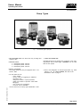
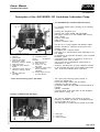
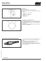
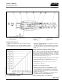
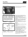
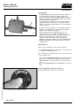
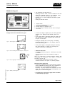
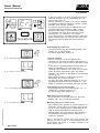
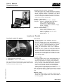
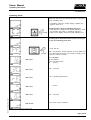
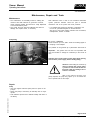
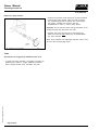
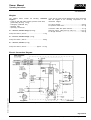
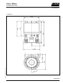
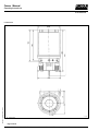
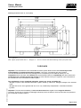
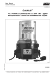
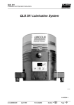
Owner Manual Operating Instructions 2.1A-30004-A02 Description of the QUICKDATA 233 Centralized Lubrication Pump The QUICKDATA 233 centralized lubrication pump - is a compact multiline pump consisting of the following components: Housing with integrated motor Reservoir with stirring paddle and fixed paddle Data logger (control p.c.b. and readable data memory) Pump element Pressure relief valve Filling device Electrical connection parts 4355a01 Fig. 2 - Components of pump 233 1 - Reservoir 2 - Pump element 3- Pressure relief valve 4 - Filling nipple, system Emergency lubrication possible 5 - Filling nipple, pump 6 - Adaptor for piston detector 7 - Display 8 - Momentary-contact switch for indication or setting of pause time 9 - Reading window for data logger 10 - Momentary-contact switch for additional lubrication 11 - Membrane key pad 12 - Piston detector 13 - Control p.c.b. with data logger 14 - Adaptor for power supply External illuminated pushbutton 15 - Closure plug for the use of a pump element Control and monitoring system QuickData - can drive up to 3 pump elements with different outputs - operates according to lubrication cycles (pause and operating times) - is equipped with a low-level control - can supply up to 300 lubrication points depending on the line lengths - is designed for the automatic lubrication of the connected lubrication points - is designed for the delivery of greases up to NLGI 2 at temperatures from -25°C to +70°C - can be used with low-temperature greases down to temperatures of -40°C During the operating time the pump dispenses lubricant to the connected lube points via one divider valve model SSV...-N and several divider valves model SSV... . - The control and monitoring system consists of: control p.c.b. MDF00 with built-on data logger module with IR interface membrane key pad with display IR interface module RS 232 (COM) for laptops without IR interface - Software QuickData - monitored divider valve model SSV...-N with integrated piston detector, see fig. 20. Control p.c.b. MDF 00 with data logger Subject to change without notice The control is installed in the housing of the pump behind the membrane key pad as an integrated printed circuit board MDF 00 (2, fig. 3). The data logger (1) is fixed onto the printed circuit board. 1 - Data logger 2 - Control p.c.b. 3 - Infrared interface 4358a01 Fig. 3 - Control p.c.b. MDF 00 with built-on data logger Page 7 of 36 LINCOLN GmbH & Co. KG Postfach 1263 D-69183 Walldorf Tel +49 (6227) 33-0 Fax +49 (6227) 33-259