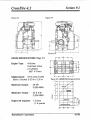
1
HYDRAMASTER
Corporation
11015
47th
Avenue
CrossFire
Machine
W, Mukilteo,
WA
98275
4.2
Serial Number
Copyright
q 1997
HYDRAMASTERe
Mukilteo,
Corporation
Washington
182-023
No part
electronic
of this manual
retrieval
may
systems)
be reproduced
without
or used in any form
the express
written
Revised
permission
August
or by any means
(i.e.
of the HYDRAMASTER”
15,
1997
graphic,
electronic,
Corporation.
photocopying
or
All rights reserved.
Table of Contents
Cross13re4.2
INFORMATION
Telephone
System
1-1
. . . . . . . . . . . . . . . . . . . . . . . . . . . . . . . . . . .
1-2
. . . . . . . . . . . . . . . . . . . . . . . . . . . . . . . . . . . .
1-3
Numbers
Operation
Machine
. . . . . . . . . . . . . . . . . . . . . . . . . . . . . . . . . . . .
Specifications
. . . . . . . . . . . . . . . . . . . . . . . . . . . . . . . . .
. . . . . . . . . . . . . . . . . . . . . . . . . . . .
1-6
. . . . . . . . . . . . . . . . . . . . . . . . . . . . . . . . .
1-6
Responsibility
I-a
Spare Parts Recommendation
Spare Parts List
Purchaser’s/Salesman’s
Vehicle
Water
Map
Machine
CLEANING
. . . . . . . . . . .
PROCEDURES
Drawings
Advisory
. . . . . . . . . . . . . . . . . . . . . . . 1-16
. . . . . . . . . . . . . . . . . . . . . . . . . . . . . 1-18
and Parts Lists
. . . . . . . . . . . . . . . . . . 1-19
. . . . . . . . . . . . . . . . . . . . . . . . . . . . . . . . . . . 2-1
. . . . . . . . . . . . . . . . . . . . . . . . . . . . . . . . . . . . . . . . . .
2-4
. . . . . . . . . . . . . . . . . . . . . . . . . . . . . . . . .
3-1
INSTRUCTIONS
Start Up
. . . . . . . . . . . . . . . . . . . . . . . . . . . . 1-1o
. . . . . . . . . . . . . . . . . . . . . . . . . . .. . . . . . 1-15
Disposal
Assembly
PH Chart
OPERATING
Suggestions
Precautions
Wastewater
. . . . . . . . . . . . . . . . . . . . . .
. . . . . . . . . . . . . . . . . . . . . . . . . . . . . . . . . . . 1-1o
Preparation
Installation
1-4
. . . . . . . . . . . . . . . . . . . . . . . . . . . . . . . . . . . . . . . . . . . 3-1
Shut Down
. . . . . . . . . . . . . . . . . . . . . . . . . . . . . . . . . . . . . . . . . 3-2
Precautions
. . . . . . . . . . . . . . . . . . . . . . . . . . . . . . . . . . . . . . . . . 3-4
Hydraikiaster Corporation
.
4/5/95
I
CrossFire 4.2
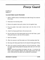
FREEZE GUARD
Vacuum
Freeze Guard Procedure
Anti-Freeze
WATER
AND
. . . . . . . . . . . . . . . . . . . . . . . . . . . . 4-1
. . .. . . . . . . . . . .
. . . . . . . . . . . . . . . . . . . . . . . . . . . . .
5-1
. . . . . . . . . . . . . . . . . . . . . . . . . . . . . . . . . . . . . . . . .
5-1
CHEMICAL
SYSTEMS
Water
Flow
Water
Flow Diagram
Chemical
. . . . . . . . . . . . . . . . . . . . . . . . . . . . . . . . . 4-2
Procedure
Proportioner
. . . . . . . . . . . . . . . . . . . . . . . . . . . . . . . . . . .
5-3
. . . . . . . . . . . . . . . . . . . . . . . . . . . . . . . . . .
5-4
. . . . . . . . . . . . . . . . . . . . . . . . . . .
5-5
. . . . . . . . . . . . . . . . . . . . . . . . . . . . . . . . . . . . .
6-1
. . . . . . . . . . . . . . . . . . . . . . . . . . . . . . . . . . . .
6-1
Diagram
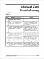
Tank Troubleshooting
PRESSURE
. . . . . . . . . . . . . . . . . . . . . . . . . . 4-1
PUMP
Pump Maintenance
Pump Service
(Wet End)
. . . . . . . . . . . . . . . . . . . . . . . . . . . . . . . .
6-3
Pump Service
(Hydraulic
End)
6-9
. . . . . . . . . . . . . . . . . . . . . . . . . . . . . . . . . 6-14
Pump Troubleshooting
Assembly
Drawing
Parts List (Wet
Assembly
(Wet
(Hydraulic
Parts List (Hydraulic
CLEANING
WAND
End)
. . . . . . . . . . . . . . . . . . . . . . . . . . . . 6-16
. . . . . . . . . . . . . . . . . . . . . . . . . . . . . . . . . . . 6-17
End)
Drawing
. . . . . . . . . . . . . . . . . . . . . . . . . . . .
End) . . . . . . . . . . . . . . . . . . . . . . . . . 6-18
. . . . . . . . . . . . . . . . . . . . . . . . . . . . . . . 6-19
End)
. . . . . . . . . . . . . . . . . . . . . . . . . . . . . . . . . . . . . . . .
7-1
Valve,
Jet, Wand
Assembly
. . . . . . . . . . . . . . . . . . . . . . .
7-1
Valve,
Jet, Wand
Parts List . . . . . . . . . . . . . . . . . . . . . . . . . . . . . .
7-4
. . . . . . . . . . . . . . . . . . . . . . . . . . . . . . . . . . . . . . . .
8-1
VACUUM
SYSTEM
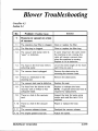
Blower
HydraMaster
Troubleshooting
Corporation
Drawings
. . . . . . . . . . . . . . . . . . . . . . . . . . . . . . . .
8-3
4/5/95
A
y
A
&
y
.
..
.
..
..
.
..
.
..
..
..
..
.
..
$
2
-A
.
.
.
.
.
.
.
.
.
.
.
.
.
.
.
.
.
.
2
w
0
&
A
o
9J
-.
0
A
.
m
3
z
5
C/l
c1
3-
(8
2
0
-.
-!
-.
z-.
2
-!
-.
s-.
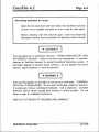
Introduction
CrossFire 4.2
Section 1-1
T
his manual contains installation and operation instructions as well as
information required for proper maintenance, adjustment and repair of
this unit. Since the first and most important part of repair work is the
correct diagnosis of the problem, component manual troubleshooting
charts have been included for your convenience.
Unlike a garden tractor,
lawn mower or cement mixer, all having one or
two functions to perform, the truck-mounted
many functions to perform simultaneously.
carpet cleaning
plant has
F
F
The engine has to run at a consistent RPM.
The vacuum has to pull air and dirty water
E
site.
The water pump provides stable pressure at proper water flow for
E
cleaning.
The chemical has to be injected into the water stream at the right
F
~
concentration.
The heating system must maintain proper heat.
The vacuum tank must store dirty water until drained.
back from cleaning
As you can see, it is not just a turn-key operation with one thing to worry
about, Does it start?!
HydraMaster
Corporation
4/5/95
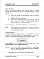
Section 1-2
CrossFire 4.2
II + WARNING+
The manufacturer
II
Ie manual to warn
uses this symbol throughout
of
possible injury or death.
.
1[ + CAUTION+
II
This symbol is used to warn of possible equipment
HOURS
Monday - Friday
8:00 am to 5:00 pm
PACIFIC STANDARD TIME
HydraMaster
Corporation
TELEPHONE
damage.
.
NUMBERS
(206) 775-7276
Parts
(206) 775-7275
Service
(800) 426-4225
Parts / Service FAX
7/18/95
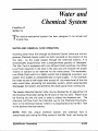
System Operation
CrossFire 4.2
Section 1-3
T
he CrossFire heat exchanger system is a highly engineered cleaning
plant designed by HydraMaster Corporation.
The system utilizes a
dynamic heating system comprised of three
exchangers for capturing “free heat. ”
separate
exhaust
heat
The water flow is as follows:
Water
is fed into the machine under tap pressure.
one pre-heater
and then is automatically
It flows through
combined
with a cleaning
solution as it enters the mix tank. The solution is then picked up by
the high pressure pump and pressurized to the desired level. The
water then splits flow, as demanded by the operator.
The majority
of the water flows to the by-pass valve assembly, then back through
the secondary exhaust heat exchanger, and back to the mix tank.
The water demanded by the operator flows from the water pump
through the primary exhaust heat exchanger then out to the cleaning
tool.
When the cleaning solution reaches a pre-set high temperature,
it is
released from the system and directed to the recovery tank. Then cool
water enters the system to regulate the temperature.
As there is no guess work in the manufacture
of these highly advanced
cleaning plants, there must be none in preparing it to get the job done in
the field. It is the purpose of this manual to help you properly understand,
maintain and service your cleaning plant. Follow the directions carefully
and you will be rewarded with years of profitable, trouble-free operation.
It is imperative
that no section
operation of this equipment.
HydraMaster
Corporation
be overlooked
when
preparing
for
4/5/95
“
Machine Specifications
CrossFire 4.2
Section 1-4
Frame:
Weight:
Cowling:
Engine:
Ignition:
Vacuum
Chemical
23”W
x 59”L x 37”H
Crossfire 4.2:
750 Ibs.
Steel with baked-on Epoxy finish.
Honda V-Twin
Electronic,
Blower:
Keystart.
Proprietary Dual Shaft Roots
45 RA1 J WhispAirTM
Electro-mechanical,
System:
Heating System:
Engine GX620
meter controlled.
Stainless steel exhaust exchanger.
2 Copper shell and tube exchangers.
1
Instruments:
Water Pressure gauge, liquid filled, 0-1000 PSI
Water Temperature gauge, 0-280° F
Vacuum Level gauge, 0-30” HG
Hour Meter, machine runtime
Keyed Ignition, start/stop
Chemical Flowmeter, clear acrylic, 0-10 GPH
Circuit Breakers, resettable
Recovery Tank:
70 gallon aluminum,
Cleaning
Wand:
HydraMaster
Epoxy finish.
Stainless steel with heat shield.
Corporation
Grip and replaceable
4/5/95
Sectionl=5
CrossFire 4.2
vacuum
lips with stainless steel solution valve.
1 /4”
High Pressure Hose:
rated to 1250 PSI.
Vacuum
Standard
Hose:
High temperature
2“ reinforced,
Equipment:
Machine
lined/vinyl
covered.
Hose
1 1/2” reinforced.
Power Console
Full Instrumentation
WhispAirTM Vacuum Blower
CrossFireTM Water Heating Package
Deluxe Sound Suppression
Vacuum Recovery Tank
Package
Carpet Cleaning Wand
Chemical Jug
Chemical Jug Holder
Chemical Jug Fill Line
150 ft, 2“ Vacuum Hose
10 ft, 1 1/2” Wand Whip-line
10 ft, 1 1/2” Recovery Drain Line
50 ft, Water Supply Line
150 ft, Super Flex Solution Line
Dual-Wand Vacuum Fittings
Dual-Wand Solution Fittings
Freeze Guard System
Battery Box with Holder
Telescoping Console Legs with Casters
Van Decal Package
Van Installation Kit
Operation Manual
HydraMaster Jacket
HydraMaster
Corporation
4/5/95
Spare Parts
CrossFire 4.2
Section 1-6
D
own-time on the unit can be very expensive, because your truckmounted unit is capable of generating several hundred dollars per
day. In order to minimize such down-time, it is strongly recommended by
the manufacturer
below.
that you purchase and keep in your truck the parts listed
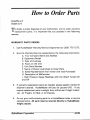
Parts Orders
To expedite your parts needs, please call your sales representative.
In
most instances, he either stocks or has access to parts through a regional
If further assistance is needed, contact the factory and
service center.
coordinate your needs. If this becomes necessary, always indicate the
method of shipment you desire, i.e. UPS, Blue Label, Air Freight, Air
Express, etc.
HydraMaster
Parts Dept. Phone
. . . . . . . .
HydraMaster
Parts Dept. Toll Free Fax . . . .
(206)
775-7276
1-800-426-4225
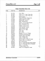
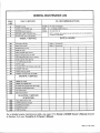
Parts List (078-096)
PART NO
DESCRIPTION
QTY
010-014
Belt, #9341
010-018
Belt, BX 59-MultiCat
Pump Drive
018-004
Breaker,
25 amp Circuit
20 amp Circuit
Drive
1“
2
1
1
018-005
Breaker,
025-011
Cable, Aqua 5’ Choke
1
049-046
Filter, Oil -20
1
049-007
Filter, S/S Vacuum
HydraMaster
Corporation
HP Honda
Pump
1
4/5/’95
sectionl”7
CrossFire 4.2
QTY
PART NO
DESCRIPTION
049-015
Filter,
049-016
Filter, 1/4” Replacement
049-023
Screen,
1/2” Replacement
Y
1
1
1
Garden Hose
HP Honda
1
049-045
Filter, Air -20
049-030
Filter Bag, 92+
Truck Mount
2
052-050
Quick Connect,
440
3
052-051
Quick Connect,
440
Female
052-052
Quick Connect,
660
Male
052-053
Quick Connect,
660
Female
057-043
Gasket,
076-005
Jet, #6 S/S - Hydra Hoe
074-003
Gauge,
074-020
Meter,
078-018
Kit, Diaphragm
078-015
Kit, Chem Flowmeter
1
078-019
Kit, H/M Solution
1
078-101
Kit, Seal & Spring Hi PSI
1
106-017
Plug, 20 HP Honda,
2
131-037
Wrap,
149-011
Thermostat,
Aqua 185 Deg.
149-013
Sensor,
Degree - Hot
Recovery
Male
Tank - All
Hi PSI (O-1 000)
Chemical
Flow - CDS
3 GPM H-M Hi PSI
Valve
Spark
Exhaust insulation
245
1
1
1
2
157-001
Switch,
Tethered
157-007
Switch,
12V DC Lited
1
157-008
Switch,
Ignition
1
1 !57-022
Switch,
Relay - A/C,
157-111
Switch,
Chrome
169-022
Valve,
169-062
169-120
IIydmlfaster
Mercury
1
B/C, CDS
Momentary
2
1
1 1/2” Full Port
1
Valve,
1/4 Anti-Siphon
1
Valve,
Chemical
1
Corporation
System
4/5/95
—
Responsibilities
CrossFire 4.2
Section l-8
T
he Purchaser’s
responsibilities
are:
Prior to arrival of unit, install 5/8” exterior plywood
flooring in the vehicle
and cover it with artificial turf.
Purchase heavy duty 42 - 60 amp hour battery and have the battery
[f the battery is not fully charged, damage can
‘slow’ charge if new.
occur to the engine charging regulator.
Reading of owner’s manual: It is the purchaser’s responsibility to read the
unit operation manual and to familiarize himself with the information
contained therein.
Special attention should be paid to ail Cautions and
Warnings.
The Sales Representative’s
ACCEPTANCE
1.
responsibilities
are:
OF SHIPMENT:
If the unit shows
any outward
signs of damage, do not sign the
delivery receipt until you have closely inspected the unit and noted
any damage on the delivery receipt.
2. The salesman from whom you purchased your unit is responsible for
supervising the correct installation of the unit in your vehicle and
HydraMaster
Corporation
4/5/95
-
Section 1-9
CrossFire 4.2
thoroughly training you in its operation,
CORRECT
INSTALLATION
Installation
maintenance
and precautions.
INCLUDES:
of through-floor
fittings for gasoline fuel lines;
Placing the unit and recovery tank in your vehicle and securing them
with bolts or tie down cleats;
Connecting
gasoline lines;
Connecting
the battery;
Checking
the pump, vacuum
blower and engine oil levels prior to
staring the unit;
Starting the unit to check engine and see that all systems function
normally;
Checking all hoses, wands,
TRAINING
etc. for correct operation.
SHALL INCLUDE:
A thorough
review of the operation manual with purchaser;
Instruction and familiarization
in: how to correctly start up and shut
down the unit, how to correctly clean with the unit, where and how
often to check and change component oil levels, how the unit’s
systems work, how to troubleshoot the unit, how to do basic
repairs, safety precautions and their importance, freezing damage
and how to avoid it, hard water damage and how to avoid it;
A thorough review of the unit warranty
HydraMaster
Corporation
and warranty
procedures.
4/5/95
Vehicle Prep
CrossFire 4.2
Section 1-10
T
he preferable vehicle for a CrossFire or ProFire installation is a cargo
van with a heavy-duty suspension package. The van should have 3/4
ton capacity.
TRUCK
The
PREPARATION
manufacturer
recommends
the
installation
of plywood
flooring,
covered with polypropylene backed astroturf (do not use rubber-backed),
in the vehicle prior to installation of machine.
Be cautious when drilling any holes through the van floor.
Many vans have critical components mounted directly below
the van floor that could be damaged by a misplaced drill bit.
This
(See product Support Bulletins 92102,
the end of this manual. )
94062
provides
rather than
a metal-to-cushion
insulation and makes an attractive
color keyed to the van interior.
mounting
van interior.
and 94063
at
metal-to-metal,
The astroturf
should be
Materials Needed:
1. 2 sheets 4x8x5/s” exterior plywood
2. 6’x I 2’ piece of commercial astroturf
3. 16- 1 %” sheet metal screws
4. 1 quart marine adhesive (optional)
HydraMaster
Corporation
4/5/95
Section 1-11
CrossFire 4.2
5. 1 staple hammer with ?4” staples
(See illustration for correct placement of plywood
flooring)
ROOF VENTS
HydraMaster
strongly recommends
installation
of roof vents in all
When installing equipment
with propane
truckmount
installations.
heaters, these must be vented through the roof of the van.
PLACEMENT
OF UNIT IN VEHICLE
There are two recommended
unit placements
illustrated in the following diagrams.
A.
SIDE
DOOR:
Most
installations
described
are side door.
below
and
This provides
rear
access for accessories and hoses as well as unobstructed access to the
component/working
side of the machine, thus making it a bit easier to
perform maintenance and/or repair without removing the unit from the
truck.
B. REAR DOOR: Although this location partly limits working access, it
does direct the noise away from the cleaning site. Some cleaners in the
colder areas prefer this location because it puts the weight over the rear
Rear mounting requires the
wheels for better traction in ice and snow.
unit to be slid to the right side as far as possible. This not only provides
adequate working space on the component side of the unit but also
improves weight distribution inside the van (engine and component weight
line up over drive shaft). Also, it is physically easier to load the unit into
the rear door due to the height of the van bed.
HydraMaster
Corporation
4/5/95
“
Section 1-12
CrossFire 4.2
gure 1-1: Plywood Installation
‘igure 1-2: Astroturf
and Roof Vent
I
‘igure 1-3: Machine Tie Down Cleats
.
Nlinimurn
HydraMaster
Corporation
4/5/95
Section 1-13
CrossFire 4.2
+ WARNING
+
Ensure that the machine is well secured to the floor of the van with the
A sudden or crash stop will cause the machine to
hardware supplied.
rocket forward, ail 750 Ibs. worth!
Protect yourself and the machine.
SECURE IT!
-1
[t is recommended by the manufacturer that the exhaust from the front of
the machine be vented down under the truck to prevent carbon monoxide
Always park the truck so the exhaust is
from entering the job site.
blowing
away from the job site.
The manufacturer
also recommends
the installation
of aluminum
vents in
the truck roof to allow heat to escape.
Mount a fire extinguisher just inside the rear or side door for emergencies.
II
+ WARNING
+
II
q
P
Never operate this machine with a portable gas can inside the truck.
Doing so increases the risk of a fire or explosion.
11
II +WARNING
([
+
II
.
Transportation
in a vehicle of any vented fuel container that presently
holds or has ever held a flammable liquid is strictly forbidden
by
HydraMaster Corporation and by federal and state regulation.
HydraMaster
Corporation
4/5/95
Section 1-14
CrossFire 4.2
+ WARNING
+
Do not use a portable propane tank inside of the truck
dangerous and illegal in most states.
or van.
It is
t.
HydraMaster
Corporation
4/5/95
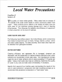
Local Water Precautions
CrossFire 4.2
Section 1-15
T
he quality
of water
varies greatly.
Many areas have an excess
of
minerals in the water which results in what is commonly called “hard
water”. These minerals tend to adhere to the insides of heater coils and
other
parts
of the
machines
causing
damage
and a loss of cleaning
effectiveness.
This influences the reliability and efficiency
in direct proportion to the level of hardness.
HARD WATER
of equipment
AREA MAP
The following map defines areas in the United States which compromise
fluid related components such as hoses, fittings, heaters, pumps, valves
and water cooled engines. For other countries, hard water area maps can
be obtained
WATER
from geological societies.
SOFTENER
Cleaning
efficiency
and equipment
life is increased,
chemical
use
decreased, and the appearance of cleaned carpets enhanced when water
softeners are incorporated in hard water areas. The manufacturer strongly
urges the use of water softener units in areas exceeding 3 1/2 grains per
gallon. Using a hard water area map as a reference, determine the quality
of water in your area and take action immediately, if necessary.
Reports from several of our machine users commending the results of the
use of water softeners in conjunction with their machines prompts us to
recommend the procedure to everyone in a “hard water” area.
HydraMaster
Corporation
4/5/95
.
Section 1-16
CrossFire 4.2
The relatively low cost of a water softener service is more than made up
for in the increased life of machine parts and continued
cleaning
efficiency. The water softener will also increase the effectiveness of the
cleaning chemical being used and, therefore, less chemical will be needed.
Contact a water softener distributor in your area for information on the
rental of a simple water treatment unit to carry in your truck. Be sure to
change the water softener in accordance with the capability of the
softener. For example: If the softener will treat 900 gallons of water and
the machine uses an average of 30 gallons per hour, for an average of 5
hours a day, this equals 150 gallons per day. In 6 days the machine
would use 900 gallons of water.
Therefore,
the softener
would need to
be changed every 6 working days for maximum softening.
WASTE
WATER
DISPOSAL
ADVISORY
There are laws in most communities prohibiting the dumping of recovered
“gray” water from carpet cleaning in any place but a sanitary treatment
system.
This
cleaning
rinse water,
recovered
into your
unit’s
vacuum
contains materials such as detergents.
These must be processed
being safe for streams, rivers and reservoirs.
tank,
before
IN ACCORDANCE WITH THE EPA, STATE AND LOCAL LAWS, DO NOT
DISPOSE
OF WASTE
WATER
INTO GUTTERS,
STORM
DRAINS,
STREAMS, RESERVOIRS, ETC.
In most
cases,
an acceptable
method
of waste
water
disposal
is to
discharge into a municipal sewage treatment system after first filtering out
solid material such as carpet fiber. Access to the sanitary system can be
obtained through a toilet, laundry drain, RV dump, etc. Permission should
first be obtained from any concerned party or agency.
HydraMaster
Corporation
4/5/95
.
CrossFire 4.2
Section 1-17
One disposal method which usually complies with the law is to
accumulate the waste water and haul it to an appropriate dump site.
Another solution to the disposal problem is to equip yourself with an
These systems are designed to remove
Automatic Pump-Out System.
waste water from the extractor’s recovery system and actively pump the
water through hoses to a suitable disposal drain. Properly designed, they
will continuously
monitor the level of waste water and pump it out
The hidden benefit of this
simultaneously
to the cleaning operation.
process is that the operator does not have to stop his cleaning to empty
the recovery tank. HydraMaster makes an A.P. O. System available which
can be ordered with new equipment or installed later.
Always
The penalties for non-compliance can be serious.
laws and regulations to be sure you are in compliance.
HydraMaster
Corporation
check
local
4/5/95
Section 1-18
CrossFire 4.2
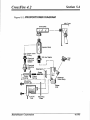
Figure 1-4:
Hard Water
Map
/-’>
Grains
Per Gallon
I
I ~ - 31/2
7-
10Y2
101/2 and above
HydraMaster
Corporation
4/5/95
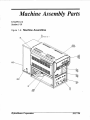
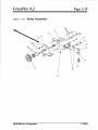
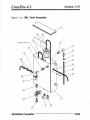
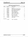
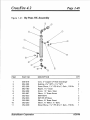
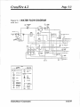
Machine Assembly Parts
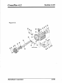
CrosslVre 4.2
Section1-19
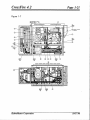
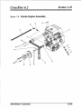
Figure 1-5:
Assemblies
Machine
03
813
@l
OPPOSITE ITEM 14
P
47 70
12 45 62
m=-.
(5?+
48
11
7085
HydraMaster
Corporation
10!17/96
CrossFire 4.2
Page 1-20
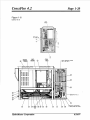
Figure 1-6
D2950,
Rev B
59 7“
(69 2217
?
OEHtND(FEW32
“UT -0 O“MP 50,
ON RFIIWCR, TANK
w’;
@“
-’a
\
9
37
52
77 70
UNION CONNECTION
BEIWEEN
IKM 5 ANO ITEM 6
5944
~
t
\I
[
\
/
IIMHI
MmHll
Mull
HydraMaster
Corporah”on
6/24/97
CrossFire 4.2
Page 1-21
Figure 1-7
HOSE ROWES
TO lHE
PRESSURE GALJGE
63
70
E
43
81 AROUNO EXHAUST
MANIFOLD
9
-----+
50
@------
HydraMaster
Corporation
10/17/96
CrossFire 4.2
Page I-22
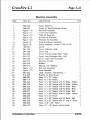
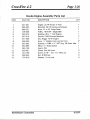
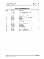
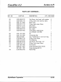
Machine
Assembly
QTY
PART NO
DESCRIPTION
055-015
Frame,
Multi Fire
2
055-030
Frame,
HX Heat Exchanger
3
Figure 1-16
Mid Panel Assembly
1
4
Figure 1-17
Lower Panel Assembly
1
5
Figure 1-19
Triple HX Assembly
1
6
Figure 1-21
By-Pass HX Assembly
1
7
Figure 1-20
Preheater
1
8
Figure 1-9
Pump and Blower Assembly
9
Figure 1-8
Engine Assembly,
10
100-037
Louver
11
041-162
Cover,
12
041-160
Cover, Top
13
041-040
Cover,
Heat Exchanger
Side - Right
1
14
041-041
Cover,
Heat Exchanger
Side - Left
1
15
041-032
Cover,
Upper Heat Exchanger
16
042-013
Housing,
17
093-029
Muff Ier
18
093-017
Silencer,
19
Figure 1-12
Mix Tank Assembly
1
20
Figure 1-15
Dash Assembly
1
21
081-032
Label, “Caution
22
015-236
Bracket,
23
068-083
Hose,
3/8”
24
068-114
Hose,
3/8”
25
068-222
Hose,
k” x 62” Rubber with 3/s” Ends - Yellow
1
26
068-223
Hose,
?4” x 58” Rubber with 3A” Ends - Yellow
1
27
068-224
Hose,
k” x 67” Rubber with 318”Ends - Blue
1
28
068-225
Hose,
?4” x 44” Rubber with
Ends - Blue
1
29
068-227
Hose,
YZ” x 51” Rubber with %“ Ends - Red
1.
30
068-228
Hose,
%“ x 36” Rubber with %“ Ends - Yellow
1
31
068-237
Hose, 3A” x 40” Throb
1
32
068-233
Hose,
1
33
068-234
Hose,
34
068-235
Hose, 3/1 6“ x 59” Teflon
35
068-170
Hose,
ITEM
1
HydraMaster
Corporation
1
Mount
1
HX Assembly
1
Honda V-Twin
1
20 HP
1
Deflector
1
- Side
1
1
Air Duct
1
1
2X”
Whisper
1
- Hot Surface...
”
1
2
Air Duct Mount
x
70’”
Teflon
x
!50’”
1
1
Teflon
3/8”
k” x 55” Rubber with 3%” Ends - Red
3/8”
x
82” Rubber with 3A” and ?4” Ends
%“ x 18“ Steam without
1
1
Ends
1
6/20/96
1
CrossFire 4.2
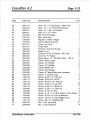
Page 1=23
1.
ITEM
PART NO
DESCRIPTION
QTY
36
068-144
Hose,
15\a” x 3“ Red Stripe - Glass Pack
1
37
068-275
Hose,
1%“ x 17“ Red Stripe
1
38
15\a” x 50” s/s Exhaust
Exhaust
1
068-231
Hose,
40
068-071
Hose, %“ x 12“ Teflon
1
41
010-050
Belt, 5VX-61
1
42
010-014
Belt, Pump Drive
43
135-035
Regulator,
44
157-016
Switch,
45
067-013
Hinge, Top Cover
46
067-015
Hinge,
47
108-024
Protector,
48
089-003
Magnet,
49
060-008
Grommet,
5/1 6“ ID Rubber - Mix Tank
8
50
060-007
Grommet,
%“ Rubber
2
51
052-209
Street
52
033-007
Clamp,
#28 s/s Hose
2
53
033-055
Clamp,
3?4” Muffler
2
54
033-058
Clamp,
2!4”
3
55
033-028
Clamp,
Muffler
15/8”
2
56
033-038
Clamp,
Hose Hanger
1
57
033-040
Clamp,
%” Spring-Rake
58
033-057
Clamp,
1” Cushion Loop
4
59
143-132
Screw,
10-24
x %” HHC s/s
2
60
143-112
Screw,
10-24
x 34” HHCS
4
61
143-133
Screw,
10-24
x 1 %” HHC s/s
2
62
143-126
Screw,
10-24
x %” s/s HHC
63
143-115
Screw,
%-20
x %“ HHCS s/s
4
64
143-004
Screw,
%-20
x 1 %“ HHC s/s
4
65
143-093
Screw,
%-1 6 x 2“ HHC
4
66
143-039
Screw,
%-1 3 x 1 %” HHC Grade 5, Zinc Plated
4
67
143-060
Screw,
10-24
x %“ Flat Hd Machine
3
68
143-063
Screw,
10-24
x ?4” Flat Phillips Hd s/s
2
69
#8 x %“ HXWSHD
Honda Voltage
1
1
1
1
Dash
Grommet
2
Bumper
2
Arm
Elbow,
143-119
Screw,
094-034
Nut,
10-24
71
094-009
Nut,
%-20
Corporation
1
Starter Solenoid
70
HydraMaster
O Single
1 %” IPS MXF,
Galv.,
150 lb.
Muffler
S/S
S/S
1
and Accessory
SM
1
19
2
Nylock
31
Nylock
4
10/1 7/96
-
CrossFire 4.2
Page 1-24
QTY
ITEM
PART NO
DESCRIPTION
72
094-015
Nut, 3A-16 Two-Way
Lock, Zinc Plated
Steel
4
73
094-037
Nut,
%-13
Two-Way
Lock, Zinc Plated
Steel
4
74
094-007
Nut,
%-20
Whiz
2
7!5
094-016
Nut, 3\&l 6 Whiz
2
76
094-039
Nut, % s/s Wing
2
77
174-001
Washer,
#1 O s/s Flat
2
78
174-003
Washer,
?4” s/s Flat
4
79
174-005
Washer,
3A Flat
4
80
174-007
Washer,
% Flat
4
81
131-009
Insulation,
82
131-037
Wrap,
83
131-003
Gasket,
84
131-027
Trimlokr
85
143-168
Screw,
86
052-358
Insert,
#121 2 Brass
1
87
052-129
Insert,
#81 2
1
88
177-004
Wheel,
89
600-001-001
Exhaust
Insulation
- 2“ x 50’
10-24
x %” BTN HD s/s
3“ TR MNT Caster
w/ Sq. Tube
2
4
4
Leg, Silver
105-012
Plate, Machine
Serial ID
91
140-015
Rivet,
Aluminum
x
%”
92
033-025
Clamp,
1” Tie Wrap
93
154-002
Spacer,
Mix Tank Mounting
Corporation
56”
CF Brow Trim
1/’8”
1
1 Ft
Trim
90
HydraMaster
1
1‘ x %“ x 15’ Duct
1
Pop
Harness
Mounting
2
13
4
6/24/97
Section 1-25
CrossFire 4.2
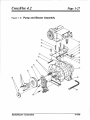
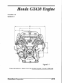
Figure 1-8:
Honda
Engine Assembly
o-fq
1’
HydraMaster
Corporation
3/6/96
I
CrossFire 4.2
Honda
ITEM
PART NO
Page 1-26
Engine Assembly
Parts List
QTY
DESCRIPTION
1
047-001
Engine, 20 HP Honda V-Twin
1
2
090-002
Manifold,
1
3
068-221
Hose, 3A” x 24” Pump Drain
1
4
109-026
Pulley,
- Single Belt
1
5
020-016
Bushing,
#B x 1” Hub Engine
1
6
057-016
Gasket,
7
077-006
Key, Briggs 16 HP Engine
1
8
068-026
Hose,
3“
9
052-063
Bushing,
10
052-085
Elbow,
11
052-109
Insert,
12
033-031
Clamp,
Size #4 Hose
13
143-158
Screw,
5/1 6“ - 18xlfi’’HHc
14
094-043
Nut, 8 MM Hex
4
15
174-019
Washer,
4
HydraMaster
Corporation
20 HP Honda s/s Exhaust
1 B 5V54
P220
Exhaust
2
Manifold
%” Rubber Fuel Line Per Foot
14 MM x %“ NPT Eng. Oil Drain Adp.
1
IA” Brass Street
1
#24
% s/s Lock
1
2
s/s
3
8/15/97
CrossFire 4.2
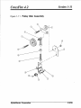
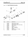
Figure 1-9:
Pump and
HydraMaster
Corporation
Page 1-27
4/4/96
CrossFire 4.2
Page 1-28
Pump and Blower Assembly
ITEM
PART NO
DESCRIPTION
QTY
1
111-022
Blower,
2
Figure 1-10
Pump Assembly
3
015-250
Bracket,
4
Figure 1-11
Pulley Idler Assembly
1
5
109-026
Pulley,
1
6
109-006
Pulley, 2%” x
7
020-017
Bushing,
8
052-069
Nipple,
9
052-293
Insert,
10
052-092
Tee,
4.2 Hydra Whisper
1
4.2 Blower Collector
1 B 5V54
Pump
7/8”
1
1
%“ Brass Hex
1
#23
1
1
Brass
1
Brass street
052-084
Elbow,
1/8”
12
------------
Fitting,
Vacuum
13
143-139
Screw,
3%” - 16 x 4“ HHCS
14
143-020
Screw,
3A” -16
15
143-097
Screw,
16
174-029
Washer,
17
094-015
Nut, 3%-16
%“ -16
3/8”
Gauge*
x 1 Z”
x 2?4”
2-Way
HHC Grade
Screw,
Key, #3 and #4 Vacuum
20
052-085
Elbow,
21
068-221
Hose,
x
1
5 Zinc
1
4
4
5 Zinc
Pump Drive
X” Brass Street
3/8”
8
Grade 5 HHCS
16 x 1 %“ HHC Grade
143-019
077-001
-
Grade
Lock Nut, Zinc Plated
18
3/8
1
SS Rubber Back
19
13ydraMaster Corporation
1
#B x 7/8” Hub Blower
‘/8”
This fitting comes with part no. 074-006
Box
- Single Belt
11
* Note:
1
24” Pump Drain
Steel
2
3
2
1
1
and is not available separately.
4[30/96
CrossFire 4.2
Figure
1-10:
Page 1-29
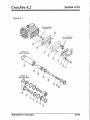
Pump Assembly
I
Ilydraillaster
Corporation
7/16/96
CrossFire 4.2
Page 1-30
Pump Assembly
ITEM
Parts List
QTY
PART NO
DESCRIPTION
1
111-050
Pump, 3 GPM High PSI - Hydra
1
2
015-232
Bracket,
1
Pump Mount
3
109-022
Pulley, #AK 54 H Pump
1
4
020-019
Bushing,
1
5
143-022
Screw,
6
052-020
6MA-6UFS
1
7
052-001
2M-2UFS
1
8
052-060
Bushing,
9
052-023
6MT-6F-6F
Brass
1
10
052-087
Elbow,
Brass Street
1
11
052-038
8M-I
12
106-003
Plug,
13
174-005
Washer,
14
#H x
7/8”
3A” - 16 x 1 %“ HHC Grade
8
3!4M x % F Brass
k”
4
1
1
2UFS
Brass
1
3A” Flat
4
094-014
Nut, % - 16 Hex
4
15
077-001
Key, #3 and #4 Vacuum
16
052-084
Elbow,
17
068-256
Hose, 3?s”x 24” Pump Drain
3/8”
Pump Drive
%“ Brass Street
1
1
1
I
HydraMaster
Corporation
7116/96
Section 1-31
CrossFire 4.2
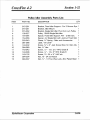
Figure 1-11:
Pulley
/
%
HydraMaster
Corporah”on
3/6/96
Section 1-32
CrossFire 4.2
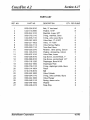
Pulley Idler Assembly
Parts List
QTY
PART NO
DESCRIPTION
1
015-261
Bracket,
Fixed Idler Support-
2
015-251
Bracket,
Idler Mount
ITEM
For2
Groove
3
015-262
Bracket,
109-027
Pulley,
Single Belt idler Pivot Arrow/o
5
154-054
Spacer,
6
154-056
Spacer,
4.2
7
033-040
Clampr
%” Spring - Rake and Accessories
8
081-066
Label, “Oil Level”
9
143-202
Screw,
10
094-080
Nut, %” Hex
11
143-042
Screw,
M” - 13 x 2k”
12
143-036
Screw,
%” - 13 x 3“ HHC Grade 8
13
143-132
Screw,
10-24
Fixed Idler Support
094-034
Nut, 10-24
094-037
Nut,
1
1
Arm -2
Belt Sys.
Single Belt with Jacknut
1
Fixed Idler
1
1
1
%“ x 3“ Jack Screw
15
Corporation
Pulley
15 V4B Single Belt Idler
14
1
1
4
HydraMaster
Sys.
Mod.
for Idler Adj.
1
1
1
HHC Grade 8
1
1
x %“ HHC s/s
S/S
1
Nylock
% “ - 13 Two Way
Lock, Zinc Plated Steel
1
3/6/96
Section 1-33
CrossFire 4.2
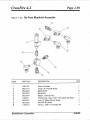
Figure 1-1 Z: Mix
Tank Assembly
@L.
%oq
0.
LOWER
MIX
TANK
QW
\\
FL-. .
\
w
Q
14
w“
$
I
/
\
HydraMaster
Corporation
1
3/6/96
—
Section 1-34
CrossFire 4.2
Mix Tank Assembly
ITEM
PART NO
DESCRIPTION
1
159-059
Tank,
2
041-159
Cover,
3
157-001
Switch,
Parts List
QTY
1
’95 s/s Mix
’95 Chemical
Tethered
1
Mix Tank s/s
Mercury
2
Float -250
1
4
169-120
Valve,
5
181-008
Venturi,
6
068-326
Hose, %%Clear with Braid Sol.
7
033-004
Clamp,
8
052-104
Insertr #66
1
9
052-087
Elbow,
%” Brass Street
1
10
052-086
Elbow,
Brass Street
1
11
052-142
Elbow, %“ F x F Brass
1
12
052-074
Nipple, 3%Brass Hex
2
13
052-019
6M-6UFS
3
14
108-050
Protector,
Electric Cord Lock Bulk Head Fitting
1
15
060-008
Grommet,
5/1 6“ ID Rubber - Mix Tank
2
16
033-021
Clamp,
?4 Nylon Hose
1
17
143-169
Screw,
10-24
1
18
174-036
Washerr
19
094-034
Nut, 10-24
131-009
Insulation,
Chemical
System
Solenoid
-12
Volt
1
Low PSI Injector
15”
1
Size 6 Mini Hose
3/8”
x !4” HHCS
#1 O SS Flat - Rubber
S/S
Nylok
Back
1
1
Not Shown:
HydraMaster
Corporation
1‘ x %“ x 15’ Duct
1
3/6/96
Page 1-35
CrossFire 4.2
Figure 1-13: Recovery
D2820,
Tank Assembly
Rev B
I
il
I
I
I
HydraMaster
Corporation
7//21/97
CrossFire 4.2
Recovery
Page 1-36
Tank Assembly
Parts List
QTY
PART NO
DESCRIPTION
1
159-040
Tank,
2
Figure 1-14
Dual Inlet Lid Assembly
1
4
166-002
Tray,
1
5
052-332
Adapter,
Vacuum
6
052-342
Adapter,
3“ NPT x 2“ FPT - PVC
7
012-002
Block, 6 Post Terminal
1
8
052-253
Elbow,
1A” Male x %” Barb
1
9
052-086
Elbow,
3/s” Brass Street
1
10
049-007
Filter, s/s Vacuum
11
052-105
Insert,
#68
1
1
ITEM
Recovery
1
Chemical
Soap Jug
Tank Outlet
1
1
1
Pump-Blower
12
052-109
Insert,
13
052-073
Nipple,
#F24
% “ x 3/i” Brass Hex
14
052-182
Nipple,
1 %” Close - Galv.
15
105-011
Plate, Filter Bag Support
1
2
16
105-005
Plate, Vacuum
17
052-436
Quick Connect,
18
155-002
Spring, s/s Vacuum
1
Steel
1
Relief
1
%” F x %” FPT
2
Relief Valve
1
19
157-001
Switch,
Tethered
20
131-028
Gasket,
Trimlok
Recovery
Tank
21
169-120
Valve,
Chemical
System
Solenoid,
22
169-022
Valve,
1 %” Full Port Brass Dump
23
143-009
Screw,
24
094-010
Nut,
25
174-003
Washer,
26
174-005
Washer,
27
052-083
Elbow,
28
033-021
Clamp,
% Nylon Hose
2
29
143-1’32
Screw,
10-24
2
30
094-034
Nut, 10-24
31
143-051
Screw,
32
094-059
Nut, 8-32
33
131-003
Gasket,
34
081-070
Label, Small Caution
35
060-002
Grommet,
HydraMaster
Corporation
% -20
Mercury
x 2%”
Floated
HHC s/s
-25
Deg.
14Ft
12 Volt
1
1
2
s/s Hex
4
%” s/s Flat
4
Flat
1
?4 -20
3/8”
3/8”
6rass 45 Street
x %“ HHC s/s
S/S
8-32
S/S
1
2.
Nylock
x %“ Phil Binder Head
2
2
Nylock
32”
Trim
Label
Large Wiring
1
1
7/21/97
CrossFire 4.2
Figure 1-14:
Dual Inlet Lid Assembly
HydraMaster
Corporation
Page 1-37
2/20/97
CrossFire 4.2
Page 1-38
Dual Inlet Lid Assembly
ITEM
PART NO
DESCRIPTION
1
041-087
Lid, Front Vacuum
2
041-086
Lid, Rear Vacuum
Parts List
QTY
1
Tank
Tank
1
Tank
2
Flat Head Machine
6
3
067-017
Hinge Set, Left - Recovery
4
143-060
Screw,
10-24
5
052-222
Elbow,
2“ Comb
6
057-015
Gasket,
7
052-219
Adapter,
8
125-014
Pipe, 2“ Sch. 40,
9
052-404
Adapter,
10
049-030
Filter Bag
11
078-039
Kit, Vacuum
12
143-166
Screw,
HydraMaster
Corporation
1 k”
x
3/8”
- Insert x FPT
Bulkhead
Fitting
2“ NPT x 2“ F Slip ABS
PVC x 20 Feet Long
3“ F Slip x 2“ F Slip
10-24
2
2
2
2
2
2
Inlet Stopper
x 34 s/s HHC
1
1
2/20/97
CrossFire 4.2
Figure 1-15:
Page 1-39
Dash Assembly
@@-----
--mm
)
mtiMl
Mu
/
HydraMaster
Corporation
c
\
6/20/96
CrossFire 4.2
Page 1-40
Dash Assembly
Parts List
QTY
PART NO
DESCRIPTION
1
041-182
Cover,
2
081-063
Label, CF 4.2-
Dash 2-Piece
Set
1
3
081-063
Label, CF 4.2-
Dash 2-Piece
Set
1
4
157-008
Switch,
5
074-001
Gauge,
S/W Water
6
074-003
Gauge,
High PSI (O-1 000)
1
7
074-006
Gauge,
Isspro Vacuum
1
8
074-020
Meter,
9
157-007
Switch,
10
074-011
Meter,
11
018-004
Breaker,
25 Amp Circuit
1
12
018-005
Breaker,
20 Amp Circuit
1
13
084-006
Lamp, Red Pilot - Round
3
14
033-049
Clamp,
Indicator
Light
3
15
052-253
Elbow,
%“ x %” Barb
1
16
052-097
Insert, #24
17
052-011
4FA - 4UFS
ITEM
Brow
1
Ignition
1
Chemical
Temperature
Flow
1
12 V DC Lighted
Rectangular
1
Rocker
2
1
Hour
1
1
% f~M x
1/8”
F
Brass
1
18
052-059
Bushing,
19
108-024
Protector,
20
015-005
Bracket,
21
086-001
Latch,
22
033-021
Clamp,
% Nylon Hose
1
23
143-061
Screw,
10-24
x %” Rnd Phl Head
2
24
143-132
Screw,
10-24
x %” HHC s/s
1
25
094-027
Nut, 10-24
26
094-025
27
094-024
Nut, 3/8-32
Nut, 3/8 -32
28
140-006
Rivet,
Grommet
Chem.
Cowling
Bumper
Flow Meter
1
Hood
1
Half Nut Brass Nickle Plated
Knurled Finish for Breakers
131-027
TrimLok,
081-081
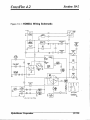
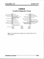
Label, CF 4.2 Diagnostic
2
2
1
X x % s/s Pop
30
Corporation
2
s/s Hex
29
HydraMaster
1
lFt-
CF Brow Trim
Center
1
6/’20/96
CrossFire 4.2
Figure 1-16:
Page 1-41
Mid panel Assembly
3
\
““b
1
b
2
HydraMaster
Corporation
6/20/96
CrossFire 4.2
Page 1-42
Mid Panel Assembly
ITEM
Parts List
QTY
PART NO
DESCRIPTION
1
100-041
Panelr Mid
2
015-248
Bracket,
3
081-031
Label, Engine Throttle
4
105-020
Plate, HydraMaster
5
012-010
Block, 10 Post Terminal
2
6
086-001
Latch,
1
7
029-004
Throttle,
8
033-057
Clamp,
1” Cushion
9
143-132
Screw,
10-24
10
094-034
Nut,
11
140-006
Rivet,
12
131-027
Trimlok,
13
143-126
Screw,
10-24
14
157-022
Switch,
Relay
161-009
Tape,
1
Throttle
Assembly
Cowling
Mount
Adjustment
Cast Name
Hood
Adjustable
Cable
1
1
1
1
Loop
1
x %” HHC s/s
5
Nylock
12
?4 x % s/s Pop
2
10-24
S/S
CF Brow Trim
x %” s/s HHC
1 Ft
7
3
Not Shown:
HydraMaster
Corporation
1” Double
Back
5“
6/20/96
CrossFire 4.2
Lower
Figure 1-17:
Page 1-43
Panel Assembly
.--”
HydraMaster
Corporation
6/20/96
I
CrossFire 4.2
I
Lower
Page 1-44
Panel Assembly
Parts List
QTY
ITEM
PART NO
DESCRIPTION
1
100-030
Panel, Lower Front
1
2
Figure 1-23
By-Pass Manifold
3
Figure 1-22
High PSI Manifold
4
169-064
Valve,
5
052-020
6MA-6UFS
2
Assembly
1
1
Assembly
%“ Full Port Ball
1
6
052-050
Quick Connect,
440
Male with Viton
4
7
052-052
Quick Connect,
660
Male with Viton
1
8
052-104
Insert, #66
1
9
025-011
Cable, Aqua 5’ Choke
1
10
052-272
Cup, Gravity
11
157-111
Switch,
12
052-096
Insert, #F23
13
094-055
Nut, Round Toggle
Feed Oil Blower
Chrome
Momentary
Lubrication
10224
Port
1
1
1
Switch
1
4
14
174-008
Washer,
15
081-067
Label, CF Lower Panel
1
16
174-007
Washer,
6
17
052-014
4MA-6UFS
18
174-005
Washer,
5A Flat
% Flat
2
% Flat
1
.
HydraMaster
Corporation
6/20/96
I
CrossFire 4.2
Page I-45
Figure 1-18: Throttle
(Honda
~ontro!
Assembly
Equipped)
QTY
PART NO
DESCRIPTION
1
029-004
Throttle
Cable
1“
2
015-248
Throttle
Bracket
1
3
143-126
Screw,
094-034
Nut,
ITEM
4
HydraMaster
Corporation
10-24
10-24
x ?4” HHCS
Nylock
2
2
6/20/96
CrossFire 4.2
Figure 1-19:
Page 1-46
Triple HX Assembly
t.
I
I
1
QTY
PART NO
DESCRIPTION
1
038-020
Core, CF Triple s/s Heat Exchanger
1
2
052-265
Elbow,
1
3
068-232
Hose,
4
052-020
6MA-6UFS
6
5
052-179
Nipple,
1
ITEM
HydraMaster
Corporation
1 %” Exhaust,
3/8”
x
45°
1 !3” Teflon
1 %” x 3“ Black Steel
2
6/20/96
CrossFire 4.2
Figure I -2o:
Honda
Page 1-47
Preheater
/—
ITEM
HX Assembly
\
PART NO
DESCRIPTION
1
038-018
Core, 3“ Copper CF Heat Exchanger
1
2
001-015
Adapter,
1
3
052-262
Elbow,
4
052-268
Elbow Assembly,
QTY
Final Exhaust
- Honda
2?4” NPT x 2%”
2“ 180°
Lower
Blr. Exchanger
W LDMNT
1
1
5
033-012
Clamp,
6
068-011
Hose, 2 ?4” Red Stripe
7
052-191
Nipple,
8
052-023
6MT-6F-6F
9
052-086
Elbow,
10
052-033
8MA-6UFS
1
11
052-036
8MA-8UFS
1
HydraMaster
Corporation
Size 44 Hose
2 K” Close Black Steel
3/8”
Brass
Brass Street
2.
4.5”
1
1
1
6/20/96
CrossFire 4.2
Figure 1-21:
By-Pass
Page 1-48
HX Assembly
QTY
PART NO
DESCRIPTION
1
038-018
Core, 3“ Copper CF Heat Exchanger
1
2
052-255
Bushing,
2
3
052-209
Street
4
052-180
Nipple,
1 %“ Close
1
2
5
052-258
Union,
1 !4” Galv. Steel
1.
6
052-087
Elbow,
?4” Brass Street
1
7
052-033
8MA-6UFS
8
052-023
6MT-6F-6F
9
052-086
Elbow, %“ Brass Street
10
052-253
Elbow,
11
052-209
Street
ITEM
HydraMaster
Corporation
2%”
Elbow,
1/8”
NPT x 1 %” NPT
1 ‘%” IPS M x F, Galv.,
150 lb.
2
2
Brass
2
1
Male x %” Barb
Elbow,
1 %” IPS M x F, Galv.,
150 lb.
1
6/20/96
CrossFire 4.2
Figure 1-22:
Page 1-49
High PSI Manifold
Assembly
PART NO
DESCRIPTION
1
090-008
Manifold,
2
180-002
Orifice,
3
052-423
Bushing, Mod. Set Screw
4
049-033
Filter, %” Inline Y
1
5
052-013
4M-6UFS
1
6
052-071
Nipple,
%” Brass Hex
7
052-085
Elbow,
%” Brass Street
8
052-019
6M-6UFS
9
149-001
Sender,
10
052-023
6MT-6F-6F
ITEM
HydraMaster
Corporation
QTY
1
High Press Brass
Set Screw
1
-.039”
Orifice
Housing
1
1
1
1“
S/W Temp - %“ Threads
Brass
1
1
6/20/96
Page 1-50
CrossFire 4.2
Figure 1-23:
By-Pass
Manifold
Assembly
P
6
‘b
QTY
PART NO
DESCRIPTION
1
169-101
Valve,
2
052-113
Cross, 3%” Female Brass
1
3
052-020
6MA-6UFS
3.
4
052-019
6M-6UFS
1
5
052-074
Nipple, 34 Brass Hex
1
6
149-011
7
052-447
Thermostat,
Tee, 3/s” Male
8
052-023
6MT-6F-6F
9
149-013
Sensor,
ITEM
HydraMaster
Corporation
By-Pass
1
Aqua 1850 Hot Water
Branch Brass
Hot Water
1
1
1
Brass
2450
By-Pass
Kill
1
6/20/96
~
CrossFire 4.2
Figure 1-24:
Page 1-51
By-Pass Valve
Assembly
.
5
4
169-101
Valve,
By-Pass Truckmount
QTY
PART NO
DESCRIPTION
1
105-101
Thrust
Plate, By-pass Valve
1
2
105-102
Piston Plate, By-pass Valve
1
3
097-028
Seal Set for By-pass Valve
1
4
148-004
Seat and O-Ring,
1
5
097-005
O-Ring,
By-pass Valve
6
155-019
Spring,
High PSI By-pass
078-102
Kit, By-pass Repair (Complete,
078-101
Kit, Seal and Spring High PSI By-pass
ITEM
By-pass Valve
1
Fitting
1
Not Shown:
(Includes
HydraMaster
Corporation
Incl. 078-101)
1
1
Items 3 and 6)
6/20/96
Cleaning and Chemicals
CrossFire 4.2
Section 2-1
Y
our mobile carpet cleaning plant has been engineered
using the latest
and most sophisticated
technology available to produce the finest
carpet cleaning results possible. Despite this, however, it remains only
a tool of the carpet cleaning trade, and it can produce only as good a job
as the person operating
it.
PRECAUTIONS
There are no short cuts to good carpet cleaning. It requires time, cleaning
knowledge and the use of good chemicals. Therefore, the manufacturer
recommends
the use of spotting agents and traffic lane cleaners, as
required, prior to the actual cleaning of carpeting.
The use of some chemicals through your mobile carpet cleaning plant can
seriously damage the internal plumbing, high pressure pump and heater.
These harmful chemicals include concentrated acid (see the pH chart at
the end of this section), solvents, and some paint, oil, and grease
removers with a high concentration of solvents.
The manufacturer recommends only the use of chemicals containing rust
and corrosion inhibitors and water softening agents to prevent chemical
build-up which may lead to component failure and warranty invalidation.
-1
“
The increased demand for “clear water” rinsing results in the need for
special care when using these acid based chemicals in your equipment.
HydraMaster
Corporation
4/5/95
Section 2-2
CrossFire 4.2
The negative
side of these products is the corrosive effects the acid can
have on metals, including swivels,
pumps, heat exchangers,
etc.
ClearWater Rinse has been formulated to protect vital
parts that have been
HydraMaster
will not warranty
components.
damaged
from using unprotected ac d products that have obviously
HydraMaster’s
caused failures.
CLEANING
STROKE PROCEDURE
Puroose: To eliminate
excess moisture remaining in the carpet fiber and
the sawtooth appearance which results from diagonal movement
cleaning tool on all types of carpet.
Procedure:
Always
move
the
cleaning
tool
in smooth,
forward
of the
and
backward strokes. Apply slight pressure to the forward stroke while the
solution is injected into the carpet. When extracting (drying), apply firm
pressure on the forward stroke to ensure a positive “lock” for the vacuum
and minimize the “hopping” effect resulting on carpet that is not smooth.
During the forward and reverse strokes, movement to the right or left
should only be accomplished
at the extreme rear of the stroke.
Overlapping is also important to ensure even application of solution and
prevent saturation when cleaning wand is stopped twice at the same
point at the rear of the cleaning stroke. This is illustrated at the end of
this section.
Failure to adopt this procedure can result in increased chance of ‘clean
streaks’, fiber shrinkage, brown-out and longer drying periods.
OVER-WETTING
Over-wetting
HydraMaster
is annoying to all concerned,
Corporation
and sometimes
leaves a bad
4/5/95
Section 2-3
CrossFire 4.2
impression of the cleaning process used.
THESE ARE SEVERAL AREAS THAT WILL CAUSE OVER-WETTING
1.
Too few vacuum strokes or improper saw-tooth
2.
shown in the following illustration.
Obstructed, cut or kinked hoses.
3.
4.
5.
Vacuum tank drain
Clogged vacuum
properly,
Cleaning a heavily
recommend crystal
valve left partially open.
blower filter or vacuum
foam-saturated
type. )
vacuum
tank
carpet without
strokes as
lid not
sealing
defoamer.
(We
...
.
HydraMaster
Corporation
4/5/95
Section 2-4
CrossFire 4.2
Figure 2-1
PH CHART
1234567891011
J
<—ACID
—
Figure 2-2: CLEANING
12
NEUTRAL
—
13
14
A~KALINE~
STROKE
PROCEDURE
A correct cleaning stroke
overlaps between strokes.
HydraMaster
Coqmration
4/5/95
Operating Instructions
CrossFire 4.2
Section 3-1
START
UP
1,
Perform daily/periodic maintenance as specified in this Owner
Manual.
2.
Connect
3.
Connect the cleaning tool to the length of hose required to perform the
all required hoses.
cleaning.
4.
CAUTION:
5.
Start engine (choke as required). Engine may be started in either the
run or idle throttle position. Idle RPM is approximately 2000. Run RPM
is 3100.
NOTE:
The low speed (2000 RPM) throttle setting is for “start up”
and “shut down” only. Do not run the machine for long periods of
time at the “idle” setting. Damage to the throttle solenoid may occur.
6.
Spray the wand to void all air from the system. When the mix tank
begins a fill cycle, the chemical flowmeter may be adjusted to your
desired setting.
Set your cleaning pressure at 300 PSI.
NOTE: A chemical flowmeter set at 5 GPH is a 1 to 30 mix ratio and
Mix tank must be full prior to ignition.
10 GPH is a 1 to 15 ratio. When the flowmeter is set at 10 GPH, you
will be using what most chemical manufacturers
recommend at 5
GPH.
7.
Run the machine for several minutes under load (8 to 10“ HG) until
your desired temperature is achieved.
HydraMaster
Corporation
4/5/95
.
Section 3-2
CrossFire 4.2
8.
Commence
SHUT
cleaning operation.
DOWN
1.
Remove the vacuum
hose.
2.
Flush clear water through the chemical system for 10
Vinegar should be rinsed through the system weekly.
seconds.
Turn off
chemical flowmeteri
NOTE: De-scaler should be rinsed through the entire system monthly.
3.
Turn on the cleaning tool to flush the chemical
and cleaning tool.
from unit the hoses
4.
At this time, the blower should be lubricated with an oil based
lubricant.
if freeze guarding is necessary, perform the freeze guard
NOTE:
procedure at this time.
NOTE:
The low speed (2000 RPM) throttle setting is for “start up” and
“shut down” only. Do not run the machine for long periods of time at the
“idle” setting. Damage to the throttle solenoid may occur.
5.
Turn the machine off.
6.
Drain the vacuum tank.
mobilization of the van.
HydraMaster
Corporation
The vacuum filter should be cleaned prior to
4/5/95
Section 3-3
CrossFire 42
●
FLOOD DAMAGE
WORK
~
Caution must be exercised to prevent overheating
vacuum work such as water damage.
HydraMaster
Corpor&”on
during long periods of
4/5/95
Precautions
CrossFire 4.2
Section 3-4
A
Ithough this unit has been factory adjusted,
adjustments
to achieve optimum
require carb adjustment and ambient
control adjustment.
it may require additional
performance,
temperatures
i.e. altitude
may require
When required, consult an authorized
1
+ CAUTION+
may
heat
representative.
II
THROUGH-FLOOR
DRILLING: Be cautious when drilling holes through the
van floor. Many vans have critical components mounted directly below
the van floor that could be damaged by a misplaced drill bit. (See Product
Support Bulletins 92102, 94062 and 94063 at the end of the manual.)
ENGINE COOLING: Units employing internal combustion engines must not
be enclosed within a van with doors and windows closed.
Excessive
temperatures within the engine will result in premature engine failure and
a compromise of applicable warranty.
II +
CAUTION
+
II
.
LEVEL OPERATION:
During operation,
van or trailer must be parked on
level ground not to exceed + or - 10 degrees. Failure to insure proper
leveling may prevent proper internal lubrication of engine, vacuum and/or
high pressure components.
HydraMaster
(%rporah”on
10/12/95
1
Section 3-5
CrossFire 4.2
MOVING
PARTS:
Never touch any part of the machine that is in motion.
Severe bodily injury may result.
II + CAUTION
ACID
RINSE AGENTS:
+
II
The increased demand for “clear water”
rinsing
results in the need for special care when using these acid based chemicals
The negative side of these products is the corrosive
in your equipment.
effects the acid can have on metals, including swivels, pumps, heat
exchangers, etc.
HydraMaster’s
components.
damaged from
caused failures.
ClearWater Rinse has been formulated
HydraMaster
will not warranty
parts
using
FREEZE PROTECTION:
unprotected
Mother
acid products
to protect vital
that have been
that
nature gives little warning
have
obviously
as to her cold
spells. Therefore, not protecting this equipment from freezing will result
Placing an electric heater in the truck or parking the
in costly down-time.
truck indoors will help to insure against freezing, but should not be the
primary method of freeze protection.
+ CAUTION
+
EXHAUST SYSTEM:
Do not allow flammable material (i.e. oil, fuel, plastic
or wood products) to come in contact with the exhaust system.
HydraMaster
Corporation
10/12/95
CrossFire 4.2
HOT SURFACES:
Page 3-6
During the operation of this equipment,
many surfaces
on the machine will become very hot. When near the van for any reason
care must be taken not to touch any hot surface, such as heater, engine,
exhaust, etc.
The Occupational
Safety
and
Health
HEARING
PROTECTION :
Administration
(OSHA) recommends the use of hearing protection when
an operator is exposed to an average of 85 decibels (this is an average of
exposure over an 8 hour period). This equipment can produce 85 decibels
to a distance of 10 feet. Please check with your local state agencies to
see if OSHA standards apply to your application.
NO SMOKING:
It is unsafe to smoke in or around the vehicle.
+ WARNING
+
Position the
CARBON MONOXIDE:
This unit generates toxic fumes.
vehicle so that the fumes will be directed away from the job site. Do not
park where exhaust fumes can enter a building through open doors,
windows, air conditioning units or kitchen fans.
HydraMaster
Corporation
4/16/96
“
CrossFire 4.2
Page 3-7
-1
TOXIC FUMES: Do not occupy the vehicle when the cleaning equipment
is operating.
Toxic fumes may accumulate inside a stationary vehicle.
-1
ENGINE
EXHAUST:
The engine
exhaust
from
this product
chemicals known to the State of California to cause cancer,
or other reproductive harm.
contains
birth defects
CARBURETOR
carburetor
DRAIN:
Under no circumstances
should the drain in the
bowl be utilized when the machine i: hot .
-1
PORTABLE GAS TANK: Never operate this machine with a portable gas
can inside the truck. Doing so increases the risk of a fire or explosion.
~1
PORTABLE PROPANE TANK:
Do not use a portable tank inside of the
truck or van. It is dangerous and illegal in most states.
HydraMaster
Corporation
4/16/96
.
CrossFire 4.2
Page 3-8
-I
TRANSPORTATION
OF FUEL CONTAINERS:
Transportation
in a vehicle
of any vented fuel container that presently has or has ever contained a
flammable liquid is strictly forbidden by HydraMaster Corporation and by
federal and state regulation.
HydraMaster
Corporation
4/16/96
Freeze Guard
CrossFire 4.2
Section 4-1
VACUUM
FREEZE GUARD
PROCEDURE
1.
Siphon a 50/50
flow meter,
mixture of anti-freeze and water through the chemical
2.
Disconnect
3.
Remove the garden hose quick connect from the garden hose.
4.
Plug the
machine,
5.
Attach
6.
Plug the other end of the freeze guard hose into the first freeze
fitting (left hand) on the front of the machine.
7.
Start the machine.
8.
Allow the vacuum to pull the water out of the incoming water
9.
Now plug the freeze guard hose into the second freeze guard fitting.
the incoming water.
garden
hose quick
connect
back onto
the front
of the
the freeze guard hose to the recovery tank.
guard
line.
100 Allow the vacuum to pull the water out of the mix tank line. When
the water stops flowing loosen the by-pass valve and run for 30 more
seconds.
NOTE:
During this procedure the engine will stop. To continue the
freeze guard procedure depress the freeze guard button and hold
down while starting the engine and completing the procedure.
HydraMaster
Corporation
4/5/95
CrossFire 4.2
Page 4-2
11. Plug the freeze guard hose into the cleaning solution quick connect.
12. Allow the vacuum to pull the watel
out of the s/s heat exchangers.
13. Turn off the machine as soon as all the water is evacuated.
ANTIFREEZE
1.
PROCEDURE
Begin by attaching your garden hose, or pump-in hose, to the
machine.
Now, remove the chemical line from the chemical jug and
place it in a 50/50 mixture of antifreeze and water.
Turn ignition
switch on. Open the mix tank drain valve and allow the mix tank to
drain to the point that it starts to demand water. Allow the mix tank
to draw the antifreeze solution through the chemical flowmeter
the hoses back to the mix tank.
and
2,
Remove the garden hose, or pump-in hose. Now, open the mix tank
drain valve and drain all the water from the machine.
3.
With the machine drained of water, close the mix tank drain and pour
one (1 ) gallon of 50/50 antifreeze and water mix into the chemical
mix tank.
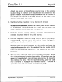
When using the recirculation kit (part no. 078-058),
fill a third of the
mix tank with a 50/50 antifreeze mix. Verify that the upper float is
not lying horizontal, but floats below.
Attach the recirculation fitting provided
in the kit to the garden hose quick
connect (see illustration to right) and
this combination to the front of the
machine.
I
HydraMaster
Corporation
-
I
12/12/96
CrossFire 4.2
Attach
one section
Page 4=3
of female/female
solution
hose to the outgoing
solution fitting on the front of the machine and the other end to the
garden hose and recirculation fitting combination that is attached to
the front of the machine (or as many sections as you want, if you
wish to freeze guard your hoses).
4,
Start the machine and allow it to run for two (2) minutes.
With the recirculation kit, depress the freeze guard button and hold
for 30 seconds. Turn the machine OFF. Leave the antifreeze in the
system until the next time you use the equipment.
5.
With the machine running, depress the dump
override switch and hold for thirty (30) seconds.
solenoid
manual
6.
Remove the garden hose inlet fitting from the end of your garden
hose and plug it into the front of the machine.
Leave it plugged in
until the next time the machine is used.
With the hoses and wand connected, run the machine and spray the
water/antifreeze solution out of the wand until the ‘low water’ switch
in the mix tank shuts the machine off. Your machine is now freezeprotected.
7.
Solution hose and wand freeze guard procedure (optional):
Attach
the solution hoses and wand to the machine.
(Dependent upon the
amount of hose attached, more antifreeze solution may be needed in
the chemical mix tank). With the machine running, spray the wand
into a container to recapture the antifreeze solution.
Continue to
spray the wand until the machine shuts down by itself.
HydraMaster
Corporation
12/12/96
.
CrossFire 4.2
Recovering
Page 4-4
antifreeze
for re-use:
Open the mix tank drain valve and allow the antifreeze solution
to drain into a sealable container so that it may be used again.
Before cleaning with the machine again, flush the remaining
antifreeze solution from the system by spraying water through
II
+ CAUTION
+
II
One manufacturer of antifreeze cautions: “WHEN DISPOSING OF USED
ANTIFREEZE COOLANT:
Follow local laws and regulations.
If required,
dispose
at facilities
licensed to accept household
hazardous
waste.
If
permitted, dispose in sanitary sewer systems. Do not discard into storm
sewers, septic systems, or onto the ground. ”
This warning appears on the label of one brand of antifreeze:
“HARMFUL
OR FATAL IF SWALLOWED.
Do not drink antifreeze coolant or solution.
If swallowed,
induce vomiting immediately.
Call a physician.
Contains
Ethylene Glycol which caused birth defects in animal studies.
Do not
store in open or unlabeled containers.
KEEP OUT OF REACH OF CHILDREN AND ANIMALS.
HydraMaster
Corporation
”
12/12/96
Water and
Chemical System
CrossFire 4.2
Section 5-1
T
his electro-mechanical
system
has been designed
to be simple and
trouble free.
WATER
AND CHEMICAL
FLOW OPERATION
Incoming water flows first through the Solenoid Control Valve and the low
pressure Chemical injector which are both mounted on the exterior of the
mix tank.
As the water passes through the Chemical injector, it is
automatically
proportioned with a predetermined quantity of detergent.
The Mix Tank is equipped with two different float switches, the Water
Level Float responds to the level in the tank and will maintain the proper
volume of solution to be reserved for the water pump. The secondary,
Low Water Float switch is a safety switch that is designed to protect your
system from sudden or unexpected loss of water supply. If, for example,
the water source at the house were turned off, the water level of the mix
tank would drop, activating the secondary switch, which automatically
disengages the system and prevents the water pump from running dry.
The desired chemical injection ratio may be obtained by an adjustment
of
the Chemical Flowmeter during the fill cycle of the mix tank. Water must
be flowing into the mix tank in order to adjust the chemical mix. The
chemical will flow from the Chemical Jug to the Chemical Flowmeter,
then to the Chemical injector where it is proportioned
at the desired chemical setting.
NOTE:
With
this
unique
chemical
system,
the
into the Mix Tank
chemical
flow
is
proportioned only during the filling cycles of the Mix Tank, not during the
HydraMaster
Corporation
4/5/95
“
Section 5-2
CrossFire 4.2
direct spraying of the wand. Therefore, it is possible that as your wand
is spraying, you may have no chemical flow. Also, the converse is true
in that you may not be spraying your wand, but if the mix tank is in a
filling cycle, your Chemical Flowmeter may be active at the desired flow
rate.
The chemical proportioning system will mix chemical with water at a 1 to
30 ratio when the Flowmeter is set at 5 GPH, or a 1 to 15 ratio when the
Flowmeter is set at 10 GPH.
CHEMICAL
SYSTEM
MAINTENANCE
The chemical lines may need to be flushed with vinegar periodically to
prevent abnormal chemical build-up.
This flushing may be done by
removing the clear plastic hose from the Chemical Jug and inserting it into
a one quart container of vinegar. This should be done with the Chemical
Flowmeter setting 10 GPH. Simply spray water from the wand until the
quart of vinegar is exhausted. Then repeat the process with one quart of
clear water to void all lines of vinegar.
HydraMaster
Corporation
4/5f”95
Page 5-3
CrossFire 4.2
Figure
D2926,
5-I
:
WATER
FLOW
DIAGRAM
Rev B
+
FROMWAND. _
_
1
K-
1
I
It
um-\
---rr
II
I
----
I
1
I
1
I
I
-.
I-------------~_---.
.
-----
.
-------
----
---------
I
I
.---,
II
-.
i
-1
I
-,
‘,% [
i----
‘--3
BLWERLU8E
1
~
I
I
.—
—1~
I
~
L
TCUPEPNURE
C..WCE l!-!
I
w
‘L-----
~
L-y
WP.4SS ml%
v-4
m=z~ G~D
,
~
O.c
“’yy
WARD (x,
FREEZE
COLOWA1’EFlIN
HI-W
WImul
I
L------
------
------------ I
+
---
;Al
~
1.!5+ ‘Am’0“’
COMUST OUT
HI-PRESSURE
LOWPRESSURE
❑WN
—
9
-Q
COM3WTION
ENGINE
wuM
+
F
8= BLOWER
Q
-Ep
$+
SOLENOIDVAM
NORWUY OPCN
MTH STRANER
HydraMaster
“WCiCHANOER
@ GNJGE
F!,.
+;:”:%,
SOLENOIDVW/E
NORMALLYCLOSED
W(THSrRAmm
RELIEFVALVE
VNM
ORIFICE
CENTRIFUGAL
PUMP
OWHRAW
PUMP
,+EF
--%-
ENGINECXHAIJSl
movm mwsl
— — — -
$nnIsmas
KTER,NC V#lE
CHECKvUE
G
lw.%5DucER
OR 5wWCH
++
Y-STRUNER
Corporation
8/15/97
Section 5-4
CrossFire 4.2
Figure 5-2: PROPORTIONER
DIAGRAM
n
6FA-6UFS
Mx Tank
-—
I
i
Injector Body
A
I
Check Valve
O-Ring
Chemical
Adjusting
Needle
t ,
I
Ill? e
3/8 Hex Nipple
k,
fl
!--1.
Cap
Nut
$)
1
1--1
I
$$i;-~d
,/
/
~~~~lenoid
-—
Mounting
Screws
(3)
—.
*
-
——
~
—
*
. .
12 VDC
Coil
HydraMaster
Corporation
Valve Bctdy
4
.—
.,.
..
Jr
— J
\
Water.
Inlet
J
Mounting
Plate
4/’5/95
Chemical Tank
Troubleshooting
CrossFire 4.2
Section 5-5
No
~:
Problem / Possible Cause
Solution
There is a loss of water
pressure.
1.1
There is a clogged fi/ter in the
water supply to the pump.
If a filter is present in the water
supply line to the pump, remove
and discard it.
1.2
The mix tank water supply hose is
missing. This will cause aeration
and turbulence in the tank.
Look inside the mix tank and
determine if a water inlet hose is
present.
If the hose is missing,
order a new hose from your
HydraMaster
distributor and install
it.
1.3
Foreign material is blocking the
outlet hole for the pump in the
bottom of the mix tank.
Inspect the outlet hole leading to
the pump in the bottom of the mix
tank. Remove any foreign material
blocking the hole.
1.4
Foreign material is blocking the
water supply hose leading to the
pump from the mix tank.
Remove the water supply hose
between the mix tank and the
pump. Sight through the hose.
Remove any foreign material from
the hose. Reattach the hose.
1.5
The water supply hose from the
mix tank to the pump is kinked or
blocked.
Remove the hose and clean it. If it
is kinked, order a replacement
hose
from your HydraMaster
distributor.
HydraMaster
Corporation
4/5/95
Section 5-6
CrossFire 4.2
No
Problem / Possible Cause
Solution
1.6
The end of the m{x tank water
supp/y hose is pointed directly at
the pump inlet hole in the bottom
of the mix tank.
inspect themix tank and determine
the orientation of the water hose.
If it is pointing directly at the pump
inlet hole in the bottom of the
tank, reposition the hose to point
towards the opposite side of the
tank from the inlet.
1.7
The mix tank supply hose is
blocking the outlet hole leading to
the pump in the bottom of the mix
tank.
The water inlet hose may have to
be shortened or lengthened to
avoid blocking the outlet hole.
1.8
There is an air leak in the water
supply hose from the mix tank to
the pump.
Inspect the supply hose for worn
or damaged areas. Also check for
loose fittings.
Replace the hose or
fittings if necessary.
1.9
The water supply hose from the
mix tank to the pump collapses
when the machine is running hot.
Allow the machine to reach full
water operating temperature
(approximately
10 minutes).
Inspect the water supply hose
between the mix tank and the
pump. [f the hose appears to be
collapsing, remove the hose and
order a replacement
hose from
your HydraMaster
distributor.
Reinstall the new hose.
NOTE: Older model machines will
require an additional 8M 12 UFS
fitting for the pump end of the
hose.
There is foreign
or outlet valves
Inspect the valves
foreign material.
1.10
HydraMaster
material in the inlet
of the pump.
Corpor@”on
and remove
any
1/25/96
CrossFire 4.2
Problem / Possible Cause
No
Section 5-7
Solution
1.11
The controlled orifice is loose and
water is flowing around it.
Clean the orifice and tighten the
fittings around it. This may require
adding an “O” ring around the jet.
Alsor check the fitting for wear.
If
there is excessive wear, replace
the fitting with part #052-025.
In the CrossFire 4.4 only, remove
the face mounted filter screen to
get to the orifice behind the filter.
Retighten the orifice with a 3/16“
Allen wrench.
NOTE: If your machine was built
before 10/1 2/95, update the
controlled orifice to the new style
orifice with part numbers 180-002,
052-423
and 052-013.
1.12
The by-pass valve is
malfunctioning.
Remove the plunger and lube the
“O” rings. Clean the walls of the
by-pass valve with a bristle brush
and de-scaler.
NOTE: Use a water resistant high
temperature
lube.
1.13
There is a loss of prime in the cells
of the pump because the oil level is
low.
Add oil to the pump reservoir.
Adjust the pressure regulator for
high pressure and run the pump for
20 to 30 minutes until it reprimes
itself.
HydraMaster
Corpor&”on
1/25/96
Section 5-8
CrossFire 4.2
Solution
Problem / Possible Cause
No
Inspect the water in the mix tank.
If there is oil in the water, a
diaphragm has ruptured.
Inspect
the oil level in the pump.
If there
is no oil in the pump, a diaphragm
For older model
has ruptured.
pumps, a new cushion plate should
also be installed.
Contact your
HydraMaster
distributor to
determine if you machine requires
a cushion plate. Order a
diaphragm replacement
kit from
your HydraMaster
distributor.
Remove the pump.
Replace the
Refill and reinstall the
diaphragm.
pump. See your owner’s manual
for the procedure.
1.14
There is a broken or cracked
diaphragm in the pump.
1.15
The pump “O” rings are forced
of their grooves from overpressurization
(freezing).
1.16
The pump manifold is warped
over-pressurizing
the system
(freezing).
1.17
The valve spring retainers in the
valve manifold are loose. (Retainers
should fit snug. )
HydraMaster
Corporation
out
from
Inspect the “O” rings. Replace
them if necessary.
See your
owner’s manual for the procedure.
Inspect the manifold with a
straight edge. Replace it if
necessary.
Install a valve
kit.
1/25/96
I
Section 5-9
CrossFire 4.2
2
Solution
Problem / Possible Cause
No
The water
low.
temperature
is too
2.1
The water dump (system
solenoid is stuck open.
2.2
The orifice (spray nozzle) in the
cleaning tool is worn, defective,
the wrong size.
Remove the electrical wires from
the solenoid.
If the solenoid
continues to dump, disassemble
and check for residue.
Clean and
replace the solenoid.
control)
or
Replace or change the orifice size.
The CrossFire uses a 8006E T-jet.
2.3
The incoming water
extremely cold.
supply is
Keep the incoming water supply
hoses away from ice and snow
during winter months.
2.4
There
is an exhaust
leak.
Inspect the exhaust system for
leaks. Tighten any loose clamp
welds or replace any broken parts.
2.5
There
is excessive
2.6
There
is exhaust
2.7
The 1850 dump sensor is shorted
or is operating prematurely.
Test the sensor.
necessary.
2.8
In the CrossFire 4.4 only, the
adjustable temperature
control dial
is set too low or malfunctioning.
If returning the temperature
control
dial to maximum does not work,
check the water temperature
in the
mix tank. At maximum the system
control light should come on at
approximately
187° - 190°.
If
not, replace the temperature
control unit.
2.9
In the CrossFire 4.4 only, the
temperature
control knob is turned
to “On”.
Turn the temperature
“off”.
HydraMaster
Corporation
pressure.
-
wrap missing.
Adjust the pressure
less pressure.
Replace any missing
regulator
for
wrap.
Replace
it if
knob to
1/25/96
Section 5-10
CrossFire 4.2
Problem / Possible Cause
No
2.10
lnthe CrossFire4.4
preheating system
malfunctioning.
only, the
is
With a test light, determine which
incoming solenoid is being
activated (EV-I or EV-2).
If EV-1
is being activated and the outgoing
water temperature
is below 235°,
check relay CR-3 and switch SW6. The coil on CR-3 should not be
activated.
There should be a
continuum between post 30 and
87a. SW-6 should be open.
Repair or replace as necessary.
Reset the engine speed.
Refer to
the Engine Operation and
Maintenance
manual.
2.11
The engine
2.12
A heat exchanger
is scaled.
De-scale the heat exchanger or
remove it and take it to a radiator
shop to be boiled out.
2.13
A heat exchanger
is carbon-coated.
a. For a stainless steel heat
exchanger,
clean it with a one
inch wire brush and oven
cleaner.
b. For a copper tube heat
exchanger,
carefully unplug the
tubes by poking a small rod
through them.
Then take the
heat exchanger to a radiator
shop to be boiled out.
2.14
The temperature
unit is defective.
HydraMaster
speed is low.
Solution
Corporation
gauge
sending
Check the sending unit. The unit
and temperature
gauge must be
manufactured
by the same
company (ie. an Isspro gauge
works only with an Isspro sending
unit and an S&W gauge works only
with an S&W sending unit).
1/25/96
Section 5-11
CrossFire 4.2
F
Problem / Possible Cause
No
2.15
The temperature
defective.
HydraMaster
gauge
Corpor&”on
is
Solution
Place the end of a grounded wire
to terminal 9a on the Diagnostic
Center while watching the
temperature
gauge.
The ground
should make the needle on the
gauge read maximum temperature.
Replace the gauge if necessary.
1/25/96
Section 5-12
CrossFire 4.2
No
3
Problem / Possible Cause
The water
excessive.
temperature
Solution
is
3.1
The fi/ter in front of the controlled
orifice is clogged.
Inspect the filter.
necessary.
3.2
The controlled
Inspect the controlled
Clean it if necessary.
3.3
The dump solenoid (system
control) valve is not opening.
Short out the dump sensor.
If the
dump solenoid valve has 12 volts
across the terminals and does not
open, replace it.
3.4
The dump (system
is not working.
The sensor switch is normally
open. It closes its hidden contacts
at 185° F. Replace it if it is
necessary.
3.5
The engine
high.
3.6
The temperature
defective.
HydraMaster
orifice
is clogged.
control)
sensor
speed is too low or too
Corporation
gauge
is
Clean it if
orifice.
Reset the engine speed.
Refer
the Engine Operation and
Maintenance
manual.
to
Place the end of a grounded wire
to terminal 9a on the diagnostic
center terminal block while
watching the temperature
gauge.
The gauge should read maximum
temperature.
If it does not, replace
the gauge,
1/25/96
Section 5-13
CrossFire 4.2
4
Solution
Problem I Possible Cause
No
There is pressure on the
gauge, but no water coming
out of the wand.
4.1
The wand jet is plugged.
Inspect
4.2
The quick connect on one or more
of the high pressure hoses is
defective.
Remove and clean or replace
defective quick connect(s).
4.3
The cleaning
valve.
Remove the valve stem.
Clean the
valve.
Replace the “O” rings and
stem if they are bad.
4.4
The high pressure quick connect
on the front of the machine is
clogged.
Remove and clean or replace
quick connect.
4.5
The inner lining on a hose is
constricted.
Remove the restriction
the hose.
tool has a clogged
and clean the jet.
the
the
or replace
,,,i
,.:;
.,’,
.,
HydraMaster
Corporation
1/25/96
Section 5-14
CrossFire 42
●
No
5
Problem / Possible Cause
Solution
The water in the mix tank
will rmt keep up with the
wand.
There is dirt in the solenoid
along side of the mix tank.
5.2
The upper float is bad.
Remove the wire on terminal 17b
at the Diagnostic Center.
With a
volt-OHM
meter check for
continuity from the end of the wire
you removed and terminal 20 on
the Diagnostic Center.
There
should be no continuity reading on
the meter with the float in the
down position.
Replace the float if
necessary.
5.3
The mix tank relay is bad.
With the upper float in the mix
tank in the up position, there
should be no voltage reading on
terminal 16 at the Diagnostic
Center.
With the float in the down
position, there should be +12
volts on terminal 16. Replace the
relay if it is defective.
5.4
The water supply
adjusted.
5.5
The water inlet supply hose filter is
clogged or the hose is kinked.
Remove the obstructions.
5.6
There is a problem
in pump.
Check the amount of water the
pump-in pump is supplying.
It
should supply a minimum of 2
GPM if you use one wand or one
RX20.
It should supply a minimum
of 3 GPM if you use two wands.
HydraMaster
Corpor&”on
valve
Take the valve apart and clean it.
5.1
is improperly
with the pump-
. The water supply should be two
(2) gallons per minute or more.
1/25/96
Section 5-15
CrossFire 4.2
No
6
Problem / Possible Cause
I
I
Solution
There is water coming out of
the exhaust.
6.1
There are small amounts of water
usually seen at start up.
This is norms/!
There is no
solution!
The water is
condensation.
6.2
One of the heat exchangers is
damaged from frozen water.
Determine which heat exchanger
bad. Replace it if it is necessary.
6.3
The recovery
Empty the tank.
6.4
There is excessive
recovery tank.
HydraMaster
tank is full.
Corporation
foam in the
is
Apply a powdered or liquid
defoamer to counteract
this
reaction to the excessive chemical
in the car~et.
1/25/96
Section 5-16
CrossFire 4.2
Problem / Possible Cause
No
7
Solution
The mix tank overflows.
7.1
The upper float in the mix tank is
malfunctioning.
With water in the mix tank,
connect one end of’ a 12 inch piece
of wire to terminal 20 (see the
Diagnostic Center) and touch the
other end to terminal 17. If the
water stops flowing with the key
on, replace the float.
7.2
There is dirt in the so/enoid
next to the mix tank.
Remove one of the wires from
terminal 16 (see the Diagnostic
Center) and turn the key on. If the
water continues to flow, then take
the solenoid apart and remove the
foreign matter.
Replace the
solenoid valve if necessary.
7.3
The chemica/ re/ay is bad or, in the
CrossFire 4.4 only, the CR-2 re/ay.
valve
Check the relay with a volt-OHM
meter. With the ignition key
turned on, there should be 12 volts
between pin 85 and 86. If the
voltage is present, check the
voltage between ground and pin
87a on the relay. If voltage is
present at 87a, replace the relay.
.
HydraMaster
Corporation
1/25/96
Section 5-17
CrossFire 4.2
8
Solution
Problem / Possible Cause
No
The water
pump is pulsing.
8.1
The hoses are restricted due to
hard water deposits andlor
chemical build-up.
Descale
8.2
The throb hose is hardened due to
age or heat and cannot absorb
spikes.
Replace the throb
8.3
The iniet hose is drawing
Reseal the fittings.
Tighten the
Or replace the hose.
hose clamps.
8.4
The valves are obstructed.
Clean or replace
8.5
There is a pin hole in one or more
of the diaphragms,
small enough to
lose the prime but not to leak any
oil into the water or water into the
oil.
Replace all of the diaphragms.
One could be replaced temporarily,
however all should be replaced.
8.6
The valve spring is broken.
Replace the valves.
HydraMaster
Corporation
air.
the machine.
hose.
the valves.
1/25/96
Pump Maintenance
CrossFire 4.2
Section 6-1
DAILY
Check the oil level and the condition of the oil. The oil level should be 3/4
inch from the top of the fill port to the line on the oil fill plug’s dipstick
(63).
Use a 5-30 weight
synthetic
motor.
If you are losing oil but don’t see any external leakage, or if the oil
becomes discolored and contaminated, one of the diaphragms (17) may
be damaged.
Refer to the Service Section.
Do not operate the pump with a damaged diaphragm!
ml
Do not leave contaminated oil in the pump housing or leave the housing
empty.
Remove contaminated oil as soon as discovered and replace it
with clean oil.
I
PERIODICALLY
Change the oil after the first 100 hours of operation, and every 400
When changing, remove the drain plug (60)
operating hours thereafter.
HydraMaster
Corporation
4/5/95
~
Section 6-2
CrossFire 4.2
at the bottom of the pump so all oil and accumulated
sediment
wii
drain
out.
-1
Do not turn the drive shaft while the oil reservoir is empty.
-1
Protect the pump from freezing.
I
HydraMaster
Corporation
4/5/95
Service of Wet End
CrossFire 4.2
Section 6-3
T
his
section
serviceabie
explains
to disassemble and inspect all easilyparts of the pump. Repair procedures for the hydraulic
end (oil reservoir)
manual.
how
of the pump are included
+ CAUTION
in a later section
of the
+
Do not disassemble the hydraulic end unless you are a skilled mechanic.
For assistance, contact HydraMaster (206-775-7275)
or the distributor in
your area.
1 i Remove Manifold
I
(3) and Valve Plate (12)
a.
Remove ail eight bolts (1) around the manifold.
b.
Remove the manifold
c.
Inspect the manifold for warping or wear around the inlet and outlet
ports. If wear is excessive, replace the manifold.
(3) and valve plate (1 2).
To check if the manifold is warped, remove the O-rings (4) and place
a straightedge across it. A warped manifold (.003 inches or greater)
should be replaced.
d.
Inspect the valve plate in the same manner as the manifold.
HydraMaster
———
————
Corporation
4/5/95
Section 6-4
CrossFire 4.2
2.
Inspect Valves (5-11)
The three inlet and three outlet valve assemblies are identical
Inspect each valve as follows:
the opposite direction).
a.
Check the spring retainer (1 O), and replace if worn.
b.
If it is shorter than
Check the valve spring (8).
replace it (don’t just stretch the old spring).
c.
Check the valve poppet (7).
If worn excessively,
(but face in
a new
spring,
replace it.
d, Remove the valve seat (6).
Inspect the valve seat for wear, and replace it if necessary.
O-ring (5) should be installed.
e.
Check the dampening
f.
Reinstall the valve assemblies:
b
Clean
A new
washer (1 1), and replace if worn.
the valve ports and shoulders
with
emery
lubricate them with lubricating gel or petroleum
P
Install the O-Ring (5) on the valve seat (6).
P
Inlet
(3 upper valves
in the illustration
below).
cloth,
and
jelly.
Insert
the
spring retainer (1 O) into the valve plate, then insert the spring,
valve,
Tetra
seal, valve seat,
and dampening
washer
b
HydraMaster
(8,7,9,6. 11). A flat O-Ring [Tetra seal] (5) goes between
retainer and seat.
the
Insert
the
Outlet
(3
Corporation
upper
valves
in
the
illustration).
4/5/95
.
Section 6-5
CrossFire 4.2
dampening washer, valve and spring, then the retainer.
the flat O-ring between the retainer and seat.
3.
Inspect and Replace Diaphragms
Install
(17)
a. Remove the two cap screws (14) from the valve plate (1 2).
b.
Lift a diaphragm
by one edge and turn the pump shaft
until the
diaphragm moves up to “top dead center. ” This
will expose
machined cross-holes in the plumber shaft behind the diaphragms.
c.
Insert a hex wrench through one of the machined cross holes, to
hold the diaphragm up. (Don’t remove the tool until the new
diaphragm is installed in step “g” below.)
d.
Unscrew the diaphragm.
counterclockwise.
e.
A ruptured diaphragm generally
Inspect the diaphragm carefully.
indicates a pumping system problem, and replacing only the
diaphragm will not solve the larger problem. Inspect the diaphragm
for the following:
E
Small Puncture.
Use a 5/16 in. open end wrench,
Usually caused by a sharp foreign
and turn
object
in
the fluid, or by an ice particle.
D
Diaphragm pulled away from the side.
being frozen
pump.
D
Diaphragm
in the pump,
becoming
caused by pumping
diaphragm material.
HydraMaster
Corporation
stiff
Usually caused by fluid
or by over-pressurization
and
losing
a fluid which
flexibility.
is incompatible
of the
Usually
with
the
4/5/95
.
Section 6-6
CrossFire 4.2
b
Diaphragm
edge
chewed
away.
Usually
caused
by over-
pressurizing the system.
f.
Clean away any spilled oil. Apply Loctite #242 Threadlocker to the
screw of the new diaphragm (or the old one, as appropriate).
9.
Install the diaphragm
and tighten to 10 in-lbs.
h.
Repeat
inspection
the
necessary)
4.
above
procedure
(and
replacement,
if
with the other two diaphragms.
Flush Contaminant
(only if a diaphragm
from Hydraulic End
has ruptured)
a.
With the valve plate, manifold, and diaphragm cushion plate still
removed (see above), remove the oil drain cap (63) and allow all oil
and contaminant to drain out.
b.
Fill the reservoir with kerosene or solvent.
Manually
turn the pump
shaft to circulated the kerosene. Drain.
-1
If you have EPDM diaphragms, or if food grade oil is in the reservoir,
do not use kerosene or solvents.
Instead, flush with the same
Pumps with EPDM diaphragms
lubricant that is in the reservoir.
have “E” as the 7th digit of the Model Number.
c.
Repeat the flushing procedure (step “B” above).
d.
Fill the reservoir with fresh oil. Manually
circulate the oil. And drain once again.
HydraMaster
Corporation
turn the pump shaft to
4/5/95
.
I
Section 6-7
CrossFire 4.2
e. Refill the reservoir.
in the reservoir.
clean.
I
5.
If the oil appears milky, there is still contaminate
Repeat the flushing procedure until the oil appears
Prime the Hydraulic
a. With
the pump
Cells
horizontal,
fill the reservoir
with
the appropriate
Hydra oil for the application.
I
b. All air in the oil within the hydraulic cell (behind the diaphragms)
must be forced out by turning the shaft (and thus pumping the
piston). A shaft rotator is included in the Wanner Tool Kit.
I
Turn the shaft until a bubble-free flow of oil comes from behind all
If it gets too
Watch the oil level in the reservoir.
the diaphragms.
low during priming, air will be drawn into the pistons (inside the
Hydraulic end). This will cause the pump to run rough, and you will
have to start over again with priming the hydraulic cells.
I
c.
6.
Wipe excess oil from the diaphragm plate and diaphragms.
Reinstall Valve Plate (12) and Manifold (3)
a.
Reinstall the valve plate (1 2), with the valve assemblies
outlined above, onto the diaphragm plate (18).
b.
Reinstall the O-rings (4) on the rear side of the manifold.
petroleum jelly or lubricating gel to hold them in place.
c.
Reinstall the manifold onto the valve plate.
d.
Insert all bolts (1) around the edge of the manifold, and alternately
tighten opposite bolts until all are secure. Torque to 15 ft-ibs.
HydraMaster
Corporation
installed as
Use
4/5}95
CrossFire 4.2
e.
Section 6-8
Recheck all bolts for tightness.
HydraMaster
Corporation
4/5/95
Service of
Hydraulic End
CrossFire 4.2
Section 6-9
T*
his section explains how to disassemble and inspect the hydraulic
(oii reservoir) of the pump.
end
PI
Do not disassemble the hydraulic end unless you are a skilled mechanic.
For assistance, contact HydraMaster (206-775-7275)
or the distributor in
your area.
Depending on the repair you are attempting, you may or may not have to
remove the motor from a direct-drive pump/motor unit.
Internal piston components (21 - 27) can be serviced without removing
the motor or crankshaft.
The motor and crankshaft must be removed to
service the connecting rod (59), piston housing (20), crankshaft (57),
front bearing (68), back bearing (55), or seal (54).
TO SERVICE PISTONS WITHOUT
1.
Disassemble
REMOVING
MOTOR
OR CRANKSHAFT
Pistons
With the manifold, valve plate, diaphragm cushion, diaphragm plate, and
diaphragm removed, and the oil drained from the pump (see the basic
Service Section):
a.
Remove the snap ring (27) from one of the pistons, using a standard
HydraMaster
Corporation
4/5/95
Section 6-10
CrossFire 4.2
snap-ring pliers.
b.
Pull out the valve plunger (24).
This also removes the washer
(26)
and spring (35).
c.
Insert a hook through the center hole of the valve cylinder (22), and
pull the cylinder out of the piston. Be careful not to damage the
piston.
d.
Inspect all parts, and replace the O-ring and any other parts which
are worn or may be damaged.
e,
2.
Repeat steps “a” through “d” for the remaining
Reassemble
pistons.
Pistons
a,
Tip the pump so the pistons are vertical.
b.
Drop a ball (21) into the opening in the bottom of the piston.
c.
Insert a valve plunger (24) into a valve cylinder (22).
(25) over the plunger, inside the valve cylinder.
Slide a spring
d. Slide the assembled valve cylinder, plunger, and spring (22-25)
into
the piston (20).
e.
Insert a washer
f.
Insert a snap ring (27) into the piston.
9,
Repeat the above procedure for the other two pistons.
HydraMaster
(26) over the plunger.
Corporation
Use the snap-ring
pliers.
4/5/95
“
Section 6-11
CrossFire 4.2
TO SERVICE
THE REMAINDER
OF THE HYDRAULIC
END
1. Remove Pump Housing
a.
Remove
the manifold,
valve plate, diaphragm
cushion,
diaphragms, as outlined in the basic Service Section.
b.
Drain the oil from the pump housing by removing
and
the drain plug
(60).
2.
c.
Stand the pump on end, with the drive shaft up.
d.
Remove the
housing (78).
e.
Remove the cover and the cover O-ring (53).
f.
Remove the crankshaft
rods (59).
bolts (50) that secure the back cover (52) to the
Use a 3/8 in. socket wrench.
Save the O-rings (51).
(57) by pulling it through
the connecting
Remove and Replace Pistons
To remove the pistons (20), first remove the connecting rod
and pin (58) by pressing the pin through the connecting rod.
59)
Reverse the process to reinstall the pistons.
Refer to Step 5 and
reassemble the pump.
3.
Reassemble
6
below
to
replace
the
diaphragm
and
Housing and Casting
NOTE:
Inspect the shaft seal (54) before continuing.
If it looks
damaged in any way, replace it. Refer to “Replace Shaft Seal”
HydraMaster
Corporation
4/5/95
.
Section 6-12
CrossFire 4.2
below.
a.
Stand the pump on end.
b. With the
crankshaft
c.
4.
pistons
and
connecting
rods
in place,
by threading it through the connecting
reinstall
the
rods.
Reinstall the back cover, cover O-ring, and bolts (with their O-rings).
Replace Shaft Seal
a.
Press the back bearing (55) and seal (54) out of the back cover (52).
Discard the seal.
Pipe Sealant with
b. Apply a coating to Loctite High-Performance
Teflon, or a comparable product, to the outer surface of a new seal
and the inside surface of the opening in the back cover (52) where
the seal will rest.
c.
Press the new seal into the back cover.
d.
Inspect the bearing (55).
e.
Apply
a
coating
of
If pitted or damaged,
Loctite
Rc-609
replace it.
retaining
Compound
or
comparable product to the outer surface of the bearing. Press the
bearing into the back cover until it rests on the shoulder. The shield
on the bearing must face away from the back cover.
5.
.
Reinstall Diaphragms
a.
Screw the plunger puller (from the Tool Kit or Repair Kit) into the
Pull out to expose the cross holes in the plunger.
plunger (24).
Rotate the shaft until the piston is at top dead center.
HydraMaster
Corporation
4/5/95’
Section 6-13
CrossFire 4.2
,.,
b.
Insert a diaphragm hex wrench (from the Tool Kit), or similar doweltype object, through the plunger holes to hold the plunger away
from the diaphragm place (1 8), and to keep the plunger from turning
when the diaphragm
c.
Apply
a small
diaphragm
is being installed.
amount
of Loctite
#242
to the
threads
screw (be sure the threads are clean).
d. Set the diaphragm (17) on the plunger (24), ridge-side
the diaphragm onto the plunger.
e.
of the
Hold the diaphragm
hex wrench,
out.
Screw
and tighten the diaphragm
to 10
Repeat the above procedure for the plungers and diaphragms
of the
in, -lbs of torque.
f.
other two cylinders.
9“ Fill the reservoir with fresh oil and prime the pump, as outlined
the basic Service Section.
6.
Reassemble
Pump
Reassemble
HydraMaster
in
the pump as outlined in the basic Service Section.
Corporation
4/5/95
I
Pump Troubleshooting
CrossFire 4.2
Section 6-14
Cavitation
Inadequate fluid supply because of:
-Inlet line collapsed or clogged
-Air leak in inlet line
-Worn or damaged inlet hose
Fluid too hot for inlet suction piping system.
Air entrained in fluid piping system.
Aeration and turbulence in supply tank.
Inlet suction vacuum too high.
Symptoms of Cavitation:
-Excessive pump valve noise
-Premature failure of spring or retainer (8, 10)
-Volume or pressure drop
-Rough-running pump.
Drop in Volume or Pressure
Air leak in suction piping.
Clogged suction line or suction strainer.
Suction line inlet above fluid level in tank.
Inadequate fluid supply.
Pump not operating at proper RPM.
Worn pump valve parts.
Foreign material in inlet or outlet valves.
Loss of oil prime in cells because of low oil level.
Ruptured diaphragm.
Cavitation.
Warped manifold from over-pressurized system.
O-rings forced out of their grooves from over-pressurization.
HydraMaster
Corporation
4/’5/95
Section 6-15
CrossFire 4.2
Air leak in suction line strainer or gasket.
Water
Pulsations
Foreign object lodged in pump valve.
Loss of prime in hydraulic cells because of low oil level.
Air in suction line.
Valve spring broken.
Cavitation.
Aeration or turbulence in supply tank.
Valve Wear
Normal wear.
Loss ~f Oil
External seepage.
Rupture of diaphragm.
Frozen pump.
Worn shaft seal.
Oil drain piping or fill cap loose.
Valve plate and manifold bolts loose.
Premature Failure of Valve Spring or Retainer
Cavitation.
Foreign object in the pump.
Pump running too fast.
Spring/retainer material incompatible
Excessive inlet pressure.
HydraMaster
Corporatkm
with fluid being pumped.
4/5/95
Section 6-16
CrossFire 4.2
DETAIL “A”
(Piston Assembly)
c)~
2
1
DETAIL “B”
(Valve Assemblies)
HydraMaster
Corporation
4/5/95
Section 6-17
CrossFire 4.2
PARTS LIST
REF. NO.
PART NO.
DESCRIPTION
QTY.
PER PUMP
D03-024-2010
Bolt, 3“hex-head
8
2
C22-01
Washerr
8
3
D03-004-I
4
D03-073-21
10
5
C24-009-21
10
6
D03-020-1002
Valve Seat,
7
D03-021
Valve,
1
4-2000
010
-1002
5/16”
Manifold,
O-ring,
1
brass, NPT
manifold,
O-ring, valve seat,
17-4
2
Buna
6
Buna
SST
6
17-7 SST
8
D03-022-31
14
Valve Spring,
9
D03-092-21
10
Tetra Seal, Buna
6
Elgiloy
6
6
10
D03-023-2310
Retainer,
11
D03-I
Washer,
12
D03-003-I
14
D03-029-2010
Cap Screw,
socket-head,
1”
2
16
DO3-O88-2O1O
Cap Screw,
socket-head
1/2”
2
17
D03-01
Diaphragm,
18
D03-002-1000
Diaphragm
19
D03-075-2110
O-ring,
20
D03-01
Piston
3
21
DIO-OI5-3O1O
Ball
3
22
D03-043-1
Valve Cylinder
3
23
D03-034-2110
O-ring, valve cylinder,
24
D03-044-1
Valve
25
26
27
D03-048-2210
HydraMaster
25-2310
010
8-1220
4-1004
000
Valve
valve spring,
dampening,
Celcon
Celcon
Plate, brass
6
1
Buns-N-XS
3
Plate
diaphragm
6
1
plate,
Buna
Buna
3
3
Plunger
3
D03-045-3110
Spring, sleeve valve
3
D03-049-I
Washer
3
Snap Ring
3
Corporation
000
000
4/5/95
CrossFire 4.2
HydraMaster
Corporation
Section 6=18
4/5/95
Section 6-19
CrossFire 4.2
PARTS LIST CONTINUED.
REF. NO.
PART NO.
50
D03-086-2010
..
DESCRIPTION
Cap Screw,
10
QTY.
hex-head,
with washer
PER PUMP
4
51
D03-036-21
52
D03-131-1000
Back Cover
53
D03-037-2110
O-ring,
54
D03-031
Seal, Buna
1
55
D03-01
Back Bearing
1
56
D03-085-221
Key, shaft
1
57
D03-009-1003
58
D03-I
33-1000
Pin
59
D03-I
32-1000
Connecting
63
000-027-006
64
DIO-080-21
68
D03-01
69
D03-087-201
70
D40-074-21
71
D03-I
78
D03-001
-2110
1-2910
O
O-ring,
back cover screws,
79
10
30-1000
-1001
1
RPM
1
3
Rod
Cap, HydraPump
O
Buna
shaft-driven,
3.0 GPM @ 1725
0-2910
4
1
back cover,
Crank Shaft,
10
Buna
3
w/ vent & O-ring
1
O-ring, oil fill, Buna
1
Front Bearing
1
Cap Screw,
hex-head,
O-ring, front cover,
1/2”
Buna
Front Cover
4
1
1
Pump Housing
[D-03,
M13-001-1001
Pump Housing
[M-1 3]
DI 0-040-2410
Name Plate
M-031
1
1
1
.
HydraMaster
Corporation
8/1/95
I
Cleaning Wand Parts
CrossFire 4.2
Section7-1
Figure 7-I:
VALVE
ASSEMBLY
‘1
HydraMaster
Corporation
10/31/96
Section 7-2
CrossFire 4.2
Figure 7-2: JET ASSEMBLY
18
17
.
HydraMaster
Corporation
4/5/95
Section 7-3
CrossFire 4.2
Figure 7-3: WAND
ASSEMBLY
21
27
22
Assembly
25
HydraMaster
Corporation
4/5/95
CrossFire 4.2
Valve,
ITEM NO
Page 7-4
Jet, Wand
Parts List
QTY
PART NO
DESCRIPTION
1
167-013
2
3
4
094-009
600-012-001
052-152
155-003
097-011
027-001
139-004
Trigger, Cast Hydra Hoe Valve
Nut, 1/4 -20 S/S Nylock
Valve Body - HydraMaster
Valve
1/4 Male Cornp. Fitting - Hydra Hoe
5
6
7
8
1
3
1
1
1
1
1
Spring, HydraMaster
Solution Valve
O-Ring, HMaster Solution Valve Cap
Cap, s/s HMaster Solution Valve
Ring, Solution Valve Retaining
9’
139-003
Ring Keeper,
10
097-010
O-Ring,
11
097-022
107-129
O-Ring, Solution Valve/Flowmeter
- small
Plunger, HydraMaster
Solution Valve
Valve Stem Sub Assembly (Incl. Items 8-12)
440 Male Quick Connect with Viton
Nipple, 1/4 Brass Hex
Elbow, 1/4 Brass 45 Street
Screw, 1/4 -20 x 1“ HHC s/s
Brass Stabilizer Housing
12
8-12
13
14
15
16
17
18
19
20
21
22
23
24
25
26
27
Not Shown:
600-012-002
052-050
052-071
052-082
143-002
052-153
186-001
076-005
094-028
061-006
094-035
143-012
173-001
082-004
168-001
061-007
154-001
169-055
143-005
094-009
052-151
081-015
174-003
174-065
HydraiWaster Corporation
HMaster
HM Valve
Solution
1
1
Valve
1
Plunger - Large
Stabilizer
Jet, #6 s/s Hydra Hoe
Nut, Brass - Jet Assembly Group
Handle, Pressure Guide Wand
Nut, 5/1 6-18
s/s Nylock Half Nut
Screw, 5/1 6-18
x 3/4” s/s HHC
Wand, s/s Hydra Hoe - Stock
Lips, 12“ s/s Hydra Hoe (2 piece set)
Tube, s/s Hydra Hoe Solution
Handle Grip - Hydra Hoe
Spacer, 1/4 x 5/16 - s/s Sol. Valve
Valve Assembly, s/s Hydra Hoe
Screw, 1/4 -20 x 1.75” HHC s/s
Nut 1/4 -20 S/S Nylock
Compression, %“ Female Hydra Hoe Fitting
Label, “Hydra-Manr’ - Wand
Washer, %” sls
Washer, .438” x 1” x .083” s/s
1
1
1
1
1
1
1
1
1
1
1
1
2
2
1
1
1
1
5
1
21
1
1
4
2
10/31/96
Vacuum System
CrossFire 4.2
Section 8-1
T
he vacuum
type.
blower
in this machine
is a positive
displacement
The performance and life of this unit is greatly dependent
care and proper maintenance
lobe
on the
it receives.
Because of the close tolerances between the lobes and housing of the
vacuum blower, solid objects entering the inlet will damage the internal
lobes, gears, bearings or drive system.
To prevent this, a stainless steel filter screen has been placed at the
vacuum inlet inside the vacuum recovery tank. This stainless steel screen
is finger tight and should be removed for cleaning weekly.
When machine is being run for test purposes and the vacuum
of the machine
inlet on top
is open, caution should be used.
To protect the vacuum blower from overloading and damaging itself, there
is a vacuum relief system installed on the vac tank. When the vacuum
tank inlet is completely sealed off, a maximum of 12 HG will be attained.
At the end of each day, an oil based lubricant should be sprayed into the
blower lubrication port before shutting down the machine.
If you fail to
lubricate the vacuum blower daily, rust deposits and moisture will
decrease the life of the vacuum blower.
HydraMaster
Corporation
4/5/95
.
Section 8-2
CrossFire 4.2
Foam
passing
through
Therefore,
it is important
Read the
vacuum
the
blower
could
lead
to
serious
problems.
to keep the vacuum tank foam free.
blower manual carefully for proper oil change and
The maintenance log may differ slightly from the
grease application.
manual, but the truck-mounted carpet cleaning machine application is very
demanding of the vacuum
more regularly.
blower and therefore
it should be maintained
The Vacuum tank is protected from overflowing by a vacuum tank float
kill switch.
The switch is not activated by foam, only by liquid.
VACUUM
TANK
HydraMaster
normally
FILTER BAGS
filter bags are designed to trap lint, sand and dirt that would
collect at the bottom of your vacuum tank.
The use of these
bags, if emptied at the end of each job, will eliminate the build-up of much
of the debris in the tank. The drawstring top of these bags is designed
to be slipped around the incoming dirty water inlet in the vacuum tank.
.
I
HydraMaster
Corporation
4/5/95
I
Blower Troubleshooting
CrossFire 4.2
Section 8-3
No
~
Solution
Problem / Possible Cause
There is. no vacuum
of vacuum.
or a loss
1.1
The stainless
1.2
The fi/ter bag is clogged.
Clean or replace the filter bag.
1.3
The vacuum tank dump valve k
“open” or defective.
If water drips from the valve when
the machine is not running, the
valve will cause a vacuum loss
when the machine is running.
Replace it if it is defective.
1.4
The hose on the live hose reels is
collecting water.
Unroll the entire length
each time you use it.
1.5
The vacuum
Remove the obstruction
by
reversing the vacuum hose.
1.6
There is a restriction
cleaning tool.
1.7
The vacuum
1.8
The hose from the blower to the
recovery tank is kinked or has
collapsed inside.
Replace or reshape the hose.
NOTE: A special reinforced hose is
required for replacement.
1.9
There
tank.
is a hole in the recovery
Inspect the tank for leaks using
smoke and weld the tank if it is
required.
1.10
There
hose.
is a hole in the vacuum
Repair or replace the hose.
1.11
The vacuum
1.12
The engine speed
HydraMaster
steel filter is clogged.
hose is plugged.
in the
tank seal is defective.
release
Corporation
is loose.
is too low.
Clean or replace the filter.
Remove
of the hose
the obstruction.
Replace the seal.
Readjust
the vacuum
release.
Adjust the speed.
4/5/95
Section 8-4
CrossFire 4.2
No
Problem / Possible Cause
1.13
The vacuum blower’s
lobes are worn.
1.14
There are vacuum
top collector box.
end plates or
leaks around the
Solution
Replace the worn components.
NOTE: This must be accomplished
by a qualified technician.
A vacuum leak can usually be
detected by spraying a mist of
WD40 or blowing smoke towards
the leak. The mist or smoke will
be sucked into the leak. When you
see the leak, repair it.
I
HydraMaster
Corporation
4/5/95
Section 8-5
CrossFire 4.2
Problem / Possible Cause
No
2“
The blower
Solution
is noisy.
2.1
There is an exhaust leak between
the blower and the silencer.
Inspect the fittings to determine
where the air leak is. Repair as
necessary.
2.2
The blower is out of oil or the
gears may be bad.
NOTE: Permanent damage may
result from a lack of lubrication.
Add oil. If the noise continues,
replace the gears or blower.
NOTE: Replacement
of the gears
must be accomplished
by a
qualified technician.
2.3
The si/enter
Inspect it for an external hole.
Repair or replace the silencer.
2.4
The lobes are hitting.
Replace the blower.
2.5
The engine is running at the wrong
speed. This is noticeable because
the blower noise increases with
speed.
Adjust the engine to run at the
proper speed.
2.6
The bearings
Remove and replace the bearings
as required.
NOTE: This process must be
accomplished
by a qualified
technician.
HydraMaster
is bad.
are worn.
Corporation
4/5/95
Section 8-6
CrossFire 4.2
3
Solution
Problem / Possible Cause
No
The Mower
will not turn.
3.1
The lobes
rust, burnt
sugar-like
vacuumed
3.2
There
3.3
The blower has broken gears or
shattered lobes.
HydraMaster
are locked up because
chemical foam, or a
substance has been
up from the carpet.
is debris in the b/ower.
Cqoration
of
a.
Most burnt foam and rusr can
be removed by soaking the
lobes with liquid wrench.
After
soaking the lobes, with the
machine running, pour a half
gallon of hot water into the top
of the blower.
Then spray
WD40 or Pennz Lube into the
top of the blower to displace
the water.
b. Any sugar-like substances
can
be removed by soaking the
lobes with hot water.
Remove the debris. A stainless
steel filter is provided at the
vacuum inlet in the vacuum tank to
prevent this problem.
Rebuild or replace the blower.
NOTE: Rebuilding the blower must
be accomplished
by a qualified
technician.
4/5/95
Section 8-7
CrossFire 4.2
No
4’
I
4.1
Problem / Possible Cause
Solution
turns, but the
;,tOtNi?S’ db HO*.
~liedmf~
The shaft
blower.
HydraMaster
is broken inside the
Corporation
Replace the blower.
I
4/5/95
Honda GX620 Engine
CrossFire 4.2
Section 9-1
1
154.5
1-
Figure 9-1
This information
HydraMaster
is taken from the Honda Ermines, Owner’s
Corporation
Manual.
4/5/95
Section 9-2
CrossFire 4.2
Figure 9-4
Figure 9-2
I
1
k=:=j-’---l”GX620
SPECIFICATIONS
Engine Type:
1-,24-25,2
Figure 9-3
(Page 31)
r’”’
’051
*
4-Stroke
Overhead Valve
2 Cylinders
(90° V-Twin)
Displacement:
37.5
cubic inches
(Bore x Stroke) 3.03
Maximum
Output:
in x 2.6 in
Torque:
,“3
A
Figure 9-5: GX620
--J
Performance
Curve
RPM
32.5 ft-lb
2,500 RPM
Engine Oil Capacity:
liters
(1.3 quarts)
1.2
t
Zocm
HydraMaster
m’
20 HP
3,600
Maximum
!---
Corporation
1
2xa
1
3DW
I
36(E3
4/5/95
Section 9-3
CrossFire 4.2
Fuel Consumption:
0.51
lb/hph
Cooling System:
Forced Air
BPR6ES (NGK)
w20EPR-U
(NIPPONDENSO)
Spark Plug:
Ignition System:
Transistorized
PTO Shaft Rotation:
Counterclockwise
PRE-OPERATION
Magneto
CHECK (Page 9)
Engine Oil
NOTICE:
Engine oil is a major factor affecting
engine performance
and
service life. Non-detergent oils and 2-stroke engine oils are
not recommended because they have inadequate lubricating
characteristics.
Check the oil level with the engine on a level surface and the
engine stopped.
Use Honda 4-stroke oil, or an equivalent high-detergent, premium quality
motor oil certified to meet or exceed US automobile manufacturer’s
Motor oils
requirements
for Service Classification SG, SF/CC, CD.
classified SG, SF/CC, CD will show this designation on the container.
SAE 10W-30 is recommended for general, all-temperature use.
Other viscosities may be used when the average temperature in your area
is within the indicated range. In the Honda Enaines, Owner’s Manual see
the chart on page 9.
1.
Place the engine on a level surface.
HydraMaster
Corporation
4/5/95
Section 9-4
CrossFire 4.2
2.
3.
4,
5.
Remove the dipstick and wipe it clean.
Fully insert the dipstick, then remove it to check the oil level.
If the oil level is near or below the lower limit mark on the dipstick,
remove the oil filler cap, and fill with the recommended oil to the
upper limit mark.
Reinstall the dipstick and filler cap.
Refer to the illustration on page 9 of the Honda Enqines, Owner’s
Manual.
Fuel Recommendation
~
+ WARNING
●
●
●
+
in the area where the engine is refueled or where
gasoline is stored.
Do not overfill the fuel tank (there should be no
fuel in the filler neck). After refueling, make sure
the tank cap is closed properly and securely.
●
●
~
Gasoline is extremely flammable and is explosive
under certain conditions.
Refuel in a well-ventilated
area with the engine
stopped.
Do not smoke or allow flames or sparks
Be
careful not to spill fuel when refueling. Spilled fuel
If any fuel is spilled,
or fuel vapor may ignite.
make sure the area is dry before staring the engine.
Avoid repeated or prolonged contact with skin or
breathing of vapor.
KEEP OUT OF REACH OF CHILDREN.
Use gasoline with a pump octane rating of 86 or higher.
We recommend
unleaded gasoline because it produces fewer
engine and
spark plug deposits and extends exhaust system life.
Hydraiklaster Corporation
4/5/95
Section 9-5
CrossFire 4.2
Never use stale or contaminated
gasoline nor oil/gasoline
mixture.
Avoid
getting dirt, dust or water in the fuel tank.
Occasionally you may hear light “spark knock”
or “pinging” (metallic
rapping noise) while operating under heavy loads. This is no cause for
concern.
If spark knock or pinging occurs at a steady engine speed, under normal
load, change brands of gasoline. If spark knock or pinging persists, see
an authorized
NOTICE:
Honda engine dealer.
Running the engine with persistent spark knock or pinging can
cause engine damage.
Running the engine with persistent spark knock or pinging is misuse, and
the Distributor’s
misuse.
Limited
Warranty
does not cover
parts damaged
by
Oxygenated Fuels
Some conventional gasolines are being blended with alcohol or an ether
compound.
These gasolines are collectively referred to as oxygenated
fuels. To meet clean air standards, some areas of the United States and
Canada use oxygenated fuels to help reduce emissions.
If you use an oxygenated fuel, be sure it is unleaded
minimum octane rating requirement.
and meets
the
Some
Before using an oxygenated fuel, try to confirm the fuel’s contents.
states/provinces
require this information to be posted on the pump.
The following
ETHANOL
HydraMaster
are the EPA approved percentages
of oxygenates:
(ethyl or grain alcohol) 10?40by Volume
You may use gasoline containing up to 10?40 ethanol
Corporation
by
4/5/95
“
1
Section 9-6
CrossFire 4.2
volume.
Gasoline containing
ethanol
may be marketed
under the name “Gasohol”.
MTBE
METHANOL
(methyl tertiary butyl ether) 15940 by Volume
You may use gasoline containing up to 15%
volume.
MTBE by
(methyl or wood alcohol) 5% by Volume
You may use gasoline containing up to 5% methanol by
volume as long as it also contains co-solvents
and
corrosion inhibitors to protect the fuel system. Gasoline
containing more than 5?40 methanol by volume may
cause starting and/or performance problems. It may also
damage metal, rubber and plastic parts of your fuel
system.
If you notice any undesirable
operating
symptoms,
try another
service
station or switch to another brand or gasoline.
Fuel system damage or performance problems resulting from the use of
an oxygenated fuel containing more than the percentages of oxygenates
mentioned above are not covered under warranty.
NOTICE:
Oxygenated fuels can damage paint and plastic.
Be careful
not to spill fuel when filling your fuel tank. Damage caused by
spilled fuel is not covered under warranty.
Air Cleaner
Remove the wing bolt, air cleaner cover, and the foam element.
1.
2.
Inspect the air cleaner elements.
Clean or replace the elements if
necessary.
If the air cleaner elements need cleaning, follow the
procedure described in the Honda Enaines, Owner’s Manual, page
21.
Reinstall the air cleaner elements and air cleaner cover. Tighten the
3.
HydraMaster
Corporation
4/5/95
-
Section 9-7
CrossFire 4.2
wing bolt securely.
Do not allow dust, dirt or debris to enter the air cleaner body
NOTICE:
when servicing the air cleaner.
For exploded view of air cleaner,
Enqines, Owner’s Manual.
OPERATION
see illustration
on page 12 of Honda
(Page 17)
High Altitude Operation
At high altitude, the standard carburetor air-fuel mixture will be too rich.
Performance will decrease, and fuel consumption will increase.
A very
rich
mixture
contribute
will
also foul
the
spark
plug,
cause
hard
starting
and
to air pollution.
High altitude performance can be improved by installing a smaller diameter
main fuel jet in the carburetor and readjusting the pilot screw.
If you
always operate the engine at altitudes higher than 6,000 feet above sea
level, have your authorized Honda engine dealer perform these carburetor
modifications.
Even with
suitable
carburetor
jetting,
engine horsepower
will decrease
approximately 3.5% for each 300 meter (1,000 feet) increase in altitude.
The effect of altitude on horsepower will be greater than this if no
carburetor modification
reduce performance.
NOTICE:
When
Corporation
A reduction in engine horsepower
will
.
the carburetor
the air-fuel
Operation at
high altitude
to overheat
HydraMaster
is made.
is modified for high altitude
operation,
mixture will be too lean for low altitude use.
altitudes below 1,800 meters (6,000 feet), with
carburetor modifications, may cause the engine
and result in serious engine damage.
For low
4/5/95
Section 9-8
CrossFire 4.2
altitude use, reinstall the standard main fuel jet, and readjust
the pilot screw.
Oil Alert System (Applicable Models)
The Oil Alert system is designed to prevent engine damage caused by an
insufficient
amount
of oil in the crankcase.
Before the oil level in the
crankcase
can fall below a safe limit, the Oil Alert system will
automatically
stop the engine (the engine switch will remain in the ON
position).
If the engine stops and will not restart, check the engine oil level before
troubleshooting in other areas. (To check engine oil level, see page 9 of
the Honda Enqines, Owner’s
MAINTENANCE
Manual. )
(Page 19)
The purpose of the Maintenance Schedule is to keep the engine in the
Inspect and service as indicated in the
best operating condition.
Maintenance
Schedule on page 19 of the Honda Ermines, Owner’s
Manual.
Shut off the engine before performing any maintenance.
If the engine
must be operated, make sure the area is well-ventilated.
The exhaust
contains poisonous carbon monoxide gas; exposure can cause loss of
consciousness and may lead to death.
NOTICE:
HydraMaster
Use only genuine HONDA
parts or their equivalent
for
maintenance or repair. Replacement parts which are not of
equivalent quality may damage the engine.
Corporation
4/5/95
.
Section 9=9
CrossFire 4.2
Engine Oil Change
Drain
the oil while
draining
Manual).
the engine is warm to assure rapid and complete
(see illustration
on page 20 of the Honda
1.
Remove
2.
suitable container.
Re-tighten the drain bolt securely.
3.
the oil filler cap and drain bolt.
Enqines,
Owner’s
Drain the oil into a
Refill to the upper limit mark on the dipstick with the
recommended
oil. (See page 9 in Honda Ermines, Owner’s
Manual.) Tighten the oil filler cap securely.
Engine Oil Capacity:
1.2 liters (1.3 US quarts, 1.1 imperial quarts)
Please dispose of used motor oil in a manner that does not
harm the environment. Do not throw it in the trash, pour it on
NOTE:
the ground or down a drain.
Air Cleaner Service
A dirty air cleaner will restrict air flow to the carburetor.
To prevent
carburetor malfunction,
service the air cleaner regularly.
Service
frequently when operating the engine in extremely dusty areas.
more
-1
Never use gasoline or low flash point solvents for cleaning the air cleaner
element because a fire or explosion could result.
NOTICE:
1.
Never run the engine without the air cleaner.
Rapid engine
wear will result from contaminants,
such as dust and dirt,
being drawn into the engine.
Remove the wing bolt and remove the air cleaner cover.
HydraMaster
Corporation
4/5/95
.
I
Section 9-10
CrossFire 4.2
2.
Remove the two 5 mm screws from the air cleaner cover and
remove the paper element from the cover.
Remove the foam
element
3.
Foam
from the air cleaner body.
element:
thoroughly.
Clean
in warm,
soapy
Or, clean in non-flammable
water.
Rinse
and
dry
solvent and dry.
Dip the element in clean engine oil, then squeeze out all excess oil.
The engine
foam.
4.
Paper
will smoke when started if too much oil is left in the
element:
Tap the element
lightly several times
on a hard
surface to remove excess dirt, or blow compressed (not exceeding
2.1 kg/cm2 -30 PSI) air through the filter from the air cleaner cover
inside.
Never try to brush the dirt off; brushing will force dirt into
Replace the paper element if it is excessively dirty.
the fibers.
Replace the paper element and both gaskets.
5.
Reinstall the air cleaner elements.
NOTICE:
Tighten the wing bolt securely.
Do not allow dust, dirt and debris to enter the air cleaner body
when servicing the air cleaner.
See exploded view of air cleaner in Honda Enaines, Owner’s
21.
Manual,
page
Spark Plug Service
Recommended spark plug:
BPR6ES (NGK)
W20EPR-U
(NIPPONDENSO)
To ensure proper engine operation,
gapped and free of deposits.
HydraMaster
Corporation
the spark plug must
.
be properly
4/5/95
Section 9-11
CrossFire 4.2
1.
Remove the spark plug cap.
2.
Clean any dirt from around the spark plug base.
Use the wrench supplied to remove the spark plug.
3.
The muffler
becomes
very hot during operation and remains hot for a
while after stopping the engine. Be careful not to touch the muffler while
it is hot.
4.
5.
Visually inspect the spark plug. Discard it if the insulator is cracked
Clean the spark plug with a wire brush if it is to be
or chipped.
reused.
Measure the plug gap with a feeler gauge. Correct as necessary by
bending the side electrode.
The gap should be: 0.70-0.80
6.
7.
mm (0.028
-0.031
in)
Check that the spark plug washer is in good condition and thread
the spark plug in by hand to prevent cross-threading.
After the spark plug is seated, tighten with a spark plug wrench to
compress the washer.
.
If installing a new spark plug, tighten 1/2 turn after the spark
plug seats to compress the washer.
.
If reinstalling a used spark plug, tighten 1/8-1 /4 turn after the
spark plug seats to compress the washer.
NOTICE:
●
The spark plug must be securely tightened.
●
An improperly tightened
spark plug can become very hot and may cause engine damage.
Use only the recommended spark plug or equivalent.
A spark plug
which has an improper heat range may cause engine damage.
See spark plug illustrations
HydraMaster
Corporation
(Honda Engines, Owner’s
Manual,
p. 22, 23).
4/5/95
“
Section 9-12
CrossFire 4.2
Fuel Filter
1.
Remove the two 6 mm
Remove the control cover.
2.
Check the fuel filter for water accumulation or sediment.
water or sediment is found, reinstall the control cover.
3.
If the fuel filter
sediment,
is found
with
bolts from
excessive
TRANSPORTING
the engine
the
water
take the engine to your authorized
Check fuel filter illustrations
Keep
special
cover.
If no
accumulation
or
Honda engine dealer.
(Honda Enaines, Owner’s
/ STORAGE
control
Manual,
pg. 26).
(Page 28)
level to reduce the possibility
of fuel leakage
when
transporting. If the fuel tank is equipped with a valve, turn the fuel valve
to the CLOSED or OFF position.
ml
●
To avoid severe
transporting
a
When
burns or fire hazards,
let the engine
cool before
it or storing it indoors.
transporting
the
engine,
turn the fuel
position and keep the engine level to prevent
vapor or spilled fuel may ignite.
valve
to the
fuel spillage.
OFF
Fuel
,
HydraMaster
Coqxmation
4/5/95
CrossFire 4.2
Section 9-13
Storage Time
Recommended Service Procedure to
Prevent Hard Starting
Less than 1 month
No preparation required.
1 to 2 months
Fill with fresh gasoline and add gasoline
conditioner*.
2 months to 1 year
Fill with fresh gasoline and add gasoline
conditioner*.
Drain the carburetor
float
bowl.
1 year or more
*
Drain the fuel tank. Drain the
carburetor float bowl.
Use gasoline conditioners that are formulated to extend
storage life.
Contact your authorized Honda engine
dealer for gasoline conditioner recommendations.
Before storing the unit for an extended period:
1.
2.
Be sure the storage area is free of excessive
humidity
and dust.
Drain the fuel.
a.
Disconnect
into
b.
HydraMaster
the fuel line to the engine, and drain the fuel tank
an approved
gasoline
container.
If the
fuel
tank
is
equipped with a valve, turn the fuel valve to the OPEN or ON
position to enable draining.
After draining is completed,
reconnect the fuel line.
Remove the control cover (see page 26 in the Honda Enaines.
Owner’s Manual), loosen the carburetor drain screw, and drain
the carburetor into an approved gasoline container.
After
draining is completed, tighten the carburetor drain screw and
reinstall the control cover.
Corporation
4/5/95
-
Section 9-14
CrossFire 4.2
Gasoline is extremely flammable and is explosive under certain
conditions.
Do not smoke or allow flames or sparks in the area.
3.
4.
5.
6.
Change the engine oil (see page 20, Honda Enaines, Owner’s
Manual),
Remove the two spark plugs and pour about a tablespoon of clean
engine oil into the cylinders. Crank the engine several revolutions
to distribute the oil. Reinstall the spark plugs.
Remove the battery and store it in a cool, dry place.
once a month.
Cover the engine to keep out dust.
TROUBLESHOOTING
Recharge
it
(Page 30)
The engine will not start:
Are the battery cables securely connected and free of corrosion?
1,
Is the battery fully charged?
2.
Is the fuse good (if equipped with Honda engine switch)?
3.
Is the engine switch in the ON position?
4.
Is there enough oil in the engine?
5.
6.
7.
8.
Is the fuel valve ON (if fuel line is equipped with a valve)?
Is there fuel in the fuel tank?
IS fuel reaching the carburetor?
To check, loosen the drain screw with the fuel valve on.
I
If any fuel is spilled, make sure the area is dry before testing the spark
plug or starting the engine. Fuel vapor or spilled fuel may ignite.
HydraMaster
Corporation
4/5/95
CrossFire 4.2
9.
10.
Section 9-15
is there a spark at the spark plugs? (See illustration on page 30,
Honda Enclines Owner’s Manual.)
Remove both spark plug caps. Clean any dirt from around the
a.
b.
base of the spark plugs, then remove both spark plugs.
Install the spark plugs in the spark plug caps and ground the
c.
side electrodes to any engine ground.
Turn the engine switch on. Pull the recoil starter.
d.
are sparks at the electrode gaps of both spark plugs.
If there are no sparks, replace the spark plugs. If OK, reinstall
See if there
the spark plugs. Try to start the engine again according to the
instructions.
If the engine still does not start, take the engine to an authorized
Honda dealer.
.
HydraMaster
Corporation
4/5/95
Section 9-16
CrossFire 4.2
Figure 9-6: Internal
Wiring
Diagram
COMBINATION SWITCH
BAT
LO
~or
,—Gr
—-
T
{Gr) —
-i
—
Llr ~
(Grl
IJ--
20 A CHARGE COIL
—
II
w-
—
CHARGE
IAMP
(12V-’I .4 w -3.4
1
gg
1
l--.,._.i_LG,
25A
.
h
-m
#-
0
SA17ERY
T
(
REQULATOR/
RECWWR
I
HydraMaster
Corporation
I
T
4/5/95
Engine Troubleshooting
CrossFire 4.2
Section 9-17
~
Solution
Problem / Possible Cause
No
The. engine will not turn aver,.
1.1
The circuit breaker
panel has tripped.
1.2
There is a loose battery cable or
corroded battery terminals.
1.3
The battery
1.4
There
link.
1.5
There is a problem
soienoid.
1.6
The ignition
1.7
The vacuum
HydraMaster
is
on the control
switch
blower
Corporation
Clean and tighten the battery
terminal connections.
Recharge
dead.
is a problem
Press the reset button.
Inspect the
unit to determine the cause of the
tripped circuit breaker and correct
the problem.
or replace
the battery.
with the fuse
Check the link.
replace it.
with the starter’
With the ignition switch in the
“Start” position, check the
following on the solenoid.
Check
for +12 volts on: a. the small
terminal with the blue wire from
the ignition switch, b. the large
terminal with the cable from the
battery, and c. the large terminal
with the cable going to the starter.
If the voltage is present on the first
two checkpoints,
but not on the
large terminal going to the starter,
replace the solenoid.
is defective.
has seized.
If it is defective,
Test the switch for entering
voltage.
If there is voltage
entering, but no voltage exiting the
center post when the switch is
fully engaged, replace the switch.
Refer to The Blower,
Chapter
10.
4/5/95
.
—
CrossFire 429
Problem / Possible Cause
No
1.8
The starter
1.9
There
1.10
Section 9-18
motor
is an engine
Ls defective.
Remove the belt(s) from the
engine.
Check to see if the engine
will turn over manually.
Check
that the engine is grounded to the
minus side of the battery.
With
the ignition key in the start
position, check the starter motor
for +12 volts.
If all of the above
conditions are met and the starter
will not turn, replace it.
problem.
Refer to the engine operation and
maintenance
in your owner’s
manual or see the local Honda
engine repair facility.
The ground cable underneath the
motor has fallen or broken off.
HydraMaster
Corporation
Solution
Reattach
the cable.
1/25/96
Section 9-19
CrossFire 4.2
Solution
No
Problem / Possible Cause
2
The starter turns the englue
over; however the engine wilf
not stafi;
(There is no
spark+.)
there is a spark, see troubleshooting
problem number 3 on the following page for
possible fuel problems.
2,1
The recovery
Empty the tank.
2.2
The recovery tank fioat is causing
the engine to shut down.
Disconnect
unit starts,
switch.
2.3
The oil pressure switch is causing
the engine to shut down.
Check the engine oil level. If it is
at the proper level, then disconnect
the oil pressure switch.
If the unit
starts, then replace the oil pressure
switch.
NOTE: The CrossFire machines
with Honda engines built prior to
May 1994 should have kit #078087 (Oil Pressure By-pass).
2.4
The high temperature
switch is
causing the engine to shutdown.
Determine the cause of
overheating
before restarting the
unit. See Chapter 6, CrossFire
Water System, Problem 3.
2.5
The high temperature
switch is defective.
Disconnect the switch.
If the
engine starts, then test the switch.
The switch operates at 2450 F.
Replace it if necessary.
2.6
The engine
2.7
tank is full.
is malfunctioning.
A spark plug is faulty.
HydraMaster
shutdown
Corporation
+ Check
for
spark
at the
spark
plugs.
If
~~~~l~s~~o~~~~u~~~~~.~e
HO~eVer
if
the float switch.
If the
replace the defective
Refer to the Honda Engine
Maintenance
manual included
your owner’s manual.
in
Check for worn, fouled or
improperly gapped spark plugs.
Replace if necessary.
CAUTION:
Allow the engine to
cool completely before attempting
to remove the plugs.
4/5/95
CrossFire 4.2
No
2.8
Problem / Possible Cause
A spark plug wire is faulty.
HydraMaster
Corporation
Section 9-20
Solution
While the engine is turning over
with the starter, make a visual
check to identify any bad spark
plug wire. In a dark, well
ventilated garage start the engine
and look at the plug wires.
If there
is a break in the wire you will see
arcing or sparking at the damaged
area. If you notice arcing, replace
the wire.
4/5/95
section 9-21
CrossFire 42
●
Solution
No
Problem / Possible Cause
3
The starter turns the engine
over, however the engine wilk
not start, (There is. no gas+. )
● Check for spark at the spark plugs.
If
there is no spark, see troubleshooting
problem number 2 on the previous page.
3.1
The chemical mix tank is out of
water caused by a defective upper
float in the mix tank.
When the float is down, the circuit
is open. When the float is up, the
circuit is closed.
Replace the float
if it is defective.
3.2
The chemical mix tank is out of
water caused by a dirty or
defective solenoid valve along side
of the mix tank.
The solenoid valve is normally
closed and should open with 12
volts across its terminals.
Remove
any foreign matter from inside the
valve.
Replace the valve if it is
defective.
3.3
The chemical mix tank is out of
water caused by a defective
chemical relay.
At the Diagnostic Center remove
the wire going to terminal 17a.
Turn the ignition switch on and
check for + 12 volts on terminal
16. If no voltage is present,
replace the chemical relay.
3.4
The tower float in the chemical mix
tank, which also activates the fuel
solenoid at the carburetor, is
defective.
Push in the freeze guard switch
located on the lower control panel.
(This is recommended
because it is
possible for the float switch to
carry enough continuity to light a
test probe but not enough to open
the solenoid. ) If the engine starts
and runs with the switch engaged,
then replace the defective float.
3.5
The fuel pump
Remove the fuel line from the
engine and place it in a container
to see if the fuel is being pumped
when the ignition is on. Replace
the fuel pump if it is defective.
3.6
There is a poor battery
the fuel pump.
HydraMaster
is defective.
Corporation
ground
to
if there is a spark, examine the
HOWeVer
above troubleshooting
guide for possible
fuel problems.
Repair the loose ground
connection.
4/5/95
Section 9-22
CrossFire 4.2
Solution
No
Problem / Possible Cause
3.7
The fuel pump is sucking air
between the gas tank and the inlet
side of the fuel pump.
Examine the gas inlet side of the
fuel pump. Tighten any loose
fittings or clamps.
Replace any
ruptured hose.
3.8
The fueJ filter is clogged.
Replace the filter.
3.9
The quick connect
is clogged.
Clean or replace
3.10
Vapor
3.11
The carburetor
defective.
HydraMaster
in the fuel line
the quick connect.
Move the fuel pump to a cooler
area. A vapor lock is caused from
excessive heat.
lock.
solenoid
Corpor&”on
is
Check for 12 volts at the solenoid
valve.
If the solenoid valve is not
opening with 12 volts going to it,
the valve must be replaced.
4/5/95
Section 9-23
CrossFire 4.2
4
Solution
Problem / Possible Cause
No
The engine runs poorly or
dies after running fix a: white;
If the engine runs better when
depressing the freeze guard
switch, then replace the float.
4.1
The lower
bad.
4.2
The fuel pump
4.3
The air or gas fi/ter is clogged.
4.4
There is a poor battery
the fuel pump.
4.5
The fuel pump is sucking air
between the gas tank and the fuel
pump.
Inspect for air leaks between the
pump and the gas tank.
Repair or
replace any leaking components.
4.6
A clogged heat exchanger is
causing back pressure.
The engine
will spit gas from the carburetor
and run slow.
Remove the hose from the blower
silencer to the copper heat
exchanger.
If the engine runs
better then remove the copper heat
exchanger and clean the debris
from it. If the engine still runs
badly then remove the brass plugs
from the top of the stainless steel
heat exchangers.
If the engine
runs better then clean the debris
from the copper heat exchanger
that is attached to the stainless
steel exchangers.
4.7
There is excessive
Clean and adjust the recovery tank
relief valve.
Adjust for 12 inches
of lift under a full load.
HydraMaster
float in the mix tank is
Remove the fuel line from the
engine and place it in a container
to see if the fuel is being pumped
when the ignition is turned on.
Replace the pump if it is defective.
is defective.
Corporation
ground
engine load.
Inspect both filters and replace
clogged one.
to
the
Inspect the electrical grounds.
Repair any loose wires.
4/5/95
Section 9-24
CrossFire 4.2
Problem / Possible Cause
No
Remove any air restriction from
around the engine.
Add a roof
vent or external fan, if necessary.
4.8
The engine overheats
ventilation.
4.9
The engine overheats from carbon
build up in the combustion
chamber.
Refer to a local Honda
dealer.
4.10
The engine overheats from too
much oil in the crankcase.
Check the oil level and correct
necessary.
4.11
The carburetor
defective.
Check for 12 volts at the solenoid
valve.
If voltage is present the
valve should be open.
If the valve
is not opening with 12 volts going
to it, the valve must be replaced.
4.12
The engine
4.13
On dual tank Fords, the engine is
pulling through the ‘Tank
Switching
Valve’.
Do not try to pull gas from both
gas tanks.
4.14
The PCV valve is defective.
Remove and check the air cleaner
for oil saturation.
If it is saturated,
replace the PCV valve and air filter.
HydraMaster
from poor
Solution
solenoid
vaive k
is malfunctioning.
Coqxwation
engine
it if
Refer to the Engine Operation and
Maintenance
manual included in
your owner’s manual or your local
Honda engine dealer.
1/25/96
Electrical System
CrossFire 4.2
Section 10-1
T
he CrossFire electrical system has been specifically designed with the
Often the most difficult problem to trace is an
operator in mind.
electrical failure.
The CrossFire series of machines utilizes a wiring diagnostic
center which
allows the operator or mechanic to trace all the electrical circuits from the
front of the machine.
The entire electrical system operates on 12 volts DC which is provided
by
a battery. Battery levels are sustained by a 20 amp alternator inside the
engine.
NOTE: When a new battery is installed, check that it is properly charged
before installation
or damage to the charging regulator may occur.
REFERENCE TO WIRING
Description
Ref.
TB
MTR
DIAGRAMS
Terminal Block
Ref.
CB
D
Motor
VR
Description
Circuit Breaker
Diode
Voltage Regulator
P
Plug
J
Jack or Receptacle
v
Valve
CR
Relay
FS
Float Switch
Sw
Switch
PMP
B
Butt Connector
Ps
Power Supply
HI
Hour Meter
TI
Temperature
PI
Pressure Gauge
SOL
VI
Vacuum Gauge
TT
L
HydraMaster
Gauge
Pump
Solenoid
Temperature
Sender
Indicator Light or Light
Corporation
11/21/95
Section 10-2
CrossFire 4.2
Figure 10-I:
HONDA
Wiring
MIX TANK
- Cy&I.
— 07
86
cR-2
070
m
as
CHEMFXI.
Sol.wnll
v-1
30
I
(
-P
K-l
—
L&&.&c$w
FKUT SWcn
@-
TQJgEJApRE
n-l
I
SW!NE
HIGH TEMP.
STOP SWITCH
1
I
L0w9~
PR?ESIRE
(
W.5hml;u
CR-
1
I
HOUR
U“y:
o
EWNINOTOP
f!%Lo-l
30
870
8’
HONOA
ENGINE
MTR- 1
85
87-
u?%
y
‘wf&:mp
CR-3
$
CFW+GE
C!RCIJ7
2!R*
CNO
WCUUU TANK
HIGH WAIER
FLOAT 5%lTCH
CB-7,
V?&J&u
w-!
—@-@+-
—
(
I
Czi
I
Vmwlmf.w
-. —-p5
87.
(
7
--—-
-—
--
877
?1
1
-.
+1
I
~
Gtm
bXl
HydraMaster
f?
i-:.
‘
-’O_i
RELAY SCHEUA71C
am
& PUMP IN TANK (OPTIONM)
Corporation
12/7/95
Section 10-3
CrossFire 4.2
HONDA
CrossFire Diagnostic Center
MAIN CIRCUIT
BREAKER-RED
TEMP LIGHT-BRN/WHT
1!
ERN,AYHT-TEA3-4
CHARGING CIRCUIT
BREAxER-ELu
S-GRN
12
SiRN/WHT-SYSTEN
13
REO/WHT-OIL
14
oRG/’wHT-TB3-
START SWITCH - lGt? -ELK
vAcuuu
SWITCH
rm_4Y #86-ORCpMT
VAC TANK LIGHT-ORC/WHT
WHINE
FREEZE CUARO SWITCH-GRN
H1-rEMP
PuMP-IN
-13LU
swiTcH-SRN
PUMP-OUT
150
SWITCH-RED/WHT
?6
BLU/WHT-CHEMICAL
CHEMICAL RELAY ,#86-GRY
I7
GRY-HOr
1E
GRN/WHT-FUEL
SHUT OFF VALVE
GRN/WHT- MIX TANK LOW WATER FLOAT
6-CRN/WHT
MIX TANK FILL FLOAT SWITCH-WHT
TEMPERATuRE GAuGE “GND” -WHT
TEMPERATURE GAUGE “9 -ORG
SWITCH-ELK/WHT
,~
RECWERY TANK ‘CNO” -WHT
VACUUM RELAy #f17-wHT
H
SWITCH
1
$%70 -BLu/w14T
CHEMICAL REI-N
START SWITCH “Sr
CONTROL
PRESSURE
~
SOLENOID
WATER FILL FLOAT SWITCH
WHT-ENGINE
WHT-@AITERY
STOP RELAY #870
GROUND
I
RED/BLK-ENGINE
RED/BLK-ENGINE
START SWITCH “A@
-ELK
6%“r
5
-87
VACUUM RELAY
CR-1
NOTE:
wiring
HydraMaster
STOP RELAY ~30
srop rJIooE
The numbers
s%“r
D
-
s,
CHSNl&RELAY
above correspond
J’:s
m -07
ENGINE C]TI)~
to the circled
REL4Y
numbers
on the
diagram.
Corporation
1/4/96
Machine Maintenance
CrossFire 4.2
Section 11-1
o avoid costly repairs and down-time,
it is imperative to develop and
T practice good maintenance procedures from the beginning.
These
procedures fail into daily, weekly, monthly and quarterly increments, and
are outlined below.
competent
Important:
All recommended
maintenance must be performed
by
service personnel.
Record the date and machine hours on the maintenance
log.
We have provided a maintenance log for your convenience at the end of
Log
this section. The @ symbol means to see this General Maintenance
for specific maintenance intervals. Records of maintenance must be kept
and copies may be required to be furnished to HydraMaster
before the
warranty is honored. It is recommended that you affix a copy of the Log
on the vehicle door near your unit for convenience and to serve as a
maintenance
reminder.
OPERATIONAL
MAINTENANCE
DAILY
Check engine oil level.
Inspect garden hose screen. Clean as needed.
Visually inspect machine for loose wires, oil leaks, water leaks, etc.
Inspect recovery tank s/s filter and filter bag for tears, holes, etc.
Clean, repair or replace as needed.
Lubricate blower with an oil based lubricant through blower inlet.
HydraMaster
Corporation
6/28/95
CrossFire 4.2
Page 11-2
WEEKLY
One time change of oil and oil filter after first 20 hours of use.
One time check of the belt tensioning after first 25 hours of use.
Check oil level in blower.
Check high pressure pump oil. Add as necessary.
Check drive system screws. Tighten as needed.
Check pump drive belt for wear.
Check pump pulleys for wear.
Check high pressure water lines for wear or chafing.
Check
Check
Inspect
Inspect
all nuts and bolts. Tighten as needed.
“Y” filter. Clean as necessary.
orifice.
vacuum
relief valve.
Clean and lubricate as necessary.
Clean vacuum tank thoroughly with high pressure washer.
Check wiring for any chafing.
Flush water and chemical system with 50/50 white vinegar solution.
MONTHLY
Change engine oil.@
Check engine air cleaner. Clean foam element as necessary.
Remove pressure By-pass Valve piston plate. Grease plate. Reinstall.
Check water level in battery. Clean connections as needed.
Change oil filter every 2 months.0
Check the belt tensioning every 2 months.@
The single belt drive system tension is approx. 3/8” deflection with
8 to 9 Ibs of force, measured at midspan.
The dual belt system
tension is approx. 3/8” deflection with 4 to 5 Ibs of force per belt,
measured
HydraMaster
at midspan.
Corporation
9/13/96
.
CrossFire 4.2
Page 11-3
QUARTERLY
Check fuel lines for wear.
Clean and gap spark plugs.~
Grease blower bearing fittings.
Change oil in blower.0
Change oil in pump.~
DE-SCALING,
As Required
Scale deposits on the interior of the heating system can cause a
Deposits of this kind result from
noticeable loss in heating performance.
hard water deposits, excessive chemical use, improper chemicals, etc.
The frequency with which de-scaling procedures are required will vary.
If your area has particularly hard water or you see evidence of deposits
in the water system,
you may have to de-scale monthly.
de-scale your system, add an appropriate de-scaler chemical to your
mix tank. Circulate it through the heating system.
Let it stand.
Flush
and repeat as necessary. Clean ail screens and strainers, and check them
frequently following de-scaling.
NOTE: If you are using T.M. DeScaler through the flow meter, make sure
to run clean water through the flow meter after this procedure.
To
To de-scale using the recirculation kit, start with an empty mix tank. Fill
a third of the mix tank with T.M. DeScaler. Follow the recommendations
on the T.M. DeScaler label for proportions.
Verify that the upper float is not lying
horizontal, but floats below.
.
,
Attach the recirculation fitting provided in
the kit to the garden hose quick connect
right)
and
this
(see
illustration
to
I
HydraMaster
Corporation
.
t
12/12/96
CrossFire 4.2
combination
Page 11-4
to the front of the machine.
Attach one section of female/female
solution hose to the outgoing
solution fitting on the front of the machine and the other end to the
garden hose and recirculation fitting combination that is attached to the
front of the machine (or as many sections as you want, if you wish to descale your hoses).
Start the machine and allow it to run for three to five minutes.
Depress
the freeze guard button and hold for 30 seconds. Do not leave the T.M.
DeScaler solution in the system. Flush the system with clean water and
turn the machine OFF.
OVERALL
MACHINE
Maintaining
reasons:
MAINTENANCE
the original
appearance
of your unit is important
for two
1.
a big dollar investment for your cleaning business and
its appearance should reflect that fact.
A dirty machine is not
professional.
2.
Maintenance,
It represents
troubleshooting,
and
repair
is
much
easier
to
accomplish on a clean, well maintained unit. Regular cleaning of the
machine offers you an opportunity to visually inspect all facets of
the machine and spot potential problems before they occur.
.
HydraMaster
Corporation
12/12/’96
CrossFire 4.2
The following
frequency
maintenance
Page 11-5
is recommended
by the manufacturer
at the
indicated.
AFTER EACH JOB
Check recovery tank, stainless steel filter and filter bag as required.
DAILY
Wipe machine down thoroughly with a damp cloth.
Flush recovery tank out thoroughly.
Empty filter bag and inspect for rips, tears, etc. Replace as needed.
Remove, thoroughly clean and reinstall stainless steel filter screen in
recovery tank.
Inspect and clean vacuum slot on cleaning wand.
Check wand head for sharp edges that could tear carpet.
needed.
File down as
Clean wand to maintain original appearance.
Wipe down vacuum and high pressure hoses as needed.
Visually inspect hoses for cuts, etc.
WEEKLY
Wipe down entire unit as needed.
Apply good coat of auto wax to all painted surfaces inside and out, and
to control panel.
Thoroughly clean recovery tank using high pressure hot water (unit with
optional high pressure cleaning gun may be used for this).
Remove stainless steel filter in recovery tank and thoroughly clean,
removing all lint build-up. Inspect for damage and reinstall.
Remove filter bag. Thoroughly clean and reinstall. [f torn, replace.
HydraMaster
Corporation
12/12/96
.
CrossFire 4.2
Page 11-6
Empty chemical from chemical container. Wash out thoroughly to
remove any chemical build-up.
Inspect chemical feed line strainer and use 50% white vinegar/water
solution to remove any chemical build-up.
Thoroughly clean wand and inspect for clogged jet, debris in vacuum
slot and leaking fittings at valve.
Apply light coat of auto wax to wand.
Thoroughly clean vacuum and high pressure hoses including hose cuffs.
Inspect for wear or damage to hoses and quick connect fittings.
Inspect garden hose connect/adapter screen for debris. Remove and
clean thoroughly.
Inspect all lines for wear or abrasions that may cause possible leaks.
HydraMaster
Corporation
12/12/96
GENERAL
MAX
HRS
DAILY
MAINTENANCE
LOG
OIL RECOMMENDATIONS
SERVICE
8
ENGINE OIL check
BLOWER
40 weight non-detergent
8
GARDEN HOSE SCREEN clean
PUMP
5-30
8
MACHINE general inspection
ENGINE
30 weight motor oil
8
RECOVERY TANK FILTER BAG clean
8
BLOWER INLET spray with lubricant
WEEKLY
NOTE:
OIL change
25
BELTS check tension
25
BLOWER check oil level
25
PUMP OIL check
25
ORIVE SYSTEM tighten screws
25
BELTS & PULLEYS check for wear
25
HIGH PRESSURE LINES check for chafing
25
NUTS & BOLTS check tightness
with filter
25
“Y” FILTER check and clean
25
ORIFICE inspect
25
VACUUM
RELIEF VALVE inspect, clean, lube
25
VACUUM
TANK clean
25
WIRING check for chafing
25
CHEMICAL
synthetic
Overhead
increased
motor
valve engines
oil
canusemulti-viscosity
oil, but will experience
oil consumption.
DATE & HOURS
SERVICE
20
Break-in.
One time only.
Break-in.
One tima only.
SYSTEM flush with vinegar
MONTHLY
100
weight
SERVICE
ENGINE OIL change
100
ENGINE AIR CLEANER clean
100
100
200
200
BY-PASS VALVE greaae piston and o-rings
SATTERY WATER LEVELS check
OIL FILTER change
BELTS check tension
QUARTERLY
SERVICE
(3 MONTHS)
300
300
FUEL LINES check for wear
400
BLOWER grease bearing
400
13LOWER OIL change
400
PUMP OIL change
SPARK PLUGS clean and gap
For a detailed engine maintenance table, see page 79 in Honda’s
in Section 9 of your CrossFire 4.2 Owner’s Manual.
GX620
Owner’s
Manual
iocated
GML CF 4.2 (9-1 3-961
How to Order Parts
CrossFire 4.2
Section 12-1
T
o obtain a proper diagnosis of your malfunction,
replacement
manner:
WARRANTY
and to order warranty
parts, it is important that you proceed
in the following
PARTS ORDERS
1.
Call HydraMaster
2.
Give the Warranty/Service
representative the following information:
A. Your Company Name and Address
B. Equipment Model
C. Date of Purchase
D. Hours on the Unit
E. Unit Serial Number
F. Name of Person Authorized to Order Parts
G. Sales Representative from which Unit was Purchased
H. Description of Malfunction
1. High Pressure Gauge Readings with the Wand Turned On
and Off
3.
If warranty replacement parts are needed, please specify method of
HydraMaster will pay for ground UPS.
If you
shipment desired.
require replacement parts overnight they will be sent freight collect,
via:
4.
Warranty/Service
Department
at (206)
775-7275.
Air Freight, Air Mail, or Air Express.
Do not give malfunctioning parts to a HydraMaster sales or service
representative. All parts must be returned directly to HydraMaster,
freight prepaid.
HydraMaster
Corporation
4/5/95
.
Section 12-2
CrossFire 4.2
PARTS ORDERS
In
To expedite your parts needs, please call your sales representative.
most instances,
he either stocks or has access
to parts through
a regional
service
center.
If further
assistance
is needed,
contact
the
factory
and
your needs. If this becomes necessary, always indicate
method of shipment you desire, i.e. UPS, Blue Label, Air Freight,
Express, etc.
coordinate
HydraMaster
HydraMaster
the
Air
Parts Dept. Phone . . . . . . . . (206) 775-7276
Parts Dept. Toll Free Fax . . . . 1-800-426-4225
HydraMaster
has a $40 minimum on parts orders.
minimum will be charged a $15 expediting fee.
Orders
below
the
ONE FINAL NOTE
Any questions you have regarding- the warranty
program should be
directed to the Warranty/Service
Department personnel at HydraMaster
Corporation.
We shall always endeavor to be fair in our evaluation of your warranty
claim, and shall provide you with a complete analysis of our findings.
HydraMaster
workmanship
reimbursement
HydraMaster
warranty
covers
only
for the
periods
listed.
is specifically excluded.
Corporation
defective
Labor
materials
and/or
and/or
diagnostic
.
4/5/95
Warranty Information
CrossFire 4.2
section 13-1
To
avoid misunderstandings
which might occur between
machine
owners and manufacturer, we are listing causes of component failure
that specifically voids warranty coverage.
Such causes as listed beiow
shall constitute abuse or neglect.
BLOWER: Failure to lubricate impellers daily with an oil based lubricant.
Failure to lubricate bearings as recommended in blower manual.
Failure
to maintain proper oil levels in the blower. Failure to use the correct oil
Failure to
grade and viscosity as recommended
in blower manual.
properly maintain blower safeguard systems such as waste tank filter
screen, vacuum safety relief valve and waste tank automatic shut-off
system. Allowing foam to pass through blower.
HIGH
PRESSURE WATER
PUMP:
Failure to maintain proper oil level as
Failure to change oil in pump at
recommended
in pump manual.
recommended intervals. Failure to protect pump against freezing.
Failure
Failure to use water
to maintain pump protection shut-off system.
softener in hard water areas. Use of improper chemicals.
VAC TANK:
Failure to properly maintain filtering devices in tank.
Failure
to clean tank as recommended
by manufacturer.
Failure to maintain
vacuum safety release in tank lid. Use of improper chemicals.
CHEMICAL
PROPORTIONER:
Use of improper chemical.
Failure to use
water softener in hard water area. Operating machine without proper
chemical filter screen. Failure to protect against freezing.
CONTROL PANEL:
against freezing.
HydraMaster
Failure to protect flowmeter and water pressure gauge
Corporation
4/5/95
.
CrossFire 4.2
Page 13-2
~
~
I
I
VACUUM
freezing.
AND SOLUTION
HOSES:
Failure to protect
Failure to protect hoses against burns from
hoses against
engine/biower
exhaust.
Damage to hoses from being run over by vehicles.
Kinking or
Normal wear and
cracking from failure to store or unroll hoses correctly.
tear from everyday use.
CLEANING WAND:
abuse of wand.
WATER
HEATING
Failure to protect against freezing.
Over pressurization
(recommended maximum working pressure -800 PSI).
against freezing.
WARRANTY
SYSTEM:
Obvious physical
of the system
Failure to protect
PROCEDURE
coverage is available to you ONLY through HydraMaster
11015
47th Avenue W, Mukilteo, WA 98275.
When
Corporation,
warranty
parts are needed, write HydraMaster Warranty Dept. at the
Warranty
above address, or call the Warranty/Service Dept. at (425) 775-7275.
No
When calling, be sure to have machine
collect calls will be accepted.
information and serial number ready for the service representative.
Hours
of Warranty/Service
Dept. are 8:00 am to 5:00 pm Pacific Time.
IMPORTANT:
HydraMaster’s warranty policy provides replacement parts
without charge for thirty (30) days to customers maintaining current
account status. An invoice will be sent to the customer for the amount
The customer’s faulty parts must be returned for
of the parts sent.
evaluation prior to the expiration of the thirty (30) day period.
Upon
the customer
for the
warranty
approval,
a credit will be ksued
replacement parts invoice. Warranty disapproval or failure to return the
faulty parts within the thirty (30) day period allowed will result in the
customer being charged for the replacement parts sent.
HydraMaster
Corpor&”on
6/24/97
.
Accessories
CrossFire 4.2
Section 14-1
Genuine
Accessories
T
his section
of your Owners
HydraMaster
& Detergents
Manual
is devoted
to Accessories
and Detergents which we have found to be helpful and useful.
These products can enhance your cleaning and reduce your labor
costs!
HydraMaster
Machine accessories are the most innovative collection
Our patented RX-20 Rotary
available in the cleaning industry.
Extractors have changed the shape of steam cleaning.
Our hoses
and tanks are of the finest quality construction.
SafeClean
Detergents have been specially prepared,
not only to give
you exceptional cleaning, but also to optimize your truckmount’s
operation and reliability. Most detergents don ‘t work we// under the
high heat, high pressure conditions of truckmount use. SafeClean
will maintain your machines’s water pump and water heating
systems
at peak efficiency
and help ensure fewer breakdowns.
For more information, or to order Genuine
HydralLlasterAccessories and Detergents
Call your nearest authorized Hydraltlaster Distributor.
.
HydraMaster
Corporation
4/5/95
HYDRAMASTER
I
I
6323
204th
Street
SW,
Lynnwood,
Corporation
WA 98036
PRODUCT SUPPORT BULLETIN
TO:
All HydraMaster
Owners
Machine
RE:
Acid Rinse Products
Precautions
DATE:
8 Ott
PSB #:
93102
1993
As most of you are aware, there is increasing interest in a process of cleaning using
acid rinse products.
Sometimes known as “fibre rinse, ” these products have an acid
base and can cause problems for carpet cleaning equipment.
HydraMaster
Corporation,
in response to market demand, has recently introduced a
new SafeClean chemical called “ClearWater Rinse”. Extensive testing was conducted
during the design phase because this is an acid based product.
The testing showed
that the acid based solutions used in most rinse products is very aggressive
in
attacking water system components.
As a result of testing, special protestants
were
added to our “ClearWater
Rinse” to make it safe for commercial use.
HydraMaster
advises that if you are using, or considering
the use of, a “rinse”
product, that you first determine its compatibility with your equipment.
HydraMaster
does not warranty equipment against the use of unprotected
acid products.
“
,,IJ
HYDRAMASTER
6323
204th
Street
SW, Lynnwood,
Corporation
WA 98036
PRODUCT SUPPORT BULLETIN
TO:
All CrossFire Owners
RE: Over-Temperature
Situation
HydraMaster
is issuing this maintenance
heated water in CrossFires.
tip:
DATE:
31 May 1994
PSB #:
94051
A clogged
filter can cause excessively
CrossFire machines have a “Y” type filter located on the front, lower right corner of.
the machine.
It is behind the front panel’. in back of the pressurized water quickconnect.
This filter should periodically be cleaned!
If the filter becomes clogged, the pressurized water is restricted from circulation
through the heat exchangers and becomes extremely hot when the cleaning wand is
at rest.
Checking
and cleaning this filter should be part of your weekly
maintenance
schedule.
HYDRAMASTER
6323
204th
Street
SW,
Lynnwood,
Corporation
WA 98036
PRODUCT SUPPORT BULLETIN
TO:
All HydraMaster
Distributors
RE: Oil Pressure Switch
Wiring Change on CF 4.2
DATE:
9 Jun 1994
PSB #:
94061
HydraMaster
has changed the wiring on the CrossFire 4.2 to eliminate the need for the
The oil pressure switch is now wired to the engine kill
oil pressure by-pass switch.
re/ay. The vacuum tank float switch and the high temperature
kill switch also operate
the engine kill relay.
The system
operates
as follows:
When the key is turned to the run position, the “RUN” and the “vAc TANK” lights
will illuminate.
When the key is turned to the start position, the “VAC TANK”
light will stay on until the oil pressure is built up. If the key is returned to the
run position while the “VAC TANK” light is still on, the engine will not continue
to run.
Product Support Bulletin No. 94061 ...
New CrossFire
4.2 Wiring
Diagram
mm. Rfuv
l–
“1‘%-k
L
H
(5$-)
.
Page 2
I
HYDRAMASTER
6323 204th
Street
SW,
Lynnwood,
Corporation
WA 98036
PRODUCT SUPPORT BULLETIN
TO:
All HydraMaster
Distributors
RE: ’93 Dodge Vans
Location of Fuel Tanks
DATE:
14 Jun 1994
PSB #:
94062
It has come to our attention that the fuel tanks on 1993 and newer Dodge vans are
located directly against the floor of the van. Caution must be used when drilling any
holes through the floor. The attached illustration indicates the area in the rear of the
van where no screws may penetrate the floor.
Dodge van may need to check
Anyone who has installed flooring in a 1993 or newer
The fuel tanks are rotationally
to see that no damage was done to the fuel tank.
If any holes were made in the tank they can be easily
molded polyethylene
plastic.
sealed with a hot knife. Please do not use an open flame.
4—
—.—
A
I
32.00
I
6.00
+
48.00
—~
.—
HYDRAMASTER
6323
204th
Street
SW,
Lynnwood,
Corporation
WA 98036
PRODUCT SUPPORT BULLETIN
TO:
All 1993-94
Truck-Mounts
RE: Fuel Pumps
DATE:
1 Sep 1994
PSB #:
94091
k..
HydraMaster, has available three fuel pumps (Nos. 111-001,
111-045
and 1 I I -002).
These pumps have different flow rates and pressure capability.
[n order to determine
which pump is appropriate for a particular application it must be “sized”. Each engine
has a particular flow and pressure limitation.
The mounting location of the machine and the fuel pump can effect how much fuel
Therefore
sizing a pump is important.
The
flow and pressure the engine sees.
accompanying
chart shows the options available for each machine and fuel pump.
If you are not able to mount the fuei pump within the required ranges
shown below,
please call HydraMaster
Service for other mounting
options.
Standard Fi@ Pump’
3.2 Briggs and Stratton
Briggs and Stratton
4.2
111-001
Sauare
Honda
111-045
Round
Kawasaki
111-002
Round
4.2
4.7
Onan
tiii&,&d
‘hwt~llatitm
111-001
Suuare
3.7
;“
111-045
Round
Mount 12 to 32 inches
below the carburetor.
.
Mount 32 to 48 inches
below the carburetor.
Honda
Diagram
1-
_—
— .
.——
.——
——
RUN
L-1
(i3Lu) —
(RED) —
- ($%-)
1
19(SLU)
42(BUQ
68(BLK)
—
(BLK)
>
CHARGE
CB-2
MA3N
CB- 1
1
m
k
fqzIq
(RfD)
!-
I
I
72(BLK)
—16
(#D)
(:IU)
(::U)
~1
,
(~ Q
I
o
c)
0
I
DASH ASSEMBLY
D-2848
0
MID PANEL ASSEMBLY
O-2928
f
L-5
64(BU()
P1- 1
TEMPERATURE
——
.
——
PRESSURE
GAUGE
—-
{>
(
—
1“
-!
ILl
‘1--;‘6:‘==
u
II
—lJ{WHI}
41 (BRN~T)
._—
—— —
Y
———
,––4
~
I
25(BW)
33(Bu4)
—
30
u
L
I
I
1
36(GlW)
18(GRN/WHl)
87a
J
—
Q3K
—
19(SLU) - (Q7
L
43(oRc/wHT)
35(BLu/wHr)
-.97
I
11
T“J’’TKSEMBLY
45(RED/wHn
6
II
Jia
Y
P
16(Buq
,.
I
39(BRN/WH7)
VACUUM GAUGE
‘“-1
_—
——
—
GAUGE
CHEMICAl
RELAY
CR-2
50(WHT)
38(W)
55(WHT)
—13(wHq
(w7iTj8Lu)
NOT USEO
I
L_—— _——— _—
HydraMaster Coiporah”on
12/7/95
Figure 10-4:
Honda wiring
Diagram
SEE SHT.
/
———
/
__—
.—
I
I
J-9
CHEMICAL
SOLENOIO
v-1
I
o
I
P-9
(ELK)—<+
WX’f)
(REO)+
p-a J-.9
T
50(WHT) —
—
f
_—
——
HI-TEMP.
ENGINE STOP
52(vM7) ‘>
l-l--l=
1
I u~
Q
f!jfi
●
SW-5
I
I*--,–
I
I
I
– – –4’@~/w~ <
I
I
LOWER
O-2929
I
T
MIX TANK FILL
FS-2
I
I
.— ~ I
*
%=.:,-—---u
(moj<+ ;2(GRN/wTl
+X&)=
I
I
(w)
——
I
~.——
P-il’J-11
___
46(8LK)
i?ECOVERY
PANEL ASSEMBLY
/
g
%
P-13 +13
_——
——
I
~x
LOW WATER
k
— _-
I
~:
I
1
MIX T#14K ASSEMBLY
O-2685
I
—
_——
———
TANK ASSEMBLY
0-2820
f
—~
R
60(WN7)
I
14/2
:028::EMBLY
I
(OPTIONAL)
-
,r*-.+
1-
1
I
1
—
57(BRN/w7)
58(BRN)
1’
FuEL
v-3
SHUT
OFF VALVE
56(W?17)
61(WN71
Llzi’
(ERN)~(8RN)
B-4
‘1
—
CABLE
r
P-t8J-18
4
78(ERN/WNT) ~>—-
41 (~N/~
5
P-t9J-t9
79(BRN) ~>—
26(ERN) —
-
/
SYS$MMC:ROL
CHARGING COIL
(INTERNAL)
-
OIL FILTER
-
OIL;RESSURE
1’
APO FLOAT
FS-4
PPpj::4P
b--_-.—----—~—
SWITCH
PUMP IN TANK (OPnONAL)~
F==F=$=’’’RN-
(BLK) --+>=
46(BW) —
f--
(2
FUEL PuMP
PMP-4
HydraMaster Coqgorah”on
11/21/95