1
HYDRA
MASTER
CX)RPOHA~
Dear Customer,
Thank you fur selecting Hydra -Mast(r Corporation
ds your equi ‘I(<>nt
manufacturer.
Only quality materials
have been ir)(,)rporated to ensure reliable performance
and long lif.c.
Another benefit you receive as a Hydra-Master owner
will be to receive Product Support Bulletins and supplements to this manual.
Our manual program is to keep
YOU
abreas! of changes and/or modifications to your
equipment .
Again, thank you and we shall continue to do all
possible to ensure you remain a proud Hydra-Master
owner.
President
Hydra-Master
Corp.
a
2030964th
Ave. W.*Lynnwoo
d.WA
98036*(206)
775-7272
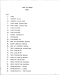
BOBCAT- HYDRACAT - DUAL CAT MANUAL
INI)EX
PAGE
1,
INDEX
lC a
PRODUCT SUPPORT BULLETIN
2,
WARRANTY
POLICY
2A,
WARRANTY
CLAIM FORMS
3.
PARTS ORDERS
4,
BOB CAT SPECIFICATIONS
4A,
HYDRA CA /DUAL CAT SPECIFICATIONS
It
II
It
H
tf
4B,
4C*
II
II
INDEX
INSTRUCTIONS
${
Ii
t!
5,
GENERAL
6,
MaintenanCe
6A,
MAINTENANCE
6B,
BOB CAT MAINTENANCE
6Co
HYDRA CAT/DUAL
7,
Bt-ONER LUBR~CAT~ON
8,
BOB CAT COMPONENT
8A,
HYDRA CAT/DUAL
9,
TRUCK PREPARATION
9A#
UNIT LOCATION
#l DRAWING
9B,
UNIT LOCATION
#2 DRAWING
9C,
TRUCK PREPARATION
9Dm
FLOOR GAS DIAGRAM
10*
OPERATING
111
BOB CAT/HYDRA
120
TROUBLESHOOTING
NFORMATION
LOG
DRAWING
CAT MAINTENANCE
DRAWING
DRAWING
DRAWING
CAT COMPONENT
DRAWING
DRAWING
PRECAtJTIONS
CAT/DUAL
CAT TROUBLESHOOTING
- ENGINE
PAGE
13,
TROUBLESHOOTING
- VACUUM/BLOWER
14,
TROUBLESHOOTING
- HIGH PRESSURE
15*
TROUBLESHOOTING
- HEATER
16,
TROUBLESHOOTING
- ELECTRICAL
17,
OVER-WETTING
18 s
FREEZING
PRODUCT SUPPORT BULLETINS
-
PUMP
SYSTEM
SEE PSB INDEX
19,
BOBCAT
20,
HYDRA-CAT/DUAL-CAT
21,
BOBCAT/HYDRA-CAT
HOSE DIAGRAM
22,
BOBCAT/HYDRA-CAT
FLOW DIAGRAM
23,
DUAL-CAT
24,
FLOW ADJUSTMENT
24A,
BOBCAT/HYDRA-CAT
25,
DUAL-CAT
26,
BOBCAT/HYDRA-CAT
27,
DUAL-CAT
28,
BOBCAT/HYDRA-CAT
29,
DUAL-CAT
30,
BOBCAT/HYDRA-CAT/DUAL-CAT
31,
PROPANE TANK PLUMBING
32,
BY-PASS
33,
INCOMING WATER REGULATOR
34*
HEATER CONTROL
35,
BOBCAT/HYDRA-CAT/DUAL-CAT
ELECTRIC PUMP CLUTCH ASSEMBLY
36,
BOBCAT/HYDRA-CAT/DUAL-CAT
PILOT LIGHT ASSEMBLY
37,
FUEL DIAGRAM
38,
BOBCAT
POWER PACK DIAGRAM
POWER PACK DIAGRAM
FLOW DIAGRAM
PROCEDURE
CHEMICAL
CHEMICAL
FLOW DIAGRAM
FLOW DIAGRAM
PLUMB ING (PUMP)
PLUMBING
(PUMP)
PLUMBING
PLUMBING
(HEATER)
(HEATER)
PROPANE TANK LOCATION
VALVE
EXHAUST
REGULATOR
HYDRA-CAT
.
OPERATION PROCEDURE
1
START-UP
PERFORM
DAILY/PERtOOIC
MAINTENANCE
AS SPECIFIED
2. ~i%?CT
ALL REOUlfdi’;O&ES.
NOTE: IMPORTANT
PURGE ALL AIR FROM INCOMING
TO liOOKllj & UP TQ MACHINE.
3. CONNECT CLEAtiltW
CLEANING.
BY ‘THE SERVICE
o
GARDEN HOSE PRIOR
T@2L TO LENGTH OF HOSE REQUIRED
if
T’(3 PERFORM
4. STAFW ENGI I? AT LdWTHROTTLE
AND ALLOW INITIAL WARM-UP PERIOD OF
TWO-FIVE M f
TES. (CHOKE AS REQUIRED).
NOTE: STEP r ‘5 THROUGH 9 SHOULD BE PERFORMED WITH CLEANING TOOL
ON.
5. ENGAGE
ELECTRIC
6. INCREASE
7.
.
CLUTCH
ON HIGH PRESSURE
IENGINE SPEED TO MAXIMUM
PUMP.
FACTORY
SETTING
(2400-2500
RPM].
OPEN CHEMICAL FLOW METER APPROXIMATELY
4 TO !5TURNS COUNTER
CLOCKWISE
FROM THE CLOSED POSITION
WITH CLEANING TOOL TURNED
ON, ADJUST INCOMING WATER REGULATOR AS REQUIRED TO ACHtEVE 9
GALLONS OF CHEMICAL FLOW PER HOUR. REOLICE CHEMICAL FLOW TO DESIRED SETTING (USUALLY 5 GALLONS/HOUR)
EY CLOSING (CLOCKWISE)
CHEMICAL FLOW METER VALVE.
“
NOTE: RECOMMENDED
PRESSUR~FC)R
CARPET CLEANING IS 30Q-4Q0 P S,1,
OUAL CAT CHEMICAL
ADJUSTMENT
— SEE tNSTRUCTIONS
BELOW.
8. LIGHT PILOT LIGHT ON HEATER.
NOTE: IF YOU SIJSPECT UNIT HAS FROZEN, DO NOT LIGHT HEATER ANO
REFER TO SERVICE BULLETIN NO. 112, OR CONTACT YOUR NEAREST
HYDRA-MASTER
REPRESENTATIVE,
$1. TURN ON HEATER BURNER ASSEMBLY AND ADJUST TEMPERATURE
TO DESIRED SETTING (130-200 F.].
NOTE: THE HEATER IS DEMAND OPERATED AND REQUIRES THE CLEANING
TEMPERATURE
SETTINGS.
TOOL TO BE TURNED ON To STABILIZE
1(3. COMMENCE
CLEAN(NG
OPERATION.
SHUT-DOWN
1. RETUFIN TOOL AND HOSES TO TRUCK
2. DISCONNECT
VACUUM
3. LOCK HYDRA-HOE
4.
“ON”,
OFF CHEMICAL
TURN
HOSE FROM TOOL.
FLOW.
!5. TURN HEATER TO OFF POSITION.
NOTE: WAIT UNIT ALL CHEMICAL
FREEZE
GUARDING
6. REDUCE
I
I
ENGINE
7. DISENGAGE
INJECT
9
TURN UNIT OFF
10,
STORE
UNIT
DO IT PRIOR TO STEP6.
SPEED TO SLOW SETTING
CLUTCH
LPS LUBRICANT
HOSES
Fflokf
FLUSHED
- IF NECESSARY,
ELECTRIC
8.
IS
INTO BLOWER
LUBE PORT FOR 78 SECONDS
PROPERLY
Water
Damage
— Vacuum
Only
START-UP
1
PERFORM
0NL%
STEPS
1, 2,
Ot-J[_Y
STEPS
3 AND
3, 4, (j+
AND
10
As
DESCRIBED
SHUT-DOWN
t
PER
FC)RtVl
7 AS
C)ESCRl
HE17
AOOVE
ABOVE
9
..
)
mfp,R=?
ccmPoan-
,.
0
~
MANUFACTURER’S
LIMITED WARRANTY
Hydra-Master
manufactured
Corporation
or supplied
-
extends to the original purchaser
of goods for use, the following
by Hydra-Master,
subject to fhe quallflcatlons
indicated.
Warranty
covering
goods
THEREIS NO OTHEREXPRESSEDWARRANTY
IN NO EVENTIS HYDRA-MASTERLIABLE
FOR INCIDENTAL OR CONSEQUENTIAL DAMAGES.
1 Hydra-Master
Corporation
warrants to orlglnal purchaser for the perlads set forth herein that goods manufactured
or
supplled by It will be free from defects In workmanshi~
and material, orovided such aoods are Installed, operated
and maintained
In accordance
with Hydra-Master’s
wr”lften instructions and that such ln~tallatlons are performed or inspected by Hydra-Master’s
Authorized
Representatives,
PRODUC1OR SYSTEM
CLEANINGUNIT
Engine
Vacuum/Blower
High Pressure Pump
Heater System
Frame
Instruments & Instrument
Hoses (Internal]
Cleaning Tools
Hose Reel(s]
Tanks
Fuel
Vacuum
HOSESAND FIITINGS (EXTERNAL]
Internal Controls & Valves
All Fittings (Internal)
Main Power Coupler (Eng. to Vacuum)
One Year or/1000
hours from date
of purchase.
Panel
High Pressure Hose
Vacuum Hose
Quick Connectors
or
Solutlon Couplers
Pulley Belts
Garden Hose
Three Months (90 Days)
from date of purchase,
Warranty expires
upon aftalnlng
either of the above
NOTE:The Ninety day limitation
on Warranty regarding
hoses and quick connect fltfings equals or
exceeds warranties extended by respective
manufacturers/suppliers,
sole liability and purchaser’s
sole remedy for a failure of goods under this Warranty and for any and all
other claims arising out of the purchase and use of the goods, Including negligence
on the part of the manufacturer,
shall be Iimlted to the repa Ir of the product by the repair or replacement,
at Hydra-Master’s
option, of parts that do not
conform to this Warranty,
Product or part(s) must be returned to Hydra-Master
Corporation,
20309- 64th Ave. W,, Lynnwood, Washington
98036, transportation
charges prepaid.
2. Hydra-Master’s
3. WARRANIV
reinstallation
DOES NOT INCLUDE: reimbursement
for labor, -travel time, mileage or work loss Incurred in the removal,
or replacement
of parts and/or equipment
approved
under the provisions of this Warranty.
4. THIS WARRANTY
A.
B.
C.
D.
E.
F,
G.
H,
I
SHALL
NOT APPLY
TO:
Cost of maintenance,
adjustments,
Installation and start-up.
Failures due to normal weor. accident, misuse, abuse, negligence
or improper installation.
Products which are altered or modified in manner not authorized
by Hydra-Master
Corporation
in writing.
Failure of goods caused by defects In the system or application
in which the product is installed, i.e. truck, van,
building, etc.
Telephone,
telegraph,
teletype or other communications
expense.
Living and travel expenses of persons performing
service excepting those authorized
by Hydra-Master
under prior
contract.
Rental equipment
used while Warranty repairs are being performed,
Overtime labor requested
by purchaser.
Parts, sub-assemblles,
assemblies
or major components
affected directly or indkectly by freezing,
IMPORTANT
Freeze Guard Systems incorporated
wlthln units either as standard equipment
or as options are convenience Items only. Hydra-Master
assumes no responsibility
for their failure, power failures affecting
thek performance or any resulting damage,
Items susceptible
a.
b,
c.
d.
e.
f,
to damage
by treezlng
are as follows:
Pressure & Solution Gauges
Flow Meters
High Pressure Pumps
Heater or heat exchanger
components
Hoses
Flttlngs [steel, brass and plastic]
g.
h,
i.
j.
k.
1,
Solutlon quick connect fittings (couplers)
Rellef valves or high pressure by-pass valves
Cleaning tools and their respective controls/valves
Regulators
and solenoids
Solution & pressure switches
Pump clutches damaged
by frozen pumps
5. No person
Is authorized
to extend any other warranties or to assume any other Ilability on Hydra-Master’s
behalf unless
made or assumed
In wrltlng by an officer of Hydra-Master
Corporation
and no person is authorized
to give any warranties or assume any other liabilities on behalt of seller unless made or assumed in writing by seller.
2
Claim No.
WARRANTY
CLAIM
DATE CLAIM FILED
Customer
Address —
City
State
Equipment
Model
Serial No.
Purchased
From
Date Purchased
No. of Hours Used
Briefly Describe
Defective
ziQ
Part
Defect
o
Signature
**+**********%********
***A.***A’+k*kk*k+** ****h**h***A**?t#t** ***A.****
Factory Use Only
Date Part Received
Describe
Inspected
By
Findings:
Actian Taken:
Amount
of Claim $
a
GENERAL
INFORMATION
This manual contains installation and operation
instructions as well as information required for proper maintenance, adjustment and repair of this unit.
Since the first and most important part of repair work
is the correct diagnosis of the trouble, a general
troubleshooting section and component manual troubleshooting charts have been included for your convenience.
Unlike
mixer all
form, the
plant has
the garden tractor, lawnmower and cement
having one and maybe two functions to perHydra-Master truck mounted carpet cleaning
many functions to perform simultaneously.
1. Engine has to run consistent RPM.
2. Vacuum has to pull air and dirty water back
from cleaning site.
3. Water pump provides stable pressure at proper
water flow for cleaning.
4. Chemical has to be injected into the water
stream at the right consistency.
5. Heater must fire on demand and maintain proper
(Except for Aqua Cat).
heat.
6. Vacuum tank must store dirty water until drained.
As you can see, it is not just a turn key operation
with only one thing to worry about, DOES IT START?!
As there is no guesswork in the manufacture of these
highly advanced cleaning plants, there must be none in
It is the
preparing it to get the job done in the field.
purpose of this manual to help you properly understand,
maintain and service your Hydra-Master cleaning plant.
Follow the directions carefully and you will be rewarded
with years of profitable trouble-free operation.
It is imperative that no section be overlooked
preparing for operation of this equipment.
=
.
when
WARNING
Hydra-Master uses this symbol
throughout the manual to warn
of possible injury or death.
CAUTION
This symbol is used to warn of
possible equipment damage.
5
MAINTAIN
GOOD PROFIT - WITH GOOD MAINTENANCE
In the past 3 years, we at Hydra-Master have become alarmed
increasing number of calls pertaining to service problems.
at the
Our findings are that 85% of all down time is a direc- result of poor
maintenance habits.
If maintenance is a difficult function to schedule
into your busy operation, here is one important parallel that may influence your thinking toward maintenance procedure:
Each hour of machine
operation
is equal to 75 miles of driving.
A 5% hour average day equals 310 miles.
An average
5 day week or 27+ hours = 2062.5 miles.
Each month an average of 8660 miles
One year of average machine
is put on the machine.
operation
is equal to 103,920 miles.
Compare this to your car and the maintenance
for this many miles of trouble-free driving!
you would give it
Enclosed is a maintenance log sheet that should be attached
machine and kept in force by a responsible operator.
GOOD PROFITS
AND GOOD MAINTENANCE
GO HAND IN HAND
HYDRA-MASTER
WANTS YOU TO BE A TROUBLE-FREE
DRIVER!
to the
a
HYDRA-MASTERCORPORATION
J
MAINTENANCELOG
DATE
MAX
HRS. HOURS
SERVICE ITEMS
DATE
DATE
DATE
DATE
DATE
HOURS
HOURS
HOURS
HOURS
HOURS
“
DATE ~
~
HOUR;‘
...
,.
e.,
*
**
Winter SAE 20) 3 Qts. W/O Oil
30
Filter, 3% Qts. W/O Filter
* DisassembleH/P Bypass Valve &
100
Lube Stem Assy. (Ref.Drawing)
Remove Machine fron Truck for
Complete Inspectionof:
100
Battery Electrolytes
100 I
Belts and Pulleys
Fuel Lines
100
Nuts and Bolts
100 I
Heater Cover (ExceptAqua-Cat)
100
Heater Burner Assy. (Ex. Aqua-Cat]1()()I
ServiceAir Cleaner
100
Clean Vacuum Tank (free float
hinge of lint & lube)
100
Spray Quick Connectors (all)
With WD 40
100
Lightly Oil Direct Drive Shafts
100
100
Check for ChafingWires
Tighten ExhaustManifold Clamps
100
TightenDodge Coupler (direct
drive) (DO NOT OVER-TORQUE)
100
Replace Engine Oil Filter
200
Replace Spark Plugs (LP gas
gap .018/gasagp .025)
200
* Change Blower Oil (40 wt. non200
L detergent)
R(eplace
Points & Condenser
(gap .020)
300
1
k
Zrease Blower Fittings
300
*
Change Pump Oil (Cat oil)
300
Lube ThrottleLever
300
Heater Slide & Button Assembly
300
Zheck Engine Valve Clearance&
Decarbon Heads
400
eplace Pump Short Cup Kit
I1OOO [
InspectValves (grindif net.)
I 1000 j
* Engine Oil * Blower Oil * Pump Oil
-
!
i
1
\
J
b
,
I
-1
I
—
-1
1
I
I
I
1
I
1
Summer 30 SAE
40 SAE Non-Detergent
Special Cat Oil
RecommendedFuel - Unleaded Gasoline
** Engine CrankcaseBreatherCleaning ! - Refer
to
Onan ServiceManual.
6A
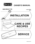
HTRUCK
Truck Prep. : Materials
Decide
location
needed:
of machine
M
1-79
PREPARATION
1. 6’ x 12’ Ozite indoorioutdoor carpet
(1 side good)
2. 4x8x5\8° pl~ood
14”
sheet
metal
screws
3. 6
4.
1 - l“x1’’x18” angle iron
bolts
5.
3 - 2“x5/’l6”
6.
3 - 5/16” flat washers
7.
3 - 5/16” lock washers
8.
3 - 5/16” nuts
9.
1 can marine adhesive
10. 1 staple hammer or glue gun
11. 1 gas hook-up (thru floor mount)
in Van.
This provides
Most installations are side door.
A. Side door:
rear access for accessories and hoses as well as unobstructed
access to component\working
side of machine~ thus making it a
bit easier to perform maintenance andior repair witihout removing
unit from the truck.
Although this location partly limits working access,
B. Rear door:
it does direct the noise away from the cleaning site. Some
cleaners in the colder areas prefer this location because it pu m
the weight mass over the rear-wheels for better traction in ice
Rear mounting requires the unit to be slid to the
and snow.
This not only provides adequate
right side as far as possible.
working space on the component side of the unit but also makes
better weight distribution inside the Van (engine and component
Also, it is physically easier to
Wt . line up over drive shaft).
load unit into rear door due to height of Van bed. When carrying
water, tank will then be located over center of Van.
IIEEl
Ensure that machine is well secured to the floor of Van with
Sudden or crash stop will cause machine to
hardware supplied.
Protect your driver and
rocket forward, all 550 lbs. worth!
machine.
SECURE IT!
‘,
I
I
‘------‘——-_--_--=\=-’
{,/
,
j
.’/’”
No.
....—
:
2
PART
DESCRIPTION
..—_
QTY
‘c@” o
@
611001 QUICK CONNECT SOCKET
612090 FITTING (1/8 EiRS.STR.
ELBOW)
625701 PLATE
619121 SCREW
613025 HOSE BARB
620104 HOSE CLAi%fP
637105 HOSE (CUTTO LENGTH)
625300 FUEL FILTER
612120 FITTING
620305 TIE WRAP,
625700 THW-FLR GAS HOOK-UP
(l-lo)
1
1
1
2
4
6
4
1
1
6
1
.NOTE:OR{LC
~“HOLE7HwU
THE
TRUCK
FLCOR
TO
RECEIVE
FITTliJG
AT
THE
LOCATION SHOWN.~
r.
1
)
o
11
.>
b
-d
‘
THRU-FLOOR
GAS
HOOK-UP
DRAWING NO
DRAWN BY
C9ATE /REV.
“HM-121
PAZ’
(9. GF?A1’4T.&?.
I -
6- s
gj-j
~
—
f
}
..... .. -..—
,
-
m
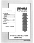
PROPANE
..—.-
TANK
~
●
LOCATION
~
w—
—
-+-
<ET PART
~1
NO
1
PART
..
DF%17RTPTTOL
-.
‘QT7
,
Jw—
PROPANETANK
~~702~ A. I(3Gal.
627022 B. 16.5 Gal.
‘627023
C. 23
1
‘AN E
)NIT
‘\
&-r&\,
Gal.
614002 SPUDNUT
3. 6~70(30PROP~E RE~U~TOR
1\ 614006
4.
PROPANEFITTING‘------”
e
1
1
1
2.
i M% RR:: :!%,
,i]:
7. 627005 PLATE (THRUFLOOR)
2:
8.
9.
10.
[1.
12.
13.
[4.
[5.
,6.
619121
610211
614009
637301
618620
616030
616231
617600
627004
SCREW
2
PROPANEFITTING
1
PROPANESHUT-OFFVALV 1
PROPANEHOSE
11
4
CARRIAGEBOLT
FLAT WASHER
8
LOCK WASHER
4
NUT
4
PROPANETHRU-FLOOR
1
HOOK-UP (Incl.parts
2-11)
I
\
4%?0fsANE TANK
oticiuld.be mmmtel
en the si8eofthe
truek?is
ALLOW
“’%lld
d$CCESS to &LL
tfie V&LVES.
-RELIEF
-PROPt3NE
A
VAL.V!E
REGULATOR
10%VALME
\’\lz7k
PROPANE VAPOR VALVE
TANK
\Y
FILL
VAIWE
uMB]N~
DATE
—.
6-13
-7!3
HYDRA/DUAL
CAT SPECIFICATIONS
GENERAL
Warrantiy
* One Year
or 1000 Hours
Dimensions
* 48” L X 32’r w x 34~f H
Weight
* 550 Lbs.
COMPONENTS
* 20 Horsepower
Onan
Industrial Air-cooled
A. Engine
RPM
* 2600 Factory
Fuel
* Unleaded
CJil Capacity
* 3J5 Quarts
B. Vacuum/Blower
W/Filter
* Positive Displacement
(Lobe Type)
* 2600 Factory
RPM
Water
Lift
& Air Flow
* 195-210
275 CFM
Grease
* High
Temperature
* Special
Pressure
* Hydra
Dual
Belt
Heat
Cat Oil Lubricant
Cat - 300 PSI
Pre-set
- 300 PSI
Cat
Pre-set
Factory
adjustment
Factory
adjustment
* 5L380
* 900
R.P.M.
D. Propane
Bearing
* Positive Displacement
Piston W/Stainless
Cylinders
Oil
Pulley
Pre-set
*
* 40 S.A.E.
Pump
Recommended
inches
Clil
C. Water
Recommended
Heater
Setting
* 120,090
BTU Temperatl]re
* 140 - 250 Max.
Fired
E. Frame
* Retractable
Legs
Recovery
.
* Steel
Construction
* Anodized
Tank
W/Castered
Wheels
Aluminum
F. Hoses
* Teflon
Sheath
Internal
W/Steel
Reinforced
External
Solution
* High Pressure - Non-Marking
2500 P.S.I. Rated
External
Vacuum
* Heavy Duty
Marking
Flexible
and Non-
G. TOOIS
Hydra
Hoe Carpet
Wand
* Stainless Steel W/Adjustable
Handle and High Pressure Valve
Jet Size 8008E - Hydra Cat
8006E - Dual Cat
* Replaceable
Stair
Stair
H. Battery
I. Safety
Lips
Sprayer
* Hand Held W/Single Jet
( Same as Carpet Tool )
Vacuum
* Cast Aluminum
* 12 VDC - VW Type
Features
* Enclosed
* Automatic
Switch
Frame
Vacuum
Tank
Limit
* Incoming Water Pressure Switch
W\Auto Shut Down Capability
Electric Clutch
J. Instrumentation
Pressure Gauge
Temperature
Gauge
Vacuum Gauge
Hour Meter
Chemical Flow Meter
Choke
Service Computer
*
*
*
*
1-1000 PSI Glycerine Filled
100-280 Degrees
0-30 HG
Total Lapse Time in Hours
and Tenths
* 0-10 Gallons/Hour
* Mechanical
* Electronic
If. Options
and Auxiliary
Systems
* Pump-in System W/Aux. PumD
and Holdifig Tank For Transporting Water Supply
&
SPECIFICATIONS
DASH
PANEL
- STAINLESS
HIGH
PRESSURE
TEMPERATURE
VACUUM
GAUGE
GAUGE
HOURS
POWER
METER
FUSE
FUSE”
VISUAL
ON INDICATOR
SERVICE
CHOKE
AUX.
FUSE
0-10 GPH
15 AMP
INDICATOR
REQUIRED
AND TENTHS
15 AMP
GUARD
PUMP
LIGHT
AUTO
TYPE
BULB
AUTO
TYPE
BULB
AUTO
TYPE
BULE
PULL TYPE
PUMP
FILLED
DEGREES
30 AMP
FREEZE
AUX.
PSI GLYCERINE
0-30 HG
FLOW
CHARGING
0-1000
100-280
HOUR METER
MASTER
CAT
STEEL
GAUGE
CHEMICAL
HYDRA/DUAL
ELECTRICAL
SWITCH
OF HOURS
HY’DRA
MASTER
WPORA~
X-81
OPKRATIONAL
OR liYDRA STRETCH
PROCEDURES
START-UP
1. Perform
daily/periodic
2. Connect
all required
3. Connect
cleaning
4.
maintenance
tool
to length
of hose
Start engine at low throttle and allow
minutes.
(Choke as required).
Advance
engine
idle
by the Service
Manual.
hoses.
5. Turn electric clutch switch
solution is required.
a
as specified
required
initial
to perform
warm-up
to t_he ‘On’ position,
cleaning.
period
if high
of 2-5
pressure
(2500 RPM’s).
7. Spray wand or wands to void all air from unit. ?is the mix tank is in
a fill cycle, the chemical flow meter may be adjusted to your desired
setting.
NOTE : Recommended
carpet cleaning pressure is 300 PSI.
8. Once all air is voided from
not familiar with operation
of this manual) .
system, heater may &
of this heater, refer
ignited.
tO
heater
(NOTE: If
section
A. Open propane valve on the tank.
B. Ignite pilot on the heater.
c. TO ignite burner, turn dial to ‘on’ position.
NOTE : If you suspect that the unit h~s frozen, DO NOT
light the heater. Refer to Service Bullet=
~2
or contact your nearest Hydra-Master
Representative.
9. Turn
from
on burner assembly
130 to 200 degrees
10. Commence
cleaning
and adjust
F.
temperature
to the desired
operation.
2030964th
Ave. W.*Lynmvoo d,WA 98036*(
206)775-7272
setting
1
X-81
OR HYDRA
STRETCH
SHUT D(N7N
1. Turn heater to ‘off’ position, spraying wand
3 minutes
to allow the heater coils to cool.
2. Close
valve
on propane
for at least
tank.
3.
Remove
vacuum
hose.
4.
Reduce
engine
speed
5.
Flush clear water through
(Vinegar should be rinsed
chemical
flow meter.
to idle
(1600 RPM).
chemical system for 10 seconds.
through system weekly). Turn ‘off’
6. Turn on cleaning
tool to flush chemical from unit, hoses and
cleaning
tool.
perform
NOTE : If freeze guard is necessary,
steps 1 and 2 of freeze guard procedure
at this time.
7.
Disengage
electric clutch
the control switch.
8.
At
this
9. Turn
time,
ignition
the blower
switch
on high
should
pressure
pump
by turning
be lubricated.
‘off’.
10. Drain vacuum tank. Vacuum filters should be cleaned prior
NOTE : If freeze guard is necessary,
mobilization
of Van.
.s~eps 3-9 of freeze guard procedure at this time.
2030964th
off
Ave. tbf.*Lynnwo d,WA 98036*(
206)775-7272
to
perform
/2=2-d
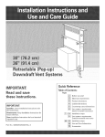
PROPANE
HEATER
●
11/-?h-.a
>
.
F
R
,
/
/’””
-9
I
DUAL
UT
/
L
\
FWPANE
WSE
TO TANK
,
\
c=iacuw
,,
\
.NOTE:
DIJAL
OPT
(*EMICAL
—.
SYSTEM
1
OPTIOM
OWL
\
-.
—-. -
..—. ..—
.—-—.
DUALfiYD6?A
I
““
‘\/
.
PUMP-IN
KIT
SHOWN)
UT
M PRESSUE
WJTION
OUT
#
0RAWM4G NO
CAT COMPONENTS
.———.--=.
CAT
IONAL..
“-
‘-*
~ti ~ - ~o-_{3
1
pu2LLm
HYDRA
Freeze
the heater
guarding
off.
STRETCH
should
FREEZE
GUARD
be performed
PROCEDURE
prior
to shut-down
with
1. Remove clear chemical feed hose from chemical jug and insert
into container of 50,/50 anti-freeze
and water mixture.
2. Run unit, siphoning anti-freeze
1!3 GPH an the flow meter.
mixture
for 10 seconds
at
~. Turn unit off. Disconnect
inc. water supply to machine.
knob on bypass valve to allow air to flow through system.
4. Open
drain
on mix
Loosen
tank.
5. Insert freeze guard hose onto low pressure in quick connect.
Turn on freeze guard pump until only air is entering the mix
tank.
6. Disconnect
freeze
guard
7. Connect the alternate
out quick connect.
Turn
in the mix tank.
hose
from low pressure
in quick
freeze guard hose to the high pressure
on freeze guard pump until air appears
8. Plug in all hoses and tools which will require freeze
to the freeze guard quick connect.
Turn on freeze guard
until water is voided from tools.
9.
Clase
drain
valve
connect.
on mix
tank.
guarding
pump
OPERATION
PRECAUTIONS
MACHINE ADJUSTMENTS:
ALTHOUGH THIS UNIT HAS BEEN FACTORY
ADJUSTED IT MAY REQUIRE ADDITIONAL
ADJUSTMENTS TO ACHIEVE OPTIMUM PERFORMANCE; I.E. ALTITUDE MAY REQUIRE
CARB ADJUSTMENT AND AMBIENT TEMPERATURES MAY REQUIRE HEAT CONTROL ADJUSTMENT.
WHEN REQUIRED, RE-ADJUSTMENT MUST BE ACCOMPLISHED BY AN AUTHORIZED HYDIW-MASTER REPRESENTATIVE OR
WARRANTY MAY BE INVALIDATED.
ENGINE COOLING:
UNITS EMPLOYING AIR COOLED ENGINES
MUST NOT BE INCAPACITATED WITHIN A
VAN WITH DOORS AND WINDOWS CLOSED.
EXCESSIVE TEMPERATURES WITHIN THE
ENGINE WILL RESULT IN PREMATURE
ENGINE FAILURE AND A COMPROMISE OF
APPLICABLE WARRANTY
A. WHEN RUNNING THE AQUA CAT
THE COLD WATER SOURCE MUST
BE CONNECTED TO KEEP ENGINE
PROPERLY COOLED.
LEVEL :
FREEZE PROTECTION:
DURING OPERATION, VAN OR TRAILER MUST
BE PARKED ON LEVEL GROUND NOT TO EXCEED
+ORFAILURE TO INSURE PRO10 DEG..
PER LEVELING MAY PREVENT PROPER INTERNAL
LUBRICATION Ol? ENGINE, VACUUM AND/OR
HIGH PRESSURE PUMP COMPONENTS.
ALL UNITS ARE EQUIPPED WITH FREEZE
PROTECTION DEVICES AND/OR INSTRUCTIONS PROVIDED ON OPERATING LABELS
FOR THE PREVENTION OF FREEZE DAMAGE.
FAILURE TO PERFORM RECOMMENDED STEPS
OR USE SYSTEMS DESIGNED FOR THIS PURPOSE CAN RESULT IN EXPENSIVE COST, DOWN
TIME AND COMPROMISE TO APPLICABLE WARRANTY .
10
ONAN ENGINE
An Onan instruction brochure is included with this manual (see
index) which may assist you in resolving an engine related problem.
PROBLEMS:
ENGINE
ENGINE
ENGINE
ENGINE
ENGINE
LOW
FAILS TO START
RUNS ROUGH
BACKFIRES
FAILS TO ACCELERATE
REDUCES SPEED TO
RPM UNDER LOAD
CAUSE AND/’OR SOLUTION
1. Loss of fuel
2. Blown master
A. Empty gas tank.
B. Plugged fuel line or
filter.
c. Defective fuel pump.
D. Gas line kinked or
crushed.
1
fuse A. Electrical short.
B. Defective fuse.
3. Oil on points
A. Consult with Onan for
possible modification
or replacement of seals
within point box.
B. Drill a 1/8”’ hose
through point box cover
and gasket to alleviate
vacuum.
4. Worn or maladjusted points
A. Remove and replace
points and condenser.
B. Clean and adjust points.
5. Defective
plugs
A. Remove and replace.
B. Clean and regap.
spark
e
6. Defective spark
plug wires
A. Spark plug wires along
with many others may,
at certain points, come
in contact with heated
parts (exhaust manifold)
or abrasive parts
(sharp metal, teflon
hose ). This may be taken
into consideration for
electrical shorts.
B. Remove and replace.
7. Low compression
A.
B.
c.
D.
Defective valve.
Stuck valve.
Worn compression r~ngs.
Defective piston.
a
12
—
ONAN ENGINE CONT.
8. Float switch in
recovery tank
(NOTE: temporary
repair permits
disconnection of
float switch
wire from point
box terminal.
Continued operation with this
condition will
compromise Vat.
Blower) .
A. Switch stuck in
upright position.
B. Defective float
switch.
c. Float switch may b~
obscured with lint
or debris.
9. Engine will not
turn over
A. Dead battery.
B. Loose terminal
connection on
battery or ignition switch.
c. Defective starter.
D. Seized engine or
Blower, pump,recirculating pump,
could cause engine
to not turn over.
use process of elimination to aid in
further diagnosis.
E. Often anodizing will
prevent electrical
system from grounding properly.
10. Defective
uretor
11.
carbA. Clean Carb.
B. Replace Carb.
c. Choke locked in
closed position.
D. Often Carb float
level comes out of
adjustment. This
should be set by
holding carb upside
down and the float
should be at 3/16.
Improperly adjA. Incorrect air mixusted carb (NOTE:
ture ratio adjusta comprehensive
ment.
manual is availB. Incorrect float
able and defines
level adjustment.
necessary adjustments. )
12A
~
~
12. Carbon build-up
in cylinders
(NOTE: carbon
build-up can be
minimized by
using unleaded
reg. gas. Should
carbon removal
be necessary,
reinstall heads
with new gaskets)
A. Carbon build-up
may be excessive
if-carb or valve
are improperly
adjusted, enginee
RPM tOO 10W, -ireproper spark plug
gap.
B. Remove cylinder
heads and eliminate carbon buildup with wire brush.
13. Incorrect
A. Timing may become
offset if point
box is not secure
or if points are
out of adjustment.
B. Refer to Onan Maintenance instructions
for details.
timing
14. Dirty air cleaner
A. If exhaust gaskets
do not seat properly or heat exchanger gasket is bad,
exhaust may heat anti
melt the air cleaner
requiring much clear
up repair.
B. PCV valve may b
cleaned by r~nsi9 g
thoroughly with
solvent.
c. Remove and replace
or clean as required.
15. Clogged
A. Remove and replace.
fuel filter
16. Low oil level or
malfunctioning oil
pump
A. Oil pressure sen–
sors can be installed on the
engines. This will
eliminate many prablems which may occu~
~
VACUUM BLOWER
POSITIVE
DISPLACEMENT
A Blower Instruction brochure is included with this manual (see
index) which may assist you in resolving a blower related problem.
PROBLEMS:
NOISE IN VACUUM
CAUSE AND/OR
BLOWER
1. Loose direct drive
coupler
A. Examine coupler boot
for defects and retighten lock bolts.
(Refer to coupler
drawing) .
B. Replace coupler boot
if it is either torn
or punctured.
2. Worn gears
A. Remove and replace
gears. (NOTE: replacement of gears must be
accomplished by qualified technician) .
B. Timing of vacuum blower
has been changed due to
worn components.
Replacement of components
must be accomplished by
a qualified technician.
\
.
SOLUTION
3. Lack of lubrication
(NOTE: Permanent
damage may have
resulted from lack
of ‘lubrication) .
A. Lubricate as specified
by applicable vacuum
See
blower manual.
index.
4. Worn bearings
A. Remove and replace
bearings as required.
Must be accomplished
by a qualified technician.
5. Debris andior foreign A. Disassemble vacuum
material build-up
blower and remove
(NOTE: A stainless
foreign material.
steel filter is pro(NOTE : Disassembly
vided in vat. inlet
should be accomplish~~d
located in vac tank
by qualified technito protect vacuum
Replacenwi~t
cian only.
blower components) .
of worn parts is recom–
mended if this procedure is necessary. )
6. Loose or missing
mounting bolts
A. Tighten or reinstall
mounting bolts.
13
VACUUM BLOWER
(CONT. )
\
J
PROBLEM:
LOSS OF VACUUM
CAUSE AND/OR SOLUTION:
1. Defective or maladjusted vat. relief
valve
o~
A. Examine, replace if necessarv
—.
and\or ad-ju;t vac relief valve.
2. Collapsed vac hose
between blower and
vac tank
A. Remove and replace hose (NOTE:
a special reinforced hose is
required for replacement. )
3. Clogged stainless
steel filter
A. Remove and clean or replace
S/S filter.
4. Defective
seal
A. Remove and replace vac tank
seal.
vac bank
5. Defective or “open”
vac tank dump valve
A. Close valve
B. Replace valve.
6. Fractured
vac tank
weld on
A. Re-weld
tank.
7. Collapsed
vac hose
or kinked
A. Reshape hose if possible
eliminate kinks.
8. Plugged vac hose
A. Remove obstruction.
9. Restriction in
cleaning tool
A. Remove obstruction.
10.
Worn end plates or
lobes in vac blower
11. Loose doupling system
between engine and
blower
BLOWER
IS SEIZED:
as required
1. Rust
Foreign matter
3. Seized
or replace
and/or
o
A. Replace worn components. (NOTE:
must be accomplished by a
qualified technician.)
A. The set screws may come loose
causing blower to stand still
while engine may be turning
properly. (NOTE: unless the
blower is seized or making
a knocking noise, your vacuum
loss is not caused by a bad
blower. )
A. Spray rust disolving lubricant
onto lobes to emulsify rust and
attempt to rotate vacuum lobes.
A. Disassemble and remove foreign
matter and repair as required.
(NOTE: disassembly must be
accomplished by qualified
technician.
A. If you suspect that your
blower has seized, remove
coupling element then run
engine for a few seconds. Thl&Q
way you wont confuse similar
problems.
i
.
.
!@
H\C,
E@..
i)/C . . . . . .
}
280
43CJ
E!El
ENGINE
DIP STICP
CAR8LJRETOR
CHOKE
i
\
RE
TMENT
w
OIL
FILL
r-’%’”
P
●
w-OIL
GREASE
FITTING
!4
)1I
DRAIN
\
f$i---c!w
liJ--
OIL DR$UN
“m--’”
DUAL/HYDW
CAT WINTENANCE
Eslll’d
I====d
L——J—”
Cat
a
Pump
there
As you remove your discharge manifold,
is a set of 3 check
valves (which usually fall out during dis-assembly) . If the surfaces
of these check valves are dirty, or show signs of chemical build-up,
it is probable that they would remain open causing pressure loss or
pulsation.
Upon inspecting
the valves, make sure that the teflon
buttons in the valve spring retainers are still intact.
Also examine
the discharge manifold.
Look for problems such as cracks, chemical
build-up or warpage due to freezing.
If this discharge manifold is
warped, it will cause the check valves to stick and will result in
loss of pressure.
The Cat pump cups are often the source of pressure loss.
Upon inspection they may appear melted or torn, but often they will look good.
Replace them anyway.
There is no sure method of visually inspecting
the cups.
Hydra-Master
recommends
changing cups whether they look good
or not.
Anytime your pump is being dismantled,
Hydra-Master
recommends replacement of all ‘o’ rings and seals.
This is merely a convenience
to the customer to make sure that the Cat pump is in top operating
condition.
The prrrm-a-lube
seals located within the intake manifold will allow
air to enter the pump if they are worn.
Again, it is difficult to
visually pinpoint a defective prrrm-a-lube
seal.
Replace them all.
e
Within the piston sleeve cylinders there are 6 ‘o’ rings that are about
1/4 the size of a penny.
If these ‘o’ rings are bad, water will be
pumped back into the oil.
If this has occured the oil will raise
in level and will appear milky.
If you are unable to repair seals
right away, change oil frequently.
Repair the pump as soon as possible
so as to not damage bearing or connecting
rods.
Repairing of Cat pumps is not a difficult task, however,
assembling make sure you have the proper parts required.
1 63 1 -
before
dis-
short (or hot) cup kit
piston sleeve ‘o’ rings
Prrrm-a-lube
seals
bottle Cat oil
Read instructions
thoroughly,
supplied in the Cat pump manual, prior
to disassembly
and follow directions
as stated.
Oil all seals thoroughly
prior to installation.
(Remember, a newly scarred seal is no better
than the one you just took out.)
liIG1~PRESSURE
PUMP
A pump instruction
brochure
is included with
index~ which may assist you Ln resolving a pump
PRCIELEMS :
LOSS
OF PRESSURE
CAUSE
AND/OR
this manual’.
(See
related problem.
SOLUTION:
1
Clogged filter screen
in garden hose quick
connect coupler.
A. Remove and clean
or replace filter.
2
Low water
source
at
A. Determine
rate of
flow and select an
alternate
source of
supply if water
pressure
is inadequate.
3. Defective
or blocked
check valves in high
pressure pump cylinder
head
cylinder
A. Disassemble
head and replace or
clean applicable
check valve.
4. Delaminated,
kinked or
clogged hose between
the mix tank and the
high pressure pump
A. Remove and replace
defective
hose.
a
pressure
5. Defective
relief valve or debris
in pressure relief
valve
A. Disassemble
and clean
pressure
relief valve
as illustrated
in
drawing.
pressure
or
B. Replace defective
worn out bypass cup.
c. Replace
or worn
6. Defective
piston cups
bypass
valve.
A. Remove and replace
piston cups as defined by pump manual.
7. Obstructions
in internal hoses which feed
water to the pump
A. Remove obstruction or replace
affected hose.
8. Pump and/or
water
A. Repair and/or
replace item
causing leak.
(NOTE: Worn sea?.:within the pump
will cause leak-ing while cleaning tool is notin use but will
suck air as clc.J::-ing tool is tur:ed on thus resc,;t,
ing in a pressure
loss. )
9.
hoses
leak
Defective
clutch
(NOTE : If electric
clutch fails to
engage, power cannot
be transferred
to
high pressure pump.)
a
10. Loose drive belt
for high pressure.
pump
A. Examine electrical wiring and
switch to ensur:
power is suppli:d
to clutch.
B. Examine low water
level float sensor
at the bottom of
mix tank for
possible restriction.
c. Remove and repl?cc
electric clutch
A. Readjust belt a
required or replace if defective.
14A
I
I
1. Damaged
seal
LOSS OF/OR ERRATIC
CHEMICAL
FLOW
piston
rod
1. Clogged chemical
tank filter
A. Rebuild piston rod
assy. and replace
applicable
*Q* ring.
a
and seals. (NOTE: Failure to comply may compromise the high pressJure pump and cause its
total destruction.)
A. Clean or replace chemical tank filter.
2.
Defective
control
valve on chemical
flow meter
A. Remove and replace
valve assembly.
3.
Cracked or split
chemical feed hose
A. Remove
hose.
4. Cracked chemical
flow meter
and
replace
A. Remove and replace
flow meter.
5.
Air leak or water
leak from chemical flow meter
to mix tank.
A. Inspect hose and
fittings for possible
fracture.
(NQTE: Even
the most minute fracture may cause seve
variance
in chemical *
flow readings).
6.
Clogged or defective metering
valve in the mix
tank
A. Inspect
and
repair.
I
14E
a
DIRECT
VIBRATION
:
MISALIGNMENT
DRIVE
COUPLER
Tighten bolts and allen screws.
(Also allen screws that secure
pulley to shafts of electric
motor and blower) .
:
Due to loose bolts on electric
motor or blower mounts.
OVER-FILLING
PROPANE
TANK (NOTE: Propane
heater is designed
to operate on vapor
propane only - NOT
LIQUID PROPANE.
Over-filling
propane
tanks forces liquid
propane into the heater causing an overrich condition which
creates carbon or soot
build-up within the
. heater core.
Restrictions due to this problem compromise
the heating ability of the heater and render an unsafe
condition.
Over-filling
the propane tank can be
prevented
if filling
procedure
is stopped
when white vapor is first
emitted from the propane
tank.
Only authorized
and
trained personnel
should
fill propane tanks.)
RESTRICTION
OF AIR FLOW
AT BASE OF HEATER.
A. Remove any article such
as chemical containers,
hose, boxes, etc. , within
18 inches of base of heat(NOTE: This situaer.
tion also creates an
over rich condition which
results in carbon buildup as described above.
Carbon removal is accomplished in the same
manner. )
,.
I
15A
LOSS OF TEMPERATURE
DUE
TO COLD WEATHER
(NOTE:
Climactic
changes alter
the output capability
Example:
of the heater.
The propane heater is
designed to elevate the
temperature
of a given
amount of water in a
given period of time.
Water emitted from a
faucet ar 50 deg. on a
warm day may increase
in temperature
as much
as 20 deg. before entering the heater thus
resulting
in a 20 deg.
boost in temperature
once
heated.
An additional
benefit is experienced
since warm air is also
drawn into the heater
and provides an additional
boost in temperature.
Conversely,
winter time
operation
alters the performance of the heater
capability
since water
leaving a faucet at 50 deg.
may lose 10 - 13 deg. in
temperature
before entering
Likewise, the air
the heater.
drawn into the heater is also
colder, thus reducing the
This
overall performance.
condition
is natural and
cannot safely be altered by
It may
any mechanical
means.
therefore be assumed that
efficiency
levels will vary
in relationship
to the climate.
15B
I
~. WORN OUT SPRAY JET
(NOTE: Cleaning tools
designed to spray a
constant flow of 1+
GPM will average 1
gallon of flow per
minute on actual working situations since
flow is not continuous.
An average flow of 1
GPM results in 6000
gallons of flow for
every 100 hours of unit
Spray tips
operation.
are capable of consistent
flow rates for approximately 20,000 gallons.
They should be replaced,
therefore, approximately
every 350 hours.
Worn
spray jets allow a greater
average rate of flow thus
reducing desired temperature levels.)
A. Remove and replace
spray jet.
a
10. REDUCTION OF FLOW due to
increased length of solution hose. (NOTE: For
every 50 feet of hose,
beyond 200 feet in total
length, a measurable
loss
of flow is experienced.
This condition is a result
of the increased friction
experienced
by the water
as it passes through the
As has been indihose.
cated above, reduction in
flow automatically
reduces
propane metering thereby
The
reducing temperature.
proper balance of flow can
be reinstated by simply
changing the cleaning tool
spray jet to the next larger
Example: if your
size.
cleaning tool contains an
8006E spray jet, you would
change it to an 8008E to
compensate
for any losses
in flow due to the addition
of solution hoses.
1Kr
m
‘a
a
11. FOREIGN MATERIAL IN
HIGH PRESSURE BYPASS
VALVE . (NOTE: The high
pressure bypass valve
is designed to fully
close when the cleaning
tool is turned on.
-y
foreign matter collecting
on the piston will prevent
full closure of the valve
and allow a portion of the
water to continue to circulate instead of being
routed to the cleaning tool.
To correct this situation,
the bypass valve must be
disassembled
and cleaned
(refer to drawing provided
in this manual for bypass
disassembly) .
12. FROZEN OR DAMAGED QUICK
CONNECT FITTINGS.
(NOTE:
Couplers which have been
frozen often impede the
flow of cleaning solutions
and adversely affect the
heater as defined by previous
comments pertaining
to the
reduction of propane metering
to the heater.)
A. Remove and replace
damaged fittings.
#18 Yellow
Flame
A. Liquid propane entering into system due to (1) over-filled
propane tank, (2) truck driven with propane tank valve
opened,
(3) truck parked on an incline.
Hoses with liquid
propane can be flushed with alcohol.
due to (1) liquid propane
H. Propane regulator malfunction
obstructing
vapor flow, (2) dirt or dust entering through
vent port on the propane regulator
(this may be remedied
by using Tupperware
cover supplied by Hydra-Master
for
propane regulator),
(3) over pressurization
of propane
regulator,
caused from filling propane tank with valve
opened, will cause warpage of the regulator.
Replace
immediately.
c. Dirty heater core will prevent flame from being vented.
A blue flame is required to achieve maximum heat.
Oxygen
must be vented with the propane to achieve maximum heat.
D. Dirty
cient
or malfunctioning
burner assembly
propane and oxygen mixture.
will
cause
a<
insuffi-
,
I
1
—.-....——
..—-———
-— ———
16.
CLOGGED FILTER SCREEN IN
A. Clean screen
GARDEN HOSE QUICK CONNECT
replace.
FITTING.
(NOTE: Refer to
step #14).
IMPORTANT: Permanent removal
of the filter screen may compromise the total integrity
of water flow throughout
the
unit.
The incoming regulator,
heater water flow valve, high
pressure pump and high pressure bypass valve may be adversely affected if foreign
material is permitted to pass
through them.
Alterations
of
this type void Hydra-Master’s
warranty on all water related
components.
17. FLAMES
HEATER
PROTRUDING
COVER.
OUTSIDE
or
OF
A. Overfilled
propan{.
tank causing
liquid instead of
vapor to enter
heater.
B. Heater core clogged
with carbon or soot
and requiring
cleaning.
c. Incorrect adjustment propane reg1’
ulator.
D. Defective or malfunctioning
burner
valve assembly.
EXCESSIVE
PILOT
HEAT
LIGHT
1. Maladjustment
of propane
(NOTE: propane
regulator.
regulators
are factory preset and may be readjusted
by authorized
Hydra-Master
personnel. )
A. Contact Hydra-Master
Corp. to determine
correct procedure.
a
2.
Overfilled
propane tank
(NOTE: Hydra-Master’s
propane heater is designed
to operate on vapor propane
only . Over-filling
a propane
tank allows liquid propane
to enter all heater related
components
and permits an
over-rich burning condition
to oc~ur. This condition
usually requires the heater
core to be cleaned of soot and
carbon deposits. Cleaning may
be accomplished
by removal of
heater core and application
of
a household
oven cleaner.
Following
application
of oven
cleaner, rinse residue with
clean water.)
4.
Propane resi.due/deposi.ts
collecting
in burner assembly.
(NOTE: Burner assemblies
are
factory sealed and must be
cleaned by trained technicians
only. Failure to comply may
compromise
operator and
equipment
safety.)
A. Remove
burner
5.
Flame remains
complete when
spraying.
A. Debris in heater water
regulator.
B. Heater water regulator
has frozen.
c. Replace poppit valve.
D. Check pump protection
system for leakage.
partial or
wand is not
1. Pilot light will not ignite.
(NOTE: do not use a needle
or pin to clean pilot orifice
- use compressed
air or solvent
only.)
See IMPORTANT
Note,
Next
Page.
and replace
assembly.
A. Verify propane reaching i~ni.tor. (NOTE: a
kinked or
crushed ho~may impede propane ~
)
B. Remove and clean ori* cc
C. Verify igniter spark is
operating
correctly.
IMPORTANT:
MAIN
BURNER
If a new propane tank has been
installed or hoses have been
disconnected,air
may enter propane hoses and must be purged
prior to attempting to light
Should this
the pilot burner.
condition exist, operator mu”st
depress the pilot button for
3-5 minutes and attempt to ignite
the pilot light at 30 second iriA very slight hissinu
tervals.
noise should be evident while
performing
this operation.
INOPERATIVE
IMPORTANT: Hydra-Master’s
propane heater
will only ignite under normal conditions
with the ckeanffig tool turned
Any partial or full
on.
burn condition without
cleaning tool turned on is
abnormal and must be corrected
immediately
to prevent personal injury or equipment
damage.
1. Clogged spray jet
(NOTE: any reduction
in solution flow
automatically
limits
the amount of propane
metered to the burner
Full or
assembly.
partial blockage will
render the heater inoperative. )
A. Remove jet and
clean as requirec
2. Kinked
A. Unkink
hose.
hose
or repla ~~
3.
Damaged water flow
valve at base of
heater.
(NOTE: refer
to preceding
instructions. )
A. Remove and repa~”
or replace water
valve.
4.
Water valve diaphragm
ruptured or distorted
through normal use.
A. Remove and r“.place water ‘~alv
diaphragm.
See IMPORTANT
Note,
Next
page
15E
IMPORTANT: The function of the
incoming water regulator is to
balance the demand for water to
a position whereas chemical will
be siphoned from the chemical tank.
Rotating the regulator counterclockwise too far results in loss
of pressure, loss of temperature
and total loss of chemical flow
and compromises
internal components
of the high pressure pump.
6.
Clogged garden
strainer
hose
7. Low water pressure
from source
8.
Kinked garden hose
or water supply hose
9. Defective
regulator
propane
a
A. Remove and clean or
replace strainer.
A. Locate
alternate
source.
A. Remove kinks and verify
flow has been re-established.
A. Remove and replace
regulator.
10. Loss or reduction of
A. Determine cause of
high pressure
pressure loss and
(NOTE: Any reduction or
repair as required.
loss of high pressure
adversely affects flow
rates and may cause heater to shut down automatically. )
11. Foreign material in
high pressure bypass
valve (NOTE: Excessive
amounts of foreign material may alter flow
causing automatic shutdown of the burner
assembly.)
a
A. Disassemble
and clean
bypass valve as required.
(See drawing).
ELECTRICAL
e
SYSTEM
The entire electrical
system operates on 12 volts DC which is
provided by a battery located at the rear of the vacuum holding tank.
Battery levels are sustained by a 15 amp alternator designed within
the engine.
A comprehensive
schematic is ~rovided
which details the
.
entire electrical
system and it’s components.
PROBLEM
LOW BATTERY
CAUSE
VOLTAGE
AND/OR
1. Defective
SOLUTION
battery
A. Remove
2. Corroded battery
terminals
3.
Low battery
4. Defective
regulator
5.
e
A. Clean terminals
battery posts.
fluid
voltage
charging
and
A. Add water to appropriate level.
A. Remove and replace
voltage regulator.
Loose wiring within
electrical
system
6. Blown
and replace
fuse
A. Examine all terminal connections
and verify that they
are secure. (NOTE:
give special attention to ignition
switch terminals
and voltage regulator terminals.
A. Remove
fuse.
B. Check
and replace
battery
charge
c. Check battery cells
with hydrometer.
7.
Electrical
short
wiring system
8.
Poor ground
tion
in
connec-
A. Examine
systems
wires.
electrical
for bare
A. Examine terminal
remove corrosion
necessary.
and
if
B. Follow ground wire
from (-) of battery
to where it grounds
at the frame. If it
is grounded to anodized aluminum then
scratch some of the
anodizing off to
allow for circuit to
be completed through
the aluminum.
9.
INCIPERATIVE TEMPERATURE
GAUGE
INCIPERATIVE
HOUR METER
Defective
alternator
A. Remove fly wheel
housing and fly
wheel to expose alternator and remove
and replace alt
nator. (NOTE: a *
1
ified technician may
be necessary to perform this function.
1. Temperature
doesn’t
register or gives
a false reading.
(NOTE: the integrity
of the temperature
gauge can be determined by simply
turning on the ignition switch and
shorting the temperature sending
unit wire to ground.
If the needle on the
temperature
gauge
deflects to maximum
temperature,
it may
be assumed that the
temperature
gauge
is good. It would
then be necessary
to replace the sending unit only.)
A. Examine all wires
leading to and from
the gauge including
the temperature
send
ing unit wire.
2. Temperature
gauge
reads maximum upon
turning key to ignition/
A. Ba_&tery terminals
may be interchanged.
1. Time is not advancing correctly
A. Verify 12 volts
is available at
hour meter with
ignition switch
turned on. This
be accomplished
a volt meter or
test lamp.
B. Remove and replace
sending unit.
C. Remove and replace
temperature
gauge.
DC
the
the
can
with
a
B. Remove and replace
hour meter if 12
volts is available.
C. A nylon gear within
the clock may have
been jammed due +
e
a sudden jolt o
e
machine ot truck.
You may try simply
tapping on the met{’r
to try to free the
nylon gear.
b
x(’
x
-1
0
..
U-.
Q
c%)
“
-----
U
●
b
-a
1
I
i
./
1
--
u
R’
●
u------
9“
-.-*
INOPERATIVE
a
o
ELECTRIC
HIGH PRESSURE
CLUTCH
-
PUMP
The High Pressure Pump clutch is designed to operate
when
pressurized
water is connected to the units incoming water fitting.
A pressure switch has been incorporated
to protect the clutch from
accidental
activation.
It
will also disengage the electric clutch
if water pressure drops below 5 PSI.
1. Clutch
engage
,.
will
not
A. With the use of a
jumper wire, bridge
pressure switch terminals to determine
integrity of pressure
switch and clutch.
If
clutch engages with
pressure switch shunte ,
replace pressure switc
If clutch does not engage, verify 12 volts ..:
is available at the
electric clutch.
(NOTE :
Verification
can be accomplished by using a
volt meter or test lamp. ~
B. Verify battery is fully
charged and capable of
supplying necessary voltage and current to engage electric clutch.
(NOTE: The integrity o:
the battery and chargi],,,
systems must be determined by a qualified
technician with proper
test equipment.)
c. Remove and replace clu~.ch
if A and B reflected
above indicate sufficient
voltage and power is
available.
Ihl+
11-M
1-79
IjoB cA’r - liYDRA CAT - DUAL CAT
MARE
IV
-
MARK
V
TROUBLESIIOOTING
M~ny of the malfunctions
which can occur ~re minor ir~ nature
and can be rectified with minimal effort.
Unfortunately,
we fre~~uenkly have a tende[]cy to ex~mine the unit as a whole and not
direct our
attentioIl
to the actual problem, which is a system
within the entire unit.
Re~lizing that downtime is our worst
enemy, and that troubleshooting
a problem can be extremely easy
if we understand the functional systems, components,
and the
method with which they interplay with one another, we must determine to become involved.
Example: Do not address a chemical feed
problem with the electrical
system.
In the following pages we shall endeavor to identify both a
problem and its probable cause and solution.
Only those problems
which are determined
co have a more frequent cyclic occurance
will be reflected within this section of the manual.
Isolated
situations
will
rrot
be
included.
After exhausting the possibilities
contained herein, you are encouraged to contact either an authorized Hydra-Master
Service Center or Hydra-Master’s
Service Department for additional solutions.
A minimum of information
is recommended prior to contacting either of the above.
A list is provided for your needs.
1. Engine
R.P.M.
without
vacuum
2. Pressure - high pressure
turned off and turned
(NOTE: Any pulsations
or solution
hoses
attached.
~eadings with both cleaning
on.
should be indicated).
3. Vacuum levels with intake port on vacuum recovery
completely blocked.
(NOTE: With the use of a tachometer, determine
R.P.M. under a maximum load condition).
tool
tank
engine
4. Rate of flow emitted from cleaning tool for a 60 second
period.
1$ gallons per minute is desired
(NOTE : Approximately
with 100’ solution hose attached to the cleaning tool) .
5. Maximum temperature as reflected by the temperature gauge.
This reading should be taken with 100’ of solution hose
The thermostat
dial for
attached
to the cleaning tool.
this reading should be on Very Hot with the tool spraying
for 3 minutes constantly.
CHEMICAL
No or Low Chemical
Flow
TANK
TROUBLESHOOTING
- 1. Check that hoses in the tank are
secured. Check that the hose from
the top of the flow meter to the
side of the mix tank is secured
with no kinks. Check the hose from
the bottom of the flow meter to the
them. jug for kinks or cracks.
2. Check the anti-siphon
screen on the
end of the hose which goes into the
mix tank. To check this screen for
proper function, remove it from the
plastic hose. You should be able to
suck through the hose barb end, but
you should not be able to blow through
the hose barb end. (If you can not
suck through it then rinse it out with
vinegar.
...
m
NOTE : If you are in a low water pressure
area and find that the volume of
water entering the mix tank is not
enough to allow your venturi to
siphon chemical, unscrew the spring
from the anti-siphon
screen and cut
off 2 coils. Screw the spring back
into position.
Inability to adjust
chemical with the flow
meter
Solution reversing from
mix tank to chemical jug
a
Mix Tank
overflows
3.
Check
4.
Turn
wise
1.
Debris lodged behind
flow meter knob.
2.
Teflon seat dismounting
meter knob.
1.
Anti-siphon
screen
ical jug hose.
2.
Debris
1.
Float ball in mix tank
(not moving freely).
2.
Extension bracket pinchinq the float
lever, restricting- full a;tion of the
lever.
flow meter
for float
obstruction.
incoming water regulator clockto increase water flow volume.
teflon
from
removed
in anti-siphon
seat
in
flow
from chem-
screen.
hanging
up
m.x Tank overflows
(cant. )
Mix Tank doesn’t keep
up with water output
Pump pulsates when the
tank is in a fill mode
3.
Plunger nor seating properly on the
valv@. (Remove the 2 screws which
hold the extension assembly to the
valve. Do not lose or drop the screws.
Remove the extension assembly. Turn
it upside down. Inspect the plunge~
for proper seating. If there is no
debris obstructing
the valve or
plunger, the plunger may be out of
adjustment.
To adjust, loosen the
set screw on the retainer ball and
move the ball toward the end of the
rod 1/16”. Retighten set screw. Place
extension assembly back into position.
Tighten the two screws.
1.
Check garden
bly screen.
2.
Check garden hose and/or feed hose to
the mix tank for clog’, kinks or blockage.
3.
Turn incoming water regulator handle
clockwise to increase water inlet flow.
4.
Float ball in mix
moving freely).
5.
Extension bracket pinching float lever,
restricting
full action of the lever.
6.
Valve plunger not opening fully. To
adjust, remove the 2 screws which hold
the extension assembly to the valve.
(Do not lose or drop the screws).
Remove the extension assembly, turn
it upside down. To adjust, loosen the
set screw on the retainer ball. Place
your thumb on the plunger and press
it in 1/16” and slide the set screw
retainer ball toward the plunger end
1/16” . Tighten the set screw. Place
the extension assembly back into position. If the tank starts to overfill,
the retainer ball is too close to the
plunger.
1.
Check that the hose which goes from
the gray plastic venturi to the bottom
of the tank is not directed toward
the Cat pump pick up port. If it is,
aim it in another direction.
hose quick
connect
tank hanging
@
assem-
up.
(Not
a
a
I
‘t
e
.
1*
---
‘, ----
\
1
t-).-Y
z
1
I
‘$&
E,
$
HYDRA
STRETCH
PLUMBING
Your Hydra Stretch plumbing system is unique to all other
Hydra-Master
plumbing systems and is incomparable
throughout
This system has been designed
the carpet cleaning industry.
to be the most simple and trouble-free
ever.
The incoming water flows through the incoming water regulator which should be set at about 20 PSI at the mix tank.
Water will now flow through a proportioning
valve which will
simultaneously
mix the chemical to achieve your desired soluThe mix tank is equipped with 2 different
float valves,
tion.
one of which responds to the water level of the tank and will
maintain the proper volume of solution to be reserved for the
Cat pump.
The secondary float valve is a safety valve that is
designed to protect your system from sudden or unexpected
loss
of water supply.
If, for example, the water source at the house
was
turned ‘of+’ , the water le;el of the mix tank would drop
disengages
activating
the secondary valve which automatically
the electric clutch on the Cat pump.
a
In conjunction
with the incoming water flow, the chemical
ratio may be obtained by an adjustment
of the chemical flow
The chemical will
meter during the fill cycle of the mix tank.
flow from the chemical jug to the chemical flow meter, then to
the proportioner
where it is distributed
into the mix tank at
your desired proportion.
This line should be flushed with
This may
vinegar weekly to prevent abnormal chemical build-up.
be done by removing the clear plastic hose from the chemical
jug and inserting
it into a one quart container of vinegar.
This should be done with the chemical flow meter setting on 10
GPH with both heaters off.
Simply spray the wand for the duration of the vinegar in the one quart container,
then repeat the
process with one quart of clear water to void all lines of
vinegar.
NOTE: With this unique chemical system, your chemical flow
is proportioned
to the filling cycles of the mix tank, not the
direct spraying of the wand.
Therefore,
it is possible that as
Also the
your wand is spraying, you may have no chemical flow.
converse is true in that you may not be spraying your wand but,
if the mix tank is in a filling cycle, your chemical flow meter
may read your desired flow.
Hydra
Stretch
Plumbing
- page
2
The water will now be siphoned from the bottom of the mix
If neither of the wands are spraying,
tianlcto the Cat pump.
the water will bypass from the bottom of the brass pressure
relief valve to the mix tank.
If the wand ar wands are spraying, the water will then flow
ho the desired heater.
This heater has a capacity of up to 5
gallons, therefoxe,
it is extremely
important that all air is
bled
out
of the heater prior to initial start-up.
This may be
achieved by running the system, without the heater on, for
approximately
60 seconds.
This heater is thermostatically
controlled,
therefore,
upon initial ignition of the heater, the burner will fire for
about 1 minute.
Once desired temperature
is achieved, the
With
thermostat
within the heater will turn off the burner.
the design of this heater it is possible that the flame may
be on when the wand is off.
Likewise,
it is possible that the
flame may be off when the wand is on.
The thermostat
dial on this heater should be set so that
once the heater has achieved a temperature
of 170-190 then spray
the wand for a constant 60 seconds, then turn the wand off.
Now
the burner on the heater should remain on for 30-40 seconds.
If
the flame goes out prior to 30 seconds, turn the thermostat dial
to a higher setting.
If the flame on the burner continues to
burn after 40 seconds, turn the thermostat dial to a lower
setting.
This Hydra Stretch water flow technique is designed for
simplicity
in your achievement
of proper PSI, heat and chemical
mixture.
.“
THIS BULLETIN IS INTENDED AS A GUIDE TO QUALlFIEf) FIELD SERVICEMEN INSTALLING
OR REPAIR.
ING ROB ERTSHAW-GRAYSON
THERMOSTATIC
CONTROLS. AS THE MANUFACTURER
OF THE CONTROL,
WE RECOMMEND THAT REPAIR AND ADJUSTMENTS
BE LIMITED
TO THE OPERATIONS
LISTEO BELOW,
WHICH OUR EXPERIENCE
SHOWS ARE PRACTICAL
FIELD SERVICE OPERATIONS.
)
,d”:’+*- ~k;
k
built
to the pIevIous
water iemptxaluie
assembfy shuts
The
additional
In the healer,
function;
a swllch
3.
L
the IIPW Umhr Jl wllh
m case of ex-
inside
prowdes
a completely
self
confawcd
~-’
--
stl
BUITON
———tiA9it
-.
{“b
REIAINtR
N
co,,
(,.s
AS5EMNV
WRING
‘“---GAS COCK
PLUG
gas
shut off system.
V,4LVt
~
:--jr
------
the shank
dutomallc
,,,
-’r’-.
‘:;“’=.;:,,’”:““’t
off the automal!c pIlol valve and alf g,]s to Ihc fleater.
lIOT
Unlhol
01 the Umhol,
the followlng
in ECO provides
cessive
featules
-
[RtDl
GA$ LOCH DIAL
W’-,,’k,w
<
HERE’S HOW IT WORKS
In adchtlon
------2!410
f
AMY
SHANK
ASSEMBLY
\
PILOT
FILIER
- \
\
‘0”’
‘A5Kf’1
\
\
LiCO
I
‘~f<~
\
~1
SWITCli IERMINAL
LCVkR
\
.4---~
l?
\
~\pRtss,,R,
>----=.p
51OP AOJU$lMtNl
‘29]20
DIAL
SCR!W yy14
ADJ C,4P
lCMP
PILOT
A(IJ
SCREW
.KW1
,..
NuT
ySIQP
(IWO I
,--
p::’
MAGNET
HOUSING
‘50455 rERMINA1
ASSEMBLY
RtTAINFR
2/
SCRfW
fxlmsto
(.OVkR
&
1]
PILO1
AOJ
KEY
NOTES:
To [emove GAS COCK and TEklPERATuRE DIAL, pull off (friction fit).
*These Itemsavailable for Ftefd ServiceReplacement.Older by part numbershown above.
GENERAL
DESCRIPTION
The Unlhols 1IOT and 1IOHCT are
stats
with
automallc
CUT-OFF”
device,
adluslable
gas cock,
The Umlrols
and 11OHCT
llOT
by th~ die cast
bt?rs on the smooth
NOTE:
1.
ORDERING
MOD EL(SEE
2.
SMOOTH
1/2
3. SHANK
4.
5.
UN ITROL
OUTLET
of?
CONTROL
TUBE
SIDE
SIZE
PIPE
GTH
HOT
180”(
—
---G
I
contlol
Water
01 mam
all In one compact
and pilot
unit.
can be easily
covers
(fronl
Heater
over temperature
thermo.
“ENERGY
gas, pilot
identified
Iilter
one from the
page) and by the model
num.
side of the body.
These
conhols
covers
bearing
!60”(!IoTI
NoT
INTERCHANGE
“rhe
Unlhol
designed
may be found
the names,
with
decorative
“UNITROL”
plastic
sl[p-on
or “UNITROL
400.”
11OHCT
Ioi
is a high
application
capacity
on appliances
version
of the Unitrol
having
higher
than
11OT
average
—
Btu Input.
I).
-HOT
I loTs)
( ~’,,t~
ST AMP.
1).
FiG.
rum
LIIN6 h
l!!
—
FOR
PIPE
NLY}.
OIAL
-
3/8
FIG.
LENGTti-(sEE
ABLE
F(,,(,N*
TO
front
combination
automatic
11 OI+CT
CASTING
I. F.,
-(SEE
TEMPERATuRE
VERY
OR
OF
1/2
(lloHc
LEN
SPECIFY:
lIOT
bcrllt.m
wllh matn and pilot
other
WEEEN
pilot,
OR
-
The internal
porting
This
m the outlet
resulls
of the 1IOHCT
tapping
IS larger
being
ii16°
than on the standard
closer
11OT.
to the rear of the
body Lmlmg and [he shank protruding 3/16” further behind the body.
The net diflcvence then IS 1/8”.
.;
M4*N*
UNtil”
14B
.
f“--
If ccrntro!wplacernenl IS necessaiy, a ltnilrol 110HCTcan be substituthowever, the Unlliol
llOtf CT must be replaced
ed for a standard lIOT;
anothm
wIltI
A
unlt~o}
Unitml
Unitral
$ervtce
1101-fCT
l10T8
l}OT
(lt30°)
(160°)
f.rlocedures
because
if
and
of gas capacity
must
Ilghlmg
be
not
cmtml
svbstiwted
mplocement
Instlrrc!{ons
is
are
PROCEDURE
FOR LIGHTING
OR RELIGHTING
reqrrlremenls.
for
a
necessary.
IdenlIcJl
for
troth
conhols.
I1OT and 110HCTprov~de:
The Undrols
1.Accurate and
2.
3.
Conven!enf
“Energy
[pilot
depcmtable
built-{fl
water temperature
m31n gas
plessure
Cut-OIf”
Device
and main bu[nwI.
control.
lap.
Complete
high
lImIl
shutoff
of all gds
shut-oli of all gas (pilot aod rnamburnet) In the event of
pIlol oulage.
5. High capacity piiol gds filter ahead01piiot adpMment.
& Easy accesslblhty of dll adjustments.
7. Robeilshaw.Grayson“yoke’’conshucllon which permanentlydlvoices
the watei from the gas passages.
4.
Complete
1.Turn
INSTALLATION
PIPING
hfakesure thal
a small
(’-
the plplrrg IS clean
INSTRUCTIONS
pipe thread compound
amount of gocd qualiy
Th~ead
sparingly
Ieavmg
and on male threads
Pipe dope of thread
only,
compound
as It may be pushed
Iated
and Iree from scale and bulls.
able for the type gas being used.
should
Into the valve
never
compound
the fllst
which
two threads
Depress
Allow
clean.
Ihieads
body.
The
thermocouple
An addlhocral
sufflclenl
pilot
BUTTON.
longer
II necessary,
nut should
quarter
be statted
and turned
turn with a small
10 seat the lock washer.
Coution:
(4”)
all
the way In by
wrench
WIII then be
BURNER
PILOT
MAGNET
AND VALVE
ASSEMBLY
1. Shut off gas at line vdlve or meter.
2. Remove Thprrnocouple.
Iemove red plastlc TERMINAL
RETAINER
3. Wtth small screwdriver,
4. With narlow blade s~rewdrlver,
pry blue SWITCH TERMINAL
{roil]
magnet b~se slot, wr-r[klng from both sides to avoid damage.
by unscrewing
3, 4“ hexagon magnet
5. Remove MAGNET ASSEMBLY
assembly.
MAGNET ASSEMBLY,
apply thread lube sparingly
6. When [eplaclng
and Ilghten suflicit!ntly
to prevent gos leakage.
10
position.
(2) while
one-half
under
=
.~
.( Ion
BLf
Burner
position
!eh
rep~a’
RESET
“Pilot
(1) to “ON”
posltlon.
PIIUI bb-r
before
Itghted,
releasing
as noted
hghtmg
minute
does not remam
before
,adjust
e
Adjustment.”)
and turn TEMPERA-
ADJLfSTMENT
Input):
1. To adjust main burner flame,
‘(C” valve plate (6) clockwlse
Overt lghtenmg may cause
REPLACEMENT
e;
may have accumu.
(Gos
main bu[ner,
In magnet
base slot (It may be nect:ss~ry
10
Rclnslail
TERMINAL
Ieposltlofl
TERMINAL
wires. I
RcInstall
TERMINA[.
RETAINER
(snaps on).
hlslluctions”
for prcrpcr
Rellistall
lhermuctwplc
(see “lnslallal{on
IIwiln,lt IIIIple lnsl.]ll(lllunl.
}{e est~bltsh
gas SIIPIIIY ,Irld lv~h [[”J w!(h WMI) soll]tlm.
or counter-c
loosen
‘(C”
valve
10 decrease
lockwlse
to urc[ease.
(5) turn
screw,
the flow
Tighten
of gas to the
“C”
valve
screw.
PILOT
).
gas which
“PILOT”
BUTTON
If pilot
pellod
5. Turn GAS COCK DIAL
TuRE DIAL (3)todeslred
damage 10 ttre thermocouple or magnet and IS unnecessary.
AUTOMATIC
pOSlllOn.
to burn approximately
RESET
pIlol,
(l)to
dild hold RESET
allowlng
MAIN
“OFF”
In burner compaltmenl to escape. (At least 5 minutes. )
Tu(n GAS COCK DIAL
IS suit-
(l)tu
of time to allow
4.
shou Id be used
be used on female
DIAL
length
3.
Apply
THERMOCOUPLE
hand.
GAS COCK
2. Walt sutllclent
BURNER
1. Remove
2.
AdJust
3.
Replace
PIIo(
ADJUSTMENT
Adjustment
Cap (4).
PIIOI key to provide
Pilot
TO CLEAN
properly
Adjustment
sized
flame.
Cap (4).
THERMOSTAT
VALVE
------COCK UIAL to “Ut 1-”’ posllion.
1.- Turn GAS‘“--’-’”’
2.
Remove
3.
Turn temperature
TEMPERATURE
DIAL
stop to match
and PILOT
opening
4.
Remove toul sclews
5.
Remove
6.
Clean
VALVE
and SEAT
w{th
place
SPRING
and VALVE
ASSEMBLY.
SPRING
1. Reolace
COVER
TiKhlen
screws.
NOTE:
Place
to remove
and VALVE
GASKET.
COVER
AO.IUSTMENT
CAP.
In cover.
and COVER
GASKET.
ASSEMBLY.
Iln[-free
COVER
cloth
and PILOT
w chamois
and re.
ADJUSTMENT
CAP.
‘
gasket
on cove~ and slip
screws
8.
Rel{gl,!
9.
tkpiw
cover on body.
~ ‘ CT ~,tp !’:~; +IJ~: >rour~d gdsket wilh
into cover
belore
placlng
I. TEMPERATURE
main burner
DIAI
14C
“ON”.
le- a
.-
3
TEs.
T NIT
Vll
(M IL LIVOL.
METER)
1{
LI),. < k M~glw+[
T
AJ W,ltl
SIniIll
IL+ I With
Ind{JIII.1
mlna}
SWITCH
TEIIMINAL
SC IewIlr
(I, i!rczw
base
,jilrn
Ivcr
blaclc
remove
E C 0
x!ewdrwer
slol,
pry
worklnq
ftom
terminal
E C O
both
relalner
rermmal
sides
to
from
avo!d
Ihermucw!iik
msldlalmn
Instructions
>wlt Cll tetmlnal OUI Of (Tlagflel
bdSe
staridard
L@htmg
Procedure
I [)1 F olli)w
TE14MINAL
RETAINER
(c:
f’(~ll~~w
(t
Aflel
m
[t~ulmocouple
IrIy
temperature
2 mtnutesl
<II IeJst
II sfluutd
1
ler.
age
remain
out
Ioch(?(l-up
stabilized,
I>
M(IW
for
at
(Pilot
If magnet
pIlol.
least
burn-
IS good
seconds
30
-\
Ieavmg
after
I>!lc)t IS exlmgulshcd
IF J If
IT II ERMOCOUPLE
SE TTINGI
{
FIG
.l
A)
Follow
sliin(],
i((]
closed
blow
Out
IC’, A good
lyntmg
I
~lrcu!t
(Ir
magnel
Check
ECO
(A)
sure
Be
sufe
(n
[AI
I
(61
Elt.
mote
waler
from
locked
original
operate
Up for
!jIisblllzccj
properly,
a dIOp
131
of fIUe
replace
magnet
to
dt thermostat
waler
IeVeI
from
I\.gIstuI~
not
120”F
w
IS below
wafer
Sect(on
120
faucet
F
V
TO
unlll
-
I~SS
Iermfrral
contdcts
by touching
as shown
clips
!n Figure
to opposite
t
at
Ihc?rmostal
wat(?r
120”F
It IJIIUI
be
obtained
the
right)
[21
It switch
(C)
If switch
needle
FIG.
(:ntlrc
{approaching
from
mx
replace
are
optin
IA)
nc?(,(lle
wdl
deflection
to
bt:
sllnwn
meter
(no
replace
L(JIIIIOI
Test
ttrerrnocnuple
Good
(B I FCJIIOW standard
(!uwn
at
(C I L(mk.
up
least
5! Eirt-LIP,
face
Ill,l!n
Iocku(j
IS exlmg(,l
.—
30
If
seconds
Good
dfler
tl~ermocouple
up
for
Magnet
at
tfdsc
ang
connect
thermocouple
water
al
Ilghting
try
IS g(mr. t
I(:ast
30
rt:sct
butlon
WIUI
dep!(:ss.lng
magrl
mag
(,.1 shouid
seconds
dftet
IIe I
re -
UIIOI
11
II16:fm(I( ,fi(j[,lI. ,jue:s (lot l<)ck-u~
,1:, 1(. C
lt, (., ~r!(,,
,,(,
with
swllch
ot
service
KI1OWI!
HEATER
terminal
call
SERVICE
III pilot
[.uIIs~
.ilr
opening
thermocouple
or lnl)pcrat)ve
magnet
ClogRcCl pllul orifice
———- .— .—
In)l)ropt,r
pIl(II
flame
-.
lic~tc,r
‘1 1~
sub]ected
.
adjustment
to strong
switch
contacts
—-—
Mag
(~w,(l
Thcrmcrstat
setting
x – ‘--Regulator pressure
Mtiln burner orlflce
x—.
tieatcr
too small
x ——— .—.
—
x“
Thermostat
out of
~.-–––
drafts
open
(see
too
--l
test
low
too low
too
small(c]o~~
I
!
x
x
Dlrl
un (Ii<, rn]usl:it
Thcrt, iost:lt
,)LII
01
seat
calibriit
ton
II(. I
LII,.
,,,
,,
l,,!
!:. !tl
1(1 :>,: L[ls.la
Vll
14D
\.
!
calibration
.1 ._. L__L_.—
——— ..—
shed
,.
heater
conclusion
1
_——
hold(ng
TVldgnel
bultorl
base
lnop~[iil
IvL2
clcctro
—
x
—
Procedure
reset
,)OS::::USE
x
Kit
trom
to
LlghtmcJ
Known
vdlve
nu[
Magnel”
(n-
(her.
—-.
‘-1-1~~
—.
.
Thermocouple
Remove
tll
when
———
Llgtlllny
conrrot
Known
[)
reading
contacls
are closed,
follow
stan(jard
In
If these checks do not rvsult
W!thout
VI TCJ Chech
WIII
To
until
k?rmmal
leave
ECO
coniac(s
I
I
current
120C’F
outlet
less
temam
IL)II(lW>
nlagnej
l.Int
x
detlectwrl
(D I It switch
Procedure
I
no
c;]ll
COMPLAINT
KIT
x
IS open
IS below
water
IIM
,1’,
switch
Never
onnecled
5
amperdge
maxlmljm
te(m!n~l
control
CAUTION:
x
full
hot
or
IIUI%
fxoccw]
level
from
E C O
.—. ..—
x
essentldlly
sw!lch
(It servic(,
0-%
SETTING
closed,
w,th
5
MAGNET
IS
(Page
SbVll Ch
WATER
u
re~lace
tons
Vlll
c<>ncluslm
(E I Rem(we
sw(tch
TEST
( 1) If sw(lch
h(!aler
al
thermocouple
from magnel
E C O terminal rekwner
Test KI[ on Mdgnet
semng ar,d dial se! for m,ixlmum amperage
chfi.ck for switch closure and cuntlnu!ty
the swllcn
W,IIt I
locked-up
Insjruct
[Jr,)Cfq.(j l,, s,.cl(on
1(,.IvI,
registers
rtllds(?(l
remam
IS extinguished,
Replacement
11(1111 m, IqII,.
draw
I)!k)t
nol
WIII
p!lot
(F I Inslatl thermocouple
In magnet base
[GJ L Ighl PIIUI If pilot remains III when reset button IS reteased
,NI(J II lusts !n Section
VI and Vll
prove thermocouple
and
{l]i]~()(<t
are good
E C O ~wtlch
IS noj closing
Replace
(n.
lh(?r
IS g“(){j
waler
II IIS,
or
after
ICI Remove
ID I Rem(wc
With
through
IqtII
l!,
oulptIl
foreclosure
dr,iw
r
SLIrI:
loch-up
Ma(.jrwt
Nt. vtir
tnom(:ter
swItctl
momelt.
II I, IyII(It
,,1)11,.(11,(1
$,ur(
of c!(ght (n!lllvulls
excess
snould rern~tn
doesnot
th(s
no!
seconds
T<) (.l!t,(. h [ C O
Wocedute
outpu!
(E) Repeat slarrddrd L,ghllng
Procedure
II Sect Ion IV does
no! result
(n startup
proceed
v
Vlll
~h~~k AS IUIIOWS
131bt
mdgnel
mlllivc]lls
Ollf
F,gu,eq,
corlnc.Cle(JaSln
18) With
It
,IIW
-
Wlthada@Or
w(lt
l+~ast 30
CAUTION
I
IV
aI
(II, I(; I\IJt tottowtng
T,,/
ThERbAOCOIJPLE
m~gne(
I(jr
-1
l-,
#,,wl,
‘
(
TQLUURICATEGASCQCK
PLUG
L C’losogas supply atmet@(oflin~ valve.
R6mov@G
A$COCKOl ALbypullingsl
2.
while
pulling
PLATE
vf4LVE PLATE
arr~ RESET
BUTTON
out of cavity.
5.Remove
and SPRING
Rotate
old grease
old gwase
plug
for a[umirium
7. Replace
mailer
GAS COCK
RETAINER
DIAL”
Do no! atlcmpl
may be pushed
only wdh good quallly
gas cocks.
“counte(clockwlsc”
{uin
PLUG
10 clean
10,
shaight
cavdy
“C”
is lit “PILOT”
SPRING
grease
WASHER,
RESET
Replace
“OFF”
OUTTON,
PLATE.
Mahe
bc(ole
tightening
rclalncr
plalc
The lhtit~ol
Ihcrmoslat
cvw,
insilumwri
a qtrahfied
wilh GASC(!CK in both “ON”
is built
10 the most exacting
tarnpcrmg,
standards,
and is a
never nccrJ (c~dllbrallon.
11, how-
or oihcr
fUSt SI1.2~S
(efeience
STOP ADJUSTMENT
TEMPERATURE
temp as Ioflows:
OIAL,
mark
previously
NUT.
set to desi[ed
temp and recheck
slot’
‘cl
conditions
beyond
our con-
ADJ. ~
TEMPERATURE
DIAL TYPES MUST NOT’ BE iNTERMATCHED
CHANGED SINCE ECOTEMPERATURESARE
TO DIAL TYPE.
serviceman
may [ccalibrale
BT.IILT-IN-ECO
UNITROL
as iollows:
come on, run enough hot wafer Ilom a f; Iucel 10 cause Ihe
ml
thclmos:at
to furn the bu(ncr on. Then allow ihe bulncr 10
opclate
uniil Ihe Ihelmoslat
shuts it oif.
Using a suttable
Wcrmomcie] [221J’’F), determine
waler Icmpc!alure
al theheater drain cock as Iollows:
Turn
warer and resull
IS
found
–
if valve
stilt
Ca!&arion
@ Highest
(t+ol - Warm ~ld]
If lop temperature
exceeds 160”F at shut
was ltkely due to E C.O acuor?. FIecallbrate
<
IS m 155°F
range.
180” Thermostats
–
II top temperature
exceeds
(very
is m 175°F
Hot
II
9PI -
of tank
action.
if valve
leaks,
replace
SettirIQ.
off. shutdown
SO tot3 Selflflg
Old]
al shut off, recalibrate
lBO°F
range.
(C) If none of the above Condll(ons
hkely due 10 olher causes
10 corlcspond 10 Ihe aclual water
k?mf.reratureas d.:tc(mined by thermometer.
.
.
due to E C.O
10 leak. clean valve;
so top setting
O~AL
SERIES
in shu!down
thermostat.
(8) Check Thermostat
160” Thermostats
SUP FLY
TEMPERATURE
11OT
cedum for hghhng. check the fotlowing:
(A) Check Thermostarlc
Valve Action.
Thermostat
valve reaks can result in overheating
lhe cold water supply to Ihe hcafcr ([his msurcs Ihal
burner remains off while teslmg. )
b.Open the nearesf hal water faucet to break all lock.
C. Slowly
open the drain cock unttl a flow of walcJ just sufficient
lo cover Ihe thesmometcr bulb IS oblamcd.
d. W’hwi the Iempelature
rise of the lhermornclcv
has stab{ llzcd,
note the tempetahxe
and close the drain cock.
e. Close hat waler laucct opened in step “b” and OPEN COLD
WATCR
TEST PROCEDLfRE
Follow standard procedure for I,ghiing or rellghtlntl
Adiust
burnef (f necessary.
1,
II heater does not slarl up (mmedlatoly
under standard
a.Close
off
3.
w!th
TEMPERATURE
SCREW
i. Manually
turn lhe TEMPERATuRE
D\ALlo
Ihe l,iO’’mark(See
F]g.)
NOTE:
II ihe [cmperalure
01 the wafer IS so high thN the burner will
2.
coilesponds
II
THERMOSTAT
which should
Ihe control
thermostat is found !O be more than 200 F out of callbrallon,
holc Ihe
(’
misu~e,
lhough
StOWiY urtt]l
*
PIIOI.
and “OFF’” posit~ons.
precision
IJnt)i
’00
Sclcws.
TtJ RECALIBRATE
the CQnlrffI snaps on.
m
sullable
sure “GAS COCK
VALVE
postllon
8.Rc.estahhsft gas supply and Icltght
9.Test foi leaks w~lh s~ap solulton
unlll
- Cycle heater by drawing hot water wstli twner
comes on.
Twn olf hot water laucct and allow heater 10 heat water unht
Ihe heater automatically
shuts off. Check wa[er tempe[a[ule
agalrt at drain cock, comparing with temp. dial setting.
as
Inlo cav~ly.
gas cock
STOP
made.
9. Hold STOP and tighlcn
Do nol owxlub[icate.
PLUG,
PLATE,
TUIO DIAL
If nccessaly.
([ant ptug only.
or io~eign
6.Re{ub{lcale
and pcIll GAS COCK
piug’sltghlfy
6.
RETAINER
(IWO SCWJVS).
Remov@ WASHER
‘4ClOChWISC”
7. Remove TEMPERATURE IJIAL and holdlng STOP tO Pr~
Iolal Ion, f.JIclully Iooscrt ST(TPADJUSTMENTNUT (See Fig.9
8. Taking c~{enol to move TEklPERATURE AOJLtSTING$CREW,
[aigh!up (Iockdlalsl~ghtly
NOTE: Hold dotvnretaincr plolewhl Iercmovtf\g sclews.
4.
1 UrII UIAl
off”.
up).
3. Rerncjvg “C”
.
t.
exist. shutdown
was most
II standard procedure
for flghllng does
no! result In slart-vr3
proceed to Secl[or?s Ill . IV and V., If Test Klt w swatfable: w
Sect(ons
en
good”’
Vl , WI . and Vlli
magnet
. d Test
IS reqrmred
KII
not ava[lable
IS
for tesis
outlined
A prov.
m secfmns
Vl, Vll and Vlll
Ill
Ii Test Kit is Av&Mab18
Make closed clrculr mlll(vd[ CheCh as fol(ows:
(A) Use Grayson
rrwler
(
160°
!1OT
NOTE:
Mark
eI!hc
4.
flcmovvl
CONTROL-
as shown dl(ec[ton.
t-t~(’kfi)
[“<E
110T8
140”.
Each
notch
DIAI
IIIJIfi
Iu(ritlu[i
lf30”
CONTROL
on rim
01
d!al = IL?’>
I
iJlllJf~:l~ :“
‘,,
, ‘,,
ot
stup
ro( lelc(l~e
Test
Ktt No
C165-34
or erwivalen!
m!lllvot[
[B] Connect Adaptor No 75036 and Test Klt as Shown In Figure 4, being sure Connect K3nS are tlg~t.
(C) Follow standard Llghtlng Procedure,
[0) Check closed clrcu,l ourput
ff less man eight mIllIVOIIS
replace
the thermocouple
(El Reueal
slandaru
Ll~ht(ng
t~w.lcement
Frocecturo
afrer
tllermocou
a
14E
a
CONVERSION
NOTE:
FROM
This set up may
heaters.
CHEMICAL
PUMP SYSTEM
not be applicable
TO MIX
to those
TANK
systems
SYSTEM
with
Junkers
1. The current incoming water line is routed from the incoming
This hose
water regulator
to the intake of the Cat pump.
may now run from the incoming water regulator to the side
of the mix tank which is adjacent to the proportioner.
2. The bypass return line which currently goes to the low PSI
side of the Cat punp will now be routed to the bottom of
the mix tank.
3. A 1/2” hose may now be run from the bottom of the mix tank
The current
to the low pressure inlet of the Cat pump.
fittings into the Cat pump must be replaced with the 8MA
8UFS fitting.
e
4. The chemical pump
from the system.
and it’s 3 hoses
The new clear plastic
run from the chemical
flow meter.
The hose
meter will now run to
valve.
5.
hose
jug
from
the
can now be eliminated
with the anti-siphon
device will
to the bottom of the chemical
the top of the chemical flow
inlet side of the proportioning
The low water
The high level float should be factory set.
The low water pressure
level kill switch will have 2 wires.
switch by the incoming water regulator will no longer be
used, so disconnect
one wire from the low pressure switch
and connect it to one of the wires from the low water level
Then connect the remaining
kill switch in the mix tank.
wire on the low water pressure switch to the remaining wire
on the low water level kill switch.
and remove all wires
6. Disconnect
switch and flow sensor.
7. Remove
flow
leading
to and from relay
sensor.
Your chemical will now be dispensed into the mix tank
proportion
to the water entering the mix tank.
a
8.
Remove
pump
protection
hose
and insert
plug.
in
I
NEW STYLE
OPERATING
CAUTION:
Heater
A. TO START
must
be fully
HEATER
INSTRUCTIONS
purged
with
water
prior
to igniting.
PILOT:
1. Adjust
thermostat
control
2.
Adjust
upper
to “pilot”
3.
Depress
4. Depress
pilot
dial
sparking
button
IF YES: Wait ten seconds,
off button.
MAIN
1. Turn
position.
to light
pilot.
open?
bled from propane
depressing
button
line?
manually,
then let
BURNER:
upper
IF NO: PILOT
to “warm”.
button.
II? NO: Is propane tank full?
Is propane tank valve
Has air been properly
B. TO LIGHT
knob on Unitrol
knob
to “ON” position.
Flame
will
come on.
HAS EXPIRED.
Turn upper dial to “OFF” position.
Do not attempt to relight pilot for 60 seconds.
Then repeat instructions
(A - #1-4) .
Water
may
already
be at controlled
IF YES:Flame will turn off when
temperature.
C. TO ACHIEVE
1. Complete
2.
PROPER
CARPET
procedures
CLEANING
thermostat
temperature.
senses
maximum
TEMPERATURE:
A & B.
With 1(1(1’of hose, turn cleaning wand on for 5 minutes.
The temperature
should stabilize at 180-190 degrees.
(If not, propane regulator may require slight adjustment).
3. Once a constant 180-190 degree reading is established,
turn cleaning wand “off”. The flame on the heater burner
should remain on for 1o-I.4
seconds.
a.
If the flame expires prior to 5-14 seconds, turn the
thermostat
dial to a hiqher readinq~. (then reDeat
C 1-3) .
.
b. If the flame remains lit after 14 seconds, turn the
thermostat
dial to a lower reading.
(Then repeat C 1-3) .
o
c. If a 180 degree
reading
cannot
be achieved:
1. Measure your water output. This heater will heat
1.5 gallons per minute constantly at 190 degrees.
If your output is more than 1.5 GPM then your temperature will read low. If your output is less than
1.5 GPM then your temperature
will read high.
2. If your wandi,s spraying constantly at 1.5 GPM and
your temperature
is still below 180 degrees then
your burner jet may require cleaning.
TO REMOVE
BURNER:
Remove
bottom
Remove
Loosen
to the
Remove
pilot tube nut and thermo-couple
nut from the
of the Unitrol valve.
sparking wire from the plug at the burner.
pipe union which connects the burner pipe
gas valve pipe.
burner assembly.
Slide a #17 torch tip cleaner in and out of each
jet. (Torch tip. cleaner may be found at welding
supply store.)
D. TO SHUT DOWN HEATER:
a
,0
1. Turn upper dial to “OFF” position.
to cool the coils in the heater.
2. Close
propane
tank valve.
Spray
wand
for 3 minutes
H-
M
1-79
OVER - WETTING
Over-wetting
is annoying to all concerned and sometimes
leaves a bad impression
of the cleaning process used.
There
are several
1. Too
few vacuum
2. Obstructed,
3. Vacuum
4. Clogged
tank drain
cause
or improper
over-wetting:
vacuum
strokes.
or cut hoses.
valve
blower
left partially
open.
filter.
Cleaning a heavily foam-saturated
defoamer.
( We recommend crystal
6.
Vacuum relief valve not operating properly, due
to wear and misalignment,
or adjustment may be
required to increase vacuum to original factory
setting.
( 14-15 HG ).
1979
tank
I
strokes
kinked
vacuum
that will
5.
NOTE :
I
areas
model has vacuum relief
lid and has been preset
carpet without
type ).
valve built in to
at the factory.
FREEZING
DAMAGE
BY FREEZING
Although reference has been made in the preceding
pages regarding the damage resulting
from freezing the unit, we shall condense
and define the overall compromise of individual
components:
1.
Quick
connect
2. Incoming
3. Heater
Water
water
Regulator
flow valve
4. Warped or damaged
Pump manifolds
Pressure
High Pressure
Rebuild
or replace
Rebuild pump and replace
damaged parts
Rebuild
or replace
6.
Chemical
flow meter
Repair
7.
Chemical
check
valve
Replace
8.
Internal
hoses
and fittings
Replace
core
Repair
or replace
Repair
or replace
Repair
or replace
heater
valve
or replace
High
Propane
relief
Rebuild
5.
“9.
m
Replace
couplers
10. Cleaning tool valves
and fittings
11.
Solution
hoses
12. High pressure
and fittings
gauge
13. Temperature
sending
14. Pump
solenoid
safety
15. Chemical
Pump
or replace
Replace
unit
Replace
Replace
(Dual Cats)
Repair
or replace
A freeze guard system has been incorporated
which minimizes and
virtually eliminates
possible damage resuitinq from freezinq.
Failure to operate it properly definitely
compromises
the unit ~nd will
result in costly repairs, not to mention the compromise
to equipThe following procedure defines the steps
ment and operator safety.
necessary
to accomplish
this task.
1. Draw a 50/50 mixture of antifreeze and water or alcohol
into the chemical feed line for a period of 30 seconds
in the same manner as would be used to draw chemical.
2. Turn
a
off propane
3. Reduce
engine
heater
speed
4. Turn off chemical
and close
propane
tank valve.
to idle.
flow meter.
10
!5. Disfmgage
6. Turn
electric
clutch
on high
pressure
pump.
aff engine.
7. Disconnect
high
pressure
solution
hoses
and attach
drain
hose.
a
to ~cessory
position
8. Ratate ignition switch counter-clockwise
and depress freeze guard button until water is no longer ejected
from the drain hose.
9.
Turn
pump
pump
key switch “on” and pump clutch switch “on”, short out the
protection
sensor with a screwdriver,
turn on freeze guard
to blow water out of the pump protection
system.
drain
10. Disconnect
for 15 seconds.
11.
Reconnect drain
the machine.
12. Turn icmition
(NOTE; Prior
to reconnect
repeat steps
ing tools may
hose
hose
and continue
to remove
to depress
residual
freeze
moisture
guard
remaining
butiton
within
switch off.
to turning ignition switch off, it may be desirable
high pressure solution hoses and cleaning tool and
8, 9 and 10 above. Failure to purge hoses and cleandamage valves and fittings.)
CAUTION:
13.
If extremely cold, disconnect
until next start-up.
hose
to pressure
gauge,
leave
loose
m
PARTS
ORDERS
Dear Customer,
To expedite your parts needs, please
In most
Regional Sales Representative.
he either stocks or has access to parts
Regional Service Center.
call your
instances,
through a
In the event parts are unavailable
locally, your
Sales/Service
Representative
will contact Hydra-Master
If this becomes necessary,
and coordinate
your needs.
always indicate the method of shipment you desire, i.e.
UPS, UPS Blue Label, Air Freight, Air Express, Etc..
Thank you for your compliance with the above
and we shall do our best to fulfill your needs.
WARRANTY
request
NEEDS
Hydra-Master
Warranty is second to none and provides you the assurance of continued reliability.
We
realize the importance
of minimum down time which can
The
only be achieved through manufacturers
support.
following procedure defines the steps necessary to
provide you this service.
Compliance
with it is essential if parts are required.
1. Call Hydra-Master
Corporation
(206) 775-7275) and provide the following:
A.
B.
C.
D.
E.
F.
G.
H.
I.
Name of Company and address
Model of equipment
Date of purchase
Hours on the unit
Serial number of unit
Name of person authorized
to order parts
Salesman unit purchased
from
Description
of the problem
Pressure readings on high pressure gauge
with wand turned on and turned off
2. Method of shipment - UPS, Air Freight,
Air Express, Auto Freight, Etc..
Air Mail,
3. DO NOT give malfunctioning
part(s) to a sales/
service representative.
ALL parts must be returned, freight prepaid, to Hydra-Master
Corporation for evaluation.
Hydra-Master’s
warranty policy provides parts without charge for thirty days to customer maintaining
good
credit rating.
Malfunctioning
parts must be returned
directly to Hydra-Master
Corporation
for final disposition.
Un-approved
warranty evaluations
and/or failure
to return part(s) for warranty consideration
will result
in appropriate
charges.
Detailed instructions
always
accompany each shipment to outline both your obligations
and options to the warranty procedure.
Any questions you have regarding the warranty program should be directed to service personnel at HydraMaster Corporation.
We shall endeavor to be fair in
our evaluation
of your warranty claim and always provide you a complete analysis of our findings.
@
PSB - HM - 100
HYDRA
J
*
MASTER
Date8~
PRODUCT SUyP~R
Service/Parts/
Section Insert#:
Model~sJt
HYDRA-CAT, BOB-CAT
& AQUA CAT
Subject:
CARBON
~~O~A~ _ ~~~~~~
Units
removal
hours
from combustion
as defined
comply.will
could
B
operating
void
result
The cost
service
Center
chambers
the engine
vary
must
carbon
expense
removal
be scheduled
require
approximately
Service
throughout
in the same manner
gasoline
with
and costly
as tune-ups,
Service
B
2030964th
Ave. W.*Lynnwood,WA
98036.(206)775-7272
time.
inexpen-
Normally
etc.
to
and
down
is relatively
the Onan
400
Failure
warranty
the country.
carbon
every
Manual.
manufacturers
in unnecessary
sive but does
this
on regular
by the Onan
to perform
Publications
No.
Ps-m-lol
Date:
Januarv
197
PRODUCT SUPPORT 13UiLETIN
Service/Parts/Publications
I
Modd(s)t
Section Insert#$
ALL
Subject: ONAN ENGINE VALVE ADJUSTMENTS
TO ensure continued reliability
from the ONAN engines
to adjust both
incorporated
in our units, it is NECESSARY
intake and exhaust valves after 300 hours of use. Fai~
to comp~with
this suggestion may necessi~t~
valve
repair after 500 hours of use and can compromise
engine
warranty during the warranty period.
The condition which will often occur if valves are
not adjusted is power loss and damage to valves and valve
seats.
Instructions
for preventive
maintenance
procedures,
i.e. tune-up, oil changes, carburetor breather filter, fuel
adjustment
valve adjustments,
etc. are outlined in the ONAN
Your
Service Manual contained in the Hydra-Master
Manual.
local small enqine service shops as well as ONAN Service
Centers are qu~lified
to perfo;m necessary adjustments.
!
L
203tl!lfi4thAve.
W.*Lycmwood, WA9M136*
(206) 775-7272
Service/Parts/P*lications
Model(s)~
Subject:
Section Insert#:
ALL
CLEANING
STROKE
PROCEDURE
PURPOSE :
To eliminate excess moisture
and the sawtooth appearance which
of the cleaning tool.
remaining in the carpet fiber
results from diagonal movement
SCOPE :
All
types
of carpet.
PROCEDURE:
Always move the cleaning tool in smooth forward and backward strokes.
Apply slight pressure on the forward stroke
while the solution is injected into the carpet.
When extracting (drying) , apply firm pressure on the forward stroke to
ensure
a ..positive
“lock” for the vacuum and minimize the
..
“hopping” effect resulting on unsmooth carpet.
During the
forward and reverse strokes, movement to the right or left
should only be accomplished
at the extreme rear of the stroke.
A drawing is provided below to illustrate
this technique.
Overlapping
is also important to ensure even application
of
solution to prevent saturation.
fiber
Failure to adopt the above procedure
can result in increased
shrinkage,
brown out, and longer drying periods.
INCORRECT
MET1-tOD
CORRECT
METHOD
FORM
L
2030964thAw.
W.*Lynnwood,WA
980360(206)775-7272
#
No.
PsB-HM-lo3
Data
J~AR
Y
m
PRODUCT SUPPORT BULLETIN
Service/Parts/
~dd(d%
ALL
%ubject~
WATER
Publications
Section lnsert#l
SOFTENER
Many areas of the country have an excess of minerals
in the water which results in what is co~only
called “hard
water” . These minerals
tend to adhere to the-insides
of
heater coils and other parts of the machines
causing damage
and a loss of cleaning effectiveness.
Reports from several of our machine users commending
the results of the use of water softeners
in conjunction
with their machines
prompts us to recommend
the procedure
@veryone
in a “hard water” area.
to
The relatively
low cost of a water softener service is
mare than made up for in the increased
life of machine parts
and continued
cleaning efficiency.
Contact a water softener distributor
in your area foe
information
on the rental of a simple water treatment
unit
to carry in your truck.
See installation
diagram
below.
A
FORM
2CB3Q?164thAve. W.-Lynnwood,WA
98036.(206)775-7272
*—
19.
No.
HYDRA
MASTER
*
pSB-HM-105
Datet LJANUA+RY
1979
~A~
PRODUCT SUPPORT BULLETIN
Service/Parts/P*lications
Section Insert#$
Model@$
ALL
Subject:
VACUUM
TANK
We have
designed
available,
to trap
really collect
these
bags,
for your
at the bottom
eliminate
The drawstring
to the incoming
BAGS
purchase,
all of the lint,
if emptied
the day, will
tank.
FILTER
water
sand
of your
and dirt
vacuum
at the end of each
the buildup
top of these
inlet
filter
of the debris
tank.
TANK
1
VACUUM
WALL
$
FILTER
-.
2030964th
Ave. W.*Lynnumod,
WA9m6*
in the
to be tied
VACUUM
l_-
nor-
job or at the end of
DIRTY
\
are
The use of
is designed
in the vacuum
that
that would
tank.
of much
bags
bags
(206) 77f-.i272
TANK
BAG
FORM #
...
NO.dixikm-~m
mte~~
@
PRODUCT SUPPORT BUiiLETiN
S4mdce/Parts/Publications
I
~d(llil)!
ALL
Subjectg
CHEMICAL
TO
IS
Tt-fE
Section hwert#;
SAVE
KEY
CUSTOMERS
HOURS
OF
8UILD-lJP
TIME
MANY
TO
ARE
ONCE
WEEK
A
THESE
ICAL
WATER
TO
OR
VINEGAR
LEAVE
IN SYSTEM
IN
THE
BREAKDOWN
LIFE
FOR
WHITE
SUCH
LONGER
THE
AND
IS
WHITE
45
THAN
PREVENT
THE
COSTLY
MACHINE
FOLLOW
PLACE
AND
OR
WITH
WAS
13UILD-
TURN
SYSTEM.
MINUTES
4(I
TYPES
VINEGAR.
VINEGAR
FLUSH
VINEGER
THE
RUNNING,
THROUGH
AFTER
ON
TOOL
DO NOT
DAMAGE
CLEAR
CHEM-
MAY
WARM WATER
INIJECTED.
THIS
WILL
DOWN
AND
LONGER
TIME,
MACHINE.
VINEGAR
AS
PULLED
AS
BuILD-UP
YOUR
OF
COMPONENTS.
MANNER
REMCIVAL/BREAKDf2WN
ENTS
BE
ANY
INTERNAL
SAME
MACHINE
OUR
CHEMICAL
FLUSH
WITH
OF
DIFFERENT
HEAT,
PROBLEM,
35 - 40 HOURS
IN A BOTTLE
MACHINES
THE
OF
MAINTENANCE
SOME
THEIR
AND
THIS
WHILE
WILL
FLUSH
BECAUSE
FIGHT
EVERY
HOSE
SO THE
C4CCUR TO
TO
PROTECTIVE
OPERATIONS.
CONDITIONS,
INSTRUCTIONS:
FEED
REMEMBER
SUCCESSFUL
REMEMBER,
OF CHEMICALS,
OCCUR.
MONEY,
NEGLECTING
USE.
(.JP MAY
ANI)
IS
A
OF
EXCESSIVE
HOSES,
MILD
FITTINGS
ACID
AND
WILL
CHEMICAL
AND
CONTRIBUTE
BUILD-UP
IN
TO
THE
COMPON-
HEATERS.
‘!’
t
~
I
1
2f130964thAve.
W.~LynmmoaLWA
98036.
I
(206)XT5-7272
-
r
HYDF?Af
PSB
121
MAY
MASTER
1980
*
PRODUCTSU=P6R
Service/ Parts/P*lications
Model(s):
DUAL-CAT
Subject~
PUMP-IN
&
SYSTEM
HYDRA-MASTER
DEFICIENCY
AND
AGAINST
THIS
FIELD
IN
HAS
GUAGE
Section Insert #$
HYDRA-CAT
THE
REPORTS
DUAL-CAT
BEEN
ADDED
THE SYSTEM-PUMP.
CONSTANCY.
TURN
THE
&
IINCREASINGLY
HYDRA-CAT
ON
45
THE
INC’REASE OF! COUNTER-CLOCKWISE
PROVIDES
A
FLOW AND
A READING
VALVE
PRESSURE
To ACjCjURE
P.S.I.
VALVE
TO
A
SYSTEM.
A CONSTANT
THE’GAuGE
READ
]NDICATED
PUMP-IN
TO MAINTAIN
IT SHOULD
TEE-HANDLE
HAVE
FOR PRESSURE
CLOCKWISE
DECREASE
THE
PRESSURE.
.
)
T
,’
,,
!
.’
f’”
WATER
(
FLOW
VALVEii
TANK
/
?
,,
#
\
I
I
84CK
TO
TANK
1
—
2030964th
Ave. W.*Lynnwood,WA
98036*(206)775-7272
--~
PRODUCT SUPPORT BULLETIN
——
Service/Parts/Publications
Section Imert#t
Subject:
U= OF A WATER SOFTENER
IMPORTANT
NOTICE
The quality
of water
varies
greatly
throughout
the United
States
and
influences
the reliability
and efficiency
of equipment
in direct propartian to its level of hardness.
The map below defines areas which compromise fluid related components
such as hoses, fittings, heaters, pumps,
valves and water cooled engines.
Cleaning efficiency
and equipment
life is increased,
chemical use
decreased
and the appearance
of cleaned carpets enhanced when water softeners are, incorporated
in hard water areas.
Hydra-Master
strongly urges
the use of water softener units in areas exceeding
3+ grains per gallon.
Using the legend as a reference,
determine
the quality of water in your
area and take action immediately
should it be necessary.
J
20M1964thAve.
W.~Lynntwood,
WA 980360(206]
775-7272
.
PRODUCT
SUPPORT
tiervice/Parts/
Model(s)~
Subject;
BULLETIN
Publications
Insert #;
ALL Aqu~
CCI ts
and
Units
Section
employing
d self Contdiiled
‘pump-in” system.
Positive
lubrication
of
Llniversdl coupler be~ril~gti.
1M1)ON’I’AN’l”
: ~11
—.——
.
1110dt21s,
lubric~tion
of the universal
ensure continued
reliability
and long life.
Inst~ll,~tiorl of a pl~stic
sleeve as illustrated
will serve to cont~in grc~se ~s the coupler
rotates during normal use.
Prior to rei~lst~ll~tiol~ of the coupler,
grease should be forced through each
er~d until it ~ppe~rs
at swivel joints.
NO’1’E
: During reinstallation
of the coupler,
careful
consideration
should be g..iven to ~void misalignment
as this will result in reduced
coupleu
lifie.
ATTENTION:
Upon request,
sleeves will be provided
without
charge
tu cu=~~~=~=–purchasing
models not equipped
with this modification.
(JUUlJlt2r
e
‘1’fi
.— :
dl]
y“~—ri~”CeSSdry
Pl~stic
~U~j~Ct
LO
sleeve
should
. .
be clamped
—..——.—
● #h
*ih,h
●
.*
.
s,,
●
as illustrated.
_.
----
-
.
114
NCI.
~a@~JANuARY,
1980
a
PRODUCT SUPPORT BUiLETIN
Service/Parts/
Modal(s):
Subject f
HYDRA
$08
CAT,
DUAL
CAT,
FREEZE
Section Insert #;
CAT
H. VAN
GUARD
DUE
TO PROBLEMS
IT
WOULD
BE TO
THESE
Pub~ications
PUMP
ARISING
(AND
OUR
MAINTENANCE
UP-DATE
WITH
GUARD
OUR
FREEZE
CUSTOMERS)
COMPRESSORS,
ADVANTAGE
TO
AFTER
LUBRICATION,
MAXIMUM
LUBRICATION
THIS
OF
PUMP
PISTON
THE
FELT
AMOUNT
SHOULD
BE OPERATED
AND CYLINDER.
IN THE SUMMER
THIS
PROCEDURE
SHOULD
BE PERFORMED
PISTON
TO
EXTENSIVE
PERIODS
OF NON-USE
MAY CAUSE
CYLINDER.
FILTER
LPS
OF
MONTHS
SEIZE
/
.— ..’
2030!! 64th Ave. W.*Lynnwood.
WA9WM6*(206)
ON
1.
T(3 ALLOW
THANK
YOU,
BOB CRAM
WARRANTY/SERVICE
—-
FEEL
PUMPS.
THIS
CAN BE DONE EFFICIENTLY
BY REMOVING
SPRAYING
A SMALL
TOP OF THE PUMP HEAD AND
OPERATION
SHOULD
BE REPEATED
WEEKLY.
F(5-L7PLWG
I
LUBRICATE
775-7272
THE
THIS
FOR
ALSO
AS
THE
TO
I
I
I
HYDRA”
*
MASTER
JJ
No.
116
Date~
‘Ay’ 1980
coRPoaA.
PRODUCT SUPPORT BUiLETIN
Service/Parts/
Model(s): ALL EXCEPT HYDRA STATION
AND HYDRA
Subject:
Publications
Section Insert#:
VANS
USEOFGASAHOL
ANDGASOLINE
DE-ICER
EFFECTIVE:
IN ONAN
BUILT
ENGINES
IMMEDIATELY
The use of gasahol
internal
binders
parts
of the
and gasoline
de-i.cers could possibly
distort
the
of carburetors
and fuel pumps
and deteriorates
the
gaskets
used on Onan built engines.
Because of the unknown effects of gasahol and gasoline de-icers,
ONAN does not recommend their use in ONAN built engines.
Onan intends to do future testing on gasahol fuel and its effects
These test results will be
when used in Onan engines in 1980.
published
in a future Product Support Bulletin when available.
2030964th
Ave. W.*Lynnwood,WA
98036*(206)775-7272
I
No.
Datet
PSB - //124
~cH*
1~~1
PRODUCT SUPPORT BUiLETIN
Service/Parts/Publications
Model
ALL
SUbjeCtl
~~ASSVUVE
Section Insert#*
READ BEFORE REPAIR
T(lSEWICE
BYPASS
1. Unscrew knurled knob and remove.
2. Wiggle protruding shaft with fingers or pliers, pull up and remove from main body.
SPECIAL INSTRUCTIONS - BYPASS
#4 - 5/16” fine thread
{#6- Cup seal (if leather, replace or lube with leather oil).
#17- Brass bushing
{/8- Shaft -Qif cup needs replacement, place thin end of shaft only in vise and
remove S/lb’Vnut. Fat end is “seating” surface and must be free of abrasion to
prOP@rly seat. NOTE: IMPORTANT!- when replacing
CUp
seals,
only
~enc~
nut
#4
where cup will not turn on shaft. If cup is too loose, Bypass will leak.
ta
Too ti~ht, cup will flange and Bypass will leak.
L—-.--.
XWW.lY64t
hAve.W.*Lynnwood,
-.-J
WA 98036*
(206)775-7272
9
I
I
.—
I
r
1
n
—
I
I
I
I
1
I
mlrllln
0010
yy;yl
-3
<101
@4-lml
001+1
11111
00101
00101
00101
I
1
La=
-
—
.
.
P
n
-vf3E”(w’-
I
u
>f
w
w
a
CL
>
al
‘Q
iiid
No.
HM - 125
~ate:
oC~Q~F~~“o
PRODUCT SUPPORT BUiLETJN
Service/ Parts/ PuMicati4ms
MadeE(s):
%Rb@?d$
Section Insert #:
BOBCAT
ENGIP4E
THE
EXHAUST
MANIFOLD
HYDRA-MASTER
STATES
TO
100
HOURS.
MAINTENANCE
TIGHTEN
EXHAUST
LOG
MANIFOLD
IN
YOUR
MANUAL.
CLAMPS
EVERY
HYDRA-MASTER
ASKS
AND
ALSO
TIGHTEN
THAT
YOU PROCEED
ONE
STEP
THE
EXHAUST
MANIFOLD
STAND
“LOCK
BE
TIGHT”
TO PREVENT
IMPORTANT
ANCE
RQUTINE.
MAY
REQUIRED
THREAD
DAMAGE
IN
THAT
THIS
BECOMES
ON
SOME
THE
ENGINE
A PART
OF
FURTHER
OFF
TUBE.
MODELS.
IT IS
HEAD,
YOUR
MAINTEN.,
(D
B
Ps B- HM-126
HYDRA”
MASTER
EMBER
Datez NOv
*
m
PRODUCT S
Service/Parts/
,
tiodel[s)~ ALL H\CATS, AQUA-CATS
DUAL-CATS,D/AQUA-CATS
MANUFACTURED
PRIOR
hbject:
AUGUST 1980
TO
HELP
OIL
REDUCE
PUMPS,
PRESSURE
PROBLEMS
HYDRA-MASTER
,
Publications
Section Insert #:
TO
WITH
ENGINE
WILL
NOW
SEIZURES
DUE
IT’S
SUPPLY
TO
MALFUNCTIONING
CUSTOMERS
WITH
OIL
SWITCHES.
.
THIS
SWITCH
WIRE
WILL
YOUR
MACHINE
WISH
TO
(206)
IS
RUN
LOCATED
FROM
DOES
INSTALL
DIRECTLY
THIS
NOT
ONE,
SWITCH
HAVE
PLEASE
THIS
CALL
ABOVE
TO
THE
THE
OIL
STUD
ENGINE
ON
SAFETY
HYDRA-MASTER
THE
--—-—
-—
98036.
POINT
DEVICE
PARTS
775-7276.
ZU3UY 64th Ave. W.*Lynnwood.WA
A
FILTER.
(206)775-7272
AND
SINGLE
BOX.
YOU
DEPARTMENT,
IF
1980
No.
PSB-IIM-127
Date8~
o
PRODUCT SUPPORT BUiLETIN
Service/Parts/
Madel(s]z
Subject:
HYDRA-CAT,
BOBCAT
PROPANE
PROPANE
HOWEVER,
IN THE
Section 1ns43rt#:
DUAL-CAT,
GASES
GASOLINE
IT
Publications
IS
IMPORTANT
5 MAJOR
WINTER
IS
EASILY
TO
MONTHS,
ACCESSIBLE
REALIZE
PROPANE
ACROSS
THESE
REFINERIES
THAT
THE
GASES
COUNTRY.
DO
VARY.
WILL
ADD METtiOL
THIS
IS
DONE
TO
RESTRICT
PIC)IsTURE
oll
CONDENSATION
FROM
ALCOHOL.
ENTERING
THE
SYSTEM.
IT DOES,
IF
THE METHOL
ALCOHOL
WILL
ELIMINATE
POSSIBLE
FREEZING
OF THAT
CONDENSATION.
THIS
ADDITIVE
WILL
HAVE NO EFFECT
ON THE PERFORMANCE
OF THE
UNIT,
HOWEVER,
BURNER
IF
YOUR
PROPANE
IS
PURCHASED
IN SEPTEMBER,
BUT NOT USED UNTIL
DECEMBER,
IT
IS POSSIBLE
THAT
THE CONDENSATION
MAY
FREEZE.
SYMPTOMS
OF
THIS
OCCURRING
IN
YOUR
UNIT
WOULD
BE LOW
TANK
WAS ALMOST
EMPTY.
OR NO PROPANE
FLOW,
OR AS IF THE
DEG.
F.
APPROXIMATELY
-40
IS THE FREEZING
FUEL.
AT
32
DEG.
BUTANE
WILL
FREEZE
HOWEVER,
IT MAY BE TO YOUR ADVANTAGE
TO SEE TO IT THAT
BUTANE
SUPPLIES
REFINERY.
IS ADDED
AT YOUR
2030964tla
Ave. W.*Lyrmwood,WA
POINT
OF PROPANE
F..
THEREFORE,
METHOL
ALCOHOL
98C136*(206)775-7272
PRODUCT SUPPORT BULLETIN
Service/Parts/
Model(s)~
YOUR
Section Insert#:
ALL
INSTRUMENTS
Subject~
&
HYDRA-MASTER
WHICH
CONTAINS
INSTRUMENTS
WITHOUT
GAUGES
UNIT
THE
ARE
THEM
Publications
IS
APPROPRIATE
IMPORTANT
YOU
EQUIPPED
WOULD
NOT
WITH
GAUGES
TOOLS
HAVE
TO
AN
FOR
YOUR
INSTRUMENT
YOUR
UNIT.
CARPET
COMPLETE
PANEL
THESE
SUCCESS.
CLEANING
OVERSIGHT
OF
!
,
YOUR
I
D
SINCE
UNITS
OUTPUT
ATELY
MEASURED
BY
WAND,
NOR CAN
THE
HITTING
THE
DON’T
GUESS
YOUR
EQUIPMENT
THE
THE
AMOUNT
PRESSURE
CARPET.
AS
TEMPERATURE
BE
THE
WATER
STEAM
YOU
SEE
EXPELLED
MEASURED
BY
THE
FEEL
IF YOUR GAUGE
HAS
OF
THEREFORE,
TO
WHAT
YOU
OR
POSSIBLY
THINK
A
OF
IT
CARPET
MIGHT
(AND
READ.
YOUR
CANNOT
OF
2030964thAve.
W.*Lynnwood,
WA 98036*(206)
ACCUR-
FROM
THE
THE
WATER
MALFUNCTIONED,
YOU
MAY
REPUTATION).
B
.
SE
775-7272
DAMAGE
No.
HM-PSB-129
~~t~~
JANUARY,
@
PRODUCT SUPPORT i3UiLETIN
Service/Parts/
1981
Publications
f
Section Insert#:
ALL
HYDRA
Subject;
AFTER
MAY
HEAD
PEF?10D5
OF
AND
STORAGE
THAT
THE
VACUUM
WEAR
OR
FATIGUE.
EACH
END
POSSIBLE
OF
SHOW
A
MAY
SEVERE
CRACK
BE
IT
ON
REPAIRED
STAINLESS
CLEAN.
USE
BY
STEEL
AFTER
IS
TOOL
CLEANING
VACUUM
BE
SIGNS
HOE
CRACKED
A
HELI
THE
IMPORTANT
THAT
THESE
LIPS
WELD.
THIS
WELD
OF
REAR
OF
YOUR
WAND
INSPECTION
THE
ARC
THE
HEAD
ABOVE
SURROUNDING
REPAIR
IN
OF
PRIOR
MUST
FRACTURES
BE
YOUR
YOUR
TOOL.
THE
MUST
GROUND
ARE
BE
IT
TRUCK,
SHOW
MAY
OF
TO
FRACTURE
YOUR
WAND
MAY
THIS
WELD
THE
EXTREMELY
B
SMOOTH.
REPAIRED
OR
IT
MAY
I
SNAG
CARPET
FIBERS
AND
DA
/
/’
.
/’
!
‘{$
\
/. FRACTURE
POINT
.
:;>
b
‘-\.;*..*
‘\
“
‘=,
‘.1%
D
‘lPS
‘
e
—
2030964th
Ave. W.*Lynnwood,WA
98036.(206)775-7272
●
*
?EF PART
!0
NO
1. 625900
635002
3. 626000
4. 628000
728000
5. 628011
6. 639007
7
<.
7. 639006
8. 639009
PART
DESCRIPTION
QTY
USEI
ENGINE
COUPLER
BLOWER
D/C HIGH PRESS. PLJM?
H/C HIGH PRESS. PUMP
PUMP MOUNT. BRACK.ET
BLOWER SPACER BLOCKS
(Chrome plated)
POWER PACK PLATE
(Chrome plated)
SHIM (Blower Spacer
Block)
1
1
1
1
1
1
2
n
1
2
.“
HYDRA CAT/DUALCAT
POWER
PACK
..
.HC-117
Omwlmuo.
%;” .,m Jy!A~-w..
T’/’f
’/’f
1
.—
—.
m
i,::,
ymmnnrl
<EF PART
NO
NO
PART
DESCRIPTION
1 636020 GARDEN HOSE
2 636024 SCREEN REPLACEMENT
3 636022 INLET GDN. HOSE CONN.
(incl. screen)
4 611201 QUICK CONN. PLUG
5 611101 QUICK CONN. PLUG
6 611102 QUICK CONN. SOCKET
7 636001 HIGH PRESSURE HOSE
QTY
USED
1
1
1
1
1
1
1
BOB/HYDRA/DUAL
CAT
REF PART
,&L
—
1. 611001
2. 637110
3. 612090
“i.625313
5. 610001
h. 637006
614002
8. 627000
9. 637300
10. 614006
11. 616060
12. 610211
!?. 619121
14. 614009
15. 637301
16. 610303
PART
DESCRIPTION
— ._—_
QUICK CONNECT PLUG
RUBBER HOSE
FITTING
FUEL PUMP
FITTING
TEFLON HOSE
PROPANE SPUDNUT
PROPANE REGULATOR
PROPANE HOSE
PROPANE FITTING
FLAT WASHER
PROPANE FITTING
SCREWS
PROPANE SHUT-OFF VALV
PROPANE HOSE
FITTING
F
JSEI
=
1
1
1
1
1
1
1
1
1
1
1
1
2
1
1
1
—
HEATER
la
.
F/
El
Tr
I
—
n
(!)
1
FUEL
DI
DRAWN BY
O. GRANT,
JR
0?3
\
~
‘()-~lNG
BEARIHG ~VER
CLUTCH
FIELO
BOB/DUAL/HYDRA
MOUNTING
PLATE
PLATE
COIL
CAT
flRAWfNf3 UW
~,:’
m
HM-l$?7
:“_G:T:;R”
-
kEF PART
?0. NO.
PART
DESCRIPTION
1. 29300 H/HOE COMPLETE
2. 629301 n/HOE FRAME
3. 629318 H/HOE BLUE HANDLE
SLEEVE
1
4. 629303 Sls IIAHDLE
5. 629304 Sls SCREW
6. 629305 S/S NUT
7. 629306 H/IiOEHANDLE CLIP
.
8. 629302 H/HOE S/S TUBE
9. 629317 H/HOE LIPS
1
1
1
1
2
2
1
1
2
.
—
..—
——- _.
....
.. . . . . -
..
637505
620148
638570
638072
638780
638060
620144
637501
626301
638530
4
5
6
7
8
9
10
11
12
[3
MARINE HOSE
HOSE CLAMP
PIPE ELBOW
PIPENIPPLE
BUSHING
PIPE NIPPLE
HOSE CLAMP
DISCHARGE HOSE
MODIFIED SILENCER
PIPE, ELBOW
1
2
1
1
1
1
1,
2
1
EN&NE
EXHAUST
I
EzN
1
/--w
I
BLOWiER
..
IN-TAKE
,’
#
1
“’”%
.
.—
L
. .
.
.+==*
.. .
“–.–.
--
--
I
$
(
I
!(
1
!
)
\
—
\
*
m
\
\
\“
,/’-
A
.
$ij3
.
w
‘LO
.:
I
IAS
a
h
-r
—---------~
—,
-=.
= ..-=-.
=
~—
.-.
-.
..+-
--~
..-+
-
.–
.,:
-——
..++
-----
.._—
.—..—
-----
I
A
1
7. 618502
8. 612080
9. 612042
10. 6111(31
11. 629311
.2. [629307
.._
— -—
— -
REF I PART
2. 629302
3. 629322
-..
Piwl
‘
FII;lXG
H/’HOEPLUNGER KIT
HIM3E TRIGGER
l@OE mGGER iI14
EOLT
FITTING
FITTING
QUICK CONNECT PLUG
~/HOE TRIGGER SLEEVE
IOUSING (H/HOE VALVE)
()’
II
D9
.-
.-—--
.”.=-—-.
-%.