1
Hardware Installation
Configuration
Connecting to the Console Port and Ethernet Port
Web-based User Interface
1. Attach one end of the supplied RS-232 cable to PC or terminal
Before using web management, install the SP6524P on the network
1. and the other end to the console port of the SP6524P front panel.
and make sure that any one of the PCs on the network can connect
1. The connected terminal or PC must support the terminal
with the SP6524P through the web browser. The default IP, subnet
1. emulation program.
mask, username and password are as follows:
2. Connect one end of an RJ-45 cable to the Ethernet port at the
IP Address: 192.168.1.254
Subnet Mask: 255.255.255.0
1. front panel and the other end to PC or terminal for web interface
User Name: admin
Password: [leave blank]
1. management.
Login in the Console Interface
When the connection between SP6524P and PC is ready, turn on
Cabling Requirements for 1000Base-SX/LX SFP Module
the PC and run a terminal emulation program or Hyper Terminal and
SP6524P supports the more complex and comprehensive TP
configure its communication parameters to match the following
cabling in the fiber media. Basically, there are two categories of fiber,
default characteristics of the console port:
multimode and single mode. The later is categorized into several
Baud Rate: 38400 bps
classes by the distance supported. They are SX, LX, LHX, XD and
ZX. From the viewpoint of connector type, there mainly are LC and
Data Bits: 8
Parity: none
Bi-Di LC.
Gigabit Fiber with multimode LC SFP module
Gigabit Fiber with single-mode LC SFP module
Gigabit Fiber with Bi-Di LC 1310nm SFP module
Stop Bit: 1
After finishing the parameter settings, click “OK“. When the blank
screen shows up, press Enter key to bring out the login prompt.
Key in the “admin“ (default value) for the both User name and
Gigabit Fiber with Bi-Di LC 1550nm SFP module
For more details, please refer to user manual.
Password (use Enter key to switch), then press Enter key and the
command line interface of console management appears.
----------For more details, please refer to user manual.--------
6
5
Communicate via
CE Mark Warning
This equipment complies with the requirements relating to
electromagnetic compatibility of the essential protection
requirement of Council Directive 89/336/EEC on the approximation
of the laws of the Member States. Company has an on-going policy
of upgrading its products and it may be possible that information in
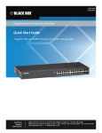
Quick Installation Guide
this document is not up-to-date. Please check with your local
24-port 10/100/1000 Mbps
Layer 2 Managed Switch
with 370W PoE
distributors for the latest information. No part of this document can
be copied or reproduced in any form without written consent from
the company.
Model No.: SP6524P
P/N 2300-0686
WEEE Directive & Product Disposal
At the end its serviceable life ,this product should not be treated
as household or general waste. It should be handed over to the
applicable collection point for the recycling of electrical and
electronic equipment, or returned to the supplier for disposal.
7
w w w . m i c r o n e t . c o m . t w
Introduction
Key Features
Micronet SP6524P 10/100/1000Mbps Managed Switch with 370W
Compliant with IEEE802.3 10Base-T, IEEE802.3u 100Base-TX,
PoE output offers performance and a full set of layer 2 networking
IEEE802.3ab 1000Base-T, and IEEE802.3z
management features at an affordable cost, suitable for high
1000Base-LX/SX standards.
performance workgroups and server applications. With 10/100/1000
Mbps RJ-45 ports and shared mini-GBIC slots for fiber optic
SP6524P provide 24 RJ-45 ports of 10/100/1000Mbps and 4
shared mini-GBIC slots for fiber extension
connection, it delivers maximum throughput to high performance
users or provides a backbone to a growing business network.
Support IEEE 802.3ad Link Aggregation, up to 8 trunk groups, up
to 14 ports for each group.
Support IEEE802.1q tag-based VLAN, IEEE 802.1q-in-q nested
Package Contents
VLAN, and IEEE802.1p traffic prioritization (CoS)
Before you start installing the device, verify the following items are
Support broadcast storm control
in the package:
Support jumbo frame up to 9216K bytes
SP6524P Managed Switch
Support 802.1d STP, 802.1w Rapid STP, IEEE802.1s MSTP
Quick Installation Guide
Support 802.1x port-based authentication and port security with
Manual CD
MAC address
RS-232 cable
Support IGMPV1, IGMPV2, IGMPv3
Mounting Kits & accessories
Support SNMPV1, SNMPV2, SNMPV3
Power Cord
Support IEEE 802.3af PoE support, 15.4W/port at each
of the 24 ports
Support non-standard 30W/port up to 12 ports, configurable in
the web user interface.
1
2
Physical Description
LED definition:
SP6524P
LED
LED
Color Function
SP6524P LED light for port 1-24
System
System Green
On : When the power supplied
to the system
Off : Power off
GE- LED
Link/Act Green
Light: When the link through the
10/100/1000M
port is successfully established.
PoE port
Off : No-link detected for the port
Blink: When the port is activating
Front Panel
transmitting data.
PoE
Amber Light: While PSE supply power.
Off: No PoE power supply to
connected device.
RESET Button:
Rear View
To restore switch configuration to factory defaults
Press the Reset button for more than 10 seconds, switch
configuration will be restored to factory defaults and then reboots.
3
4