1
Control Panels
Table of Contents | en
3
Table of contents
1
Introduction
4
1.1
About documentation
4
1.1.1
Related documentation
4
1.2
Bosch Security Systems, Inc. product manufacturing dates
5
2
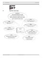
System overview
6
3
Control panel installation
7
3.1
Install the enclosure and wiring label
7
3.2
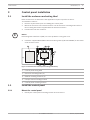
Install the control panel
7
3.2.1
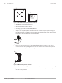
Mount the control panel
7
3.2.2
Connect earth ground
9
3.2.3
Configure OUTPUT A using the jumper
3.3
Control panel to module wiring overview
10
4
Power supply
11
4.1
Primary power terminals
11
4.1.1
Install the transformer
12
4.2
Secondary (DC) power terminals
12
4.2.1
Install the battery
12
4.2.2
Battery maintenance
14
4.2.3
Battery supervision
14
4.2.4
Battery discharge and recharge schedule
14
4.3
B520 Auxiliary Power Supply
15
4.3.1
SDI2 address settings
15
4.3.2
Supervision
15
4.3.3
Auxiliary power supply trouble conditions
15
4.3.4
Installation and control panel wiring (B520)
16
4.3.5
Powered device and battery wiring
17
5
On-board outputs
18
5.1
Powered outputs
18
5.1.1
Circuit protection
18
5.1.2
Total available power
19
5.2
Open collector outputs
19
6
Control panel board overview
20
7
System wiring diagrams
21
7.1
System wiring overview
21
7.2
Battery lead supervision wiring
23
7.3
Notification appliance circuit wiring
23
7.4
Keyswitch wiring
25
7.5
SDI2 devices general system wiring
26
7.5.1
SDI2 bus wiring recommendations
26
7.6
Wiring label
30
8
Specifications
31
8.1
Wire requirements
32
UL Installation Instructions
9
2013.01 | 04 | F01U265448