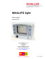
1
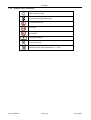
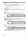
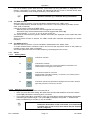
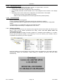
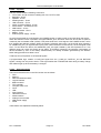
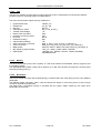
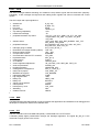
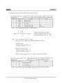
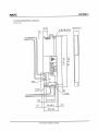
MAGLIFE light Service manual Version 01.00 SCHILLER MEDICAL S.A.S ZAE SUD 4, rue Louis Pasteur BP 90050 F-67162 WISSEMBOURG CEDEX Telephone : +33 (0) 3 88 63 36 00 Fax : +33 (0) 3 88 94 12 82 Internet : http://www.schiller-medical.com E-mail : [email protected] Part : 0-48-0084 MAGLIFE light Record of versions of the service manual Version 01.00 : PN : 0-48-0084 June 2006 Page I June 2006 MAGLIFE light NOTICE This booklet is to be considered as an integral part of the device it describes. This technical manual is intended for qualified staff, and describes the operation, maintenance and trouble-shooting of MAGLIFE light Observation of its contents is an essential condition for correct operation of the device, as well as for the safety of the patient and the operator. The manufacturer rejects any responsibility concerning the safety, reliability and characteristics of the device if: - the assembly, extensions, settings, modifications or repairs have not been carried out by it or by persons authorised by it. - the electrical installation of the corresponding premises is not compliant with the provision in force in the country. - the device is not used in accordance with the instructions for use. - the spare parts have not come from SCHILLER. The booklet corresponds to the device at time of publication. Under no circumstances does provision of this booklet represent authorisation or approval to carry out modifications or repairs on devices. The manufacturer undertakes to provide all spare parts for a period of ten years. All rights are reserved for the devices, circuits, procedures and names mentioned in this booklet. Use of MAGLIFE light is described in the Instructions for Use; any use not specifically described is unforeseen and may present risks. PN : 0-48-0084 Page II June 2006 MAGLIFE light INFORMATION CONCERNING SAFETY • The product bears the mark: CE- 0459 in accordance with the requirements of Council Directive 93/42/EEC concerning medical devices, based on the essential requirements of Annex I of the latter. • It fully satisfies the requirements in terms of electromagnetic compatibility stipulated by standard IEC 60601-1-2 / IEC 60601-2-4 “electromagnetic compatibility of medical electrical equipment”. • In order to guarantee an optimal level of patient safety and electromagnetic compatibility, respect for the specific nature of the measures indicated, and correct operation of the device, we recommend that you use only spare parts from SCHILLER. Any use of accessories other than the original accessories takes places at the exclusive risk of the user. We refuse any responsibility in the event of damage arising from use of incompatible accessories or consumables. • SCHILLER refuses any responsibility concerning the safety, reliability and characteristics if: - the assembly, extensions, settings, modifications or repairs have not been carried out by SCHILLER personnel or by personnel duly authorised by SCHILLER. - the device has not been used in accordance with the instructions for use. • Any use of the device outside the framework of procedures described in the instructions for use takes place at the exclusive risk of the user. • This booklet corresponds to the version of the device and to the technical safety standards in force at the time of publication. All rights are reserved concerning the circuits, procedures, names, software and devices referred to in this technical information booklet. • The quality management system in force at SCHILLER corresponds to international standards ISO 9001 and ISO 13485. • Unless written agreement has been given by SCHILLER, any reproduction of our documentation, in whole or in part, is prohibited. PN : 0-48-0084 Page III June 2006 MAGLIFE light Conventions used in the booklet * Warning : Warns you of an imminent danger. Failure to observe this warning exposes you (and/or those around you) to mortal danger or risk of serious injury. , Caution : Warning describing conditions or actions which may cause malfunction of the device or the software. N.B. : Comment or note of particular interest describing a more effective and more practical operation. ) Additional information or explanation concerning the paragraphs preceding the comment. Manufacturer : SCHILLER MEDICAL 4, rue Louis Pasteur ZAE sud F- 67 162 Wissembourg Tel. Fax : **33 / (0) 3.88.63.36.00 : **33 / (0) 3.88.94.12.82 PN : 0-48-0084 Page IV June 2006 MAGLIFE light CONTENTS 1. Operation _________________________________________________________ 1-1 1.1 1.2 1.3 1.4 2. Display and command elements. ___________________________________________ 1-1 Explanation of symbols used ______________________________________________ 1-4 Operation. _____________________________________________________________ 1-6 Technical specifications __________________________________________________ 1-9 Testing and maintenance _____________________________________________ 2-1 2.1 2.2 2.3 2.4 Functional control _______________________________________________________ 2-1 Oximeter test___________________________________________________________ 2-1 NIBP module test _______________________________________________________ 2-1 Cleaning and disinfection _________________________________________________ 2-2 3. Troubleshooting ____________________________________________________ 3-1 4. Replacement of parts ________________________________________________ 4-1 4.1 Procedure for dismantling the device ________________________________________ 4-2 4.2 Procedure for assembling the device ________________________________________ 4-5 4.3 Replacement of parts ____________________________________________________ 4-5 5. Technical description ________________________________________________ 5-1 5.1 5.2 5.3 5.4 6. Device modifications _________________________________________________ 6-1 6.1 6.2 6.3 6.4 7. Operation of the MAGLIFE light device. ______________________________________ 5-1 The CPU POWER BOARD circuit (WSM0078A) _______________________________ 5-2 The keyboard circuits and USB connection (WSM0079…) ______________________ 5-13 The EXTERIOR ALIM (WSM0081A). _______________________________________ 5-14 Definition ______________________________________________________________ 6-1 The CPU POWER BOARD circuit (WSM0078A) _______________________________ 6-1 The keyboard circuits and USB connection (WSM0079…) _______________________ 6-1 The EXTERIOR ALIM circuit (WSM0081A). ___________________________________ 6-1 Diagrams and layout drawings _________________________________________ 7-1 7.1 7.2 7.3 7.4 7.5 7.6 7.7 General synoptic ________________________________________________________ 7-1 The CPU POWER BOARD circuit (WSM0078A) _______________________________ 7-2 The keyboard circuits and USB connection (WSM0079…) _______________________ 7-3 The EXTERIOR ALIM circuit (WSM0081A). ___________________________________ 7-4 The OEM CPU SPO2 module (3-55-0042) ____________________________________ 7-5 The 6V NIBP module (3-55-0035). __________________________________________ 7-6 The DC/DC CCFL +5V converter (3-55-0042). _________________________________ 7-7 PN : 0-48-0084 Page V June 2006 Operation 1. Operation This chapter describes concise operation of the device. For more detailed use, consult the instructions for use. 1.1 Display and command elements. 1.1.1 Front panel of the MAGLIFE light device 7 8 6 5 9 4 3 10 2 1 11 12 1 : General On/Off button for the device. 7 : Screen for display of curves, parameters, menus and messages. 2 : Device operation light. 8 : Button enabling a blood pressure measure using a cuff to be begun or stopped. 3 : Light indicating that connected to the mains. is 9 : Button for switching on and off the function of (physiological and technical) audio alarm inhibition for 2 minutes or permanently. 4 : Light indicating that the battery is charging. 10 : Button for partial on/off of the device, known as “Standby”. 5 : Button enabling either access to the main menu by display of main menu, or exit out of a menu from any area 11 : Connection socket for the Oximeter fibreoptic sensor. 6 : Rotating menus. socket 12 : Connection measurement cuff. PN : 0-48-0084 button the enabling device selection of Page 1-1 for the NIBP June 2006 Operation 1.1.2 Rear of the MAGLIFE light device 18 13 14 15 16 17 13 : Power supply socket (low voltage cable) 14 : Speaker 15 : USB socket 16 : RS 232 socket 17 : Auxiliary sockets cover 18 : Rating plate PN : 0-48-0084 Page 1-2 June 2006 Operation 1.1.3 Mains power supply 20 19 PN : 0-48-0084 19 : Mains socket 20 : Low voltage cable socket Page 1-3 June 2006 Operation 1.2 Explanation of symbols used 1.2.1 Symbols used on the device. Device On/Off Mains supply present Battery charging Entry to main menu or exit from any menu Reject sound of alarms Non-invasive blood pressure FC device protected against defibrillation shocks (device intended for direct applications on heart). Warning! Consult the instructions for use of this device. Identification symbol for electric and electronic devices. It is compulsory to recycle the parts of the device separately and to send the parts concerned back to the available collection and recycling centres. Inappropriate disposal can cause damage to the environment and to public health, due to the presence of harmful materials in electric and electronic devices. CE certification body. (G-MED) 1.2.2 Symbols used on power supply. Presence of power supply Power supply input point Power supply output point PN : 0-48-0084 Page 1-4 June 2006 Operation 1.2.3 Symbols used on the battery Battery can be recycled. Do not throw into household waste Do not throw onto fire Do not saw Do not break Rechargeable battery Do not short-circuit Unlimited storage at a temperature of 0… +40°C. PN : 0-48-0084 Page 1-5 June 2006 Operation 1.3 Operation. MAGLIFE light is a monitor for surveillance of the vital parameters of a patient, exclusively intended for use during an M.R.I. (Magnetic Resonance Imaging) examination. Depending on the version chosen, MAGLIFE light provides monitoring of the following parameters: - transcutaneous oxygen pulsed arterial saturation (Oximeter). - pulse. - blood pressure (NIBP). MAGLIFE light is intended to be mounted on a mobile non-magnetic base. 1.3.1 Configuration menu The configuration menus are hidden in normal use. Access is initiated by pressing the navigation button (6) during start-up of the device and keeping it pressed down until the appearance of this configuration menu. 1.3.2 Power supply MAGLIFE light is powered through the rear by a power supply module which is connected to the mains. Equipped as standard with a battery, MAGLIFE light can follow the patient during his movements (transfer between the examination room and the adjacent preparation room, for example). ) 1.3.3 N.B. : For use on the 50/60 Hz - 100 V network, the EXTERNAL POWER SUPPLY module is equipped with a specific 100 V transformer. Battery charging The battery charges itself automatically when the device is plugged in, whether off or on. During charging the light (3) flashes, and when the battery is fully charged it remains lit. MAGLIFE light is autonomous under battery power (new condition and fully charged) for two hours (one hour in the case of intensive NIBP use). A warning message is displayed approximately 10 to 5 minutes before automatic shut-down off the device in the event of a dead battery. , 1.3.4 Caution : So as not to damage battery lifespan, never leave it in uncharged condition. In the event of device shutdown due to weak battery, the battery must be recharged as soon as possible. Switching on Plug the mains lead into the socket (19), connect the low voltage cable to sockets (20) and (13). The light (3) comes on, indicating that the device is plugged in. , Caution : light (4) also come on: the battery charges itself automatically when the device is plugged in, even if it is not operating. Press button (1); the related light (2) comes on. After a few seconds, the screen is activated and the system initializes. The initialization sequence lasts about 10 seconds. At the end of this period, the parameters appear. PN : 0-48-0084 Page 1-6 June 2006 Operation For use on battery (mains lead removed), press button (1) only (the battery is integrated in the device). If the battery is correctly charged, the related light (2) also comes on and the device starts up. When the battery is fully charged, autonomy is less than 2 hours. ) N.B. : Operation of button (1) is inhibited during initialization. 1.3.5 The NIBP function When the option is present, it can be activated or deactivated in the " NIBP" menu. To make measurements, activate the option and connect a cuff to the patient (3 possible choices: adult, child or neonatal). Choose the function mode in the NIBP menu: - Manual (each new measurement must be triggered with button (8)). - Continuous (only the first measurement must be triggered with button (8)). - At set intervals : 1; 2; 2.5; 3; 5; 10; 15; 20; 30; 60; 90 min. The results of measurements (systolic / diastolic and mean) are displayed on the screen after each measurement. When the SPO2 function is inactive, the NIBP module also measures and displays the cardiac frequency. 1.3.6 The SPO2 function. When the option is present, it can be activated or deactivated in the "SPO2" menu. To make measurements, activate the option and connect the right SPO2 sensor to the patient (3 possible choices: adult, child or neonatal). The results (saturation level and cardiac frequency) are displayed on the screen. 1.3.7 Alarms 1.3.7.1 alarm symbols 1.3.7.2 S1 Audio alarm activated S2 Audio alarms activated! Displayed when at least one monitoring threshold is deactivated. The technical alarms are triggered none the less. S3 Audio alarms inhibited for 2 minutes. Displayed after button (9) is pressed (< 3 seconds). The remaining time is displayed under the symbol. S4 Audio alarm permanently deactivated. Displayed when the alarm off button (9) is kept pressed for more than 3 seconds. Switching off audio alarm Button (9) enables the audio alarm to be switched off. • When you press the button briefly, the audio alarm remains deactivated for 2 minutes, and the symbol (S3) indicates the remaining time, in minutes. • If you press button (9) for 3 seconds or more, the audio alarm remains permanently deactivated until button (9) is pressed again. The symbol (S4) is displayed, the symbol “∞” flashes and a beep is emitted every 2 minutes, by way of reminder. , PN : 0-48-0084 Caution: Activation / deactivation of the audio alarm. Permanent deactivation of the audio alarm is not authorised in certain sites of use. It is for this reason that the function can be configured. Page 1-7 June 2006 Operation 1.3.7.3 1.3.7.4 Physiological alarms If the value measured exceeds a limit value, an alarm is triggered after 3 secs and • display of the measured value flashes in red, • an intermittent audio alarm is triggered (4 audio signals/sec), • the exceeded parameter window flashes with a red background with reversal of the display colour • depending on the choice made in the configuration, this audio alarm is interrupted: - As soon as its cause is interrupted (not locked). - After its cause has disappeared and button (9) has been pressed (locked) Technical alarms When a technical alarm is triggered: an error message is displayed in the display field for the parameter in question ; an intermittent audio alarm is triggered (2 audio signals), which meets its rejection configuration criteria; a question park (-?-) is displayed in place of the measured value; This alarm stops automatically on disappearance of its cause. 1.3.8 Software upgrading It is imperative that the person who carried out this upgrade must have the skills and authority to be able to carry out the related operational and safety checks, and this person takes full responsibility for these. The software upgrade is carried out using a USB key in accordance with standard 1.1 or higher. Ensure that the software loaded on the USB key in the root directory (this software only) is compatible with the device you wish to upgrade Insert the USB key into socket (15) for this purpose, select the upgrade tab, and loading will begin automatically. Follow the instructions. When loading is complete, the device will shut down automatically. PN : 0-48-0084 Page 1-8 June 2006 Operation 1.4 Technical specifications 1.4.1 System specifications Manufactured by SCHILLER Medical SAS Name of device MAGLIFE light Dimensions main unit power supply 270 x 216 x 116 mm ; 10.6” x 8.5” x 4.6” 180 x 84 x 68 mm ; 7” x 3.3” x 2.7” Weight main unit power supply 6 Kg 1.3Kg Protection class of cover IP 21 Electric power supply 100 ; 115 ; 230 VAC 50/60Hz Voltage is factory-set Input power Fuses Batteries Autonomy Ambient conditions Operation Temperature Relative humidity Pressure Magnetic field Storage Temperature Relative humidity Pressure Magnetic field 25 VA 2x 100 mA (T) @ 230VAC ; 2x 200 mA (T) @ 100-115VAC 12V 2 Ah Lead 2 hours 15°C – 35°C ; 60°F - 96°F 30 – 95% without condensation 500 to 1060hPa ≤ 40mT -10°C – 50°C ; 13°F - 124°F 30 – 95% without condensation 500 to 1060hPa ≤ 40mT Display TFT colour screen; 6.8” ; 98 x 132mm ; 480 x 640 pixels Connections SPO2, NIBP Interfaces RS232, USB 1.1 for connection of equipment specified by SCHILLER Safety standards CEI 60601-1 CEM CEI 60601-1-2 CISPER 11 Class B; with class A printer connected The device can be subjected to the following interferences without being affected: Static discharge up to 8kV Radio frequencies 10V/m (80 – 2500 MHz, 5 Hz modulation) CE marking In accordance with Directives 93/42/EEC class IIb Protection class Class I in accordance with CEI 60601-1 PN : 0-48-0084 Page 1-9 June 2006 Operation 1.4.2 Technical specifications - value reader Pulse Oximeter OEM module BCI Connection Fibre Optic Class CF SPO2 accuracy ± 2 % between 70 and 99 % ± 3 % between 50 and 69 % SPO2 display range 0 – 99% Pulse accuracy 5 b/min Pulse display range 30 – 250 b/min HF Protection protection against electrosurgery devices NIBP – non-invasive blood pressure OEM Module CAS Connection Fast snap Class CF Measurement principle Oscillometric Mode Manual, Automatic, Continuous Types of patients Neonatal, Children, Adults Sensor accuracy ± 3mmHg or ± 2% Pulse accuracy 5 b/min Display range Adult/child : systolic: diastolic: mean: 60 - 250 mmHg 40 - 220 mmHg 45 - 235 mmHg systolic: diastolic: mean: 40 - 130 mmHg 20 - 90 mmHg 35 - 105 mmHg Neonatal : HF Protection PN : 0-48-0084 protection against electrosurgery devices Page 1-10 June 2006 Testing and maintenance 2. Testing and maintenance This chapter describes the test and maintenance procedure recommended for MAGLIFE light. 2.1 Functional control Certain functions are tested automatically by the program. - RAM test, - EPROM test, - CPU test, - ANALOG/DIGITAL converter test. In the event of a problem, a technical alarm message is displayed on the screen. In the event of a communication problem between the monitor’s CPU and the different electronic modules, a technical alarm message ("Time out") is displayed in the window corresponding to the affected parameter. 2.2 Oximeter test - Start up the MAGLIFE light device so that the Oximeter display is shown. - Check that the MAGLIFE light device displays the message "sensor problem". - Connect an SpO2 sensor to the front panel. - Place the SPO2 sensor on your finger and check that the message changes to "pulse search", then after the curve has appeared (approximately 10 secs.) the SPO2 value for SPO2 percentage and B/min pulse should be displayed. Check that an SPO2 curve is shown and that there is a beep for each pulse. 2.3 NIBP module test 2.3.1 NIBP check Connect an NIBP tube with an adult cuff to the front panel connection and choose adult mode. Put on the NIBP cuff and press the NIBP button (8). Check that the NIBP pump motor begins to run and that the cuff begins to inflate. Check that the NIBP screen window begins to indicate an increase in pressure while the cuff begins to inflate. Check that the pump stops when the screen window reads 180mmHg +/- 20mmHg.. The cuff should begin to deflate and after about 20 seconds should display the SYS/DIA/MAP values in the NIBP window. Deactivate the SPO2 function if necessary and check the P/min display. 2.3.2 Calibration of Non-Invasive Blood Pressure - Connect a mercury column and a test cell to the NIBP socket on the front panel of the MAGLIFE light device (if you do not have a test cell, an adult cuff rolled around a bottle in such a way as to have little compliance can be used instead for the purposes of the calibration). - Activate “Calibration” in the NIBP menu; the indication on the screen corresponds to the pressure value measured by the NIBP module. Proceed with the measurement in several points, by comparison of the MAGLIFE light indication and that of the external measurement device, across the whole measurement range. PN : 0-48-0084 Page 2-1 June 2006 Testing and maintenance 2.4 Cleaning and disinfection , Caution : For cleaning, the device must be switched off. Remove all power sources before beginning to clean the device, in order to exclude any risk of accidental start-up of the device. Before cleaning, also unplug the sensor cables. No liquid must penetrate into the device; should this happen, however, the device must only be reused after aftersales service verification. You are formally advised not to clean the devices with products such as ether, acetone, esters, aromatic products, etc. Never use phenol-based cleaning products or products containing peroxide derivatives to disinfect the surfaces of the device case. • Before cleaning the sensor electrode cables, disconnect them from the device. In order to clean and disinfect them, wipe them using a gauze cloth soaked in cleaning fluid or disinfectant. Never emerge the connectors in liquid. As a cleaning solution, you can use any cleaning or disinfectant solution used in hospital environments. • Proceed in the same way with the device case, using a cloth lightly soaked in cleaning fluid or disinfectant. No liquid must penetrate into the device during this operation. PN : 0-48-0084 Page 2-2 June 2006 Troubleshooting 3. Troubleshooting This chapter describes the tracking of breakdowns in the event of MAGLIFE light malfunctioning. If the tracking or correction of the fault poses a problem, contact SCHILLER After-Sales Service. ) N.B. : When there is an error message, before any intervention note the error number and restart the device to check that it is not simply the result of a crashed program. ) N.B. : Before any intervention, check if all 13 chevrons on the CPU are short-circuited. ERROR OBSERVATION Screen is black but menus and messages are displayed Screen is very dark Screen interference USB does not work Rotating button does not work Speaker does not work POSSIBLE CAUSES 1. Microcontroller on CPU board not working. 1. Problem with backlighting connection. 2. Problem on the backlighting board 1. Problem with ribbon cable connection. 2. Ribbon cable not working 1. Problem in the USB cable. 2. Problem with F1000 fuse on CPU board. 1. Problem in the button cable. 1. Problem with the speaker cable. 2. Problem with CORRECTIVE ACTIONS 1. Replace the microcontroller 1. Check the backlighting cables. 2. Replace the backlighting board 1. Reposition the ribbon cable in the connector. 2. Replace the ribbon cable. 1. Check the contacts in the USB cable. 2. Replace the F1000 fuse. 1. Check the contacts in the button cable. 1. Check the contacts in the HP cable 2. Replace the microcontroller µcontroller buzzer on CPU board Device works on battery and shuts down shortly after starting up PN : 0-48-0084 1. Battery charge is low 2. Battery not working Page 3-1 1. Recharge for 10 hrs. 2. Replace the battery June 2006 Troubleshooting ERROR OBSERVATION POSSIBLE CAUSES The device is powered with the battery, but will not start. 1. Problem with F100 fuse on CPU board. 2. Battery not working 3. CPU board not working 1. Problem with F1900 fuse on CPU board. 2. Battery not working 3. CP board not working The battery does not charge when the mains is connected The " charge battery " LED stays off CORRECTIVE ACTIONS 1. Replace the F100 fuse. 2. Replace the battery. 3. Replace the CPU board 1. Replace the F1900 fuse. 2. Replace the battery. 3. Replace the CPU board ERROR MESSAGES "Time out" error (in the SPO2 window) "Time out" error (in the NIBP window) PN : 0-48-0084 1. Problem on the SPO2 board 1. Problem on the NIBP board Page 3-2 1. Replace the SPO2 board 1. Replace the NIBP board June 2006 Replacement of parts 4. Replacement of parts This chapter describes the dismantling of the MAGLIFE light device in order to replace faulty parts. The following warnings apply to any intervention inside the device. , Caution : Before dismantling the device, remove all power supply sources , Caution : The device contains circuits which are sensitive to electrostatic discharge. Any MAGLIFE light intervention must be carried out with respect for ESD usage regulations. The intervention must be performed on an earthed, antistatic mat, and the operator must wear an anti-static bracelet which is also earthed. , Caution : A general test of the device must be conducted after every opening of the device. PN : 0-48-0084 Page 4-1 June 2006 Replacement of parts 4.1 Procedure for dismantling the device 4.1.1 Opening the device Unscrew the 8 screws. Separate the two parts of the casing and disconnect the 5 cables indicated below. PN : 0-48-0084 Page 4-2 June 2006 Replacement of parts 4.1.2 Removal of CPU sub-system + screen Take out the MENU button. Disconnect the cables from the SPO2 base and the tube from the NIBP. Unscrew the 8 screws, then extract the sub-system. PN : 0-48-0084 Page 4-3 June 2006 Replacement of parts Photos of the sub-system without the SPO2 and NIBP modules: PN : 0-48-0084 Page 4-4 June 2006 Replacement of parts 4.2 Procedure for assembling the device For assembly of the device, operate in reverse fashion to the dismantling procedure. , 4.3 Caution : The cables must be positioned properly to avoid jamming them during assembly. Replacement of parts * Warning : The replacement of parts must only be carried out by personnel who are specially trained and authorised by SCHILLER. Furthermore, all replacement parts must originate from SCHILLER. ) PN : 0-48-0084 N.B. : To order a new part from SCHILLER, give the device type and serial number located on the rear of the device. Next, specify the article code for the part to be replaced. Page 4-5 June 2006 Replacement of parts PN : 0-48-0084 Page 4-6 June2006 Replacement of parts PN : 0-48-0084 Page 4-7 June2006 Replacing parts Appearance of the subsets REF. PN 7 3-10-0119 9 3-10-0122 36 3-10-0116 56 3-10-0112 66 3-10-0117 APPEARANCE OF THE PART VDC power supply cable, PN 3-10-0118. PN : 0-48-0084 Page 4-8 June 2006 Replacing parts Mains power supply A B C D E F G REF QTY PN A B C D E F G 1 1 1 1* 1 1 1 4-21-0150 3-10-0121 6-02-0042 3-10-0124 WSM0081A 3-10-0113 3-10-0120 PLAN No. PCIND0747 W3M144376 PCIND0752 PCIND0739 PCIND0746 DESCRIPTION Mains connector Earth cable Power supply case version 2 Cavalier cable transformer IC power supply VDC output cable Phase / neutral cable (*) QTY 2 for 115 V mains wiring (see § 5.4.2). PN : 0-48-0084 Page 4-9 June 2006 Description technique 5. Technical description 5.1 Operation of the MAGLIFE light device. 5.1.1 General information: The MAGLIFE light device comprises the following elements: The CPU POWER-board comprising a CPU section, a POWER section and all the connections required for access to the different elements of control, communication, signalling and visualisation. The board also supports and manages the SPO2 (OEM) and NIBP (OEM) options. The CPU provides the digital and analog processing of MAGLIFE light and the POWER section supplies the different power supplies required for the device to operate. All connections between the CPU section and the POWER section flow through chevrons. They enable the CPU section to be electrically isolated from the POWER section during testing of the latter. These connection lines are shunted through the POWER section, before the chevrons, on a test connector. N.B. : In normal monitoring mode, all chevrons are closed. Keyboard circuits which serve as an interface between user and device. A screen on which the curves and different parameters can be displayed. The MAGLIFE light power source can be provided by a mains power supply module through a connector located at the rear of the device and/or a battery permanently mounted in the device. The battery is rechargeable through the power supply, and a light on the front panel indicates when this is taking place. PN : 0-48-0084 Page 5-1 June 2006 Description technique 5.2 The CPU POWER BOARD circuit (WSM0078A) 5.2.1 The power supply section: 5.2.1.1 Presentation The power supply section of MAGLIFE light delivers, from the mains power supply modules or from the lead 12 V–2Ah battery permanently mounted in the device, the following voltages: U_MAINS U_ALIM +3.3V_TEST +5V_TEST +6V_TEST EVER_VCC U_BAT It also charges the battery, from the voltage delivered by the mains power supply module through the battery charger. Monitoring of battery charge status is provided by a system of comparators which deliver the signals BATFULL_TEST, I_LOAD_TEST and –BAT_LOW_TEST. The signals BATFULL_TEST and I_LOAD_TEST are used in combination to acknowledge the completion of battery charging. The signal –BAT_LOW_TEST also acts on the On/Off status of the power supply. It switches off the device hardware. This takes place when battery voltage is below 10 V. In parallel to the surveillance by the system of comparators, battery voltage is continuously monitored by means of the ADC of the CPU section. Power supply On/Off control is under the control of the CPU section by means of the signals M/A_TEST and -HB0_TEST. They control establishment of the U_ALIM, +3.3V_TEST, +5V_TEST, +6V_TEST and U_HALL_TEST voltages and activation of the battery charger. The EVER_VCC voltage is always present. It only depends on the presence of one of the power sources; mains power supply module or battery. The protection fuse of the MAINS power supply is located in the mains power supply module, while that of the battery is located on the CPU POWER-board. 5.2.1.2 Description of the input stage: The power supply input of the device is protected against polarity reversal. This is carried out by means of D1800. The output of this diode delivers the U_MAINS voltage, from which the battery charger is supplied. It also supplies, via D1805, the DC/DC converter which produces the EVER_VCC power supply voltage. In addition, it is also used as a control signal acting at the level of U_HALL_TEST voltage command, and control of the power supply for the battery monitoring system (U1801 and U1803). The common point formed by the D1801 and D1802 cathodes delivers the COM_PWR voltage which results from the U_MAINS and U_BAT voltage. The amplitude range of this voltage, according to the power sources in place (mains power supply module or battery), can vary between 32 V and 9.5 V. This is the voltage from which the U_ALIM switched power supply voltage is produced which supplies the +3.3 V, +5 V and +6 V DC/DC converters. It is also the voltage from which is produced the switched power supply voltage COM_PWR_CTRLD which supplies the battery monitoring system. Similarly, the common point formed by the D1805 and D1807 cathodes delivers the IN_STARTUP voltage which is resultant from the U_MAINS and U_BAT voltages. This voltage supplies the DC/DC EVER_VCC converter. PN : 0-48-0084 Page 5-2 June 2006 Description technique Synoptic of the power supply section U_MAINS U_MAINS_CPU U_ALIM U_ALIM_CPU +3.3V_TEST +3.3V +5V_TEST +5V +6V_TEST +6V I_LOAD_TEST I_LOAD_5V EVER_VCC EVER_VCC_CPU U_HALL_TEST U_HALL -HB0_TEST -HB0 M/-A_TEST M/-A -BAT_LOW_TEST -BAT_LOW_TEST -BAT_LOW_5V BATFULL_TEST BATFULL_TEST BATFULL_5V U_BAT U_BAT U_BAT_CPU Q1800 MAINS U_MAINS D1800 DC / DC CONVERTER COM_PWR U_ALIM 3.3 V CPU and LCD POWER SUPPLY D1801 DC / DC CONVERTER 5V GND BACKLIGHT and AUXILIARY POWER D1802 DC / DC CONVERTER 6V NIBP and AUXILIARY POWER BATTERY U_MAINS CHARGER OUT_LOADER D1805 D1806 IN_STARTUP DC / DC U_HALL EVER_VCC ON/-OFF_UHALL D1807 D1804 D1808 - D1812 U_BAT U_MAINS BATTERY SUPERVISORY U_ALIM_ON ON/OFF CONTROL 1 Lead-Acid Battery 12V - 2Ah 2 TO TEST CONNECTOR GND PN : 0-48-0084 Page 5-3 June 2006 Technical description of the boards 5.2.1.3 Control of power supply voltages activation: Switching of the U_ALIM voltage, from which are also produced the +3.3V_TEST, +5V_TEST and +6V_TEST voltages, is carried out by means of the Q1800 switching transistor. It is controlled by the U_ALIM_ON signal resulting from the logical operation carried out from the command signals M/-A_TEST, HB0_TEST and status signal –BAT_LOW_TEST. The signal –HB0_TEST, active low, cuts the power supply voltages when an excessive ambient magnetic field has been detected. Similarly, the signal –BAT_LOW_TEST active low cuts the power supply voltages when the battery voltage falls below 10 V. The table below summarises the status of the switching transistor depending on the command and status signals. Control of power supply voltages activation M/-A_TEST 0 0 0 0 1 1 1 1 -HB0_TEST 0 0 1 1 0 0 1 1 -BAT_LOW_TEST 0 1 0 1 0 1 0 1 Q1800 Status Off Off Off Off Off Off Off On 5.2.1.4 Power supply voltage +3.3V_TEST : The power supply voltage +3.3V_TEST is produced from the U_ALIM voltage, by means of a DC/DC down converter built around U2000. It delivers a regulated voltage of +3.3 V +/- 5% and can provide a current of 1.5 A. Activation of this voltage is controlled by the signal U_ALIM_ON. 5.2.1.5 Power supply voltage +5V_TEST : The power supply voltage +5V_TEST is produced from the U_ALIM voltage, by means of a DC/DC down converter built around U2001. It delivers a regulated voltage of +5 V +/- 5% and can provide a current of 1.2 A. Activation of this voltage is controlled by the signal U_ALIM_ON. 5.2.1.6 Power supply voltage +6V_TEST : The power supply voltage +6V_TEST is produced from the U_ALIM voltage by means of a DC/DC down converter built around U2100. It delivers a regulated voltage of +6V +/- 5% and can provide a current of 1.2 A. Activation of this voltage is controlled by the signal U_ALIM_ON. 5.2.1.7 Power supply voltage EVER_VCC : The power supply voltage EVER_VCC is produced from the IN_STARTUP voltage, by means of a DC/DC down converter built around U1903. It delivers a regulated voltage of +6 V +/-10% and can provide a current of 300 mA. The presence of this voltage is directly linked to the presence of the device’s power supply sources (mains power supply module and/or battery). It is not switched. The EVER_VCC voltage mainly supplies the device’s On/Off circuit and the ambient magnetic field measurement circuits. 5.2.1.8 Battery charger: The battery charger comprises a DC/DC down converter built around U1900, a U1901 charge current measurement circuit and a U1902 end-of-charge detector. It is powered from U_MAINS, which is the voltage delivered by the mains power supply module. Its activation is controlled by the signal –HB0_TEST which commands shutdown of the charger when the device enters an excessive magnetic field. It delivers a voltage of 14 V and has a charge current limitation of 250 mA. The charge current measurement is carried out across resistors equivalent to 0.5 Ω, R1907 and R1908, inserted into the charger’s output line. The voltage developed on the terminals of the measurement resistor is applied to the U1901 amplifier circuit. This delivers a voltage, amplified by plus 50, which is proportional to the battery charge current. This is applied to the U1902B comparator, which has a transfer threshold set at 0.9, corresponding to a charge current of 18 mA. When this threshold is reached, the signal I_LOAD_TEST passes to low status. In combination with the signal BATFULL_TEST, the signal I_LOAD_TEST controls the battery charge indication light. The table below gives the indication light status in accordance with the status of the signals I_LOAD_TEST and BATFULL_TEST. PN : 0-48-0084 Page 5-4 June 2006 Technical description of the boards I_LOAD_TEST BATFULL_TEST Status of battery charge indication light 0 0 1 1 0 1 0 1 Lit Flashing Flashing The outlet of the OUT_LOADER charger is equipped with protective elements, F1900 and D1806, intended to protect the battery against an excessive charge current and to prevent battery voltage return on the U1900 DC/DC converter outlet when the U_MAINS voltage is not present. The F100 fuse placed at the outlet of the battery provides overall protection for the latter from the CPU POWER-board. 5.2.1.9 Battery voltage monitoring: Battery voltage monitoring is carried out by a system of threshold comparators which delivers the BATFULL_TEST and –BAT_LOW_TEST status signals. The system of comparators is powered by a switched voltage COM_PWR_CTRLD. It is switched by the Q1806 transistor which is controlled by the U_ALIM_ON signal and/or the presence of the MAINS voltage. Similarly, the connection between the battery and the system of comparators is controlled by the Q1804 transistor. The aim of this management system is to control leakage currents drawn from the battery when the device is switched off and the mains power supply module unplugged. The battery voltage is applied to the divider comprised of R1811 and R1814 which provide a reduction of 4.32. The resulting signal is then applied to the inlet of the U1803B and U1803A comparators by means of R1813 and R1819 resistors. These, in combination with R1809 and R1817, give hysteresis to the BATFULL_TEST and –BAT_LOW_TEST comparators. The switching thresholds of the comparators are carried out from the VREF_PWR voltage delivered by U1801B and U1802. The voltage amplitude of the BATFULL_TEST and –BAT_LOW_TEST comparator outputs are limited to EVER_VCC voltage using clipping diodes D1810 and D1811. The signals generated by the comparators are exploited by the CPU section of the board. However, the signal –BAT_LOW_TEST also acts at On/Off level by means of U1804. It causes switch-off of the device hardware when battery voltage falls below 10 V. ) PN : 0-48-0084 N.B. : Hardware switch-off is the final level of device shutdown. Under normal operation, device shutdown due to low battery is controlled by the CPU section. It is achieved by monitoring of battery voltage via the ADC. It takes place at 10.5 V. So as not to damage battery lifespan, never leave it in uncharged condition. In the event of device shutdown due to weak battery, the battery must be recharged as soon as possible. Page 5-5 June 2006 Technical description of the boards 5.2.2 The CPU section The CPU section contains the operating system (Linux), all associated specifications, keyboard management and display, management of signals coming from the sensors (SPO2, NIBP, Hall) and management of all inputs/outputs (peripherals). It is comprised of a Coldfire microprocessor, memory (RAM and flash) and peripherals such as the USB, the TFT controller, the clock (RTC), the sound (Buzzer) and serial connections. A programmable component (CPLD) is used for address decoding (selection of correct peripheral), generation of reset signals and certain control signals, and management of the keyboard and the rotating button. An analog micro-controller (ANA) enables management of the SPO2 and NIBP sensor signals and communication of the results to Coldfire. The possible configurations are the use of an Oximeter and/or a sphygmomanometer. 5.2.2.1 Organigram Memory : -Flash -RAM BDM Coldfire CPU Peripherals : Compact Flash RS232 USB TFT CPLD RTC Data buffers Keyboard RS232 Hall POWER UART ANA - TEST BUZZER CAS BCI ANA NIBP TEST SPO2 UART uC ANA PN : 0-48-0084 Page 5-6 June 2006 Technical description of the boards 5.2.2.2 Top level The CPU board holds the following connectors: • TFT screen: JP100 connector enabling use of a 6"5 TFT screen • Backlight : JP102 • Speaker : JP103 • Rotating button : JP104 • USB connector : JP112 • Serial connection RS232 : JP105 • SPO2 sensor : JP108 and JP109 • NIBP sensor : JP107 • Keyboard board : JP101 • Battery : P101 • External power supply : JP106 An on/off circuit sends an on/off signal to the POWER section in order to start up and shut down the device: When the ON/OFF button is pressed, the signal ON/OFF_BUT becomes active low and a 200 ms pulse is created by the monostable 4538 (U100A). This pulse sends a 5V on/off signal to the POWER section, which then supplies the different voltages. When the board is powered, after reset, it is the CPLD which creates a 5V –MONITOR_OFF_5V signal to take up the pulse. When the device is switched on, the on/off signal is still at 5V. To shut down the device, the–MONITOR_OFF_5V signal created by the CPLD passes to 0V. Two different cases can cause this switch to low status: A stoppage created by the software (confirmation of device shutdown by user or low battery measurement) or a safety shutdown generated by the ON/OFF button being pressed for at least 4 secs. T filters (R-C-R) are present on all external signals. A programmable logic creates a LOAD_ON signal from the I_LOAD_5V, BATFULL_5V and BATLOW signals, coming from the power section. This signal makes the LOADING led flash during a battery charge and makes it light up when the battery is charged. 5.2.2.3 Interconnections The interconnected blocks on the CPU section are as follows: • CPU • Memory • Data and address buffers • Logical interface • BDM connector • TFT controller • Compact Flash card • Clock • USB • Sound section • Hall effect sensors • Serial interface • Analog microcontroller • NIBP power supply • SPO2 These blocks are explained individually below. PN : 0-48-0084 Page 5-7 June 2006 Technical description of the boards 5.2.2.4 CPU The CPU is a Coldfire microprocessor made by Motorola, and it is responsible for executing the different programs (start-up, operating system and applications). The main communication signals used by Coldfire are: • • • • • • • • • • • • • • • general board reset address bus data bus interrupts from CPLD Transfer Acknowledge flash access chip select periphery access chip select bus clock read/write (writing) output enable (reading) serial connection 0 (console) serial connection 1 BDM signals IDE signals (Compact Flash) RAM signals 5.2.2.5 -RESET_CF CF_A[1..25] D[0..31] NT_H, INT_M, INT_L -TA CS0 CS1 BCLK RW -OE RXD_0, TXD_0, CTS_0, RTS_0, -INVALID_0 RXD_232, TXD_232, CTS_232, RTS_232, -INVALID_1 PSTCLK, DSCLK, -BKPT, DSI, DSO, PST[0..3], DDATA[0..3] -RST_CF, -IORD, -IOWR, IORDY, BUFEN2 -SDRAM_CS1, -SDRAS, -SDCAS, -SDWE, SDUDQM, SDLDQM, BCLKE Memory The flash AM29LV320 (U401) has a capacity of 4 Mb, and contains the bootloader (start-up program) and the operating system. The SDRAM MT48LC16M16 (U400) has a capacity of 32 Mb, and contains the programs currently being executed (working memory). 5.2.2.6 Bus buffers The CPU accesses the flash and the RAM directly, but data buffers are used during access to the different peripherals. The address buffers 74LCX541 (U501, U502 and U503) are always on and mainly serve to drive enough current for the different peripherals. The data buffer 74LCX16245 (U500) is activated with the signal –PERI created by the CPLD when peripherals are accessed. PN : 0-48-0084 Page 5-8 June 2006 Technical description of the boards 5.2.2.7 CPLD The CPLD manages address decoding and creates the Chip Select signals which activate each periphery individually. It also manages the keyboard and rotating button signals and various command and control signals. The CPLD input and output signals are: • • • • • • • address bus data bus bus clock general reset chip select (peripherals) transfer acknowledge peripheral elements chip select • element resets • peripheral interrupts • • • • • • • • • • • • • • • • • • • • • • • • interrupts going to coldfire Read-Write and Output Enable (coldfire) Read and Write (CPLD) Compact flash access Communication with the TFT controller keyboard buttons rotating button on off button screen brightness adjustment audio amp activation backlight activation rotating button management UART clock (output) BUZZER clock (input) interlocked NIBP pump high magnetic field battery low battery full charge current present mains present low frequency clock Watchdog Coldfire reset out 5.2.2.8 B_A[1..23] B_D[24..31] BCLK -RESET_CF -CS1 -TA -CS_CF1, -CS_CF2, -PERI, -CS_TFT, -CS_ADC, -CS_BUZZER, -CS_ANA, -CS_TEST, CS_RTC, -CS_USB -RST_USB, -RST_ADC, RST_BUZZER, -RST_TFT, RST_UART, -RST_MEM INT_BUZZER, -INT_ADC, INT_USB, -INT_RTC, INT_ANA, INT_TEST, INT_CF INT_H, INT_M, INT_L RW, -OE -RD_, -WR_ BUFENB2 TFT_RDY KEY_f[0..3] PUSH_f ON/OFF_BUTf -BL_ON, BRT_UnD, -BRT_INC, -BRT_CS SOUND_ON nMONITOR_OFF ROT_A_f, ROT_B_f CLK_UART_CF CLK_BUZZER, PUMP -HB0 nBAT_LOW BATFULL I_LOAD MAINS CLK_LOW WDI nRSTO BDM The BDM (Background Debug Mode) connector enables the applications and hardware to be debugged and developed. It will also be used for the hardware tests. 5.2.2.9 TFT The TFT controller used is the SED1386 (U800). It sends data to a 6"5 TFT screen. A DS1804 (U803) digital potentiometer changes the backlight brightness. The signal BL_ON_5V is the command to supply power to the screen. PN : 0-48-0084 Page 5-9 June 2006 Technical description of the boards 5.2.2.10 Compact Flash Compact Flash is a memory containing the applications, configurations (options) and trends. It acts as the hard disk. 5.2.2.11 RTC A battery-powered DS1501 (U1000) RTC (Real Time Clock) keeps the time on the device. 5.2.2.12 USB The SL811 (U1100) USB controller enables implementation of a USB output to connect to a USB key or, potentially, to connect a printer. 5.2.2.13 Audio Alarms are generated by an AT89C2051 (U1201) microcontroller. A serial communication transmits a frequency and an amplitude to this microcontroller. The corresponding frequency is generated through a P1 serial port, and the sinusoid is smoothed out using resistors. The amplitude of the resulting signal is changed using a DS1804 (U1203) digital potentiometer. The U1202B operational amplifier generates a virtual mass. The signal is finally transmitted to a TDA1905 (U1200) audio amplifier which provides the necessary power. 5.2.2.14 Hall sensors Magnetic field measurement is carried out from a very precise voltage. A P1300 potentiometer enables the output voltage of the LT1761 (U1300) regulator to be set at 5V +/-0.1%. Using a divider, two voltages, of 1.25 V and 3.75 V, are created and used as upper and lower thresholds for the magnetic field measurement. These thresholds correspond to a field of –40 mT and 40 mT. If these thresholds are crossed in one of the three field measurement directions, the signal –HB0 (active low) is generated, followed by abrupt device shutdown. A MAX1295 (U1304) analog digital converter measures the magnetic field in the three directions. It also measures battery voltage status, 6V and VCC voltage. For the field measurement, the ADC input voltage has simply been divided by 2 (reference of 2.5 V). For the battery voltage measurement, the ADC input voltage corresponds to the formula Vbat/k = Vbat/3 - 2.5. 5.2.2.15 UART A UART TL16C754 (U1401) quad serves as a 3-serial-connection interface with the ANA microcontroller, the buzzer and a test connector. 74LVX3245 (U1400 and U1402) tension transceivers are used as an interface between the 3.3 V and 5V logical levels of certain signals. 5.2.2.16 Analog CPU A AT89C51 (U1502) microcontroller manages communication between the SPO2 and NIBP sensors and the microprocessor. To do so, it is interfaced with a UART (U1500) quad, and uses a demultiplexer (U1503) to generate the Chip Select signals. A voltage supervisor (U1504) generates the start-up reset which initializes all the components. PN : 0-48-0084 Page 5-10 June 2006 Technical description of the boards 5.2.2.17 NIBP power supply For the NIBP measurement, we use a CAS module. Activation of the NIBP signal _ON_5V leads to generation of the +6V_CAS voltage. The signal PUMP_5V is generated when the current consumed on the +6V_CAS voltage is high. 5.2.2.18 SPO2 For the SPO2 measurement, we use a BCI module. The analog +5Va and –5Va voltages are realised using MAX1735 (U1702) and MAX883 (U1703) voltage regulators and a 7662 (U1701) voltage converter. The U1700A and U1700B amplifiers amplify the input signals coming from the sensors. The two connectors JP1700 and JP1701 are the connections to the BCI module. PN : 0-48-0084 Page 5-11 June 2006 Technical description of the boards 5.2.2.19 The connectors: Test alim TFT screen ROT Keyboard MAINS TFT BAT BDM RS232 USB HP ALIM SPO2 Module CPU Compact Flash CPLD NIBP SPO2 sensors Analog Test 5.2.2.20 The components: Ever_Vcc converter 5V converter 6V converter 3V3 converter Battery charger TFT Audio amp USB flash RAM UART CPLD Coldfire UART analog microcontroller PN : 0-48-0084 Page 5-12 BUZZER microcontroller June 2006 Technical description of the boards 5.3 The keyboard circuits and USB connection (WSM0079…) The three circuits are part of the same flank. When these circuits are separated, a code article is attributed to each of them. These codes are as follows: - IC CLAVIER G. MAGLIFE LIGHT (CA : WSM0079B). [Left keyboard circuit] - IC CLAVIER D. MAGLIFE LIGHT (CA : WSM0079C). [Right keyboard circuit] - IC CONNEXION USB MAGLIFE LIGHT (CA : WSM0079D). [USB connection] 5.3.1 The left keyboard circuit This has three push buttons, the actions of which are transmitted to the CPU via a 16P flat cable connection. These three push buttons control the following functions : - On/Off for a blood pressure measurement by cuff. - Starting and stopping the audio alarms inhibition function (physiological and technical alarms). - Partial On/Off of the device, known as “Standby”. 5.3.2 The right keyboard circuit This has two push buttons which control the following functions: - General On/Off of the device. - Access to the main menu. It also has the following three indication lights : - Device operating light. - Light indicating that the device is connected to the mains. - Light indicating that the battery is charging. All this information is sent via a 10P flat cable to the left keyboard and then to the CPU via the 16P flat cable. 5.3.3 The USB connection circuit. This supports the USB connector and enables the USB plug to be attached to the rear of the device. This circuit also contains pins which enable easy soldering of the cable connecting the USB to the CPU. PN : 0-48-0084 Page 5-13 June 2006 Technical description of the boards 5.4 The EXTERIOR ALIM (WSM0081A). 5.4.1 GENERAL INFORMATION: The mains power supply module delivers, from the 50-60 Hz network, a rectified and filtered voltage (MAINS) which may vary, according to the current output, between 18 V and 32 V. It is designed to operate on 115 V and 230 V networks using a voltage selector integrated into the module board. The power conversion is performed using a 25 VA toroidal transformer with double windings, primary and secondary. ) N.B. : For use on the 50/60 Hz - 100 V network, the EXTERIOR ALIM module is equipped with a specific 100 V transformer. 5.4.2 DESCRIPTION OF THE POWER SUPPLY: The mains socket of the module incorporates EMI filters and fuse compartments. For operations on the 115 Vrms network, the value of the fuses is 200 mAT. For operations on the 230 Vrms network, the value of the fuses is 100 mAT. The voltage selector is composed of four FASTON configuration cable terminals JP4, JP5, JP6, JP7. The module is configured for use on 230 V mains when cable terminals JP5, JP6 are connected together. It is configured for use on 115 V mains when cable terminals JP4, JP6 are connected together and cable terminals JP5, JP7 are connected together. 3-10-0124 230 V version Place 2 100 mAT fuses in the compartment provided in the mains base 3-10-0124 115 V version Place 2 200 mAT fuses in the compartment provided in the mains base A thermo-fuse integrated into the transformer provides protection for it against excessive heating. It acts directly at the level of the primary by opening the power supply line. The voltage delivered by the transformer secondary is double-alternation rectified by D1, D2, D3, D4 and filtered by C3, C4. The R1, R3 resistors constitute a limitation of the input current of the C3, C4 capacitors when the module is switched on. As the filter capacitor terminals voltage increases, the Q2 transistor moves towards saturation and makes the Q1 transistor conductive. In this state, the MAINS output voltage is fully operational. Another PN : 0-48-0084 Page 5-14 June 2006 Technical description of the boards protection, constituted by the CTP R11, protects the limitation resistors R1, R3 against overheating in the event of short-circuiting of the filter capacitors. In addition, the MAINS output voltage is equipped with a system for rapid discharge of filter capacitors C3, C4. Its aim is to prevent prolonged presence of MAINS voltage on the module output. While the module is under voltage, the signal taken from the D2 cathode blocks the Q3 transistor. In the absence of secondary voltage, the Q3 transistor is on and the filter capacitors are discharged through R7, R12. PN : 0-48-0084 Page 5-15 June 2006 Device modifications 6. Device modifications 6.1 Definition ECL: The ECL is the board modification index. There are two types of ECL numbering: - the first has three figures (PNN). -P : corresponds to the board version number and is incremented on each rerouting. - NN : is incremented for each modification carried out on the board. NN falls back to 00 when the P version varies. - the second has 2 letters (PN) of the board 6.2 6.3 6.4 -P : corresponds to the board version number and is incremented on each rerouting. -N : is incremented for each modification carried out on the board. NN falls back to A when the P version varies. The CPU POWER BOARD circuit (WSM0078A) Article code ECL WSM00078A WSM00078A 100 101 Modifications 1st version of the board Modification 06.059.003, change of value from R1919 → 30.1 k. The keyboard circuits and USB connection (WSM0079…) Article code ECL WSM0079B WSM0079C WSM0079D 100 Modifications 1st version of the boards The EXTERIOR ALIM circuit (WSM0081A). Article code ECL WSM0081A 100 PN : 0-48-0084 Modifications 1st version of the board Page 6-1 June 2006 Diagrams and layout drawings 7. Diagrams and layout drawings 7.1 General synoptic PN : 0-48-0084 7-1 June 2006 WSM0078 Maglight CPU-POWER BOARD CPU 3-10-0116 1 2 3 4 USB JP112 1 2 3 4 5 CON4 11 CON5 1 6 2 7 3 8 4 9 5 JP? CN M 9 C SOUD SUB D/CAVE 1 V_USB DD+ GND CAVE CON5 1 2 3 4 5 6 7 8 9 10 3-10-0117 1 2 3 4 5 6 7 8 9 10 RXD_232 RTS_232 TXD_232 CTS_232 1 2 1 2 CON2 M/-A -HB0 I_LOAD BATFULL -BAT_LOW JP106 GND R1834 R1835 R1836 R1837 LOAD_ON ON/OFF_BUT TP_CPLD VCC LOAD_ON ON/OFF_BUT TP_CPLD VCC CAVE GND_HALL GND_SPO2 GND BZ1 3-10-0112 3-10-0111 BATTERY P101 GND VBAT1 EXT_DC GND UBAT1 CON2 3-10-0110 1 2 3 Connection to external DC GND CON10 CAVE GND_HALL GND_SPO2 GND JP103 1 2 1 2 CON2 SPEAKER_1 SPEAKER_2 2 Buzzer +3.3V +5V +6V EVER_VCC U_ALIM U_HALL U_MAINS U_BAT CH1808 CH1809 CH1810 CH1811 CH1812 M/-A -HB0 I_LOAD BATFULL -BAT_LOW JP105 10 RS232 1 2 3 4 5 POWER CH1800 CH1801 CH1802 CH1803 CH1804 CH1805 CH1806 CH1807 +3.3V +5V +6V EVER_VCC U_ALIM U_HALL U_MAINS U_BAT BUZZER MURATA PKB24SPC-3601 3-10-0122 Rot - Push Turn Button JP104 1 2 3 4 5 Push Button 1 2 3 4 5 CON5 KEYBOARD_L 4-15-0024 JP2 1 2 3 4 5 6 7 8 9 10 1 2 3 4 5 6 7 8 9 10 GND GND LOAD_ON_5V U_MAINS_5V M/-A GND GND ON/OFF_BUT KEY_0 KEY_1 KEY_2 KEY_3 GND GND GND KEY_1 KEY_2 KEY_3 GND GND CON10 R1_A GND_SPO2 GND_SPO2 E1_SPO2 E2_SPO2 GND_SPO2 JP101 1 2 3 4 5 6 7 8 9 10 11 12 13 14 15 16 1 2 3 4 5 6 7 8 9 10 11 12 13 14 15 16 CON16 SPO2_BCI JP1701 R2_A CON5 4-15-0023 KEYBOARD_R JP3 GND GND LOAD_ON_5V U_MAINS_5V M/-A GND GND ON/OFF_BUT KEY_0 KEY_1 KEY_2 KEY_3 GND 1 2 3 4 5 6 7 8 9 10 1 2 3 4 5 6 7 8 9 10 CON10 JP1700 GND_SPO2 GND_SPO2 -RST_SPO2_5V GND_SPO2 -5Va TXD_SPO2 RXD_SPO2 +5Va GND_SPO2 +5Vd GND_SPO2 1 2 3 4 5 6 7 8 9 10 11 12 13 14 CON14 R2_A R1_A GND_SPO2 GND_SPO2 E1_SPO2 E2_SPO2 GND_SPO2 CON10 1 2 3 4 5 6 7 8 9 10 11 12 13 14 CON16 GND_SPO2 GND_SPO2 -RST_SPO2_5V GND_SPO2 -5Va TxD_SPO2 RxD_SPO2 +5Va GND_SPO2 +5Vd GND_SPO2 CON14 3-10-0119 JP109 4-15-0022 R1_SPO2 R2_SPO2 CAVE TFT_DISPLAY 1 2 3 JP100 VH VL VL VH GND CLOCK HSYNC VSYNC GND R0 R1 R2 R3 R4 R5 GND G0 G1 G2 G3 G4 G5 GND B0 B1 B2 B3 B4 B5 GND ENABLE 3V3_TFT 3V3_TFT 1 2 3 4 5 6 7 8 9 10 11 12 13 14 15 16 17 18 19 20 21 22 23 24 25 26 27 28 29 30 31 CON31 GND GND BL_ALIM_5V BL_ALIM_5V VH VL BRT_ADJ 1 2 3 JP108 1 2 3 4 5 6 7 8 9 10 11 12 13 14 15 16 17 18 19 20 21 22 23 24 25 26 27 28 29 30 31 BACKLIGHT3-10-0115 VL VH JP1 GND GND KEY_1 KEY_2 KEY_3 GND GND ROT_A ROT_B GND PUSH GND GND CLOCK HSYNC VSYNC GND R0 R1 R2 R3 R4 R5 GND G0 G1 G2 G3 G4 G5 GND B0 B1 B2 B3 B4 B5 GND ENABLE 3V3_TFT 3V3_TFT E1_SPO2 E2_SPO2 CAVE 1 2 3 SpO2 1 2 3 3-10-0114 NIBP_CAS JP107 +6V +6V +6V GND_ANA GND_ANA GND_ANA RST_NIBP_5V RXD_NIBP TXD_NIBP 1 2 3 4 5 6 7 8 9 10 1 2 3 4 5 6 7 8 9 10 +6V +6V +6V GND GND GND NiBP RESET_NIBP RXD_NIBP TXD_NIBP CON10 CON31 JP102 1 2 3 4 5 1 2 3 4 5 GND GND BL_ALIM_5V BL_ALIM_5V BRT_ADJ CON5 Schema No. : Interconnection Maglife Light Project : 103_Maglife Light Size: A2 Drawn by : SIS/JME V1.6 PCB No.: Date: 10/01/2005 Art. No. : Sheet 1 of 1 SCHILLER M E D I C A L S . A . S. 4, rue Louis Pasteur ZAE Sud BP50 67162 WISSEMBOURG CEDEX Diagrams and layout drawings 7.2 The CPU POWER BOARD circuit (WSM0078A) WSM0078_PCB1 PN : 0-48-0084 7-2 June 2006 8 6 7 5 4 3 2 1 D D Etiquette N° série ECL101 C C B B A A D1803, JP120, JP121, JP1300, JP1400, JP300, JP1301, P800, L1905, Q800, R1102, R136, R1307, R1403, R1704, R1905, R303, R304, R342, R401, R803, R805, R807, R808, R809, R810, R811, R813, R815, R816, R818, R826, R828, R1002, R1100, R1103, R309, R310, R311, R344, R345 Dimensions : 235 X 128 mm MAGLIFE LIGHT Circuit CPU CPU board ne sont pas monté / are not mounted 8 7 6 5 4 3 MODIFICATION DRAWN APPROV NF CK CK ECL100 01 / 06 ECL100 01 / 06 ECL101 06 / 06 ART : WSM0078A PRT : WSM0078_PCB1 DGW : WSM0078AREF101 SHT : 1/2 2 1 8 6 7 5 4 3 2 1 D D C C B B A A DEFIGARD MAGLIFE LIGHT Circuit CPU CPU board 8 7 6 5 4 3 MODIFICATION DRAWN APPROV NF CK CK ECL100 01 / 06 ECL100 01 / 06 ECL101 06 / 06 ART : WSM0078A PRT : WSM0078_PCB1 DGW : WSM0078AREF101 SHT : 2/2 2 1 Diagrams and layout drawings 7.3 The keyboard circuits and USB connection (WSM0079…) WSM0079_PCB1 PN : 0-48-0084 7-3 June 2006 8 7 6 5 4 D 3 2 1 D WSM0079D **** / 100 C C WSM0079B **** / 100 WSM0079C **** / 100 B B Dimensions: 124 mm x 62,5 mm A A MAGLIFE LIGHT Circuit clavier Keyboard 8 7 6 MODIFICATION DRAWN APPROV CK CK CK ECL000 09 / 05 ECL000 09 / 05 ECL100 01 / 06 5 ART : WSM0079A PRT : WSM0079_PCB1 DGW : WSM0079AREF100 SHT : 1/1 4 3 2 1 Diagrams and layout drawings 7.4 The EXTERIOR ALIM circuit (WSM0081A). WSM0081_PCB1 PN : 0-48-0084 7-4 June 2006 8 7 6 5 4 3 1 2 D D * C C * Etiquette N° série B B * = pas monté / not mounted Dimensions: 130 mm x 65 mm A A MAGLIFE LIGHT Circuit alimention Power board 8 7 6 DRAWN APPROV NF CK ECL100 02 / 06 ECL100 02 / 06 5 MODIFICATION ART : WSM0081A PRT : WSM0081_PCB1 DGW : WSM0081AREF100 SHT : 1/1 4 3 2 1 Diagrams and layout drawings 7.5 The OEM CPU SPO2 module (3-55-0042) PN : 0-48-0084 7-5 June 2006 Diagrams and layout drawings 7.6 The 6V NIBP module (3-55-0035). PN : 0-48-0084 7-6 June 2006 Diagrams and layout drawings 7.7 The DC/DC CCFL +5V converter (3-55-0042). PN : 0-48-0084 7-7 June 2006