1
TECHNICAL INFORMATION MANUAL
AMV8
39" 80% Gas Furnace
Upflow/Horizontal
Models listed
on page 3.
• Refer to RS6610004 Service Manual for installation, operation, and troubleshooting information.
• All safety information must be followed as provided in the Service Manual.
• Refer to the appropriate Parts Catalog for part number information.
®
C
This manual is to be used by qualified, professionally trained HVAC
technicians only. Goodman does not assume any responsibility for property
damage or personal injury due to improper service procedures or services
performed by an unqualified person.
is a trademark of Maytag Corporation and is used under license to
Goodman Company, L.P. All rights reserved.
®
US
RT6622007
November 2006
Copyright ©2006 Goodman Company, L.P.
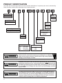
PRODUCT IDENTIFICATION
The model and manufacturing number are used for positive identification of component parts used in manufacturing.
Please use these numbers when requesting service or parts information.
A
M
V
8
090 5 C
X
A
A
Product Type
Minor
Revision
A: Amana
A: Initial
Release
Supply Type
M: Upflow/Horizontal
Major
Revision
A: Initial
Release
Furnace Type
V: 2 Stage/Variable Speed
Additional Features
N: Natural Gas
X: Low NOx
AFUE
8: 80%
Cabinet Width
B: 17 1/2"
C: 21"
Nominal Input
070:
090:
115:
2
70,000 Btuh
90,000 Btuh
115,000 Btuh
Airflow Capability
4: 1600
5: 2000
WARNING
HIGH VOLTAGE!
Disconnect ALL power before servicing or installing this unit. Multiple
power sources may be present. Failure to do so may cause property
damage, personal injury or death.
WARNING
Installation and repair of this unit should be performed ONLY by individuals
meeting the requirements of an "entry level technician" as specified by the Air
Conditioning and Refrigeration Institute (ARI). Attempting to install or repair
this unit without such background may result in product damage, personal
injury or death.
WARNING
Goodman will not be responsibile for any injury or property damage arising
from improper service or service procedures. If you install or perform
service on this unit, you assume responsibility for any personal injury or
property damage which may result. Many jurisdictions require a license to
install or service heating and air conditioning equipment.
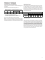
PRODUCT IDENTIFICATION
The model and manufacturing number are used for positive identification of component parts used in manufacturing.
Please use these numbers when requesting service or parts information.
AMV80704BX**
AMV80905CX**
AMV81155CX**
WARNING
The United States Environmental Protection Agency (“EPA”) has issued
various regulations regarding the introduction and disposal of refrigerants
introduced into this unit. Failure to follow these regulations may harm the
environment and can lead to the imposition of substantial fines. These
regulations may vary by jurisdiction. Should questions arise, contact your
local EPA office.
WARNING
To prevent the risk of property damage, personal injury, or death, do not
store combustible materials or use gasoline or other flammable liquids or
vapors in the vicinity of this appliance.
WARNING
Do not connect or use any device that is not design certified by Goodman
for use with this unit. Serious property damage, personal injury, reduced
unit performance and/or hazardous conditions may result from the use of
such non-approved devices.
3
PRODUCT DESIGN
General Operation
Notes:
AMV8 furnaces are equipped with an electronic ignition device used to light the burners and an induced draft blower to
exhaust combustion products.
1. Category I Venting is venting at a non-positive pressure.
A furnace vented as Category I is considered a fan-assisted appliance and the vent system does not have to
be “gas tight.”
An interlock switch prevents furnace operation if the blower
door is not in place. Keep the blower access door in place
except for inspection and maintenance. (See illustration on
page 6.)
This furnace is also equipped with a self-diagnosing electronic control module. In the event a furnace component is
not operating properly, the control module LED will flash on
and off in a factory-programmed sequence, depending on
the problem encountered. This light can be viewed through
the observation window in the blower access door. Refer to
the Troubleshooting Chart for further explanation of the LED
codes and Abnormal Operation - Integrated Ignition Control
section in the Service Instructions for an explanation of the
possible problem.
The rated heating capacity of the furnace should be greater
than or equal to the total heat loss of the area to be heated.
The total heat loss should be calculated by an approved
method or in accordance with “ASHRAE Guide” or “Manual
J-Load Calculations” published by the Air Conditioning Contractors of America.
NOTE: Gas furnaces with induced draft blowers draw
products of combustion through a heat exchanger allowing,
in some instances, common venting with natural draft
appliances (i.e. water heaters).
All installations must be vented in accordance with National
Fuel Gas Code NFPA 54/ANSI Z223.1 - latest edition. In
Canada, the furnaces must be vented in accordance with
the National Standard of Canada, CAN/CSA B149.1 and
CAN/CSA B149.2 - latest editions and amendments.
NOTE: The vertical height of the Category I venting system
must be at least as great as the horizontal length of the
venting system.
WARNING
TO PREVENT POSSIBLE PERSONAL INJURY OR DEATH DUE TO ASPHYXIATION,
COMMON VENTING WITH OTHER MANUFACTURER'S INDUCED DRAFT APPLIANCS
IS NOT ALLOWED.
*Obtain from: American National Standards Institute 1430
Broadway New York, NY 10018
Location Considerations
•
The furnace should be as centralized as is practical
with respect to the air distribution system.
•
Do not install the furnace directly on carpeting, tile, or
combustible material other than wood flooring.
•
When suspending the furnace from rafters or joists,
use 3/8" threaded rod and 2” x 2” x 3/8” angle as
shown in the Installation and Service Instructions. The
length of the rod will depend on the application and
clearance necessary.
•
When installed in a residential garage, the furnace
must be positioned so the burners and ignition source
are located not less than 18 inches (457 mm) above
the floor and protected from physical damage by vehicles.
WARNING
TO PREVENT POSSIBLE PERSONAL INJURY OR DEATH DUE TO ASPHYXIATION,
THIS FURNACE MUST BE CATEGORY I VENTED. DO NOT VENT USING
CATEGORY III VENTING.
4
2. Line voltage wiring can enter through the right or left side
of the furnace. Low voltage wiring can enter through the
right or left side of furnace.
3. Conversion kits for high altitude natural or propane gas
operation are available. See High Altitude Derate chart
for details.
4. Installer must supply the following gas line fittings, depending on which entrance is used:
Left -- Two 90º Elbows, one close nipple, straight pipe.
Right -- Straight pipe to reach gas valve.
PRODUCT DESIGN
Accessibility Clearances (Minimum)
High Altitude Derate
Unobstructed front clearanace of 24" for servicing is recommended.
When this furnace is installed at high altitude, the appropriate High Altitude orifice kit must be installed. This is required due to the natural reduction in the density of both the
gas fuel and combustion air as altitude increases. The kit
will provide the proper design certified input rate within the
specified altitude range.
Top clearance for horizontal confirguration - 1"
MINIMUM CLEARANCE TO COMBUSTIBLE MATERIALS - INCHES
Sides
Rear
Front*
1
0
3
Vent
SW
B
6
1
Top
INPUT PER BURNER - 22,500 BTUH NATURAL GAS / 20,000 BTUH L.P.
1
Approved for line contact in the horizontal position.
* 24" clearnace for serviceability recommended.
** Single Wall Vent (SW) to be used only as a conncetor.
Refer to the venting tables outlined in the Installation Manual for
24" at front is required for servicing or cleaning.
Note: In all cases accessibility clearance shall take precedence over clearances from the enclosure where accessibility clearances are greater. All dimensions are given in inches.
ELEVATION ABOVE SEA-LEVEL (FEET)
2000
3000
4000
US BURNER
ORIFICE
44/55
44/55
45/56
CANADA BURNER
ORIFICE
44/55
4500
5000
6000
7000
8000
45/56
46/57
47/58
47/58
47/57
HA-02 HIGH ALTITUDE CONVERSION KIT REQUIRED
Tabled data is based upon the furnace input being reduced for altitudes above sea level. U.S. 4% per 1,000 feet.
Canada 10% derate for 2,000-4,000 feet.
High altitude kits are purchased according to the installation altitude and usage of either natural or propane gas. Refer
to the chart above for a tabular listing of appropriate altitude
ranges and corresponding manufacturer’s high altitude Natural Gas and Propane Gas kits. For a tabular listing of appropriate altitude ranges and corresponding manufacturer's High
Altitude Pressure Switch kits, refer to either the Pressure
Switch Trip Points & Usage Chart in this manual or the Accessory Charts in Service Instructions.
5
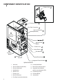
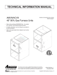
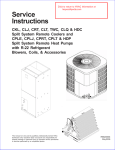
COMPONENT IDENTIFICATION
Primary Limit
Pressure Switch
Flue Pipe Connection
Gas Line Entrance
(Alternate)
Gas Line
Entrance
Induced Draft
Blower
Rollout Limit
Inshot Burner
Gas Manifold
Circulator
Blower
Junction
Box
Transformer
Integrated Control Module
Upflow/Horizontal
1
Gas Valve
10 Induced Draft Blower
2
Gas Line Entrance (Alternate)
11 Blower Door Interlock Switch
3
Pressure Switch(es)
12 Integrated Control Module
4
Gas Manifold
5
Rollout Limit
13 Transformer (40 VA)
7 Primary Limit
14 Circulator Blower
8 Gas Line Entrance
15 Junction Box
9 Flue Pipe Connection (Alternate)
6
(with fuse and diagnostic LED)
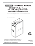
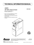
PRODUCT DIMENSIONS
AMV8*****XA
Alt. Vent Location
Alt. Vent Location
Alt. Gas Inlet
Alt. High Voltage
CABINET SIZE
A
B
AMV80704BX**
17½
16
AMV80905CX**
21
21
AMV81155CX**
21
21
All dimensions are in inches
7
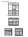
PRODUCT DESIGN
PRESSURE SWITCH TRIP POINTS
AND USAGE CHART
0 to 8,000 ft.
MODEL
Negative
Pressure ID
Blower With
ID BLOWER
Flue not Firing PRESSURE
typical Sea
SWITCH
(1)
PART #
Level Data
LOW
FIRE
HIGH
FIRE
AMV80704BX**
-0.30
-0.45
B1370208
AMV80905CX**
-0.30
-0.50
B1370209
AMV81155CX**
-0.30
-0.55
B1370210
Note: All negative pressure readings are in inches of water column (" w.c.).
(1) Data given is least negative pressure required for pressure switch to close.
T.O.D. PRIMARY LIMIT
Part Number
B1370198
B1370207
Open Setting (°F)
150
130
AMV80704BX**
1
AMV80905CX**
1
AMV81155CX*
ROLLOUT LIMIT SWITCH
8
1
AUXILIARY LIMIT SWITCHES
Part Number
B1370145
Part Number
20269903
Open Setting (°F)
300
Open Setting (°F)
150
AMV80704BX**
1
AMV80704BX**
2
AMV80905CX**
1
AMV80905CX**
2
AMV81155CX**
1
AMV81155CX**
2
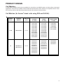
PRODUCT DESIGN
Coil Matches:
A large array of Amana® brand coils are available for use with the new AMV8 furnaces, in either upflow or horizontal
applications. These coils are available in both cased and uncased models, with or without a TXV expansion device. These
80% furnaces match up with the existing Amana® brand coils as shown in the chart below.
Coil Matches (for Amana® brand units using R22 and R-410A):
CABINET
WIDTH
17 1/2
21
FURNACE
MODELS
AMV80704BX**
AMV80905CX**
AMV81155CX**
AIRFLOW
(tons)
CAUF
UNCASED
"A" COILS
CAPF
CASED
"A" COILS
CHPF
HORIZ. CASED
"A" COIL
CAPF018B2*
CAPF025B2*
CAPF030B2*
CAPF039B2*
CAPF036B2*
CAPF037B2*
CAPF042B2*
CAPF1824B6*
CAPF3030B6*
CAPF3131B6*
CAPF3636B6*
CHPF036B2*
CHPF042B2*
CHPF048B2*
CHPF2430B6*
CHPF3636B6*
1 1/2 - 3
CAUF018B2*
CAUF025B2*
CAUF030B2*
CAUF036B2*
CAUF037B2*
CAUF042B2*
CAUF048B2*
CAUF1824B6*
CAUF3030B6*
CAUF3131B6*
CAUF3636B6*
CAUF042C2*
CAUF048C2*
CAUF049C2*
CAUF060C2*
CAUF061C2*
CAUF1324C6*
CAUF3030C6*
CAUF3636C6*
CAUF3642C6*
CAUF4860C6*
CAPF036C2*
CAPF042C2*
CAPF1824C6*
CAPF3030C6*
CAPF3131C6*
CAPF3636C6*
CAPF3642C6*
CHPF048D2*
CHPF060D2*
CHPF3642C*
2 1/2 - 4
9
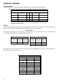
PRODUCT DESIGN
Thermostats:
The following Amana® brand Thermostats are suggested for use with the AMV8 Furnace Models:
Two-Stage Thermostat Description
Thermostat
Programmable
Cool
Heat
Hard Wired
Battery Powered
1213411
No
2
2
Yes
Yes
1213407
Yes
1
2
Yes
Yes
1213406*
Yes
2
3
Yes
No
* For use in dual-fuel applications with a heat pump in a fossil fuel application. It is not for use with
the AMV8 as a sole heating source.
Filters:
Filters are required with this furnace and must be provided by the installer. The filters used must comply with UL900 or
CAN/ULCS111 standards. Installing this furnace without filters will void the unit warranty.
Upflow Filters
This furnace has provisions for the installation of return air filters at the side and/or bottom return. The furnace will
accommodate the following filter sizes depending on cabinet size:
Cabinet
Width
(in.)
All
Side Return(s)
Approx.
Nominal
Filter Size Flow Area
(in.)
(in2)
16 x 25 x 1
400
Cabinet
Width
(in.)
17-1/2
21
Bottom Return
Approx.
Nominal
Filter Size Flow Area
(in.)
(in2)
14 x 25 x 1
288
16 x 25 x 1
480
Refer to Minimum Filter Area tables to determine filter area requirement. NOTE: Filters can also be installed elsewhere in
the duct system such as a central return.
MINIMUM FILTER SIZES
FURNACE INPUT
FILTER SIZE
TYPE
45M
160 in2
permanent
70M
241 in2
permanent
90M
2
permanent
2
permanent
2
permanent
2
disposable
2
disposable
2
disposable
2
disposable
2
disposable
115M
140M
45M
70M
90M
115M
140M
320 in
400 in
370 in
320 in
483 in
640 in
800 in
738 in
PERMANENT NOMINAL 600 F.M. FACE VELOCITY
DISPOSABLE NOMINAL 300 F.M. FACE VELOCITY
10
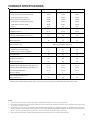
FURNACE SPECIFICATIONS
MODEL
AMV80704BX**
AMV80905CX**
AMV81155CX**
70,000
90,000
115,000
Output (US) High Fire (Natural Gas), BTUH
57,000
74,000
93,000
Output (US) High Fire (LP), BTUH
49,000
64,000
82,000
Btuh Input (US) Low Fire (Natural Gas)
52,500
67,500
86,000
Output (US) Low Fire (Natural Gas), BTUH
42,000
54,000
69,000
Output (US) Low Fire (LP), BTUH
42,000
54,000
69,000
80%
80%
80%
Rated External Static (" w.c.)
.20 - .50
.20 - .50
.20 - .50
Temperature Rise (°F)
20 - 50
25 - 55
25 - 55
High Stage Pressure Switch Trip Point (" w.c.)
-0.45
-0.60
-0.55
Low Stage Pressure Switch Trip Point (" w.c.)
-0.30
-0.30
-0.30
Blower Wheel (D" x W")
10 x 8
10 x 10
10 x 10
3/4
3/4
3/4
Btuh Input (US) High Fire (Natural Gas)
A.F.U.E.
Blower Horsepower
Blower Speeds
VARIABLE
Refer to airflow charts on page 12-14.
Max CFM @ 0.5 E.S.P.
Power Supply
Minimum Circuit Ampacity (MCA)
(1)
(2)
115 VAC / 60 HZ / 1 PH
11.7
11.7
11.7
15
15
15
40
40
40
Primary Limit Setting (°F)
150
150
130
Auxiliary Limit Setting (°F)
150
150
150
Rollout Limit Setting (°F)
300
300
300
Gas Supply Pressure (Natural/Propane) (" w.c.)
7 / 11
7 / 11
7 / 11
Manifold Pressure (Natural/Propane) High Stage (" w.c.)
3.5 / 10
3.5 / 10
3.5 / 10
Manifold Pressure (Natural/Propane) Low Stage ("w.c.)
1.6 / 6.3
1.6 / 6.3
1.6 / 6.3
Orifice Size (Natural/Propane)
43 / 55
43 / 55
43 / 55
3
4
5
4
4
4
152
178
194
Number of Burners
Vent Connector Diameter (inches)
Shipping Weight (lbs.)
(2)
115 VAC / 60 HZ / 1 PH
Transformer (VA)
Maximum Overcurrent Device (AMPS)
(1)
115 VAC / 60 HZ / 1 PH
(4)
Minimum Circuit Ampacity calculated as: (1.25 x Circulator Blower Amps) + I.D. Blower Amps.
Maximum Overcurrent Protection Device: May use Time Delay Fuse or HACR type Circuit Breaker of the same size as noted.
NOTES:
1.
These furnaces are manufactured for natural gas operation. Optional kits are available for conversion to propane operation.
2.
For elevations above 2000 feet the rating should be reduced by 4% for each 1000 feet above sea level. The furnace must not be derated, orifice changes should
only be made if necessary for altitude.
3.
The total heat loss from the structure as expressed in TOTAL BTU/HR must be calculated by the manufacturers method or in accordance with the "A.S.H.R.A.E.
GUIDE" or "MANUAL J-LOAD CALCULATIONS" published by the AIR CONDITIONING CONTRACTORS OF AMERICA. The total heat loss calculated should be
equal to or less than the heating capacity. Output based on D.O.E. test procedures, steady state efficiency times output.
4.
Wire size should be determined in accordance with National Electrical Codes. Extensive wire runs will require larger wire sizes.
11
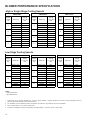
BLOWER PERFORMANCE SPECIFICATIONS
High or Single-Stage Cooling Speeds
AMV80704BX**
Cooling
Speed
Tap
A
B
C
D
AMV80905CX**
Adjust Tap
CFM @
.1" to .8" W.C.
ESP
Minus (-) Tap
540
Cooling
Speed
Tap
A
AMV81155CX**
Adjust Tap
CFM @
.1" to .8" W.C.
ESP
Minus (-) Tap
720
Cooling
Speed
Tap
A
Adjust Tap
CFM @
.1" to .8" W.C.
ESP
Minus (-) Tap
720
Nominal
800
Nominal
600
Nominal
800
Plus (+) Tap
660
Plus (+) Tap
880
Plus (+) Tap
880
Minus (-) Tap
720
Minus (-) Tap
990
Minus (-) Tap
990
Nominal
800
Nominal
1,100
Nominal
1,100
1,210
B
B
Plus (+) Tap
880
Plus (+) Tap
1,210
Plus (+) Tap
Minus (-) Tap
900
Minus (-) Tap
1,260
Minus (-) Tap
1,260
Nominal
1,100
Nominal
1,400
Nominal
1,400
Plus (+) Tap
1,210
Plus (+) Tap
1,540
Plus (+) Tap
1,540
Minus (-) Tap
1,260
Nominal
1,400
Plus (+) Tap
1,540
C
D
Minus (-) Tap
1,620
Nominal
1,800
Plus (+) Tap
1,980
C
D
Minus (-) Tap
1,620
Nominal
1,800
Plus (+) Tap
1,980
Low-Stage Cooling Speeds
AMV80704BX**
Cooling
Speed
Tap
A
B
C
D
AMV80905CX**
Adjust Tap
CFM @
.1" to .8" W.C.
ESP
Minus (-) Tap
361
Nominal
390
Cooling
Speed
Tap
**
A
Adjust Tap
AMV81155CX**
CFM @
.1" to .8" W.C.
ESP
Minus (-) Tap
563**
Nominal
563**
Cooling
Speed
Tap
A
Adjust Tap
CFM @
.1" to .8" W.C.
ESP
Minus (-) Tap
563**
Nominal
563**
572
Plus (+) Tap
429
Plus (+) Tap
572
Plus (+) Tap
Minus (-) Tap
468
Minus (-) Tap
644
Minus (-) Tap
644
Nominal
420
Nominal
715
Nominal
715
787
B
B
Plus (+) Tap
572
Plus (+) Tap
787
Plus (+) Tap
Minus (-) Tap
644
Minus (-) Tap
819
Minus (-) Tap
819
Nominal
715
Nominal
910
Nominal
910
Plus (+) Tap
787
Plus (+) Tap
1,001
Plus (+) Tap
1,001
Minus (-) Tap
819
Nominal
910
Plus (+) Tap
1,001
C
D
Minus (-) Tap
1,053
Nominal
1,170
Plus (+) Tap
1,287
C
D
Minus (-) Tap
1,053
Nominal
1,170
Plus (+) Tap
1,287
NOTES:
* Motor CFM maximum
** Motor CFM minimum
1.
These charts are for furnaces installed at 0' - 4,500'. At higher altitudes, a properly derated unit will have the same temperature rise at a
particular CFM, while the ESP at that CFM will be lower.
2.
The installation must be adjusted to obtain a temperature rise within the range listed on the furnace nameplate.
3.
Do not operate above .5" w.c. ESP in heating mode.
4.
Propane gas installations will have a High Stage rise approximately 4° lower than shown in above table.
12
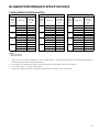
BLOWER PERFORMANCE SPECIFICATIONS
Cooling-Based Continuous Fan
AMV80704BX**
Cooling
Speed
Tap
A
B
C
D
Adjust Tap
AMV80905CX**
CFM @
.1" to .8" W.C.
ESP
Minus (-) Tap
361**
Nominal
361**
Cooling
Speed
Tap
A
Adjust Tap
AMV81155CX**
CFM @
.1" to .8" W.C.
ESP
Minus (-) Tap
563**
Nominal
563**
Cooling
Speed
Tap
A
Adjust Tap
CFM @
.1" to .8" W.C.
ESP
Minus (-) Tap
563**
Nominal
563**
Plus (+) Tap
370
Plus (+) Tap
563**
Plus (+) Tap
563**
Minus (-) Tap
403
Minus (-) Tap
563**
Minus (-) Tap
563**
Nominal
448
Nominal
616
Nominal
616
678
B
B
Plus (+) Tap
493
Plus (+) Tap
678
Plus (+) Tap
Minus (-) Tap
554
Minus (-) Tap
706
Minus (-) Tap
706
Nominal
616
Nominal
784
Nominal
784
862
C
C
Plus (+) Tap
678
Plus (+) Tap
862
Plus (+) Tap
Minus (-) Tap
706
Minus (-) Tap
9*07
Minus (-) Tap
907
Nominal
784
Nominal
1,008
Nominal
1,008
Plus (+) Tap
862
Plus (+) Tap
1,109
Plus (+) Tap
1,109
D
D
NOTES:
* Motor CFM maximum
** Motor CFM minimum
1.
These charts are for furnaces installed at 0' - 4,500'. At higher altitudes, a properly derated unit will have the same temperature rise at a
particular CFM, while the ESP at that CFM will be lower.
2.
The installation must be adjusted to obtain a temperature rise within the range listed on the furnace nameplate.
3.
Do not operate above .5" w.c. ESP in heating mode.
4.
Propane gas installations will have a High Stage rise approximately 4° lower than shown in above table.
13
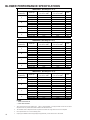
BLOWER PERFORMANCE SPECIFICATIONS
AMV80704BX** (Rise Range 20 - 50 °F)
Heating
Speed Tap
A
B
C
D
Adjust Tap
Low Stage CFM @
.1" to .5" w.c. ESP
High Stage CFM @
.1" to .5" w.c. ESP
Rise
Minus (-) Tap
Nominal
Plus (+) Tap
Minus (-) Tap
Nominal
Plus (+) Tap
Minus (-) Tap
Nominal
Plus (+) Tap
Minus (-) Tap
Nominal
Plus (+) Tap
810
900
990
900
1,000
1,100
990
1,100
1,210
1,080
1,200
1,320
1,077
1,197
1,317
1,197
1,330
1,463
1,317
1,463
1,609
1,436
1,596
1650*
48
43
39
43
39
35
39
35
32
36
32
29
AMV80905CX** (Rise Range 25 - 55 °F)
Heating
Speed Tap
A
B
C
D
Adjust Tap
Low Stage CFM @
.1" to .5" w.c. ESP
High Stage CFM @
.1" to .5" w.c. ESP
Rise
Minus (-) Tap
Nominal
Plus (+) Tap
Minus (-) Tap
Nominal
Plus (+) Tap
Minus (-) Tap
Nominal
Plus (+) Tap
Minus (-) Tap
Nominal
Plus (+) Tap
945
1,050
1,155
1,035
1,150
1,265
1,125
1,250
1,375
1,215
1,350
1,485
1,257
1,397
1,536
1,377
1,530
1,682
1,496
1,663
1,829
1,616
1,796
1,975
53
48
43
48
43
40
44
40
36
41
37
34
AMV81155CX** (Rise Range 25 - 55 °F)
Heating
Speed Tap
A
B
C
D
Adjust Tap
Low Stage CFM @
.1" to .5" w.c. ESP
High Stage CFM @
.1" to .5" w.c. ESP
Rise
Minus (-) Tap
Nominal
Plus (+) Tap
Minus (-) Tap
Nominal
Plus (+) Tap
Minus (-) Tap
Nominal
Plus (+) Tap
Minus (-) Tap
Nominal
Plus (+) Tap
1,170
1,300
1,430
1,215
1,350
1,485
1,260
1,400
1,540
1,373
1,525
1,678
1,556
1,729
1,902
1,616
1,796
1,975
1,676
1,862
2000*
1,825
2000*
2,000*
55
49
45
53
47
43
51
46
41
47
42
38
NOTES:
* Motor CFM maximum
** Motor CFM minimum
14
1.
These charts arefor furnaces installed at 0' - 4,500'. At higher altitudes, a prooperly derated unti will have the same
temperature rise at a particular CFM, while the ESP at the CFM will be lower.
2.
The installation must be adjusted to obtain a emperature rise within the range listed on the furnace nameplate.
3.
Do not operate above .5" w.c. EXP in heating mode.
4.
Propane gas installations iwll have High Stage rise approximately 4° lower than shown in above table.
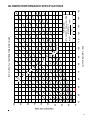
TEMPERATURE RISE
10
20
30
40
30
50
60
70
80
90
100
40
50
60
700
600 CFM
90
100
2000
2200
2400 CFM
1800
1600
1400
OUTPUT BTU/HR x 1000
80
1200
1100
1000
900
70
800
FORMULAS
110
120
130
140
BTU OUTPUT = CFM x 1.08 x RISE
BTU OUTPUT
RISE =
÷ CFM
1.08
BTU OUTPUT vs TEMPERATURE RISE CHART
150
BLOWER PERFORMANCE SPECIFICATIONS
15
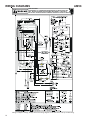
WIRING DIAGRAMS
AMV8
HIGH VOLTAGE!
DISCONNECT ALL POWER BEFORE SERVICING OR INSTALLING THIS
UNIT. MULTIPLE POWER SOURCES MAY BE PRESENT. FAILURE TO
DO SO MAY CAUSE PROPERTY DAMAGE, PERSONAL INJURY OR DEATH.
Wiring is subject to change, always refer to the wiring diagram on the unit for the most up-to-date wiring.
16
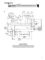
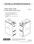
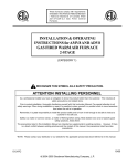
SCHEMATICS
HIGH VOLTAGE!
DISCONNECT ALL POWER BEFORE SERVICING OR INSTALLING THIS
UNIT. MULTIPLE POWER SOURCES MAY BE PRESENT. FAILURE TO
DO SO MAY CAUSE PROPERTY DAMAGE, PERSONAL INJURY OR DEATH.
ELECTRONIC
AIR CLEANER
INDUCER
EAC EAC
NEU
IND IND IND
HI
LO NEU HUM
HUMIDIFIER
13
ENABLE
LOW
HEAT
HI
HEAT
16 PIN VARIABLE SPD
MOTOR CONNECTOR
2
C.
CIR
U
NE
CIRC.
HOT
15
HUMN
TRANSISITOR
LOGIC
MVH
R
TRANSISITOR
LOGIC
W9
G
BK
W10
TH
HEAT CIRC.
REQUEST FROM
MICRO
XFMR
.24 V.A.C
XFMRN
.0005
TR
B/C
G
LINE HOT
K8 b
MVH
120 VAC
LINE NEU
Q22
K6
1M
FP
IGNN
FLAME
SENSOR
PROBE
IGNITOR
IGN
GND
MV MV
L
COM
P
C M
H1
2 STAGE
GAS
VAL VE
PS2
PS1 HLO
HIGH
LIMIT
HLI
ROLLOUT
SWITCH
Y
G
W2
W1
YLO
O
R
Y
G
W2
W1
YLO
THERMOSTAT
MVH
AUX
LIMIT
1ST STAGE
PRESSURE
SWITCH
2ND STAGE
PRESSURE
SWITCH
TYPICAL SCHEMATIC
AMV8 MODEL FURNACES
WHITE-RODGERS 50V61-289 INTEGRATED IGNITION CONTROL
This schematic is for reference only. Not all wiring is as shown above,
refer to the appropriate wiring diagram for the unit being serviced.
17