1
User Guide
Streaming AV Products
JMP 9600
Two-Channel JPEG 2000 HD Video Player
68-1943-01 Rev. A
01 12
Safety Instructions • English
Warning
This symbol is intended to alert the user of important operating and maintenance (servicing) instructions in the literature provided with the equipment.
Power sources • This equipment should be operated only from the power source indicated on the product. This
equipment is intended to be used with a main power system with a grounded (neutral) conductor. The third
(grounding) pin is a safety feature, do not attempt to bypass or disable it.
This symbol is intended to alert the user of the presence of uninsulated
dangerous voltage within the product’s enclosure that may present a risk of
electric shock.
Power disconnection • To remove power from the equipment safely, remove all power cords from the rear of
the equipment, or the desktop power module (if detachable), or from the power source receptacle (wall plug).
Caution
Read Instructions • Read and understand all safety and operating instructions before using the equipment.
Retain Instructions • The safety instructions should be kept for future reference.
Follow Warnings • Follow all warnings and instructions marked on the equipment or in the user information.
Avoid Attachments • Do not use tools or attachments that are not recommended by the equipment
manufacturer because they may be hazardous.
Consignes de Sécurité • Français
Ce symbole sert à avertir l’utilisateur que la documentation fournie avec le
matériel contient des instructions importantes concernant l’exploitation et la
maintenance (réparation).
Ce symbole sert à avertir l’utilisateur de la présence dans le boîtier
de l’appareil de tensions dangereuses non isolées posant des risques
d’électrocution.
Attention
Lire les instructions• Prendre connaissance de toutes les consignes de sécurité et d’exploitation avant
d’utiliser le matériel.
Conserver les instructions• Ranger les consignes de sécurité afin de pouvoir les consulter à l’avenir.
Respecter les avertissements • Observer tous les avertissements et consignes marqués sur le matériel ou
présentés dans la documentation utilisateur.
Eviter les pièces de fixation • Ne pas utiliser de pièces de fixation ni d’outils non recommandés par le
fabricant du matériel car cela risquerait de poser certains dangers.
Sicherheitsanleitungen • Deutsch
Power cord protection • Power cords should be routed so that they are not likely to be stepped on or pinched
by items placed upon or against them.
Servicing • Refer all servicing to qualified service personnel. There are no user-serviceable parts inside. To prevent
the risk of shock, do not attempt to service this equipment yourself because opening or removing covers may
expose you to dangerous voltage or other hazards.
Slots and openings • If the equipment has slots or holes in the enclosure, these are provided to prevent
overheating of sensitive components inside. These openings must never be blocked by other objects.
Lithium battery • There is a danger of explosion if battery is incorrectly replaced. Replace it only with the
same or equivalent type recommended by the manufacturer. Dispose of used batteries according to the
manufacturer’s instructions.
Avertissement
Alimentations • Ne faire fonctionner ce matériel qu’avec la source d’alimentation indiquée sur l’appareil. Ce
matériel doit être utilisé avec une alimentation principale comportant un fil de terre (neutre). Le troisième
contact (de mise à la terre) constitue un dispositif de sécurité : n’essayez pas de la contourner ni de la
désactiver.
Déconnexion de l’alimentation• Pour mettre le matériel hors tension sans danger, déconnectez tous les
cordons d’alimentation de l’arrière de l’appareil ou du module d’alimentation de bureau (s’il est amovible) ou
encore de la prise secteur.
Protection du cordon d’alimentation • Acheminer les cordons d’alimentation de manière à ce que personne
ne risque de marcher dessus et à ce qu’ils ne soient pas écrasés ou pincés par des objets.
Réparation-maintenance • Faire exécuter toutes les interventions de réparation-maintenance par un
technicien qualifié. Aucun des éléments internes ne peut être réparé par l’utilisateur. Afin d’éviter tout danger
d’électrocution, l’utilisateur ne doit pas essayer de procéder lui-même à ces opérations car l’ouverture ou le
retrait des couvercles risquent de l’exposer à de hautes tensions et autres dangers.
Fentes et orifices • Si le boîtier de l’appareil comporte des fentes ou des orifices, ceux-ci servent à empêcher les
composants internes sensibles de surchauffer. Ces ouvertures ne doivent jamais être bloquées par des objets.
Lithium Batterie • Il a danger d’explosion s’ll y a remplacment incorrect de la batterie. Remplacer uniquement
avec une batterie du meme type ou d’un ype equivalent recommande par le constructeur. Mettre au reut les
batteries usagees conformement aux instructions du fabricant.
Vorsicht
Dieses Symbol soll dem Benutzer in der im Lieferumfang enthaltenen
Dokumentation besonders wichtige Hinweise zur Bedienung und Wartung
(Instandhaltung) geben.
Stromquellen • Dieses Gerät sollte nur über die auf dem Produkt angegebene Stromquelle betrieben werden.
Dieses Gerät wurde für eine Verwendung mit einer Hauptstromleitung mit einem geerdeten (neutralen) Leiter
konzipiert. Der dritte Kontakt ist für einen Erdanschluß, und stellt eine Sicherheitsfunktion dar. Diese sollte nicht
umgangen oder außer Betrieb gesetzt werden.
Dieses Symbol soll den Benutzer darauf aufmerksam machen, daß im Inneren
des Gehäuses dieses Produktes gefährliche Spannungen, die nicht isoliert sind
und die einen elektrischen Schock verursachen können, herrschen.
Stromunterbrechung • Um das Gerät auf sichere Weise vom Netz zu trennen, sollten Sie alle Netzkabel aus der
Rückseite des Gerätes, aus der externen Stomversorgung (falls dies möglich ist) oder aus der Wandsteckdose
ziehen.
Achtung
Lesen der Anleitungen • Bevor Sie das Gerät zum ersten Mal verwenden, sollten Sie alle Sicherheits-und
Bedienungsanleitungen genau durchlesen und verstehen.
Aufbewahren der Anleitungen • Die Hinweise zur elektrischen Sicherheit des Produktes sollten Sie
aufbewahren, damit Sie im Bedarfsfall darauf zurückgreifen können.
Befolgen der Warnhinweise • Befolgen Sie alle Warnhinweise und Anleitungen auf dem Gerät oder in der
Benutzerdokumentation.
Keine Zusatzgeräte • Verwenden Sie keine Werkzeuge oder Zusatzgeräte, die nicht ausdrücklich vom
Hersteller empfohlen wurden, da diese eine Gefahrenquelle darstellen können.
Instrucciones de seguridad • Español
Este símbolo se utiliza para advertir al usuario sobre instrucciones importantes de operación y mantenimiento (o cambio de partes) que se desean
destacar en el contenido de la documentación suministrada con los equipos.
Este símbolo se utiliza para advertir al usuario sobre la presencia de elementos con voltaje peligroso sin protección aislante, que puedan encontrarse
dentro de la caja o alojamiento del producto, y que puedan representar
riesgo de electrocución.
Precaucion
Leer las instrucciones • Leer y analizar todas las instrucciones de operación y seguridad, antes de usar el
equipo.
Conservar las instrucciones • Conservar las instrucciones de seguridad para futura consulta.
Obedecer las advertencias • Todas las advertencias e instrucciones marcadas en el equipo o en la
documentación del usuario, deben ser obedecidas.
安全须知 • 中文
这个符号提示用户该设备用户手册中有重要的操作和维护说明。
这个符号警告用户该设备机壳内有暴露的危险电压,有触电危险。
注意
阅读说明书 • 用户使用该设备前必须阅读并理解所有安全和使用说明。
保存说明书 • 用户应保存安全说明书以备将来使用。
遵守警告 • 用户应遵守产品和用户指南上的所有安全和操作说明。
避免追加 • 不要使用该产品厂商没有推荐的工具或追加设备,以避免危险。
Schutz des Netzkabels • Netzkabel sollten stets so verlegt werden, daß sie nicht im Weg liegen und niemand
darauf treten kann oder Objekte darauf- oder unmittelbar dagegengestellt werden können.
Wartung • Alle Wartungsmaßnahmen sollten nur von qualifiziertem Servicepersonal durchgeführt werden.
Die internen Komponenten des Gerätes sind wartungsfrei. Zur Vermeidung eines elektrischen Schocks
versuchen Sie in keinem Fall, dieses Gerät selbst öffnen, da beim Entfernen der Abdeckungen die Gefahr eines
elektrischen Schlags und/oder andere Gefahren bestehen.
Schlitze und Öffnungen • Wenn das Gerät Schlitze oder Löcher im Gehäuse aufweist, dienen diese zur
Vermeidung einer Überhitzung der empfindlichen Teile im Inneren. Diese Öffnungen dürfen niemals von
anderen Objekten blockiert werden.
Litium-Batterie • Explosionsgefahr, falls die Batterie nicht richtig ersetzt wird. Ersetzen Sie verbrauchte Batterien
nur durch den gleichen oder einen vergleichbaren Batterietyp, der auch vom Hersteller empfohlen wird.
Entsorgen Sie verbrauchte Batterien bitte gemäß den Herstelleranweisungen.
Evitar el uso de accesorios • No usar herramientas o accesorios que no sean especificamente recomendados
por el fabricante, ya que podrian implicar riesgos.
Advertencia
Alimentación eléctrica • Este equipo debe conectarse únicamente a la fuente/tipo de alimentación eléctrica
indicada en el mismo. La alimentación eléctrica de este equipo debe provenir de un sistema de distribución
general con conductor neutro a tierra. La tercera pata (puesta a tierra) es una medida de seguridad, no
puentearia ni eliminaria.
Desconexión de alimentación eléctrica • Para desconectar con seguridad la acometida de alimentación
eléctrica al equipo, desenchufar todos los cables de alimentación en el panel trasero del equipo, o desenchufar
el módulo de alimentación (si fuera independiente), o desenchufar el cable del receptáculo de la pared.
Protección del cables de alimentación • Los cables de alimentación eléctrica se deben instalar en lugares
donde no sean pisados ni apretados por objetos que se puedan apoyar sobre ellos.
Reparaciones/mantenimiento • Solicitar siempre los servicios técnicos de personal calificado. En el interior no
hay partes a las que el usuario deba acceder. Para evitar riesgo de electrocución, no intentar personalmente la
reparación/mantenimiento de este equipo, ya que al abrir o extraer las tapas puede quedar expuesto a voltajes
peligrosos u otros riesgos.
Ranuras y aberturas • Si el equipo posee ranuras o orificios en su caja/alojamiento, es para evitar el
sobrecalientamiento de componentes internos sensibles. Estas aberturas nunca se deben obstruir con otros
objetos.
Batería de litio • Existe riesgo de explosión si esta batería se coloca en la posición incorrecta. Cambiar esta
batería únicamente con el mismo tipo (o su equivalente) recomendado por el fabricante. Desachar las baterías
usadas siguiendo las instrucciones del fabricante.
警告
电源 • 该设备只能使用产品上标明的电源。 设备必须使用有地线的供电系统供电。 第三条线
(地线)是安全设施,不能不用或跳过 。
拔掉电源 • 为安全地从设备拔掉电源,请拔掉所有设备后或桌面电源的电源线,或任何接到市
电系统的电源线。
电源线保护 • 妥善布线, 避免被踩踏,或重物挤压。
维护 • 所有维修必须由认证的维修人员进行。 设备内部没有用户可以更换的零件。为避免出现
触电危险不要自己试图打开设备盖子维修该设备。
通风孔 • 有些设备机壳上有通风槽或孔,它们是用来防止机内敏感元件过热。 不要用任何东
西挡住通风孔。
锂电池 • 不正确的更换电池会有爆炸的危险。必须使用与厂家推荐的相同或相近型号的电池。
按照生产厂的建议处理废弃电池。
FCC Class A Notice
This equipment has been tested and found to comply with the limits for a Class A digital device, pursuant to part 15
of the FCC Rules. Operation is subject to the following two conditions:
1. This device may not cause harmful interference.
2. This device must accept any interference received, including interference that may cause undesired operation.
The Class A limits are designed to provide reasonable protection against harmful interference when the equipment is
operated in a commercial environment. This equipment generates, uses, and can radiate radio frequency energy and,
if not installed and used in accordance with the instruction manual, may cause harmful interference to radio communications. Operation of this equipment in a residential area is likely to cause harmful interference, in which case the
user will be required to correct the interference at his own expense.
NOTE: This unit was tested with shielded cables on the peripheral devices. Shielded cables must be used with
the unit to ensure compliance with FCC emissions limits.
For more information on safety guidelines, regulatory compliances, EMI/EMF compliance, accessibility,
and related topics, click here.
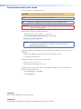
Conventions Used in this Guide
In this user guide, the following are used:
CAUTION: A caution indicates a potential hazard to equipment or data.
NOTE: A note draws attention to important information.
TIP:
A tip provides a suggestion to make working with the application easier.
WARNING: A warning warns of things or actions that might cause injury, death, or
other severe consequences.
Commands are written in the fonts shown here:
^AR Merge Scene,,Op1 scene 1,1 ^B 51 ^W^C
[01] R 0004 00300 00400 00800 00600 [02] 35 [17] [03]
E X! *X1&* X2)* X2#* X2! CE}
NOTE: For commands and examples of computer or device responses mentioned
in this guide, the character “0” is used for the number zero and “O”
represents the capital letter “o.”
Computer responses and directory paths that do not have variables are written in the font
shown here:
Reply from 208.132.180.48: bytes=32 times=2ms TTL=32
C:\Program Files\Extron
Variables are written in slanted form as shown here:
ping xxx.xxx.xxx.xxx —t
SOH R Data STX Command ETB ETX
Selectable items, such as menu names, menu options, buttons, tabs, and field names are
written in the font shown here:
From the File menu, select New.
Click the OK button.
Copyright
© 2012 Extron Electronics. All rights reserved.
Trademarks
All trademarks mentioned in this guide are the properties of their respective owners.
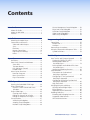
Contents
Introduction............................................. 1
About this Guide.............................................. 1
About the JMP 9600......................................... 1
Features............................................................ 3
Installation............................................... 6
Mounting the Media Player............................... 6
Connections and Features................................. 6
Video and Audio Outputs............................. 7
Sync.............................................................. 8
LAN Ports...................................................... 9
Remote Control Port................................... 10
Digital Inputs and Relays............................. 11
Power......................................................... 12
License Management Setup Dialog Box....... 50
Player Info Setup Dialog Box....................... 50
Serial Port Setup Dialog Box........................ 51
Video Setup Dialog Boxes........................... 52
About Setup Dialog Box.............................. 54
Programming Guide............................... 55
Control Ports.................................................. 55
Remote Port 1............................................. 55
LAN Ports.................................................... 55
Host-to-Player Instructions.............................. 57
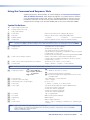
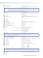
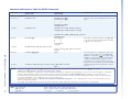
Using the Command and Response Table........ 58
Symbol Definitions...................................... 58
Detailed System Interaction.................. 76
Operation................................................ 13
Definitions...................................................... 13
Front Panel Controls and Indicators................. 14
Status LEDs................................................. 14
Transport Buttons........................................ 15
LCD and Menu Controls............................. 15
Encoder knob............................................. 15
Menu System Overview................................... 16
Power-on Sequence.................................... 16
Menu System Flow...................................... 16
Play a Presentation...................................... 36
HTML Operation...................................... 37
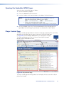
Opening the Embedded HTML Pages.............. 38
Player Control Page......................................... 38
Channel 1 and 2 Control and Status
Windows................................................... 39
Playlist Editor Page.......................................... 43
Creating a New Playlist............................... 43
Editing the Contents of a Playlist................. 44
Editing the Properties of a Playlist................ 46
Setup Functions.............................................. 47
Audio Setup Dialog Box.............................. 47
Autoplay Setup Dialog Box.......................... 48
Network Setup Dialog Boxes....................... 48
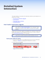
Data Transfer and Firmware Upgrade.............. 76
Starting the FileZilla FTP Utility..................... 76
Loading Media Folders to
the Media Player........................................ 78
Deleting Folders and Individual Files from
the Media Player........................................ 79
Loading and Updating firmware.................. 80
Synchronization.............................................. 83
Connections for Synchronized
Multi-player Operation............................... 84
Configuring LTC for Synchronized
Multi-player Operation............................... 88
Configuring Genlock for Synchronized
Multi-player Operation............................... 92
High Frame Rate......................................... 93
Using Digital Inputs and Relays....................... 93
Optically-isolated Digital Inputs................... 94
Relay Contacts............................................ 95
Applicable MSVPP Commands.................... 95
Encoding Guidelines....................................... 96
Encoding and Packaging Overview.............. 97
Supported Video Formats............................ 98
JPEG-2000 Restrictions................................ 99
JMP 9600 Media Player • Contents
v
Mounting and Maintenance................ 100
Reference Information......................... 111
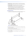
Mounting the Media Player........................... 100
Ventilation Guidelines............................... 100
Tabletop Use............................................. 100
Rack Mounting......................................... 100
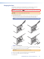
Cleaning the Air Filters.................................. 102
Changing the Fuses...................................... 103
Troubleshooting a High Temperature............. 104
Battery Precautions....................................... 104
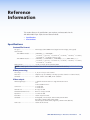
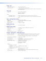
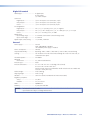
Specifications................................................ 111
Part Numbers................................................ 114
JMP 9600 Part Numbers............................ 114
Included Parts........................................... 114
Optional Accessories and Replacement
Filters....................................................... 114
Cables...................................................... 115
Ethernet Connection............................ 105
Ethernet Link................................................ 105
Default IP Address..................................... 105
Pinging to Determine the IP Address......... 106
Pinging to Determine the web IP Address.. 106
Configuring the Media Player for Network use
via the ARP Command............................. 107
Connecting as a Telnet Client.................... 108
Telnet Tips................................................. 108
Subnetting — A Primer................................. 109
Gateways.................................................. 109
Local and Remote Devices......................... 109
IP Addresses and Octets............................ 109
Subnet Masks and Octets.......................... 110
Determining Whether Devices are on the Same
Subnet..................................................... 110
JMP 9600 Media Player • Contents
vi
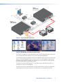
Introduction
• About this Guide
• About the JMP 9600
• Features
About this Guide
This guide contains installation, configuration, and operating information for the following
Extron® media players:
• JMP 9600 HD – JPEG 2000 Media Player HD
• JMP 9600 HD 128 – JPEG 2000 Media Player HD 128 GB SSD
• JMP 9600 2K – JPEG 2000 Media Player 2K
• JMP 9600 2K 128 – JPEG 2000 Media Player 2K 128 GB SSD
NOTE:
In this manual, the terms “JMP 9600” and “media player” refer to any model
unless otherwise specified.
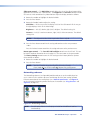
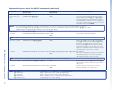
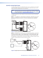
About the JMP 9600
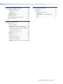
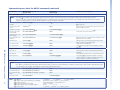
The JMP 9600 Media Player (see figure 1, on the next page) is a high quality video and
audio playback device that provides one or two video playback channels. It meets the
most demanding 3D and stereoscopic applications as well as more traditional single
display requirements. Depending on the model, the player supports video playback of the
JPEG 2000 (2k) and high definition (HD) standards. SSD models use solid state memory
rather than magnetic hard drives, but are otherwise identical.
The JMP 9600 also provides 16 channels of uncompressed digital audio in the Audio
Engineering Society (AES)/European Broadcasting Union (EBU) standard, commonly called
AES3, on BNC connectors.
The JMP 9600 plays visually lossless Digital Cinema Package (DCP) files. These files include
video, audio, and other data elements that are encoded to the Digital Cinema Initiatives
(DCI) specification. DCI is a standard architecture for digital cinema systems.
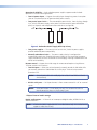
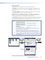
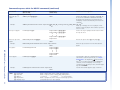
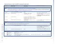
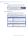
The JMP 9600 also features a built-in, full color video LCD display that serves as the interface
for local control and also functions as a local “confidence” monitor for video output during
playback. The LCD can show the graphical user interface (GUI), the video playback display, or
both simultaneously (see figure 2, on the next page). You can control the amount of both
video streams (the “alpha blend”) displayed in the LCD.
JMP 9600 Media Player • Introduction
1
Extron
JMP 9600 2K
HD Video Player
Show Control
System
Ethernet
Switch
Linear Time
Code
C
LT
S
UT
TP
96
P
OU
EO
I 2
L VIDSD
TA HD
GI
DI
1
DV
I-I-2
OU
N
LA
L
TA
DIGI
DIO
AU T
7-8 OU
N
LA
N
LA
N
DV
S
UT 4 L INP3 - +
+
I-I-1
+
LA
TE
5-6
N
TP
R3
HZ
/60
, 50 S.
-1A SE
0.4 FU
C, 0V
VA 24
40 AH
0-2
10 LY: F2
T:
PU ON
IN E
US
0
-16
15
-14
13
1
WE
PO
12V
R
R1
NC
C
OU
NC
NO
NC
Linear Time
Code
NC
C
NO
NC
NO
R2
C
2
RE
3-4
1-2
9-1
LAY
RE
C
MO
LA
Sync Generator Timing
Matches HD Content Format
ITA
DIG2
1- +
R4
S
UT
JM
X
T
OU
Ethernet
12V MA
.5A
IN
T
K
OC
NL
GE
00
R
WE
PO
IN
CK
LO
Ethernet
TE
1
MO
RE
-12 2
11
N
LA
Dual Link
HD-SDI
Extron
JMP 9600 2K
HD Video Player
T
URS
CKB
5
BLA
X
L
IO
AUD
1
6
1
4
2
ON
ARS
2
3
ORB
COL
Genlock
-10
PAL
WE
12V MA
.2A
+4
NTSC
BLACKBURST
3
6A
T AND
G
URS
BBCKBTOR
BLA ERA
GEN
1 KHZ
IO R
AUD
R
PO
Genlock
C
LT
IN
CK
LO
IN
T
OU
T
K
OU
OC
NL
GE
S
UT
00
TP
96
P
OU
EO
I 2
L VIDSD
TA HD
GI
DI
1
DV
I-I-2
JM
L
TA
DIGI
DIO
AU T
7-8 OU
DV
+
TE
1-2
0
-14
-12 2
11
N
LA
WE
PO
12V
R
R1
NC
C
NC
NC
NC
C
NO
NC
NO
ITA
DIG2
1- +
2
MO
-16
15
13
1
C
R4
RE
3-4
9-1
S
UT 4 L INP3 - +
+
I-I-1
5-6
HZ
/60
, 50 S.
-1A SE
0.4 FU
C, 0V
VA 24
40 AH
0-2
10 LY: F2
T:
PU ON
IN E
US
LAY
RER2
S
UT
TP
OU R3 NO
TE
MO
RE
1
Dual Link
HD-SDI
Large Venue Projectors
16 AES/EBU
Digital Audio Ouputs
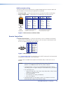
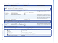
Figure 1. Typical JMP 9600 Application
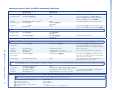
Graphical User Interface
Video Playback Display
Blended Display
Figure 2. Blended GUI and Video Playback Display
The Linear Time Code (LTC), Lock (JMP 9600 2K only), and Genlock connectors enable multiunit synchronization and integration into the most demanding applications.
The JMP 9600 manages all program material in the digital environment to ensure that image
quality is maintained regardless of the number of times a file is displayed or copied. When
integrated into a computer network, the JMP 9600 can be accessed from remote locations
for ease of loading content and remote control.
The player can be operated remotely by a PC or control system connected to an RS-232
serial port or to either of two LAN ports.
The player is housed in a rack-mountable, 2U high metal enclosure. With the included rack
mounting brackets installed, the player can be mounted in any standard 19-inch rack.
JMP 9600 Media Player • Introduction
2
Features
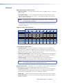
Digital video outputs: HD-SDI or DVI-I —
• Two DVI-I outputs — One connector per output channel supports 8-bit 4:2:2 sampled
RGB or YCrCb.
• Two HD-SDI outputs — Can be configured as one dual link HD-SDI output or two
single link HD-SDI outputs (one per channel — two single link outputs are available in
1-channel output mode only).
NOTE:
With HD-SDI 4:4:4 sampling, both video outputs (HDSDI-1 and HDSDI-2)
are connected to the display.
• The dual outputs of either format can operate as two independent sources or as two
synchronized outputs.8
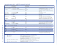
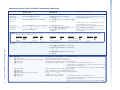
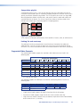
Supports multiple video resolutions —
Frames per second (Fps)
Resolution
23.98
24
25
29.97
30
48
50
59.94
60
•
•
•
•*
JMP 9600 HD and JMP 9600 2K
1280 x 780
•
1920 x 1080i
•
JMP 9600 2K only
1920 x 1080i
•
1920 x 1080p
•
•
•
•
•
•
•
•
•
2048 x 1080p
•
•
•
•
•
•
•
•
•
* 4:2:2 only on HD model
1- and 2-channel output modes —
• 2-channel output — Each channel outputs a video image that can be completely
different from the video on the opposite channel, though both must be of the same
resolution and frame rate. The video signal for each channel is available on two outputs;
both the HD-SDI output and DVI-I output for that channel.
• 2-channel locked output — Each channel outputs a video signal that is synchronized
to the video on the opposite channel. The video signal for each channel is available on
two outputs; both the HD-SDI output and DVI-I output for that channel.
• 1-channel output — Outputs an analog or digital signal. The video signal for the
channel is available on two outputs; both the HD-SDI output and DVI-I output.
NOTE:
For two clips to load properly in 2-channel or 2-channel locked mode, both
must be created at the same resolution and frame rate.
Operational flexibility — Operations such as input/output selection and setting of presets
can be performed using a variety of local and remote control mechanisms:
• Front panel controller — Intuitive front panel user interface with an LCD display and
a rotary encoder for easy local control of the player. The video portion of a playing
presentation can be displayed in the LCD as a confidence monitor.
• HTML pages — Built-in pages for controlling the player from anywhere in the world.
• MSVPP commands — A set of basic commands that provide simple control through a
control system or PC
JMP 9600 Media Player • Introduction
3
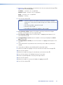
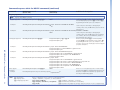
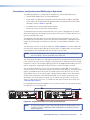
Operational reliability — Dual redundant power supplies support round-the-clock
operation in mission-critical applications.
• Two AC power inputs — Support the media player through any power interruption
short of a simultaneous loss of power on both power sources.
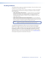
• Two power input circuits — The two complete power circuits, from the plug, through
fuse, switch, and power supply, to the power insertion onto the power distribution
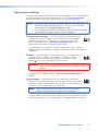
plane, are separate and independent from each other (see figure 3).
AC
Power
AC
Power
Power
Supply
Power
Supply
Figure 3. Redundant Power Supply Backs Up Primary
• Two power supplies — The two 100 VAC to 240 VAC, 50-60 Hz power supplies
provide worldwide power compatibility.
• Mutually redundant circuits — The power supply circuitry is configured to
automatically switch over. Should either power supply fail, the remaining, hot power
supply immediately assumes the load of the failed supply, meaning zero downtime and
no loss of functionality.
Remote control — Support for a wide range of remote control options using Ethernet
TCP/IP or serial RS-232 interfaces.
• Two LAN ports — Allow you to simultaneously remotely control the JMP 9600 while
you remotely upload new audio/video files to the player. Two levels of password
protection exist.
NOTE:
Two LAN ports allow the media player to reside on two different subnets
simultaneously.
• RS-232 serial ports — Serial port Remote 1 allows remote control via a PC or a control
system.
NOTE:
Serial port Remote 2 is for factory use only. The customer or end user
cannot control the player via the Remote 2 port.
1 TByte of internal media storage
Digital audio output — 16 channels of uncompressed digital audio; AES/EBU 24-bit at
48 kHz or 96 kHz
NOTE:
16 channel audio is supported with 4:4:4 video format only. 4:2:2 video formats
support 8 audio channel only.
JMP 9600 Media Player • Introduction
4
Linear Time Code feature — Supports strict system timing control.
ESGEN and MSGEN Genlock capability — JMP 9600 2K units are capable of multi-unit
synchronous operation.
NOTE:
ESGEN and MSGEN Genlock are proprietary sync signals that are native
to Electrosonic® products that have been acquired by Extron and to older
Electrosonic products.
Multi-screen capable — Multiple JMP 9600 2K units can be locked together for multiscreen applications
General purpose input/output show control — Four optically-isolated inputs and 4
changeover relay contact outputs provide enhanced show control.
Permanent, rechargeable battery — The media player has a rechargeable lithium battery
to track time of day when power is disconnected.
CAUTION: Non-Extron personnel must not attempt to remove the battery. Doing so will
void the warranty.
WARNING: Service note to Extron personnel — There is a danger of explosion if the
battery is incorrectly replaced. Replace it only with the same or equivalent
type recommended by the manufacturer. Dispose of used batteries
according to the instructions of the manufacturer.
Rack mountability
Front panel security lockout modes (Executive mode) — If a player is installed in an
open area, where operation by unauthorized personnel may be a problem, a security lockout
mode can be implemented via remote control (RS-232 or Ethernet). When the front panel
is locked, no front panel controls are functional and another remote control operation is
required to unlock the front panel controller and make the front panel fully operational.
JMP 9600 Media Player • Introduction
5
Installation
This sections details the installation of the JMP 9600, including:
• Mounting the Media Player
• Connections and Features
Mounting the Media Player
CAUTION: Installation and service must be performed by authorized personnel only.
Detailed mounting instructions can be found in the “Mounting and Maintenance“
section. The 2U high, JMP 9600 can be placed on a tabletop or mounted on a rack shelf.
Use the included hardware for rack mounting.
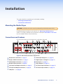
Connections and Features
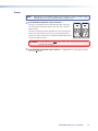
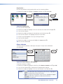
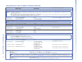
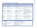
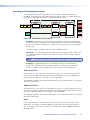
All system connections are on the back of the media player (figure 4).
13
3
2b
1a
2b
5
1b 4
6
INPUT: 100-240VAC, 0.4-1A, 50/60HZ
USE ONLY: F2 AH 240V FUSES.
JMP 9600
1-2
9-10
12
3-4
11-12
1 LAN 2
7
5-6
13-14
7-8
DIGITAL
AUDIO
OUT
LOCK
DIGITAL VIDEO OUTPUTS
HDSDI
1
2
DVI-I-1
GENLOCK
LTC
IN
IN
OUT
OUT
DVI-I-2
15-16
REMOTE 1
8
REMOTE 2
For Factory
Use only
DIGITAL INPUTS
1
2
3
4
+ - + + - + -
POWER
12V
9
10
RELAY OUTPUTS
R1
NC C NO NC
R2
R3
C NO NC C
R4
NO NC C NO
11
Figure 4. Rear Panel Connections and Features
a Output DVI-I connectors (see page 7)
b Output HD-SDI connectors (see page 7)
c Audio Output connectors (see page 7)
d Genlock Input connector (see page 8)
e Lock Input and Output connectors (see page 8)
f LTC Input and Output connectors (see page 8)
g LAN ports — (see page 9)
h Remote (RS-232) port 1 (see page 10)
i Digital Inputs 1 through 4 (see page 11)
j Power port (see page 11)
k Relay Outputs (see page 11)
l AC Power Input connectors (see page 12)
m AC Power Input switches (see page 12)
JMP 9600 Media Player • Installation
6
Video and Audio Outputs
a Digital Video Outputs, DVI-I connectors — Connect one or two DVI displays to
the DVI-I-1 and DVI-I-2 connectors for the direct digital image and RGB video output.
Figure 5 defines the pinout for the DVI protocol.
1
8
C1
C2
17
24
C3
C4
9
Pin
C5
Female Connector
Male Connector (cable)
Signal
Pin
Signal
Pin
Signal
1
TMDS data 2–
9
TMDS data 1–
17
TMDS data 0–
2
TMDS data 2+
10
TMDS data 1+
18
TMDS data 0+
3
TMDS data 2/4
shield
11
TMDS data 1/3
shield
19
TMDS data 0/5
shield
4
TMDS data 4–
12
TMDS data 3–
20
TMDS data 5–
5
TMDS data 4+
13
TMDS data 3+
21
TMDS data 5+
6
DDC clock
14
+5 V power
22
TMDS clock
Shield
7
DDC data
15
Ground (+5 V)
23
TMDS clock+
8
Analog V sync
16
Hot Plug Detect
24
TMDS clock–
C1
Analog red
C3
Analog blue
C5
Analog RGB Gnd
C2
Analog green
C4
Analog H sync
Figure 5. DVI Output Connectors
NOTES: • Both DVI connectors can output single-link DVI (digital) video and
traditional analog video.
• DVI signals run at a very high frequency and are especially prone to errors
caused by bad video connections, too many adapters, or excessive cable
length. To avoid the loss of an image or jitter, follow these guidelines:
• Do not exceed 16.4 feet (5 meters) of standard cable length.
• Extron IN9700 cable can exceed 16.4 feet for single link of DVI-D.
• Use only cables designed for DVI signals. Use of non-DVI or nonHDMI cables or modified cables can result in a missing video output.
• Limit or avoid the use of adapters.
Two DVI-A-to-VGA adapters are included with the media player that allow you to
accomodate an analog-only output on more standard connectors.
b Digital Video Outputs, HD-SDI connectors — Connect one or two HD-SDI
1
devices to the HDSDI-1 and HDSDI-2 BNC connectors.
NOTE:
A dual-link HD-SDI output requires using both connectors for a single video
signal and selecting the mode, either on the front panel (see “Video
submenu“ in the “Operation” section) or via an MSVPP command (see the
setHdsdimode command in the “Programming Guide” section).
c Digital Audio Output connectors — Connect devices that can receive and
decode AES3-encoded audio to these 8 BNC connectors to receive up to
16 channels of audio.
1-2
NOTES: • The AES3 protocol supports two channels of audio on one BNC connector.
• Media files that are encoded with 4:2:2 subsampled video support only
eight channels of audio. With 4:2:2 video:
• Audio channels 1 through 8 are associated with video channel 1.
• Audio channels 9 through 16 are associated with video channel 2.
JMP 9600 Media Player • Installation
7
Sync
In sync-critical applications, the media player can use one of two possible external sync
signals, Genlock or Lock, in addition to the always-available Linear Time Code (LTC), to
synchronize itself with other devices within a larger system. The media player can generate
two of the sync signals to other devices.
NOTES: • Use only one of the Genlock and Lock sync types (items d and e) available.
• Ensure that the resolution and frame rate of the applied genlock or lock input
signal matches the resolution and frame rate of the clip to be played.
d Genlock Input connector — Connect an external genlock signal to this
GENLOCK
BNC connector for genlocking the video signal in broadcast or other sync-critical
NTSC, PAL, or HDTV tri-level applications.
Use a tee connector or distribution amplifier to connect any downstream
equipment that requires genlocking.
Snap one of the included ferrite beads on this cable, as close to the unit as practicable.
e Lock Input and Output connectors —
LOCK
IN
NOTES: • The Lock connectors support ES genlock and MS 9200 genlock,
which are proprietary sync signals that are native to Electrosonic®
products that have been acquired by Extron and to older
Electrosonic products.
• These connectors are present on all units but only JMP 9600 2K
units support ES genlock and MS genlock.
• When using ES genlock or MS genlock, the video signal
resolution and frame rate must match on all players.
OUT
Lock Input connector — Connect an external ES genlock or MS genlock sync signal to
this 6-pin mini-DIN connector for the media player to function as a sync slave of another
device.
Lock Output connector — Connect any downstream equipment that requires an
ES genlock sync signal to this 6-pin mini-DIN connector to either route the external sync
signal throughout the system or for the media player to function as a sync master.
Snap one of the included ferrite beads on each Lock cable, as close to the unit as
possible.
f LTC (Linear Time Code) Input and Output connectors —
LTC
LTC Input connector — Connect an external LTC sync signal to this RCA
connector for the media player to function as a sync slave of another device.
IN
OUT
LTC Output connector — Connect any downstream equipment that requires
an LTC sync signal to this RCA BNC connector to either route the external sync signal
throughout the system or for the media player to function as a sync master.
Snap one of the included ferrite beads on each LTC cable, as close to the unit as
possible.
JMP 9600 Media Player • Installation
8
LAN Ports
g LAN ports — If desired, for IP control of the media player and content
transfer, connect the player to a PC or to an Ethernet LAN, via either of these
RJ-45 connectors. You can use a PC to control the networked player with MSVPP
commands from anywhere in the world. You can also control the player from any PC via
the built-in HTML pages or MSVPP commands and the Extron DataViewer utility.
Link (green) LED indicator — The Link LED indicates that the player is properly
connected to an Ethernet LAN. This LED should light steadily.
Act (yellow) LED indicator — The Act LED indicates transmission of data packets on
the RJ-45 connector. This LED should flicker as the player communicates.
NOTES: • Extron recommends that each LAN port have a unique IP address.
• The factory default IP and netmask (subnet mask) addresses are as
follows:
LAN 1:
IP address: 192.168.254.254
Netmask address: 255.255.0.0
LAN 2:
IP address: 192.168.254.253
Netmask address: 255.255.0.0
Both ports:
Gateway address: 0.0.0.0
DHCP: Off
• Two LAN ports allow the media player to reside on two different subnets
simultaneously.
Cabling
It is vital that your Ethernet cables be the correct cable type and that they be properly
terminated with the correct pinout. Ethernet links use Category (CAT) 5e or CAT 6,
unshielded twisted pair (UTP) or shielded twisted pair (STP) cables, terminated with RJ-45
connectors. Ethernet cables are limited to a length of 328 feet (100 m).
NOTES: • Do not use standard telephone cables. Telephone cables do not support
Ethernet or Fast Ethernet.
• Do not stretch or bend cables. Transmission errors can occur.
The cable used depends on your network speed. The player supports the following Ethernet
formats half-duplex and full-duplex Ethernet protocols, using the following cable:
• 10 Mbps (10Base-T — Ethernet) requires CAT 3 UTP or STP cable at a minimum.
• 100 Mbps (100Base-T — Fast Ethernet) requires CAT 5 UTP or STP cable at a minimum.
• 1000 Mbps (1000Base-T — Gigabit Ethernet) requires CAT 5 UTP or STP cable at a
minimum.
Snap one of the included ferrite beads on each network cable, as close to the unit as
practicable.
JMP 9600 Media Player • Installation
9
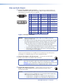
RJ-45 connector wiring
The Ethernet cable can be terminated as a straight-through cable or a crossover cable and
must be properly terminated for your application (see figure 6).
• Crossover cable — Direct connection between the computer and the media player
• Patch (straight) cable — Connection of the media player to an Ethernet LAN
Crossover Cable
Pins:
12345678
Pin
Insert Twisted
Pair Wires
End 1
Wire color
Pin
End 1
Wire color
End 2
Wire color
1 White-green
White-orange
1 White-orange
White-orange
2 Green
Orange
2
Orange
Orange
3 White-orange
White-green
3 White-green
White-green
4 Blue
Blue
4 Blue
Blue
5 White-blue
White-blue
5 White-blue
White-blue
6 Orange
Green
6
Green
7 White-brown
White-brown
7 White-brown
White-brown
8 Brown
Brown
8 Brown
Brown
T568A
RJ-45
Connector
End 2
Wire color
Straight-through Cable
T568B
A cable that is wired as T568A at one end
and T568B at the other (Tx and Rx pairs
reversed) is a "crossover" cable.
Green
T568B
T568B
A cable that is wired the same at both ends is
called a "straight-through" cable, because
no pin/pair assignments are swapped.
Figure 6. RJ-45 Connector and Pinout Tables
Remote Control Port
h Remote (RS-232) port 1 — Connect a host device, such as a computer, touch panel
control, or RS-232 capable PDA to the player via this male 9-pin D connector for serial
RS-232 (see figure 7) control or pass-through.
1
6
5
9
Pin RS-232 Function
1
— Not used
2
TX Transmit data
3
RX Receive data
4
— Not used
5
Gnd Signal ground
6
— Not used
7
— Not used
8
— Not used
9
— Not used
Figure 7. Remote 1 Port
See “Programming Guide“ for definitions of the MSVPP commands (serial commands
to control the media player via this connector).
Snap one of the included ferrite beads on the Remote cable, as close to the unit as
possible.
NOTES: • Unlike products that were designed by Extron, former Electrosonic
products use a male connector. You may need an adapter.
• Serial port Remote 1 can be set to ControlMSVPP (control the player),
Passthrough (pass the signals through to a controlled device), or Disabled.
• The media player can:
• Operate at 300, 600, 1200, 1800, 2400, 4800, 9600, 19200, 38400,
57600, or 115200 baud rates
• Use 7 or 8 data bits
• Use no parity, even parity, or odd parity.
• Use 1 or 2 stop bits
• Serial port Remote 2 is for factory use only. The customer or end user
cannot control the player via the Remote 2 port.
JMP 9600 Media Player • Installation
10
Digital Inputs and Relays
The Digital Inputs and Relays ports provides optically-isolated digital inputs and relay outputs
that can be controlled by the show control software. See the “Programming Guide“
section for the MSVPP commands that activate or are issued by the these ports.
NOTES: • By factory default, automatic reporting of Digital Inputs 1 through 4 is
disabled. To enable reporting, use the Set input trigger on MSVPP
command (see the “Programming Guide” section).
• Use a single cable for all inputs and relay ports and snap one of the included
ferrite beads on the cable, as close to the unit as possible.
i Digital Inputs 1 through 4 — These inputs allow the media player to sense
a discrete signal, such as change in a switch position. Connect the desired
discrete input line to the unit via two poles (+ and –) of a 3.5 mm 4-pole
captive screw connector (see “Optically-isolated Digital Inputs”, on
page 94, for an illustration of a typical input connection).
1
2
+ - + -
The media player issues an MSVPP message on Remote port 1 when it detects a
change of state on the digital inputs, prompting the connected device to respond as
appropriate.
j Power — This port provides +12 VDC power at up to 1.8 A, typically for use
with Digital Inputs 1 through 4 (item i) above. The power is internally
protected. Connect the device requiring power to two poles (12V and
ground [ ]) of a 3.5 mm 4-pole captive screw connector.
POWER
12V
WARNING: 12 VDC is always present on this port when the media player is powered
on. Ensure that no conductive material comes into contact with these
terminals.
A typical use of this voltage is shown in “Optically-isolated Digital Inputs,” on
page 94.
k Relay Outputs — These ports are four sets of NO and NC relay contacts.
R1
NC C NO NC
Connect an external device that you want to be able to switch on or off to the
player via three poles (normally closed [NC], common [C], and normally open
[NO]) of the 3.5 mm 4-pole captive screw connectors.
NOTE:
Relays R1 and R4 each are on a single captive screw connector.
Relays R2 and R3 each span two captive screw connectors.
The player toggles the relay on or off in response to an MSVPP signal from the device
connected on Remote port 1 or either LAN port, see “Relay Contacts“ on page 95.
JMP 9600 Media Player • Installation
11
Power
NOTE:
Although the unit performs reliably while running on a single AC power supply,
doing so defeats the dual-redundant power supply feature.
l Dual Redundant AC Power Input connectors —
Connect a standard IEC power cord between one rear panel
AC Power Input connector and a 100 to 240 VAC, 50-60 Hz
power source.
Connect a second IEC power cord between the remaining AC
Power Input connector and either an uninterruptible power
source or a power source that is completely independent from
the primary power source.
WARNING: Physically disconnect both power cables from the player before opening
the case for servicing.
m Dual Redundant AC Power Input switches — Toggle both AC Power Input switches
to the on ( ) position.
JMP 9600 Media Player • Installation
12
Operation
This section describes the front panel operation of the JMP 9600, including:
• Definitions
• Front Panel Controls and Indicators
• Menu System Overview
Definitions
The following terms, which apply to Extron media players, are used throughout this
manual:
• Digital Cinema Package (DCP) — A folder that contains all of the files necessary for
the JMP 9600 to play a presentation. This folder can include reel files (video images
and audio data), subtitle files, the composition playlist (CPL), and the associated
packing list and asset map. All of these file types are detailed below and are encoded
to the Digital Cinema Initiatives (DCI) specification.
NOTE:
All of the files within the DCP are automatically created when using the
Extron JPEG 2000 Encoding Software (see “Encoding Guidelines” in the
“Detailed System Interaction” section).
• Reel — A reel is a file that contains either compressed video content or
uncompressed audio content. These files have the *.mxf file extension, for example
reel_1_video.mxf. Reels are typically 10 to 20 minutes long, so a larger presentation
may consist of multiple video and audio reels.
• Composition Playlist (CPL) — An xml file that contains all of the information
on how the files for a specific presentation should be played back, including the
filenames and locations of the reels and how the audio and subtitles are synchronized
with the picture. The CPL can specify one video reel and one audio reel or multiple
reels of both types.
• Clip — The video and audio material content specified by a CPL file. The terms “clip”
and “DCP” can be used interchangeably.
• Asset map file — A file that is similar to the CPL file, but the asset map also lists the
frame rate and duration of the clip.
• Packing list file — A file that contains information and identification about each of
the individual files that are delivered in a DCP.
• Playlist — An xml file that can be the name of a single DCP presentation (a clip) or a
sequential list of clips. Playlists must contain DCPs that are all of the same resolution,
color space, frame rate, and number of audio channels to load successfully in the
JMP 9600.
NOTE:
Pay attention to the difference between a “playlist” and a “composition
playlist.”
JMP 9600 Media Player • Operation
13
Pre-roll period — A programmable interval before the presentation starts. As an example,
pre-roll might allow audience members to take their seats after an announcement that the
show has begun.
Post-roll period — A programmable interval after the presentation ends. Select the Stop At
option to set a stop point for the timecode and for the screen to go black. As an example,
post-roll might allow the house lights to gradually brighten. Post-roll is also sometimes
known as “run-on.”
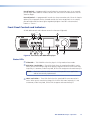
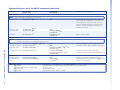
Front Panel Controls and Indicators
All JMP 9600 controls and indicators are on the front panel (figure 8).
Not
2 Used 3
1
11
JMP 9600
JPEG2000 MEDIA PLAYER
VIDEO
DISK DRIVE
1
2
3
LAN
4
1
PREV
2
ENTER
4
6
5
7
8
9
10
12
13
Figure 8. Front Panel, JMP 9600 Media player
Status LEDs
a Video LED — This LED blinks when the player is in Play mode or Pause mode.
b Disk Drive 1 and 2 LEDs — These LEDs flash when the associated hard disk is active.
When you are transferring a large file or playing a high bit rate file the LEDs flash more
frequently. It is common, under heavy load, for the LEDs to appear to be continuously lit.
NOTE:
The Disk 3 and Disk 4 LEDs are reserved for possible future applications
and are not currently implemented.
c LAN 1 and 2 LEDs — These LEDs flash when the associated Ethernet connection is
active. When you are transferring a large file the LEDs flash more frequently. It is not
uncommon, under heavy load, for the LEDs to appear to be continuously lit.
JMP 9600 Media Player • Operation
14
Transport Buttons
d Play/Pause (
) button — Press this button to start the currently selected CPL or clip
file or pause a currently playing presentation while leaving the image displayed.
e Stop (
) button — Press this button to stop the currently playing presentation. When
you press Play again, the presentation starts over from the beginning.
f Previous clip (
) button — Press this button to load the previous CPL or clip file in
the playlist. The button has no function if no playlist is loaded (using the menu controls).
g Frame mode button (
) — Press this button and then rotate the encoder knob
(item m) to step frame-by-frame through the CPL or clip file while the player is in play
mode.
h Shuttle mode (
) button — Press this button and then rotate the encoder knob
(item m) to “shuttle” backwards and forwards through the CPL or clip file, at a rate
controlled by the encoder knob.
NOTE:
The audio portion of the clip is active only when the playback speed is +1.0
(normal forward speed).
i Next clip (
) button — Press this button to load the next CPL or clip file in the
playlist. The button has no function if no playlist is loaded (using the menu controls).
LCD and Menu Controls
j LCD screen and confidence monitor — The LCD display the user interface for local
control. The screen can also display a presentation as the player outputs it on its video
output connectors. The alpha-blend feature allows you to display a mix of the video that
is playing and the user interface simultaneously.
k Previous button — Press this button to return to the previously displayed menu or
page.
l Enter button — Press this button to initiate or activate a selected function.
Encoder knob
m Encoder knob — Rotate this knob to navigate the menu system. Rotate this knob
when frame mode and shuttle mode are selected to operate those features.
JMP 9600 Media Player • Operation
15
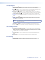
Menu System Overview
Power-on Sequence
Plug either or both power cords into power sources and turn on ( ) one or both rear panel
power switches. When AC power is applied, the media player performs a self-test that blinks
all of the front panel buttons several times and then displays the LCD start-up screen while
it continues to load the operating system (see figure 9). After approximately 40 seconds,
the LCD window displays the main menu screen. An error-free power-up self-test sequence
leaves all of the buttons except Stop unlit and the LCD window displaying the main menu.
40 sec.
Power
on
Figure 9. LCD Power up Screen and Main Menu
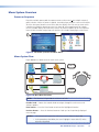
Menu System Flow
Figure 10 shows a flowchart of the main menu system.
PREV
Ch. 1 Status
Ch. 2 Status
Settings
Lock
Help
System Status
(License
Keys)
ENTER
(About)
Figure 10. Main Menu Flowchart
NOTE:
The elements in figure 10 are not drawn to scale.
Encoder knob — Rotate the encoder knob to navigate through the main menu and
submenu options.
Enter button — Press the Enter button to activate the highlighted function.
Previous button — Press the Previous button to “back up” to the previously displayed
menu or page.
NOTES: • You cannot back up past the main menu screen shown in figure 10.
• In the procedures that follow, the term “highlight” means blue fill, unless
otherwise described.
JMP 9600 Media Player • Operation
16
Channel status menus
NOTES: • Channel 2 Status is displayed in the main menu (figure 10) and available for
selection only in 2-channel output mode and 2-channel locked output mode,
both of which can be selected in the Settings > Video submenu.
• The Channel 1 Status and Channel 2 Status are identical, except where noted.
Figure 11 shows an overview of the Channel Status screen and the available settings.
Figure 11. Channel Status Menu
The LCD shows the current state of the channel 1, including the loaded clip and playlist (if
applicable) and whether the presentation is playing, paused or stopped. The screen also
shows two counters and a static display that display the time of specific functions of the
time as hour:min:sec:frame:
Tc (Timecode) — The Timecode counter shows the current point in time within the loaded
program. The Timecode counter includes the pre-roll, roll, and post-roll periods.
Lock indicator ( ) — The lock indicator, when displayed, indicates the video that is
playing is synchronized with an external genlock signal.
Fr (Frame) — The Frame counter shows the current point in time within the currently
loaded playlist or clip; the roll period only.
Dur (Duration) — The Duration display shows the entire run-time of the currently loaded
playlist or clip. This is a static display only.
NOTE:
The frame field of the Tc and Fr counters is not updated during playback; only
the hour:min:sec fields are active. The Time count and Frame counters show the
frame number when paused, in Frame mode, or in shuttle mode.
JMP 9600 Media Player • Operation
17
Playlist and Clip fields
These fields display whether a playlist or clip is loaded. Empty fields indicate that no playlist
or clip is loaded. They also are used with menu controls to load a playlist or clip.
Select and load a playlist or clip as follows:
NOTES: • You must have created one or more playlists using the HTML pages before
any are available for selection to select (see “Playlist Editor Page“ in the
“HTML Operation” section).
• Ensure that the media player is configured for 1-channel output before
attempting to load 4:4:4 chroma subsampled content. If the player is
configured for 2-channel output mode and 2-channel locked output mode,
these formats will not load. Use the Settings > Video submenu to check
the video mode and change it if necessary.
• In 2-channel locked output mode, the files for the two channels must have
the same number of frames, resolution, bit depth, and number of audio
channel and must use 4:2:2 chroma subsampling. If these conditions are not
met, the files will not load.
• The player must be correctly configured for the clip or playlist that you select
using the Settings > Video submenu, or else the player does not load the
selected clip or playlist and the LCD reports ERROR.
• If you cannot get a clip to load, see “Setting the clip or playlist to
autoplay and view clip info“ in the “HTML Operation” section to view the
properties of the clip, which can help reveal the problem.
• If you load a new clip with a different resolution and frame rate than the
currently loaded clip, it can take up to 4 seconds before it is ready to play.
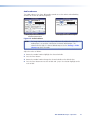
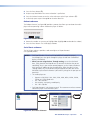
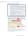
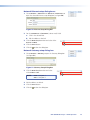
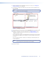
1. Rotate the encoder knob as necessary to highlight the
Playlist field or Clip field as shown at right.
2. Press the Enter button. The Select a playlist screen (a list of playlist files) or Select a clip
folder screen (a list of DCP folders) appears (see figure 12).
3
3
Select a playlist
Select a clip
Figure 12. Select a Playlist Screen and Select a Clip Folder Screen
3. Rotate the encoder knob as necessary to highlight
the desired playlist file or clip folder.
4. Press the Enter button.
When loading a playlist — The LCD returns to the Channel Status screen with the
playlist selected in step 3 shown in the Playlist field. The Play/Pause button flashes. The
procedure is complete.
JMP 9600 Media Player • Operation
18
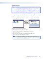
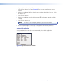
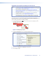
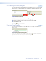
5. When loading a clip — The LCD displays the
second step of the Select a clip file screen (see figure 13). Proceed to step 6.
5
Figure 13. Select a Clip File Screen
6. Rotate the encoder knob as necessary to highlight the desired clip file.
7. Press the Enter button. The LCD returns to the Channel Status screen with the clip
selected in step 5 shown in the clip field. The Play/Pause button lights. The procedure is
complete.
Video selection
The LCD can show the control display, the video playback display, or both
simultaneously (an alpha blend). To fully display the video playback (without an
alpha blend), rotate the encoder knob to highlight the Video selection and press the Enter
button.
To return to the channel status display or alpha blend, press the Previous button.
Frame selection
In Frame mode, you can step frame-by-frame through the selected CPL or clip file while the player is playing video. To turn Frame mode on, rotate the encoder knob to
highlight the Frame selection and press the Enter button.
Rotate the encoder knob to the left or right to step forward or backwards through the clip
frame by frame.
NOTE:
This function is identical to selecting the front panel Frame mode button (
).
To return to the Channel status display, press the Previous button.
Shuttle selection
In Shuttle mode, you can “shuttle” backwards and forwards through the selected
playlist or clip file, at a rate controlled by the encoder knob. To turn Shuttle mode on,
rotate the encoder knob to highlight the Shuttle selection and press the Enter button.
Rotate the encoder knob to the left or right to fast forward or reverse through the clip at up
to 16 times regular playback speed. Use the encoder knob to return the shuttle indicator to
the middle (vertical) position to play the file at normal speed.
NOTES: • This function is identical to selecting the front panel Shuttle mode button (
).
• The audio portion of the clip is active only when the playback speed is +1.0
(normal forward speed).
To return to the Channel status display, press the Previous button.
JMP 9600 Media Player • Operation
19
Loop selection
In Loop mode, the player runs the selected playlist or clip file in a continuous loop,
automatically starting the presentation over again once it ends. To toggle Loop mode
on and off, rotate the encoder knob to highlight (box) the Loop selection and press the
Enter button.
Mute selection
To toggle audio mute on and off, rotate the encoder knob to highlight (box) the
Mute selection and press the Enter button. Mute disables the audio output from all 16
audio channels when the media player is in 1-channel mode. Mute disables audio
channels 1 through 8 for video channel 1 and audio channels 9 through 16 for video
channel 2 when the media player is in 2-channel or 2-channel locked mode.
NOTE:
Audio is unmuted (is output) when power is cycled.
Settings menu
The Settings menu (see figure 14) provides submenus to control the behavior of the player
and how it interacts with the connected audio/video systems and the network. Rotate the
encoder knob to highlight the desired submenu and press the Enter button.
Figure 14. Settings Menu
NOTE:
Figure 14 is not an accurate image of the Settings menu. The figure is
elongated to show all selections in the menu. On the media player, the Video
selection is not visible until you rotate the Encoder knob to scroll down the
menu.
To return to the Settings menu from any of its submenus, press the Previous button.
JMP 9600 Media Player • Operation
20
Audio submenu
The Audio submenu (see figure 15) provides controls to set the volume and audio delay
variables for the one or two output groups.
Media player set to 2-channel or
2-channel locked output
Media player set to 1-channel output
Figure 15. Audio Submenu
NOTE:
The image shown on the left in figure 15 shows the audio menu when the
media player is set to either 2-channel or 2-channel locked output. The
submenu on the right is 1-channel locked output. Use the Settings > Video
submenu to select the mode.
Adjust the values as follows:
1. Rotate the encoder knob to highlight the selected variable.
2. Press the Enter button.
3. Rotate the encoder knob to change the selected variable to the desired value.
4. Press the Enter button to enter the variable and “jump” the selection highlight to the
next variable.
JMP 9600 Media Player • Operation
21
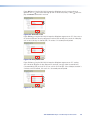
Autostart submenu
NOTES: • The player must be correctly configured for the clip or playlist that you select
using the Settings > Video submenu, or else the player does not load the
selected clip or playlist and the LCD reports ERROR.
• If you cannot get a clip to load, see “Setting the clip or playlist to
autoplay and view clip info“ in the “HTML Operation” section to view the
properties of the clip, which can help reveal the problem.
The Autostart feature sets a specified clip or playlist to automatically start playing for
channel 1 or channel 2 whenever the media player powers up and has loaded its operating
system. The Autostart submenu provides controls to select a clip or playlist and enable or
disable autostart. Enable an autostart as follows:
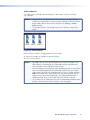
1. Rotate the encoder knob to highlight the channel (1 or 2) that you want to autostart
(see figure 16).
2
ENTER
1
3
5
Figure 16. Autostart Submenu Flowchart
2. Press the Enter button. The enable screen appears.
3. Rotate the encoder to highlight the Enable Autostart check box.
4. Press the Enter button.
5. Rotate the encoder to highlight either Playlist or Clip radio button.
6. Press the Enter button. The radio button is selected.
NOTE:
If a clip or playlist is displayed in the field beneath the radio buttons and
you are satisfied with it, the process is complete. Press the Previous button
twice to return to the Settings submenu.
JMP 9600 Media Player • Operation
22
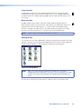
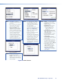
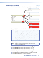
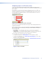
7. To select or change the clip or playlist that is displayed in the field beneath the radio
buttons, rotate the encoder button to highlight the field (see figure 17).
8
10
9
ENTER
ENTER
7
9
Figure 17. Select a Clip File Screen
8. Press the Enter button. The field displays a list of available playlists or clips, depending
on the selection made in step 5.
9. Rotate the encoder knob as necessary to highlight the desired playlist or clip file.
10.Press the Enter button. The field displays the selected playlist or clip file.
11.Press the Previous button twice to return to the Settings submenu.
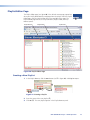
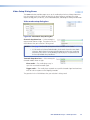
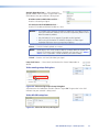
Date and Time submenu
The Date and Time submenu provides a tool to change the real time clock set in the media
player (see figure 18).
Figure 18. Date and Time Submenu
NOTE:
The media player does not automatically support Daylight Saving Time. Use
this submenu to account for Daylight Saving Time if desired.
JMP 9600 Media Player • Operation
23
Adjust the date and time as follows:
1. Rotate the encoder knob to highlight the first variable to be changed.
NOTE:
Rotating the encoder knob selects through the variables in the following
order: Month > Day > Year > Hour > Minute > Second >Month ... .
2. Press the Enter button.
3. Rotate the encoder to change the selected variable to the desired value.
4. Press the Enter button. The highlight jumps to the next variable.
5. Repeat steps 1 through 4 as necessary to change all variables.
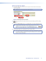
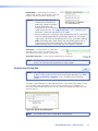
6. Press the Preview button to exit the most recently changed value. The player prompts
you to see if you really want to change the value (see figure 19).
Figure 19. Apply new settings? Prompt
7. Rotate the encoder as necessary to highlight either Yes or No.
NOTE:
If you do not perform steps 7 and 8, the player abandons the changes and
displays the Settings menu after approximately 30 minutes.
8. Press the Enter button. The screen displays the Settings menu.
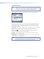
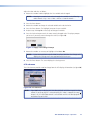
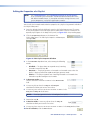
LCD submenu
The LCD submenu provides a tool to change how the LCD displays information (see figure 20).
Figure 20. LCD Submenu
NOTE:Figure 20 shows the display with the video playback overlaid on top of the GUI
control. If no clip or playlist is selected to play or if video is stopped (the stop [ ]
button is lit), the GUI/Video control is not available and the no video playback is
overlaid on top of the GUI.
JMP 9600 Media Player • Operation
24
Slider-type controls — The GUI/Video control adjusts the mix of the video image and the
graphical user interface (the “alpha blend”). The Brightness and Contrast controls function
the same as similar controls on any video monitor. Adjust the display controls as follows:
1. Rotate the encoder to highlight the desired variable.
2. Press the Enter button.
3. Rotate the Encoder knob to adjust the setting:
GUI/Video — All the way to the left displays 100% of the GUI control. All the way to
the right displays 100% of the video image.
Brightness — Left (0) is darker, right (100) is brighter. The default setting is 0.
Contrast — Left (0) is maximum contrast, right (100) is minimum contrast. The default
setting is 30.
NOTE:The adjustments take effect as you make them in step 3.
4. Press the Enter button to confirm the setting and continue to the next parameter.
—or—
Press the Previous button to confirm the setting and return to the previous menu.
Button-type controls — The Turn OFF LCD backlight control turns the LCD off. This can
be helpful to reduce distraction when the player is in the same room as the presentation.
The Factory Settings control returns the LCD settings to their factory defaults. Operate
these controls as follows:
1. Rotate the encoder to highlight the desired control.
2. Press the Enter button.
NOTE:Turn the LCD back on by pressing either the Enter, Previous,
Frame mode ( ), or Shuttle mode ( ) button or by cycling power.
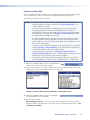
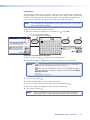
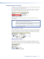
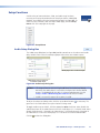
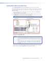
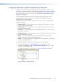
Networking submenu
The Networking submenu (see figure 21) provides tools to set up the media player for
use in a LAN. Use this submenu to access and change all of the port settings for both
Ethernet connections of the media player (see “Network parameters” and figure 22,
on the next page) and to ping another device on the network (see “Ping function“ and
figure 23, on page 28).
Figure 21. Networking Submenu
NOTE:
Two LAN ports allow the media player to reside on two different subnets
simultaneously.
JMP 9600 Media Player • Operation
25
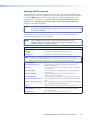
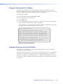
Network parameters —
The IP field contains the IP address of one the two the media player ports.
The Netmask field is used to determine whether the media player is on the same subnet
as the controlling PC when you are subnetting (see “Subnetting — A Primer“ for more
information).
The Gateway IP Address field identifies the address if you choose to use the media player
as a gateway to another device that is not on the same subnet.
Valid addresses for all fields above consist of four 1-, 2-, or 3-digit numeric subfields,
properly called octets, separated by dots (periods). Each field can be numbered from 000
through 255. Leading zeroes, up to 3 digits total per field, are optional.
The Enable DHCP check box directs the media player to obtain its IP address from a Dynamic
Host Configuration Protocol (DHCP) server (if the network is DHCP capable). Contact the
local system administrator to determine whether to use DHCP.
NOTES: • The factory default IP, netmask, and gateway addresses are as follows:
LAN (Network Interface) 1:
IP address: 192.168.254.254
Netmask address: 255.255.0.0
LAN (Network Interface) 2:
IP address: 192.168.254.253
Netmask address: 255.255.0.0
Both ports:
Gateway address: 0.0.0.0
DHCP: Off
• If these values conflict with other equipment at your installation, you can
change the addresses to any valid value.
• Editing the settings for an Ethernet port on which you have an active
connection can immediately disconnect the media player from the network
• If DHCP is enabled, the IP address and Netmask settings are disabled but can
be viewed from the front panel. Disable DHCP to change the IP address and
Netmask settings.
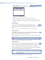
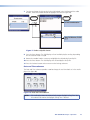
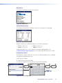
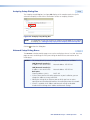
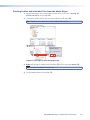
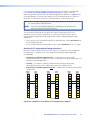
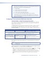
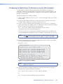
Edit any of the network parameter settings as follows (see figure 22):
2
1
ENTER
5
6
5
6
8
ENTER
7
4
3
5
6
Figure 22. Networking Submenu and Network Parameters Settings
JMP 9600 Media Player • Operation
26
1. Rotate the encoder to highlight the selection for the value or setting to be change (a on
figure 22 on the preceding page):
IP address — Interface 1 or 2, as applicable
Netmask 1 or 2 — Interface 1 or 2, as applicable
DHCP — Interface 1 or 2, as applicable
Gateway — Gateway
2. Press the Enter button (b).
NOTES: • If DHCP is enabled, the IP address and Netmask settings are disabled.
Disable DHCP (steps 1, 2, 5, and 6) to change the IP address and Netmask
settings.
• For a Gateway address, proceed to step 3.
• For DHCP, skip to step 5.
• For IP addresses and Netmask addresses, skip to step 9.
3. For a Gateway address, Rotate the encoder as necessary to select the LAN port
(Interface 1 or Interface 2) to use as a gateway (c).
4. For a Gateway address, press the Enter button. The Apply control appears in the
LCD. Proceed to step 9.
5. To toggle DHCP on or off, rotate the encoder as necessary to highlight the Enable
DHCP selection (d).
6. To toggle DHCP on and off, press the Enter button. The Apply control appears in the
LCD.
7. If you enabled DHCP or you do not want to manually set the addresses, proceed to
step 15.
8. To manually set addresses after disabling DHCP, proceed to step 9.
9. Rotate the encoder to highlight the first or next octet that needs to be changed (e).
10.Press the Enter button.
11.Rotate the encoder to change the selected octet to the desired value (f).
12.Press the Enter button. The highlight jumps to the next octet.
13.Repeat steps 9 through 12 as necessary to change all octets.
14.Press the Enter button.
15.Rotate the encoder as necessary to highlight the Apply control (g).
16.Press the Enter button (h).
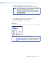
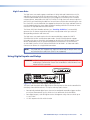
JMP 9600 Media Player • Operation
27
Ping function —
Use the Ping function to ‘ping’ another device on the network as follows:
1. Rotate the encoder to highlight the Ping IP selection (see a on figure 23).
2
6
3
ENTER
1
4
ENTER
5
Figure 23. Ping Function
2. Press the Enter button (b).
3. Rotate the encoder to highlight the first or next octet that needs to be changed (c).
4. Press the Enter button.
5. Rotate the encoder to change the selected octet to the desired value (d).
6. Press the Enter button. The highlight jumps to the next octet.
7. Repeat steps 3 through 6 as necessary to change all octets.
8. Press the Enter button.
9. Rotate the encoder as necessary to highlight the Ping control (e).
10.Press the Enter button (f).
Player submenu
The Player submenu provides a tool to give the player a unique name and location
(see figure 24).
2
3
5
4
ENTER
PREV
1
Figure 24. Player Submenu and Keyboard
Customize the player as follows:
1. Rotate the encoder to highlight the identifier, either Name or Location (see a figure 24).
2. Press the Enter button (b). An alphanumeric keyboard screen appears.
3. Rotate the encoder to highlight the first or next character in the identifier (c).
NOTES: •
is the back space key. Pressing Enter when this key is highlighted,
erases the character to the left of the cursor.
•
is the Caps key. Pressing Enter when this key is highlighted, toggles
the keyboard between uppercase and lowercase characters.
•
is the space key.
JMP 9600 Media Player • Operation
28
4. Press the Enter button (d).
5. Repeat steps 3 and 4 until the name or location is spelled out.
6. Press the Previous button to save the value and return to the Player submenu (e).
7. As desired, repeat steps 1 through 6 for the other identifier.
Reboot submenu
The Reboot submenu (see figure 25) provides a prompt that allows you to reboot the media
player without powering it down. Reboot the player as follows:
Figure 25. Reboot? Prompt
1. Rotate the encoder as necessary to highlight Yes. (Highlight No to abandon the reboot.)
2. Press the Enter button. The media player reboots.
Serial Ports submenu
The Serial Ports submenu provides a tool to configure serial port Remote 1
(see figure 26, below).
NOTES: • Serial port Remote 1 can be set to ControlMSVPP (control the player),
Passthrough (pass the signals through the player to and from a controlled
device), or Disabled.
• When you are using the Pass Through setting, ensure that the Baud
Rate, Parity, Data Bits and Stop Bit are set to match the device that you are
controlling. Also, in your remote control program, set the IP port number to
4001 and the IP address to that of media player. When the port is in Pass
Through mode, any TCP/IP control string that appears on port 4001 of the
JMP 9600 is passed to the Remote 1 port and any strings on the port pass to
port 4001.
• The media player can:
•• Operate at 300, 600, 1200, 1800, 2400, 4800, 9600, 19200, 38400,
57600, or 115200 baud rates
•• Use 7 or 8 data bits
•• Use no parity, even parity, or odd parity.
•• Use 1 or 2 stop bits
• Serial port Remote 2 is for factory use only. The customer or end user cannot
control the player via the Remote 2 port.
1
ENTER
4
2
3
ENTER
Figure 26. Serial Ports Submenu
JMP 9600 Media Player • Operation
29
Configure serial port Remote 1 as follows:
1. Press the Enter button (see a on figure 26). The Com port 1 configuration screen
appears.
2. Rotate the encoder to highlight the value to be set: Mode, Baud Rate, Data Bits, Parity,
or Stop Bits (b).
3. Press the Enter button.
4. Rotate the encoder to select the desired setting (c). See the note above for available
settings.
5. Press the Enter button (d).
NOTE:
The values are not changed if you do not press the Enter button.
6. Repeat steps 2 through 5 as necessary to change other configurable parameters.
System Info selection
View a snapshot of the status of the connections and settings of the media player
(see figure 27). Rotate the encoder to scroll to hidden parts of the display.
Figure 27. System Information Screen
JMP 9600 Media Player • Operation
30
Video submenu
The Video submenu provides tools to manage the video output settings and timing
(see figure 28).
NOTES: • Analog Channel 2 is displayed in the Video submenu (see figure 28) and
available for selection only in 2-channel output mode and 2-channel locked
output mode, both of which can be selected in the Settings > Video >
Mode selection.
• The Analog Channel 1 and Analog Channel 2 are identical, except where
noted.
Figure 28. Video Submenu
Make selections as follows (see figure 29, on the next page):
1. Rotate the encoder to highlight the desired selection.
2. Press the Enter button.
NOTES: • Figure 29 shows all of the possible options on the screens available in the
video submenu. Depending on the video mode and the enabled licenses,
some selections are not available on some screens.
• You can configure the media player signal combinations that are not defined
within the video payload identifier specification (SMPTE 352); for example
single channel, dual link HD-SDI operation with 12-bit 4:2:2 color sampling
and the RGB color space. Some displays may not correctly display such an
image or may require manual adjustment. The video payload identifier is
updated correctly when the next valid SMPTE 352 format is selected.
• The selections on the following screens act like Microsoft® Windows® radio
buttons; selecting one deselects the others in the same group.
JMP 9600 Media Player • Operation
31
HDSDI Selection
Mode Selection
NOTES: • See page 3 for detailed
descriptions of the functions of
the modes.
• The loop selections are independent of each other; you can
select one, both, or neither.
• Ch. 2 loop enabled is only
available for selection when the
switcher is in either 2-channel
mode or 2-channel-locked mode.
• In 2-channel or 2-channel locked
mode, the channels share the
same clock reference. Both
channels operate at the same
resolution and frame rate, which
is set by the loaded clip or
playlist. The parameters of the
last clip loaded take precedence.
GenLock Selection
NOTES: • The High Framerate, available on
the JMP 9600 2K model only,
supports resolutions of up to
1920x1080 and 2048x1080 at
48, 50, and 60 Hz.
The player must be set to
2-channel-locked mode to select
this rate. See “High Frame
Rate” in the “Detailed System
Interaction” section for more
details on this mode.
• When in 1-Channel mode and
playing 4:4:4 content,
all outputs are active (Channels 1
and 2). When in 1-Channel mode
and playing 4:2:2 content, only
Channel 1 outputs are active.
• The player ships with the
dual-link HD-SDI VPI tag on by
default. You may chose to turn it
off for backwards compatibility or
legacy support.
NOTES: • Master — Send both ESGEN and
MSGEN genlock as a master.
• ES Genlock — Receive ESGEN
genlock as a slave.
• MS9200 Genlock — Receive
MSGen genlock as a slave.
• Only JMP 9600 2K units
support ES genlock or
MS genlock.
• Black Burst PAL, Black Burst
NTSC, and Trilevel — Receive a
selected sync signal.
• Source indication — Indicates
the presence of an external
genlock signal.
• Lock indication —Indicates
synchronization with an external
genlock signal.
• The media player monitors the
sync inputs. If any selected sync
signal is lost, the media player
automatically defaults to Master.
• Media players with serial
numbers 9600-01 through
9600-50 support the Master,
ES Genlock, and MS9200
Genlock sync types only (see
“About menu” to identify the
serial number).
Timecode Selection
NOTES: • Chase — Stay in sync with a
received timecode signal.
• Trigger — Respond to a specific
Timecode and continue with no
further response to the ongoing
timecode signal.
Timecode Selection
Figure 29. Mode Selection
JMP 9600 Media Player • Operation
32
Lock menu
The Lock submenu allows the user to lock the front panel of the media player, limiting media
player operation by unauthorized personnel. When the player is locked, all of the front panel
functions are disabled except for the ability to unlock it. The player does not respond to an
other front panel operation. The lock is protected by a user-assigned password.
NOTE:
The media player can be controlled via MSVPP commands and the HTML pages
when the front panel is locked.
Toggle the front panel lock on and off as follows:
1. Rotate the encoder to highlight the text window (see a in figure 30).
— or — “locked” for unlock operation
— or — “unlocked” for lock operation
2
3
5
4
ENTER
7
PREV
ENTER
6
1
Figure 30. Lock and Unlock Operation
2. Press the Enter button (b). An alphanumeric keyboard opens.
3. Rotate the encoder to highlight the first or next character in the password (c).
NOTES: •
is the back space key. Pressing Enter when this key is highlighted,
causes erases the character to the left of the cursor.
•
is the Caps key. Pressing Enter when this key is highlighted, toggles
the keyboard between uppercase and lowercase characters. Passwords
ARE case sensitive.
•
is the space key.
4. Press the Enter button (d).
5. Repeat steps 3 and 4 until the password is spelled out.
6. Press the Previous button to return to the Lock or Unlock submenu (e).
7. Rotate the encoder to highlight the Lock or Unlock selection (f).
8. Press the Enter button (g).
NOTE:
If you are unlocking the front panel and if the password is incorrect, the
media player reports “Incorrect password!“ Repeat steps 1 through 8.
JMP 9600 Media Player • Operation
33
Help menu
View contact information for Extron (see figure 31).
Figure 31. Help Screen
System Status menu
View voltage and temperature information within the media player (see figure 32).
Figure 32. System Status Screen
Voltages should be in the following ranges to ensure optimum operation:
• 3.3 V: +3.2 to +3.4 V
•
5.0 V: +4.75 to +5.5 V
• 12.0 V: +12 to +13 V
•
–12.0 V: –12 to –13 V
Temperatures above 85 °C (185 °F) indicate an equipment cooling problem. See
“Troubleshooting a High Temperature“ in the “Mounting and Maintenance“ section.
License Keys menu
The License Keys submenu allows the user to enter an acquired product license, unlocking
the capabilities supported by that key.
Install a license as follows:
1. Obtain the license key from Extron.
2. Rotate the encoder to the first field in the key (see a in figure 33).
2
1
ENTER
3
5
4
7
PREV
ENTER
6
Figure 33. Licenses Operation
JMP 9600 Media Player • Operation
34
3. Press the Enter button (b). An alphanumeric keyboard opens.
4. Rotate the encoder to highlight the first or next character in the password (c).
NOTES: •
is the back space key. Pressing Enter when this key is highlighted,
causes erases the character to the left of the cursor.
•
is the Caps key. Pressing Enter when this key is highlighted, toggles
the keyboard between uppercase and lowercase characters. License
keys ARE case sensitive.
•
is the space key.
5. Press the Enter button (d).
6. Repeat steps 4 and 5 until the four characters of that license key field are spelled out.
7. Press the Previous button to return to the License Key submenu (e).
8. Repeat steps 2 through 7 for each field of the license key.
9. Rotate the encoder to highlight the Validate selection (f).
10.Press the Enter button (g).
About menu
View the serial number of the player and the revision levels of system elements (see figure 34).
Serial number nnnn
Figure 34. About Screen
NOTES: • The revision levels shown in figure 34 are examples only.
• The media player must run firmware version 2.06.07 or newer. If you have
an older version, update the firmware to ensure proper operation (see “Data
Transfer and Firmware Upgrade“ in the “Detailed System Interaction”
section).
JMP 9600 Media Player • Operation
35
Play a Presentation
Play a presentation as follows:
1. Rotate the encoder to highlight the Ch. 1 Status selection or Ch. 2. Status selection
(depending on which channel you want to output the video).
2. Press the Enter button. The selected Channel Status menu opens.
3. Select and load a playlist as described in “Playlist and Clip fields.”
) Button lights.
The Play/Pause (
NOTE:
If you load a new clip with a different resolution and frame rate than the
currently loaded clip, it can take up to 4 seconds before it is ready to play.
4. Press the Play/Pause (
) Button to start playing the file. The LCD screen displays a
progress-bar as the clip runs. The video output appears on the connected display system.
NOTE:
If you want the JMP 9600 LCD to fully display the video that is playing
(rather than a blend of the video and the control display), rotate the
encoder knob to highlight the Video Mode icon (
) and press the
Enter button.
Press the Previous button to return to the Channel Status menu or the
blended display.
JMP 9600 Media Player • Operation
36
HTML Operation
This section describes the operation of the JMP 9600 Media Player using its embedded HTML
pages, including:
• Opening the Embedded HTML Pages
• Player Control Page
• Playlist Editor Page
• Setup Functions
The player can be controlled and operated through either LAN port, connected via a LAN
or WAN, using a web browser such as Microsoft Internet Explorer. The display of the player
status or operation has the appearance of web pages. The following factory-installed
HTML pages and dialog boxes are available on the media player and cannot be erased or
overwritten.
• Player Control page — See figure 35, on the next page. Controls the transport,
similar to as on a VTR and also shows properties associated with specific clips and
playlists. This is the default startup page.
• Playlist Editor page — See figure 40, on page 43. Manages playlists and clip file,
manages clip-specific Timecode settings.
• Setup dialog boxes — Available from the Player Control page (see figure 47, on
page 47). A palette of dialog boxes that manages the player setup and configuration
and its interaction with the network system.
• MSVPP page — A stand-alone HTML page, not linked to the pages and the menu
of dialog boxes listed above, that provides an easy-to-use tool for entering MSVPP
commands. This page is described in the “Programming Guide” section (see “Opening
the embedded HTML MSVPP page” in that section).
NOTE:
If your Ethernet connection to the matrix player is unstable, try turning off the
proxy server in your web browser. In Internet Explorer, click Tools > Internet
Options > Connections > LAN Settings, uncheck the Use a proxy
server... box, and then click OK.
37
Opening the Embedded HTML Pages
Access the player using HTML pages as follows:
1. Start the web browser program.
2. Click in the Address field of the browser.
3. Enter the IP address of the connected port in the Address field of the browser.
NOTE: • If the local system administrators have not changed the value, the
factory-specified default IP addresses are as follows:
LAN 1:192.168.254.254 LAN 2:192.168.254.253
• To access the stand-alone MSVPP page, enter
<IP address>/msvpp.html, where “msvpp.html” is case sensitive.
4. Press the keyboard <Enter> key. The player downloads the Player Control page (see
figure 35) (or the MSVPP page if you accessed it as described in the NOTE above).
Player Control Page
The Player Control page (figure 37) is the default startup page, appearing when you initially
download the web pages from the player. If you are on the Playlist Editor page
(see figure 40), click the Player Control link at the top right of the page.
The Player control page consists of the Channel Control panel (transport
controls) and the Media Browser panel.
Channel Control
Media Browser
Figure 35. Player Control Page
The Player Control page continually updates itself to display the latest status of the clip or
playlist that is loaded.
JMP 9600 Media Player • HTML Operation
38
Channel 1 and 2 Control and Status Windows
The Channel Control panel portion of the Player Control page consists of one or two control
and status windows that display information unique to the output channels.
NOTES: • The Channel 2 control and status window is displayed only in 2-channel
output mode and 2-channel locked output mode, both of which can be
selected from the HTML Setup > Video > Mode dialog box submenu.
• The Channel 1 Status and Channel 2 Status are identical, except where noted.
Each channel window displays the real-time status information for the current content in the
upper half of the window and transport controls in the lower half of the window.
Real time status display
Figure 36. Real Time Status Display
Timecode — The Timecode counter shows the current point in
time within the loaded program. The Timecode counter includes the pre-roll, roll, and postroll periods.
Frame — The Frame counter shows the current point in time within
the currently loaded playlist or clip; the roll period only. The Frame counter runs in sync with
the Timecode counter but when paused, the actual frame is displayed.
Duration — The Duration display shows the entire run-time of the
currently loaded playlist or clip. This is a static display only.
NOTE
The frame field of the Timecode and Frame counters is not updated during
playback; only the hour:min:sec fields are active. The Timecode and Frame
counters show the frame number when paused, in Frame mode, or in shuttle
mode.
Playlist — The Playlist field shows the name of the currently loaded
playlist. If this field is empty, no playlist is loaded.
Clip — The Clip field shows the name of the currently
loaded clip. If this field is empty, no playlist is loaded.
Clip Info — The Clip Info field
describes the currently loaded clip, whether it is a stand-along clip or part of a playlist.
JMP 9600 Media Player • HTML Operation
39
Transport controls
Figure 37. Transport Controls
TIP: Rest the mouse over a control to see a pop-up tool tip that identifies the control, as
shown by the
pop-up in figure 37.
Progress bar — This bar tracks the
progress of a clip in play. If the clip is
paused, the progress bar freezes; if the clip is stopped the progress bar goes blank.
Shuttle control — Drag the pointer in this control to “shuttle” backwards and forwards through the playlist or clip file, at a rate
controlled and indicated by the pointer.
• Drag the pointer to the right to play forward in increments of 1x (normal speed — this
is the position shown at right), 2x, 4x, 8x and 16x normal speed.
• Drag the pointer to the left to play in reverse increments of -1x (normal speed but in
reverse), -2x, -4x, -8x and -16x normal speed.
NOTE:
The audio portion of the clip is active only when the playback speed is +1.0
(normal forward speed).
A tool tip displays at the top of the Player Control Page whenever you drag
the pointer away from its default (Play) position. You can also Pause the
presentation by dragging the pointer one stop to the left from the default position.
Previous clip ( ) control — Click this control to load the previous clip file in the playlist.
The control has no function if no playlist is loaded (see “Loading a Clip or Playlist into a
Player Channel”).
Stop ( ) control — Click this control to stop the currently playing presentation. When you
click the Play control, the presentation starts over from the beginning.
Pause ( ) control — Click this control to pause a currently playing presentation while
leaving the image displayed.
Play ( ) control — Click this control to start the currently selected playlist or clip file.
Next ( ) clip control — Click this control to load the next clip file in the playlist. The
control has no function if no playlist is loaded (see “Loading a Clip or Playlist into a
Player Channel”).
Jog control — When a channel is paused, click in the Jog control to
step forward or backward through the content, frame by frame.
Increments are ± 1, 5, 10 and 20 frames.
JMP 9600 Media Player • HTML Operation
40
Loading a Clip or Playlist into a Player Channel
NOTES: • You must have created one or more playlists before any are available for
selection to select (see “Playlist Editor Page“).
• Ensure that the media player is configured for 1-channel output before
attempting to load 4:4:4 chroma subsamped or stereoscopic content. If the
player is configured for 2-channel output mode and 2-channel locked output
mode, these formats will not load. Use the Setup > Video > Mode dialog
box submenu to check the video mode and change it if necessary.
• In 2-channel locked output mode, the files for the two channels must have
the same number of frames, resolution, bit depth, and number of audio
channel and must use 4:2:2 chroma subsampling. If these conditions are not
met, the files will not load.
• The player must be correctly configured for the clip or playlist that you select
using the Settings > Video submenu, or else the player does not load the
selected clip or playlist and the LCD reports ERROR.
• If you cannot get a clip to load, see “Setting the clip or playlist to
autoplay and view clip info“ to view the properties of the clip, which can
help reveal the problem).
• If you load a new clip with a different resolution and frame rate than the
currently loaded clip, it can take up to 4 seconds before it is ready to play.
1. If necessary, click the Clips panel header (see Ä in figure 38) or Playlists panel footer (Å)
in the Media Browser panel to open either the clip browser or playlist browser.
1a
2b
2a
1b
Figure 38. Loading a Clip or Playlist
2. Scroll through the list of available content to the desired clip or playlist.
3. Drag (Ç) the desired clip or playlist from the Media Browser panel and drop it (É) into
the desired channel window in the Channel Control panel. A green check appears while
dragging the clip or playlist when it is of a format that can be loaded.
4. Click the Play control ( ) to start the show.
JMP 9600 Media Player • HTML Operation
41
Setting the clip or playlist to autoplay and view clip info
NOTE: • The player must be correctly configured for the clip or playlist that you select
using the Setup > Video > Mode dialog box submenu, or else the player
does not load the selected clip or playlist.
• If you cannot get a clip to load, See “Setting the clip or playlist to
autoplay and view clip info“ to view the properties of the clip, which can
help reveal the problem.
• This page lets you set a clip file to autoplay only. To view and clear an
autoplay selection, use the Autoplay Setup Dialog Box.
• If you load a new clip with a different resolution and frame rate than the
currently loaded clip, it can take up to 4 seconds before it is ready to play.
The autoplay feature sets a specified clip or playlist to automatically start playing for
channel 1 or channel 2 whenever the media player powers up and has loaded its operating
system. Enable a clip or playlist to autoplay as follows:
1. In the Media Browser panel, right-click the file that you want to autoplay (see a in
figure 39). A dialog box appears.
1
2
3
4
Figure 39. Loading a Clip or Playlist
2. Click Set as Autoplay (b). The Set Autoplay dialog box appears.
NOTE:
Alternatively, you can click View Clip Info to open a dialog box that
shows details of the file, including:
• The file name
• The issuer (creator)
• The issue (creation) date
• The bit rate
• The resolution and frame rate
• The color depth
• The chroma subsampling rate
• The number of audio channels
• The audio width
Click the
to close the View Clip Info dialog box.
3. Select either the Channel 1 or Channel 2 check box (c).
4. Click the Ok button (d).
JMP 9600 Media Player • HTML Operation
42
Playlist Editor Page
The Playlist Editor page (see figure 40) is the default startup page, appearing
when you initially download the web pages from the player. From the Playlist
Editor page, click the Playlist Editor link at the top right of the page. The
Player control page consists the Playlist Browser, Playlist Editor, and Clip
Browser panels.
Playlist Browser
Playlist Editor
Clip Browser
Figure 40. Playlist Editor Page
Creating a New Playlist
1. In the Playlist Browser, click the New button (see a in figure 41). A dialog box opens.
2
3
1
Figure 41. Creating a Playlist
2. Enter the name of the new playlist (b).
3. Click OK (c). The new playlist appears in the Playlist Browser panel.
JMP 9600 Media Player • HTML Operation
43
Editing the Contents of a Playlist
To perform all of the playlist editing functions described in the various procedures below, you
must open the playlist in the Playlist Editor panel.
Open the desired playlist by clicking its name in the Playlist Browser panel. The name of the
playlist appears in the Edit Playlist panel header and the clip files included in the opened
playlist appear in the body of the panel (see figure 42).
Figure 42. Opening a Playlist
Once a playlist is open in the Playlist Editor panel, you can edit the playlist in the ways
described below.
NOTES: • Valid playlists must contain clip files that are all of the same resolution, color
space, frame rate, and number of audio channels.
Although you can create an playlist with DCPs of different formats, any such
playlist is invalid; you will receive an error message when you load the playlist
on the Player Control Page and the playlist will not play.
• After you add a clip to a playlist, you need to load or reload the playlist before
you can access or play the clip.
Add DCP (clip files) to a playlist
Drag and drop one or more files the from the Clip Browser panel to the Playlist Editor panel.
While you are dragging a file and before you drop it into the Playlist Editor panel, a dotted
bar appears in the panel to show where in the playlist the clip will appear (see figure 43).
Figure 43. Adding Clips to a Playlist
Reorder clip files in a playlist
Click and drag files within the Playlist Editor panel to reorder them. Before you release the
mouse button, a blue box shows where the in the playlist order the clip cam from and a
dotted line in the panel shows where in the playlist order the clip will appear (see figure 44).
Figure 44. Adding Clips to a Playlist
JMP 9600 Media Player • HTML Operation
44
Remove a clip file from a playlist
1. In the Playlist Editor panel, left-click the file that you want to remove from the playlist
(see a in figure 45).
TIP: Hold down the <Ctrl> key to select multiple clip files.
2
4
1
3
Figure 45. Removing Clips from a Playlist
2. Right-click anywhere over the clip files listed in the Playlist Editor panel (b). A dialog
box appears.
3. Left-click the Remove Clip button in the dialog box (c). A Message dialog box appears.
TIP: Or, preferred for multiple clips, select the files that you want to remove in
accordance with step 1 and then click the Remove button on the
footer of the Playlist Editor panel. The Message dialog box appears.
4. Left-click Yes to delete the selected clip files from the playlist (d).
TIP: When working extensively with playlists, try opening a second browser window.
This allows one browser to display the Player Control page and the second to
display the Playlist Editor page.
JMP 9600 Media Player • HTML Operation
45
Editing the Properties of a Playlist
NOTE:
See “Synchronization“ and “Configuring a player as an LTC master“
in the “Detailed System Interaction” section for a detailed discussion of the
JMP 9600 timecode feature, its interaction with other timing references and
system components, and specific application examples.
You can edit the timecode mode and other properties of a playlist using controls available in
the Playlist Editor panel.
1. Open the desired playlist by clicking its name in the Playlist Browser panel. The name
of the panel appears in the Edit Playlist panel header and the clip files included in the
opened playlist appear in the body of the panel (see figure 45 on the preceding page).
2. Click the Properties button on the footer of the
Playlist Editor panel. The Edit Playlist Properties window opens
(see figure 46).
Figure 46. Edit Playlist Properties Window
3. In the Timecode drop-down box, select among the following
modes:
• Disabled — The player does not respond to any incoming
timecode. Proceed to step 10.
• Generate — The player generates a timecode as a timecode master when the
playlist is playing. Proceed to step 4 to configure generate mode.
• Receive — The player responds to an incoming timecode as a timecode slave.
Proceed to step 8 to configure receive mode.
4. In Generate mode, enter
<hours:minutes:seconds:frames> in the Start Time
field.
5. If necessary, clip to select the Play at and Stop at
check boxes to allow you to enter time values.
6. If necessary, enter <hours:minutes:seconds:frames> in the
Play at and Stop at check boxes.
NOTE:
The display goes black when the Stop at time expires.
7. Proceed to step 10.
8. In Receive mode, if necessary, clip to select the Play at
check box to allow you to enter time values.
9. If necessary, Enter <hours:minutes:seconds:frames> in the Play at check box.
10.For all selections, click the Save button.
JMP 9600 Media Player • HTML Operation
46
Setup Functions
A wide variety of communications, video, and audio setup functions,
necessary to ensure peak performance of the player and the video/audio
playback, are available using the Setup palette of tools (see figure 47). To
select the setup functions, from the Playlist Editor page, click the Setup
Editor link at the top right of the page.
Figure 47. Setup Palette
Audio Setup Dialog Box
The Audio setup dialog box (see figure 48) provides controls to set the volume and audio
delay variables for the one or two output groups and to mute one or both outputs.
Media player set to 1-channel output
Media player set to 2-channel or
2-channel locked output
Figure 48. Audio Setup Dialog Box
NOTES: • The image shown on the left in figure 48 shows the audio setup dialog
box when the media player is set to either 2-channel or 2-channel locked
output. The dialog box on the right is 1-channel locked output. Use the
Setup > Video > Mode dialog box submenu to select the mode.
• Audio is unmuted (is output) when power is cycled.
To adjust the volume and delay values, click the up or down buttons ( ) as necessary. The
green bar in the field indicates that your selection is being saved.
To toggle audio mute on and off, click the appropriate Mute check box. Mute disables the
audio output from all 16 audio channels when the media player is in 1-channel mode. Mute
disables audio channels 1 through 8 for video channel 1 and audio channels 9 through 16
for video channel 2 when the media player is in 2-channel or 2-channel locked mode.
Click the
to close the dialog box.
JMP 9600 Media Player • HTML Operation
47
Autoplay Setup Dialog Box
The Autoplay setup dialog box (see figure 49) displays of the complete path of a clip file
selected to autoplay in each channel and buttons to clear an autoplay selection.
Figure 49. Autoplay Setup Dialog Box
NOTE:
Click the
This dialog box lets you view and clear an autoplay selection only. To set a clip file
to autoplay, see “Setting the clip or playlist to autoplay and view clip info“.
to close the dialog box.
Network Setup Dialog Boxes
The Network selection provides pages to set up the media player for use in a LAN. Use these
pages to access and change all of the port settings for both Ethernet connections of the
media player.
NOTES: • The factory default IP, netmask, and gateway addresses are as follows:
LAN (Network Interface) 1:
IP address: 192.168.254.254
Netmask address: 255.255.0.0
LAN (Network Interface) 2:
IP address: 192.168.254.253
Netmask address: 255.255.0.0
Both ports:
Gateway address: 0.0.0.0
DHCP: Off
• If these values conflict with other equipment at your installation, you can
change the addresses to any valid value.
• Editing the settings for an Ethernet port on which you have an active
connection can immediately disconnect the media player from the network
• If DHCP is enabled, the IP address and Netmask settings are disabled.
Disable DHCP to change the IP address and Netmask settings.
JMP 9600 Media Player • HTML Operation
48
Network Ethernet setup dialog boxes
1. Select Network > Ethernet 1 or Network > Ethernet 2 to
open the selected Ethernet setup dialog box (see figure 50).
Figure 50. Ethernet Setup Dialog Box
2. For the IP Address and Netmask (subnet mask) fields:
a. Click in the desired field.
b. Edit the address as desired.
3. Click the Mode drop-down box and select either
Static or DHCP.
4. Click the Save button.
5. Click the
to close the dialog box.
Network Gateway setup dialog box
1. Select Network > Gateway to open the Gateway dialog box
(see figure 51).
Figure 51. Gateway Setup Dialog Box
2. Click the Mode drop-down box and select
either eth0 or eth1.
NOTE:
eth0 = LAN port 1.
eth1 = LAN port 2.
3. Edit the address as desired.
4. Click the Save button.
5. Click the
to close the dialog box.
JMP 9600 Media Player • HTML Operation
49
License Management Setup Dialog Box
The License Management setup dialog box (see figure 52) allows the user to see the installed
license and enter an acquired product license, unlocking the capabilities supported by that
key.
2
3
1
Figure 52. Enter a License Key
1. Obtain the license key from Extron.
2. Click the Install New License button (see a in figure 52).
3. Enter the 32 characters of the new license into the license key field (b).
4. Click the OK button (c).
5. Click the
to close the dialog box.
Player Info Setup Dialog Box
The Player Info setup dialog box (see figure 53) allows the user to give the media player a
distinct identity.
Figure 53. Player Info Setup Dialog Box
Enter a name and location in the appropriate fields. Click the to close the dialog box. The
green bar in the field indicates that your selection is being saved.
JMP 9600 Media Player • HTML Operation
50
Serial Port Setup Dialog Box
The Serial Port setup dialog box provides tools to configure serial port Remote 1 (see figure 54).
1
7
1
2
3
6
4
5
Figure 54. Serial Port Setup Dialog Box Submenu
NOTES: • Serial port Remote 1 can be set to disabled, controlmsvpp (control the
player), or passthrough (pass the signals through the player to a controlled
device).
• When you are using the passthrough mode, ensure that the Baud Rate,
Data Bits, Stop Bits, and Parity are set to match the device that you
are controlling. Also, in your remote control program, set the IP port number
to 4001 and the IP address to that of media player. When the port is in
passthrough mode, any TCP/IP control string that appears on port 4001 of
the JMP 9600 is passed to the Remote 1 port.
• Serial port Remote 2 is for factory use only. The customer or end user cannot
control the player via the Remote 2 port.
Configure serial port Remote 1 as follows:
NOTE:
You do not need to perform those steps that make changes that are
unnecessary for your configuration.
1. Click the Mode drop-down box and select among the settings (see a in figure 54).
2. Click the Baud Rate drop-down box and select among the settings (b).
3. Click the Data Bits drop-down box and select among the settings (c).
4. Click the Stop Bits drop-down box and select among the settings (d).
5. Click the Parity drop-down box and select among the settings (e).
6. Click the Save button or the Cancel button to save or abandon the changes (f).
7. Click the
or the Cancel button to close the dialog box (g).
JMP 9600 Media Player • HTML Operation
51
Video Setup Dialog Boxes
The Video selection provides pages to set up the media player for best video performance.
Use these pages to set the number of channels the player outputs, configure the video
outputs (analog, DVI-I, or HD-SDI), set the video colorspace, and configure video synchronization.
Video mode setup dialog box
Figure 55. Video Mode Setup Dialog Box
Channels drop-down box — Select among the
output modes shown at right. The green bar in the
field indicates that your selection is being saved.
NOTES: •See page 3 for detailed descriptions of the functions of the modes.
• In 2-channel or 2-channel locked mode, the channels share the same clock
reference. Both channels are constrained to operate at the same resolution
and frame rate, which is set by loading a clip or playlist. The parameters of
the last clip loaded take precedence.
Timecode drop-down box — Select among the
timecode modes shown at right.
Chase mode — The media player stays in
sync with a received timecode signal.
Trigger mode — The media player responds to a specific timecode signal and continues
with no further response to the ongoing timecode.
The green bar in the field indicates that your selection is being saved.
JMP 9600 Media Player • HTML Operation
52
Genlock drop-down box — Select among the
genlock modes shown at right. The green bar in the
field indicates that your selection is being saved.
Black Burst PAL and Black Burst NTSC —
Receive a selected sync signal.
ES Genlock and ES MS9200 Genlock —
Receive ES Genlock or MS9200 Genlock as a slave.
NOTES: • ES Genlock and ES MS9200 Genlock are proprietary sync signals that are
native to Electrosonic products that have been acquired by Extron and to
older Electrosonic products.
• Only JMP 9600 2K units support ES genlock and MS genlock.
• When using ES Genlock or ES MS9200 Genlock, the video signal
resolution and frame rate must match on all players.
Master — Send ES Genlock genlock as a master.
NOTE:
Media players with serial numbers 9600-01 through 9600-50 support the
Master, ES Genlock, and ES MS9200 Genlock sync types only (see “About
menu” in the “Operation” section to identify the serial number).
Trilevel — Receive a tri-level (HD video) sync signal.
Loop check boxes — Select (check) and deselect the channel loop modes as
desired.
Video analog setup dialog box
Figure 56. Video Analog Output Setup Dialog Box
Select between the Colorspace selections shown in figure 56. The green bar in the field
indicates that your selection is being saved.
Video HD-SDI setup box
Figure 57. Video HD-SDI Setup Dialog Box
JMP 9600 Media Player • HTML Operation
53
HDSDI Mode — Select between the output
modes shown at right. The green bar in the field
indicates that your selection is being saved.
*
*
*
NOTES: • The Dual Link High Framerate,
* These selections are available
available on the JMP 9600 2K
in 1 channel mode only.
model only, supports resolutions
of up to 1920x1080 and
2048x1080 at 48, 50, and 60 Hz. The player must be set to 2-channel-locked
mode to select this rate. See “High Frame Rate” in the “Detailed System
Interaction” section for more details on this mode.
• You can configure the media player signal combinations that are not defined
within the video payload identifier specification (SMPTE 352); for example
single channel, dual link HD-SDI operation with 12-bit, 4:2:2 color sampling
and the RGB color space. Some displays may not correctly display such an
image or may require manual adjustment. The video payload identifier is
updated correctly when the next valid SMPTE 352 format is selected.
Colorspace — Select between the Colorspace
selections shown at right. The green bar in the
field indicates that your selection is being saved.
VPI enable check box — Select (check) and deselect VPI as desired.
NOTE:
The player ships with the dual-link HD-SDI VPI tag on by default. You may chose
to turn it off for backwards compatibility or legacy support.
About Setup Dialog Box
NOTE:
The media player must run firmware version 2.06.07 or newer. If you have
an older version, update the firmware to ensure proper operation (see “Data
Transfer and Firmware Upgrade“ in the “Detailed System Interaction”
section).
The About setup dialog box (see figure 58) displays the exact media player model, revision
levels, and disk usage information. Firmware revision (to identify when upgrades are
necessary) and disk usage (to determine if there is room for loading more clip files) are of
particular interest.
Figure 58. About Setup Dialog Box
NOTE:
The revision levels shown in figure 58 are examples only.
JMP 9600 Media Player • HTML Operation
54
Programming
Guide
This section describes MSVPP command control of the JMP 9600 Media Player, including:
• Control Ports
• Host-to-Player instructions
• Using the Command and Response Table
Control Ports
The media player has three remote control ports make remote control of the player possible:
Remote port 1 — An RS-232 port on a 9-pin D female connector
LAN ports 1 and 2 — Local area network (LAN) port or wide area network (WAN) ports on
RJ-45 connectors
Remote Port 1
See item h and “Remote Control Port” on page 10.
NOTES: • The player can:
•• Operate at 300, 600, 1200, 1800, 2400, 4800, 9600, 19200, 38400,
57600, or 115200 baud rates
•• Use 7 or 8 data bits
•• Use no parity, even parity, or odd parity.
•• Use 1 or 2 stop bits
• If necessary, use the front panel controls to set the port to ControlMSVPP (see
“Serial Ports submenu” in the “Operation” section).
• Serial port Remote 2 is for factory use only. The customer or end user cannot
control the player via the Remote 2 port.
LAN Ports
The rear panel Ethernet connector on the media player can be connected to an Ethernet
LAN or WAN (see item g and “LAN Ports” on page 9). The simplest way to establish
communications between the player and the controlling device is via the built-in HTML
MSVPP page, although you can use other communication utilities. The MSVPP commands
and the actions of the player are identical to the commands and actions the player has when
communicating with it via its RS-232 port.
JMP 9600 Media Player • Programming Guide
55
Default IP Addresses
To access the media player via either LAN port, you need the IP address for the port that you
are using, and may need the netmask mask and the gateway address. The factory-specified
defaults are:
• IP address (port 1): 192.168.254.254
• Netmask mask:
255.255.0.0
• DHCP:
off
• IP address (port 2): 192.168.254.253
• Gateway address: 0.0.0.0
These values can be viewed and changed from the front panel (see “Networking
submenu“ in the “Operation“ section).
Opening the embedded HTML MSVPP page
The simplest way to establish communications between the player and the controlling device
is via the built-in HTML MSVPP page. Open the HTML MSVPP page as follows:
1. On your computer, start the web browser program such as Microsoft Internet Explorer.
2. Click in the Address field of the browser.
3. Enter enter <IP address of the connected port>/msvpp.html in the Address
field of the browser, where “msvpp.html” is case sensitive.
4. Press the keyboard <Enter> key. The player downloads the MSVPP page (see figure 59).
Figure 59. MSVPP Page
JMP 9600 Media Player • Programming Guide
56
5. Enter valid MSVPP commands (see “Command and Response Table for MSVPP
Commands“) in the Command field and press the keyboard <Enter> key. The media
player responds accordingly.
TIPS: • Previous commands are available using the drop-down list of the Command
field (click ).
• If you enter a folder or file name with the wrong case, such as CLip-1 rather
than Clip-1, refresh the page (click ) after you correct the error to ensure
that the original, incorrect, command is not substituted.
Host-to-Player Instructions
NOTE:
The format for the JMP 9600 Media Player is DIFFERENT than most other
Extron products. Read this section CAREFULLY.
Valid MSVPP commands consist of the following:
• A command word — Commands words are defined in the Command and Response
Table for MSVPP Commands. Commands are not case sensitive. Variables, such as file
names, are case sensitive.
• Zero, one, or more parameters (X`s) — Parameters are defined in “Symbol
Definitions,” on the next page. Multiple parameters must be separated by a space
character (•). Parameters that include spaces must be enclosed in double quotes (“).
• Terminator — A carriage return without a line feed (}) terminator is required to end a
command character sequence.
NOTE:
If you are connected via either LAN port and are using the MSVPP page,
pressing the keyboard <Enter> key at the end of the command provides a
valid terminator.
When a command is valid, the unit executes the command and sends a response to the
host device. All responses from the unit to the host end with a carriage return and a line
feed (CR/LF = ]), which signals the end of the response character string. When a command
involves both channels (X# = 1,2), the unit responds separately for each channel.
JMP 9600 Media Player • Programming Guide
57
Using the Command and Response Table
Symbols (parameters), defined below, are used throughout the Command and Response
Table for MSVPP Commands, which begins on page 60. The symbols represent variables
in the command/response table fields. Letters in the command field are not case-sensitive.
Hexadecimal equivalent are not necessary for the MSVPP command set, with the possible
exception of the carriage return character (0x0D) and the line return chararacter (0x0A).
Symbol Definitions
]
= CR/LF (carriage return/line feed)
}
•
X!
X@
X#
X$
= Carriage return (no line feed)
= Space (hard) character
Name of a DCP folder (such as “720p_422_60_donkey“)
Name of a clip file (such as “rafting_720p_5994.cpl.xml“)
= Folder name
= Clip name
= Output (channel)
1 = channel 1
= Playlist name
Name of a playlist file (such as “Canyon documentary.espl.xml”)
2 = channel 2
1,2 = both channels
NOTE: For the clip name (X@) and playlist name (X$), the name that you enter must include the file extension (“cpl.xml” for a clip or
“espl.xml” for a playlist) to be valid. If you try to enter a name without the file extension, the media player responds with ERROR.
X%
X^
= Playlist position
Sequential postion of a clip in a playlist
= Play speed
Speed at which to play video, where:
1.0 is normal speed, 2.0 is 2x normal speed, and so on
A positive value (+) is forward video (+ is assumed if no direction is specified)
A negative value (–) is reverse video
Fractional speeds are rounded up or down to the 3rd decimal place (0.000)
X&
= Frame count for advance command
Number of video frames to jump forward or backward, where:
A positive value (+) is forward (+ is assumed if no direction is specified)
A negative value (–) is reverse
X*
X(
= Frame count for seek and assorted timecode commands
nn:nn:nn:nn (“hour”:”minute”:”second”:”frame”)
= Property name
“PlayAt“, “StartTime“, “StopTime“, or “TimecodeMode”
NOTE: All names, file names, clip names, and property names, are case sensitive.
X1)
= Playlist property value
X1!
X1@
X1#
X1$
X1%
= Timecode mode
X1) = “Disabled“, “Generate“, or “Receive”
If X( = “TimecodeMode“:
If X( = “PlayAt“, “StartTime“,
X1) = nn:nn:nn:nn (hours:minutes:seconds:frame)
or “StopTime“:
X1) = the path to the playlist file (an empty character if the file is in the If X( = “Path“:
root playlist folder)
“timecodeGenerate“ or “timecodeReceive”
= Timecode receive mode setting
“chase“ or “trigger”
= On/off (audio mute, loop, input trigger)
0 = off or 1 = on
= Video mode
“1_channel”, “2_channel”, or “2_channel_locked”
= Video output
video.hdsdi = HD-SDI output video (channel 1 and channel 2)
ch1.video.dac = channel 1 analog video
ch1.video.dvi = channel 1 digital video
ch2.video.dac = channel 2 analog video
ch2.video.dvi = channel 2 digital video
“rgb” or “yprpb•bt.709”
X1^ =Colorspace
X1& = Color value
X1* = Alpha blend
X1( = Time
X2) = Genlock mode
NOTE:
000 (none) through 255 (maximum)
000 through 255
0.00 (seconds) though 255.0
“master“, “esgen“, “esgenlegacy“, “blackburst_ntsc“, “blackburst_pal“,
or“trisynch“
“esgen“ is sync slaved to the proprietary Electrosonic ESGen sync.
“esgen_legacy“ is sync slaved to the proprietary Electrosonic ESGen sync (native to older products, such as the MS9200).
“master“ is ESGEN sync output as a master.
“trisynch” is HDTV tri-level sync.
JMP 9600 Media Player • Programming Guide
58
X2!
X2@
= HD-SDI enable state
0 = not enabled, 1 = enabled
= HD-SDI mode
“single”, “dual_422_12”, “dual_444_10“, or “dual_444_12“ or
“dual_422_hfr“
NOTES: • The “dual_422_hfr” high frame rate is a licensed option of the JMP 9600 2K model.
• The high frame rate supports resolutions of up to 1920x1080 and 2048x1080 at 48, 50 and 60 Hz. High frame rate uses
the dual HD-SDI connection mode per SMPTE 372M. The player must be set for 2-channel-locked mode and only content
specifically encoded for the high frame rate mode plays back correctly.
X2#
X2$
X2%
X2^
X2&
= Delay
± up to 500 milliseconds
= Volume
0 (no attenuation, full volume) through –144 (full attenuation, audio
effectively muted)
= License key
32 alphanumeric digits
= License
Installed license (such as “V2HD“ or “V22K“)
= Serial port baud rate
300, 600, 1200, 1800, 2400, 4800, 9600, 19200, 38400, 57600, or
115200
= Parity
“none”, “even”, or “odd”
= Data bits
7 or 8
= Stop bits
1 or 2
= Serial port mode
X2*
X2(
X3)
X3!
X3@
X3#
X3$
X3%
X3^
X3&
X3*
= Ethernet port
“controlMSVPP“, “disabled“, or “passthrough”
“Eth0” or “Eth1” (for LAN port 1) or “Eth2” (for LAN port 2)
= IP address, Netmask, gateway address
###.###.###.###
= DHCP on/off status
“On“ or “Off”
= Hardware (MAC) address
##:##:##:##:##:##
= Digital Input port or Relay output port
1, 2, 3, or 4
= Level
“+“ = high level, logic 1; “–” = low Level, logic 0
= Date
In the format: MM/DD/YYYY where:MM = month: 01 (Jan) through 12 (Dec)
DD = day: 01 through 31
YYYY = year: 1970 through 2037
X3(
= Time
In the format: HH:MM:SS where:
X4)
= Identifier
HH = hour: 00 through 23
MM = minutes: 00 through 59
SS = seconds: 00 through 59
Location or name
NOTE: If there are spaces (•) In the identifier (such as Theater 1), the entire name must be enclosed in double quotation marks in the set
command (such as “Theater 1”). Quotes are not required for a single word identifer (such as Theater).
The identifier is always in quotes in the response.
X4! = Memory capacity or availablility
X4@ = Video mode / channel availability
X4# = Horizontal or vertical resolution
X4$ = Scan type
X4% = Frame rate
X4^ = Player state
X4& = Frame count
X4* = Percentage
X4( =Temperature
X5) = Voltage sensor
In 1024-byte blocks
1 (1-channel mode) or 2 (2-channel mode or 2-channel locked mode)
Horizontal: 1280, 1920, or 2048
Vertical: 780 or 1080
i (interlaced) or p (progressive)
23.98, 24, 24, 29.97, 30, 48, 50, 59.94, or 60
“playing“, “paused”, or “stopped”
Number of frames (total or current position)
Current position in a playing clip expressed as a percentage
nn.nn °C
“ps1•5vdc“
“ps1•3.3vdc“
“ps1•12vdc“
“ps1•–12vdc“
“ps2•5vdc“
“ps2•3.3vdc“
“ps2•12vdc“
“ps2•–12vdc“
NOTES: • The sensor name must be enclosed in double quotation marks as shown.
• Positive voltage sensor names must not include the positive sign (+); negative voltage sensor names must include the negative
sign (–).
X5! = Voltage
X5@ = Version
X5# =Date
±n.nn (3.3 vdc and 5 vdc sensors) or ±nn.nn (12 vdc sensors)
JMP 9600 Media Player • Programming Guide
59
Command and Response Table for MSVPP Commands
Command
MSVPP Command
Response
(host to unit)
(unit to host)
Additional description
Media management
View directory
GetMediaTree}
Example:
GetMediaTree}
GetClips•X!}
View clips
Example:
Load a clip
JMP 9600 Media Player • Programming Guide
Example:
GetMediaClips•720p_422_60_rafting}
LoadClip•X#•X!/X@}
List all DCP folders (clips and playlist) saved in the media
MediaBranch•1•X!]
player.
MediaBranch•1•X!]
•
•
•
•
MediaBranch•1•X!]
MediaBranch]
MediaBranch•1•720p_422_60_donkey]
MediaBranch•1•720p_422_60_rafting]
•
•
•
•
MediaBranch•1•9600_1200x720_48p_Canyon]
MediaBranch]
Clip•”X@”]
List all clips (*.cpl.xml files) within a folder (X!). If X! is
•
•
not a value returned by the GetMediaTree command,
•
•
no X@s are listed in the response.
Clip•”X@”]
Clip]
Clip•“rafting_720p_5994.cpl.xml”]
Clip]
OK]
LoadClip•1•720p_422_60_rafting/rafting_720p_5994.cpl.xml}
OK]
Load a clip to play. This command performs the same
function as the front panel load, see “Playlist and
Clip Files.“ The Play/Pause (
) button lights. If X!
and X@ are not values returned by the GetMediaTree
command and GetMediaClips command, or if the
media player is not correctly configured for the clip
that you select, the media player responds with ERROR.
Load the rafting clip from the rafting folder to play on
channel 1.
NOTES: • If the folder name (X!) and the clip name (X@) contain any spaces (•), the entire set of parameters must be enclosed in quotes (“X!/X@“), for example:
LoadClip•1•”720p_422_60_rafting/river•rafting.cpl.xml”].
• Ensure that the media player is configured for 1-channel output before attempting to load 4:4:4 chroma subsampled or stereoscopic content. If the player is configured for
2-channel output mode and 2-channel locked output mode, these formats will not load. Use the Get•VideoMode MSVPP command to check the video mode.
• In 2-channel locked output mode, the files for the two channels must have the same number of frames, resolution, bit depth, and number of audio channel and must use
4:2:2 chroma subsampling. If these conditions are not met, the files will not load.
• If you cannot get a clip to load, see “Setting the clip or playlist to autoplay and view clip info“ in the “HTML Operation” section to view the properties of the clip,
which can help reveal the problem.
• If you load a new clip with a different resolution and frame rate than the currently loaded clip, it can take up to 4 seconds before it is ready to play.
KEY:
60
X! = Folder name
X@ = Clip name
X# = Output
Name of a DCP folder (such as “720p_422_60_donkey“)
Name of a clip file (such as “rafting_720p_5994.cpl.xml“)
1 = channel 1
2 = channel 2
1,2 = both channels
Command/response table for MSVPP commands (continued)
Command
MSVPP Command
Response
(host to unit)
(unit to host)
Additional description
Media management (continued)
Load the next clip to
play
LoadNextClip•X#•X!/X@}
OK]
Load a clip to play automatically after the clip that is
currently playing in channel X# ends. If X! and X@ are
not values returned by the GetMediaTree command
and GetMediaClips command, or if the media player is
not correctly configured for the clip that you select, the
media player responds with ERROR.
NOTES: • If you send multiple LoadNextClip commands, each overwrites the one before it; only the most recently loaded clip is available to be played.
• If the folder name (X!) and the clip name (X@) contain any spaces (•), the entire set of parameters must be enclosed in quotes (“X!/X@“), for example:
LoadNextClip•1•”720p_422_60_rafting/river•rafting.cpl.xml}”.
Create a playlist
Example:
OK]
CreatePlaylist•X$}
CreatePlaylist•Canyon documentary.espl.xml}
OK]
Create a Canyon documentary playlist.
NOTE: Clips within a playlist must have the same resolution and frame rate.
Add a clip to a playlist
JMP 9600 Media Player • Programming Guide
Example:
AddPlaylistItem•X$•X!/X@•X%}
Add the clip file X@, in the folder X!, to playlist X$ at
position X%. The clip previously at position X%, and all
clips after it sequentially, slip by one position. If you
specify a position (X%) that is larger than the number
of clips in the playlist, the clip goes at the end. If the
playlist does not already exist, the media player creates
it automatically as it executes the command.
AddPlaylistItem•River activities.espl.xml•720p_422_60_kayak/kayak_720p_5994.cpl.xml•2}
Add a clip on kayaking to the playlist on river activities.
OK]
The kayaking clip plays second. Create the playlist
“River activities.espl.xml” if it does not exist.
OK]
NOTE: After you add a clip to a playlist, you need to load or reload the playlist before you can access or play the clip.
Move a clip in a playlist
Example:
KEY:
MovePlaylistItem•X$•X%current•X%new}
OK]
MovePlaylistItem•River activities.espl.xml•2•4}
OK]
X# = Output
X! = Folder name
X@ = Clip name
X$ = Playlist name
X% = Playlist position
1 = channel 1
2 = channel 2
1,2 = both channels
Name of a DCP folder (such as “720p_422_60_donkey“)
Name of a clip file (such as “rafting_720p_5994.cpl.xml“)
Name of a playlist file (such as “Canyon documentary.espl.xml”)
Sequential position of a clip in a playlist
Move the clip file in position X%current to position X%new.
Clips in between the two positions move up to fill the
empty space.
Move the clip in the second position in the river
activities the playlist to the fourth position.
61
Command/response table for MSVPP commands (continued)
Command
MSVPP Command
Response
(host to unit)
(unit to host)
Additional description
Media management (continued)
Append a clip to a
playlist
Example:
List clips in a playlist
AddPlaylist•X$•X!/X@}
Add the clip file X@, in the folder X!, to playlist X$. The
file cited in the command is added as the last clip in
the playlist. If the playlist does not already exist, the
media player creates it automatically as it executes the
command.
AddPlaylist•River•activities.espl.xml•720p_422_60_rafting/rafting_720p_5994.cpl.xml}
Add a clip on rafting to the end of a playlist on river
OK]
activities. Create the playlist “River activities.espl.xml” if
it does not exist.
List all of the clips in a playlist and the folders in which
ListPlaylist•X$}
PlaylistEntry•X$•X!/X@]
the clips are saved.
PlaylistEntry•X$•X!/X@]
OK]
•
•
Remove a clip from a
playlist
Example:
List playlists
RemovePlaylistItem•X$•X%}
•
•
PlaylistEntry•X$•X!/X@]
Playlist]
JMP 9600 Media Player • Programming Guide
OK]
RemovePlaylistItem•River•activities.espl.xml•2}
OK]
Playlist•X$]
ListAllPlayalists}
Playlist•X$]
Delete the clip at location 2 from the River activities
playlist
•
•
Load a playlist
Example:
KEY:
LoadPlaylist•X#•X$}
•
•
Playlist•X$]
Playlist]
OK]
Remove the clip at location X% from playlist X$.
LoadPlaylist•1•River•activities.espl.xml}
OK]
X! = Folder name
X@ = Clip name
X# = Output
X$ = Playlist name
X% = Playlist position
Name of a DCP folder (such as “720p_422_60_donkey“)
Name of a clip file (such as “rafting_720p_5994.cpl.xml“)
1 = channel 1
2 = channel 2
1,2 = both channels
Name of a playlist file (such as “Canyon documentary.espl.xml”)
Sequential position of a clip in a playlist
Load a playlist to play. This command performs the
same function as the front panel load, see “Playlist
and Clip Files.“ The Play/Pause (
) button flashes.
If the X$ is not a value returned by the ListAllPlaylists
command, or if the media player is not correctly
configured for the clip that you select, the media player
responds with ERROR.
Load the river activities playlist to play on channel 1.
62
Command/response table for MSVPP commands (continued)
Command
MSVPP Command
Response
(host to unit)
(unit to host)
Additional description
Media management (continued)
Switch to a new playlist
Example:
Clear a playlist
Delete a playlist
SwitchPlaylist•X#•X$}
OK]
SwitchPlaylist•1•Canyon•Documentary.espl.xml}
OK]
ClearPlaylist•X$}
DeletePlaylist•X$}
OK]
OK]
Set playlist X$ to start automatically on channel X# once
the currently-running clip ends.
Set the canyon documentary playlist to start
automatically on channel 1 once the currently-running
playlist ends.
Clear all clips from a playlist.
Delete a playlist.
Playback commands
Play
Play•X#}
OK]
Play with effects
Play•X#•X^}
OK]
Play•1•2.5}
Play•1•–1.0}
OK]
OK]
Example 1:
Example 2:
Play the clip or playlist that is currently loaded on
channel X#.
Play the clip or playlist that is currently loaded on
channel X# in a direction and speed specified by X^.
Play channel 1 video forward at 2.5 times normal speed.
Play channel 1 video backwards at normal speed.
NOTE: The audio portion of the clip is active only when the playback speed is +1.0.
Pause
Stop
Frame forward and
frame backward
Pause•X#}
Stop•X#}
FrameAdvance•X#•X&}
OK]
OK]
OK]
Pause the clip that is currently playing on channel X#.
Stop the clip that is currently playing on channel X#.
Jump forward or backward X& frames in the video
paused in channel X#.
JMP 9600 Media Player • Programming Guide
NOTE: The clip must have been started and then paused for this command to have any affect. If the clip is running or has not been started, the media player responds with OK, but
there is no affect on the video display.
Next•X#}
Next
OK]
Jump to the next clip in the currently loaded playlist.
OK]
Jump to the previous clip in the currently loaded playlist.
OK]
Jump to the specified frame (X*) in the clip that is
currently playing or paused on channel X#.
NOTE: The media player responds with ERROR if no playlist is loaded.
Previous•X#}
Previous
NOTE: The media player responds with ERROR if no playlist is loaded.
Seek•X#•X*}
Seek
KEY:
X# = Output
X$ = Playlist name
X^ = Play speed
X& = Frame count for advance command
63
X* = Frame count for seek command
1 = channel 1
2 = channel 2
1,2 = both channels
Name of a playlist file (such as “Canyon documentary.espl.xml”)
Speed at which to play video, where:
1.0 is normal speed, 2.0 is 2x normal speed, and so on
A positive value (+) is forward video (+ is assumed if no direction is specified)
A negative value (–) is reverse video
Fractional speeds are rounded up or down to the 3rd decimal place (0.000)
Number of video frames to jump forward or backward, where:
A positive value (+) is forward (+ is assumed if no direction is specified)
A negative value (–) is reverse
nn:nn:nn:nn (“hour”:”minute”:”second”:”frame”)
Command/response table for MSVPP commands (continued)
Command
MSVPP Command
Response
(host to unit)
(unit to host)
Additional description
Playlist properties
NOTE: Property names are case sensitive.
Set playlist properties
Example 1:
Example 2:
View playlist properties
Example 1:
JMP 9600 Media Player • Programming Guide
Example 2:
Example 3:
Delete playlist
properties
Example:
KEY:
SetPlaylistProperties•X$•X(•X1)}
Set the property X( to a value of X1) for playlist X$.
Include multiple property names (X(s) and values (X1)s
by separating them with spaces (•s) (example 2).
SetPlaylistProperties•Canyon documentary.espl.xml•StartTime•00:01:30:00}
OK]
Set the Canyon documentary to start playing at
1 minute, 30 seconds, and 00 frames, based on the LTC
time reference.
SetPlaylistProperties•Canyon documentary.espl.xml•StartTime•00:01:30:24•StopTime•00:11:30:00}
Set the Canyon documentary to start playing at
OK]
1 minute, 30 seconds, and 00 frames and stop playing
at 11 minutes, 30 seconds, and 00 frames, based on
the external LTC time reference.
GetPlaylistProperties•X$•X(}
PlaylistProperty•”X(”•”X1)”]
Get the property variable (X1)) for the listed playlist
property (X$•X(). Include multiple property names (X(s)
PlaylistProperty]
by separating them with spaces (•s) (example 2). If no
property is specified, the media player returns all playlist
properties (example 3).
GetPlaylistProperties•Canyon documentary.espl.xml•TimecodeMode}
PlaylistProperty•”TimecodeMode”•”generate”]
PlaylistProperty]
GetPlaylistProperties•Canyon documentary.espl.xml•TimecodeMode•PlayAt}
PlaylistProperties•”TimecodeMode”•”generate”]
PlaylistProperties•”PlayAt”•”01:00:00:00”]
PlaylistProperties]
GetPlaylistProperties•Canyon documentary.espl.xml}
PlaylistProperties•”TimecodeMode”•”generate”]
PlaylistProperties•”Path”•”Canyon documentary.espl.xml”]
PlaylistProperties•”StartTime”•”00:59:00:00”]
PlaylistProperties•”PlayAt”•”01:00:00:00”]
PlaylistProperties•”StopTime”•”01:02:00:00”]
PlaylistProperties]
Delete one or more playlist properties. Include multiple
OK]
DeletePlaylistProperties•X$•X(}
property names (X(s) by separating them with spaces (•s).
Delete the “PlayAt” and “StartTime” properties from
DeletePlaylistProperties•Canyon documentary.espl.xml• PlayAt•StartTime}
the Canyon documentary playlist.
X$ = Playlist name
X( = Property name
X1) = Playlist property value
64
OK]
Name of a playlist file (such as “Canyon documentary.espl.xml”)
“PlayAt“, “StartTime“, “StopTime“, or “TimecodeMode”
If X( = “TimecodeMode“:
X1) = “Disabled“, “Generate“, or “Receive”
If X( = “PlayAt“, “StartTime“, or “StopTime“: X1) = nn:nn:nn:nn (hours:minutes:seconds:frame)
If X( = “Path“:
X1) = the path to the playlist file (an empty character if the file is in the root playlist folder)
Command/response table for MSVPP commands (continued)
Command
MSVPP Command
Response
(host to unit)
(unit to host)
Additional description
Timecode commands
NOTES: • Immediately after loading a clip, the playlist property times takes precedence. If you load a clip then send a tcplayat command, that command takes precedence.
• Timecode (X*) values associated with the tcplayat and tcstopat commands must be consistent with the frame rate of the currently selected clip and the timecode values
entered for a playlist must be consistent with the framerate of the clips included in that playlist.
TcGenerate•X*}
OK]
TcReceive}
OK]
GetTimecodeMode}
SetTimecodeMode•X1@}
TimecodeMode•X1!]
OK]
GetTimecodeOpMode}
TimecodeOpMode•X1@]
GetTimecodeValue}
TimecodeValue•X*]
TcStart•X#}
OK]
TcPlayAt•X#•X*}
TcStopAt•X#•X*}
OK]
OK]
Turn loop on
Loopon•X#}
OK]
Turn loop off
View loop mode
Loopoff•X#}
GetLoopMode}
OK]
LoopMode•X1#•X1#]
Set timecode mode to
generate
Set timecode mode to
receive
View timecode mode
Set timecode receive
mode variable
View timecode receive
mode settings
Get current timecode
reference
Start timecode
Set “start at” time
Set “stop at” time
Generate timecode as a master and issue the timecode
X* as a jam sync.
Receive timecode as a slave and loop it out on the rear
panel Lock Out connector.
Set the timecode receive mode to X1@.
Display the LTC time code value at the instant the media
player receives the command.
Starts the timecode running (assumes that the media
player is in timecode generate mode).
Set the timecode startat time.
Set the timecode stopat time. The display goes black
after X1@.
JMP 9600 Media Player • Programming Guide
Loop commands
The loaded presentation automatically restarts after it
completes.
The loaded presentation runs to completion and stops.
Loop status (X1#) is reported for channel 1 only if in
1-channel mode or in channel 1•channel 2 order if in
either 2-channel or 2-channel locked mode.
Video mode
NOTES: • See page 3 for detailed descriptions of the functions of the video modes.
• In 2-channel or 2-channel locked mode, the channels share the same clock reference. Both channels are constrained to operate at the same resolution and frame rate, which
is set by loading a clip or playlist. The parameters of the last clip loaded take precedence.
Set 1-channel mode
Set 2-channel mode
Set 2-channel locked
mode
View video mode
KEY:
SetVideoMode•1_channel}
SetVideoMode•2_channel}
SetVideoMode•2_channel_locked}
OK]
OK]
OK]
GetVideoMode}
VideoMode•X1$]
65
X# = Output
X* = Frame count for assorted timecode commands
X1! = Timecode mode
X1@ = Timecode receive mode setting
X1# = On/off (audio mute, loop, input trigger)
X1$ = Video mode
1 = channel 1
2 = channel 2
1,2 = both channels
nn:nn:nn:nn (“hour”:”minute”:”second”:”frame”)
“timecodeGenerate“ or “timecodeReceive”
“chase“ or “trigger”
0 = off
1 = on
“1_channel”, “2_channel”, or “2_channel_locked”
Command/response table for MSVPP commands (continued)
Command
MSVPP Command
Response
(host to unit)
(unit to host)
Additional description
Colorspace
NOTES: • The player must be correctly configured for the colorspace that you select, or else the player responds with ERROR.
• You can configure the media player signal combinations that are not defined within the video payload identifier specification (SMPTE 352); for example single channel, dual
link HD-SDI operation with 12-bit, 4:2:2 color sampling and the RGB color space. Some displays may not correctly display such an image or may require manual adjustment.
The video payload identifier is updated correctly when the next valid SMPTE 352 format is selected
SetColorspace•X1%•X1^}
SetColorspace•ch1.video.dac•RGB}
GetColorspace}
OK]
OK]
Colorspace•”X1%”•”X1^”]
Colorspace]
Example 1:
GetColorspace}
Example 2:
GetColorspace•ch2.video.dvi}
Colorspace•”video.HDSDI”•”rgb”]
Colorspace•”ch1.video.dac”•”rgb”]
Colorspace•”ch2.video.dac”•”rgb”]
Colorspace]
Colorspace•”ch2.video.dvi”•””]
Colorspace]
Set the colorspace
Example:
View the colorspace
Set the channel 1 analog video to RGB.
This command can be with or without the channel
output parameter (X1%).
If no X1% is specified, the player responds with the
colorspace (X1^) for both analog outputs and the
HD-SDI outputs.
No colorspace (X1^) Is assigned to the digital portion of
the channel 2 DVI connector.
Color wash
JMP 9600 Media Player • Programming Guide
NOTES: • The color wash command works even when the clip is paused.
• The color wash effect is not shown on the front panel video monitor of the media player.
• The color wash settings are lost when power is removed from the media player.
Color wash
Example:
KEY:
Colorwash•X#•X1&•X1&•X1&•X1*•X1(}
OK]
Colorwash•1•255•255•255•255•3.5}
OK]
X# = Output
X1& = Color value
X1* = Alpha blend
X1( = Time
X1% = Video output
X1^ = Colorspace
1 = channel 1
2 = channel 2
000 (none) through 255 (maximum)
000 through 255
0.00 (seconds) though 255.0
video.hdsdi = HD-SDI output video (channel 1 and channel 2)
“rgb” or “yprpb•bt.709”
Immediately transition to any defined color.
The color values (X1&s) are entered in RGB order.
The alpha value (X1*) is the opacity of the color wash,
where a value of 255 = 100%.
For best results use a time value (X1() of 4 seconds or less.
Completely (100%) fade the channel 1 image to white
when the video clip ends. The fade takes 3.5 seconds.
1,2 = both channels
chn.video.dac = channel n analog video
chn.video.dvi = channel n digital video
66
Command/response table for MSVPP commands (continued)
Command
MSVPP Command
Response
(host to unit)
(unit to host)
Additional description
Sync
NOTES: • Media players with serial numbers 9600-01 through 9600-50 support the master, esgen, and esgenlegacy sync types only. See “About menu” in the “Operation” section to
identify the serial number.
• Only JMP 9600 2K units support ES genlock (“esgen”) and MS genlock (“esgenlegacy”).
• When the player responds to the setgenlockmode command, it resets the clocks. This can cause a delay of several seconds. Therefore, Extron recommends that you send
the command only during configuration or reset routines and not every show cycle.
Set sync mode
View sync mode
SetGenlockMode•X2)}
GetGenlockMode}
OK]
GenlockMode•X2)]
See the notes under X2) in “Symbols” for definitions.
HD-SDI VPI enable
NOTE: The player ships with the dual-link HD-SDI VPI tag on by default. You may chose to turn it off for backwards compatibility or legacy support.
Set HD-SDI VPI enable
View HD-SDI VPI enable
SetHdsdiVpiEnable•X2!}
GetHdsdiVpiEnable}
OK]
HDSDIVPIEnable•X2!]
SetHdsdiMode•X2@}
GetHdsdiMode}
OK]
HDSDIMode•X2@]
VideoOff•X#}
VideoOn•X#}
OK]
OK]
HD-SDI mode
Set HD-SDI mode
View HD-SDI mode
Set the HD-SDI mode.
Video mute
Mute output video
Unmute output video
Audio delay
JMP 9600 Media Player • Programming Guide
NOTES: • Leading zeroes are accepted but not required.
• Positive values delay the audio with respect to the video.
• Negative values advance the video with respect to the audio.
• If no polarity is specified in the command, positive (+) is assumed.
Set the audio delay
SetAudioDelay•X#•X2#}
OK]
View audio delay
GetAudioDelay•X#}
AudioDelay•X#•X2#]
AudioDelay]
AudioDelay•1•10]
AudioDelay]
AudioDelay•1•10]
AudioDelay•2•–25]
AudioDelay]
Example (1 channel):
GetAudioDelay•1}
Example (2 channels):
GetAudioDelay•1,2}
KEY:
X2! = HD-SDI enable state
X# = Output
X2@ = HD-SDI mode
Set the amount of delay between the video and audio
outputs. X2# is in milliseconds.
The audio delay on output 1 is 10 milliseconds.
The audio delay on output 1 is 10 milliseconds.
The audio delay on output 2 is –25 milliseconds
0 = not enabled, 1 = enabled
1 = channel 1
2 = channel 2
1,2 = both channels
“single”, “dual_422_12”, “dual_444_10“, or “dual_444_12“ or “dual_422_hfr“
NOTE: The “dual_422_hfr” high frame rate, available on the JMP 9600 2K model only, supports resolutions of up to 1920x1080 and 2048x1080 at 48, 50 and 60 Hz. The
player must be set for 2-channel-locked mode to select this rate (see “High Frame Rate” in the “Detailed System Interaction” section for more details on this mode).
67
X2# = Delay
X2) = Genlock mode
± up to 500 milliseconds
“master“, “esgen“, “esgenlegacy“, “blackburst_ntsc“, “blackburst_pal“, or“trisynch“
Command/response table for MSVPP commands (continued)
Command
MSVPP Command
Response
(host to unit)
(unit to host)
Additional description
Audio mute
NOTE: Audio is unmuted (is output) when power is cycled.
Mute the audio
SetAudioMute•X#•1}
OK]
Unmute the audio
View mute status
SetAudioMute•X#•0}
GetAudioMute•X#}
OK]
AudioMute•X#•X1#]
AudioMute]
AudioMute•1•1]
AudioMute]
Example:
GetAudioMute•1}
Mute disables the audio output from all 16 audio
channels when the media player is in 1-channel mode.
Mute disables audio channels 1 through 8 for video
channel 1 and audio channels 9 through 16 for video
channel 2 when the media player is in 2-channel or
2-channel locked mode.
Output 1 audio is muted
Audio volume
NOTES: • Leading zeroes are accepted but not required.
• For any value other than zero, the negative sign must be entered.
Set the audio volume
Example (1 channel):
View audio volume
JMP 9600 Media Player • Programming Guide
Example (2 channels):
SetAudioVolume•X#•X2$left•X2$right}
SetAudioVolume•1}
GetAudioVolume•X#}
GetAudioVolume•1,2}
OK]
OK]
AudioVolume•X#•X2$left•X2$right]
AudioVolume]
AudioVolume•1•0•0]
AudioVolume•2•–144•–144]
AudioVolume]
Enter volume (X2$) in left channel•right channel order.
Set channel 1 audio to 0 dB of attenuation (full volume.
OK]
License•X2^]
License]
Install a license (enable a media player function).
The channel 1 audio has 0 dB of attenuation.
The channel 2 audio has full attenuation (minimal volume).
License keys
Install a license key
View all installed
licenses
KEY:
InstallLicense•X2%}
GetInstalledLicenses]
X# = Output
X2$ = Volume
X1# = On/off (audio mute, loop, input trigger)
X2% = License key
X2^ = License
The media player returns as many licenses (X2^s) as are
installed on the media player.
1 = channel 1
2 = channel 2
1,2 = both channels
0 (no attenuation, full volume) through –144 (full attenuation, audio effectively muted)
0 = off or 1 = on
32 alphanumeric digits
Installed license (such as “V2HD“ or “V22K“
68
Command/response table for MSVPP commands (continued)
Command
MSVPP Command
Response
(host to unit)
(unit to host)
Additional description
Serial port Remote 1 configuration
NOTES: • Serial port Remote 2 is not configurable. It is for factory use only.
•You can set the serial port configuration and mode via an MSVPP command and connected to serial port Remote 1, but it is not recommended. Changing the configuration
or mode while connected via the serial port disconnects the computer from the port.
Configure serial port
SetSerialConfig•1•X2&•X2(•X2*•X3)}
OK]
View serial port
configuration
Set serial port mode
Example 1:
GetSerialConfig•1}
SerialConfig•1•X2&X2(••X2*•X3)]
SetSerialMode•1•X3!}
SetSerialMode•1•controlMSVPP}
OK]
OK]
SetSerialMode•1•passthrough}
OK]
GetSerialMode•1}
SerialMode•1•X3!]
Example 2:
View serial port mode
Set the baud rate (X2&), data bits (X2(), parity (X2*), and
stop bits (X3)) for serial port Remote 1.
Set serial port Remote 1 to control. The port accepts
MSVPP commands, the media player acts on them, and
makes responses on the port.
Set serial port Remote 1 to pass-through. The media
player routes commands and responses bidirectionally
between controlling and controlling devices.
Ethernet configuration
NOTE:You can set the Ethernet port configuration variables via an MSVPP command and connected to that LAN port, but it is not recommended. Changing the configuration
variables for a port while connected via that LAN port disconnects the computer from the port.
Set IP configuration
JMP 9600 Media Player • Programming Guide
Example:
SetIpConfig•X3@•X3#IP address•X3#Netmask}
OK]
SetIpConfig•eth1•10.13.197.26•255.255.0.0}
OK]
Disable DHCP (if enabled) and set the following IP
address and Netmask (subnet mask) variables for port X3@.
Disable DHCP. Set the port 2 IP address to 10.13.197.26
and the subnet mask to 255.255.0.0.
NOTE: Use the SetDhcp command to turn DHCP on.
View IP configuration
KEY:
GetIPConfig•X3@}
X2& = Serial port baud rate
X2* = Parity
X2( = Data bits
X3) = Stop bits
X3! = Serial port mode
X3@ = Ethernet port
IPConfig•X3@•X3#IP address•X3#Netmask]
300, 600, 1200, 1800, 2400, 4800, 9600, 19200, 38400, 57600, or 115200
“none”, “even”, or “odd”
7 or 8
1 or 2
“controlMSVPP“, “disabled“, or “passthrough”
“Eth0” or “Eth1” (for LAN port 1) or “Eth2” (for LAN port 2)
NOTE: “Eth0” is accepted the same as “Eth1” in a Set command. “Eth0” is never reported in the response.
X3# = IP address, netmask, gateway address
###.###.###.###
69
Command/response table for MSVPP commands (continued)
Command
MSVPP Command
Response
(host to unit)
(unit to host)
Additional description
Ethernet configuration (continued)
Set gateway address
SetGateway•X3@•X3#}
OK]
Example:
View gateway address
SetGateway•2•10.13.197.25}
GetGateway}
Set DHCP on
SetDHCP•X3@}
OK]
Gateway•X3@•X3#]
Gateway]
OK]
Set the gateway address of port X3@ to X3#. The
Ethernet port (X3@) must be connected to a server or
else the media player responds with ERROR.
Set the gateway address of port 2 to 10.13.197.25.
The Ethernet port (X3@) must be connected to a DHCP
server or else the media player responds with ERROR.
NOTE: Use the SetIpConfig command to turn DHCP off.
View DHCP status
GetDHCP•X3@}
View MAC address
GetMacAddr•X3@}
Dhcp•X3@•X3$]
Dhcp]
MacAddr•X3@•X3%]
MacAddr]
The MAC address is view-only.
Digital inputs and relays commands
NOTE: The commands in this section enable the media player to use its digital inputs and relay outputs ports to control or be controlled by one or more external devices.
JMP 9600 Media Player • Programming Guide
View the status of one
or more inputs
GetInput•X3^}
inputstate•“X3^X3&“]
Example 1:
Example 2:
Example 3:
View the status of one
or more outputs
GetInput•3}
GetInput•1•2}
GetInput}
GetOutput•X3^}
inputstate•“3+“]
inputstate•”1–”•”2+”]
inputstate•”1–”•”2+”•“3+“•”4–”]
outputstate•”X3^X3&”]
Set input trigger on
SetInputTrigger•On}
OK]
Poll multiple inputs (X3^s) by separating them with
spaces (•s) (example 2). If no input is specified, the
media player returns the level on all inputs (example 3).
Input 3 is high (logic 1).
Input 1 is low (logic 0) and input 2 is high (logic 1).
Poll multiple outputs (X3^s) by separating them with
spaces (•s). If no output is specified, the media player
returns the level on all outputs.
Set the Digital Inputs ports to automatically report a
status change such as a switch closure.
NOTE: If the input trigger is on, the media player sends an input state message to the connected computer when the state of an input changes. The message is similar to the response
to the GetInput message (above) and contains the current state of all inputs. The show control system must determine which input or inputs have changed and act accordingly.
Set input trigger off
Set output level
Example 1:
Example 2:
KEY:
SetInputTrigger•Off}
Setoutput•X3^X3&}
Setoutput•1+]
Setoutput•2–•3–}
X3@ = Ethernet port
Set the Digital Inputs ports to ignore a status change.
OK]
outputstate•”1X3&”•”2X3&”•”3X3&”•”4X3&”]
outputstate•”1+”•”2+”•“3+“•”4–”]
Set multiple output levels (X3^s) by separating them
with spaces (•s) (example 2).
outputstate•”1+”•”2–”•“3–“•”4–”]
“Eth0” or “Eth1” (for LAN port 1) or “Eth2” (for LAN port 2)
NOTE: “Eth0” is accepted the same as “Eth1” in a Set command. “Eth0 is never reported in the response.
70
X3# = IP address, netmask, gateway address
X3$ = DHCP on/off status
X3% = Hardware (MAC) address
X3^ = Digital Input port or Relay output port
X3& = Level
###.###.###.###
“On“ or “Off”
##:##:##:##:##:##
1, 2, 3, or 4
“+“ = high level, logic 1; “–” = low Level, logic 0
Command/response table for MSVPP commands (continued)
Command
MSVPP Command
Response
(host to unit)
(unit to host)
SetDate•X3*•X3(}
SetDate•10/15/2010•10:20:00}
GetDate}
OK]
OK]
Date•X3*•X3(]
Additional description
Time of day
Set the date and time
Example
View the date and time
Device parameters
NOTE: If there are spaces (•) In the location or name identifier (X4)) (such as Park Visitor’s Center, shown in the SetDeviceName command example 2, below), the entire name must
be enclosed in double quotation marks in the set command (such as “Park Visitor’s Center”). Quotes are not required for a single word identifer (such as Park).
The identifier is always in quotes in the GetDeviceName response.
Set the device location
Example 1:
Example 2:
View the device
location
Set the device name
Example 1:
Example 2:
View the device name
View disk information
SetDeviceLocation•X4)}
SetDeviceLocation•Theater}
SetDeviceLocation•”Theater•1”}
GetDeviceLocation•X4)}
OK]
OK]
OK]
DeviceLocation•”X4)”]
OK]
SetDeviceName•X4)}
OK]
SetDeviceName•Park}
SetDeviceName•”Park Visitor’s Center”}
OK]
DeviceName•”X4)”]
GetDeviceName•X4)}
diskinfo•X4!total•X4!free]
GetDiskInfo}
JMP 9600 Media Player • Programming Guide
Show the total capacity of the hard drives (X4!total)and
the amount of free space (X4!free). The returned values
are in 1024-byte blocks.
Reboot
Reboot the media
player
KEY:
X3* = Date
Reboot}
OK]
Reboot the media player.
In the format: MM/DD/YYYY where:
MM = month: 01 (Jan) through 12 (Dec)
DD = day: 01 through 31
YYYY = year: 1970 through 2037
X3( = Time
In the format: HH:MM:SS where:
HH = hour: 00 through 23
MM = minutes: 00 through 59
SS = seconds: 00 through 59
X4) = Identifier
Location or name
X4! = Memory capacity or availablility
In 1024-byte blocks
71
Command/response table for MSVPP commands (continued)
Command
MSVPP Command
Response
(host to unit)
(unit to host)
Additional description
Information requests
TIP: Copy the folder and filename in the response to the view current clip and view current playlist commands to the clipboard of your computer to paste them into scripts or
DataViewer Send Command field. This frees you from typing in long, complex, and case sensitive names.
View the output video
mode
Example:
GetChannelCount}
ChannelCount•X4@]
GetChannelCount}
ChannelCount•2]
View output resolution
and frame rate
GetOutputResolution•X#}
Example:
View player type
View state
View current clip
GetOutputResolution•1}
GetPlayerType}
GetState•X#}
GetStateEx•X#•Clip}
View current playlist
GetStateEx•X#•Playlist}
Example:
GetStateEx•1•Clip}
JMP 9600 Media Player • Programming Guide
View duration
GetStateEx•X#•Duration}
View duration
(timecode)
GetStateEx•X#•Duration_timecode}
View loop status
GetStateEx•X#•Loop}
View state
GetStateEx•X#•Playstate}
KEY:
X! = Folder name
X@ = Clip name
X# = Output
X$ =Playlist name
X* = Frame count for view duration (timecode) command
X4@ = Video mode / channel availability
X4# = Horizontal or vertical resolution
X4$ = Scan type
X4% = Frame rate
X4^ = Player state
X4& = Frame count
The media player is in either 2-channel or 2-channel
locked mode.
OutputResolution•X#•X4#horzizontal•X4#vertical•X4$•X4%]
The resolution (X4#horizontal•X4#vertical) is reported, followed
by scan type (X4$) and frame rate (X4%).
The channel 1 output is 1920 x 1080, interlaced, at 48 fps.
OutputResolution•1•1920•1080•i•48]
Some players may report “JMP 9600”.
PlayerType•ES9600•<version number>]
Show whether the player is playing, paused, or stopped.
StateX4^]
Show the folder (X!) and name (X@) of the currentlyStateEx•X#•”clip”•”X!/X@”]
StateEx]
loaded clip. If no clip is loaded, the quotes that contain
the X!/X@ response are empty.
Show the name of the currently-loaded playlist. If
StateEx•X#•”playlist”•X$”]
no playlist is loaded, the quotes that contain the
StateEx]
X$ response is empty.
StateEx•1•”clip”•”720p_422_60_rafting/rafting_720p_5994.cpl.xml”]
StateEx]
Show the length of the currently-loaded clip in total
StateEx•X#•”duration”•”X4&”]
frames. If no clip is loaded, the X4& response is “0”.
StateEx]
StateEx•X#•”duration_timecode”•”X*“] Show the length of the currently-loaded clip as a timecode
count. If no clip is loaded, the X* response is
StateEx]
“00:00:00:00”.
StateEx•X#•”loop”•”X1#”]
Show the loop function status for channel X#.
StateEx]
Show whether the player is playing, paused, or stopped.
StateEx•X#•”playstate”•X4^”]
StateEx]
Name of a DCP folder (such as “720p_422_60_donkey“)
Name of a clip file (such as “rafting_720p_5994.cpl.xml“)
1 = channel 1
2 = channel 2
1,2 = both channels)
Name of a playlist file (such as “Canyon documentary.espl.xml”)
nn:nn:nn:nn (“hour”:”minute”:”second”:”frame”)
1 (1-channel mode) or 2 (2-channel mode or 2-channel locked mode
Horizontal: 1280, 1920, or 2048
Vertical: 780 or 1080
i (interlaced) or p (progressive)
23.98, 24, 24, 29.97, 30, 48, 50, 59.94, or 60
“playing“, “paused”, or “stopped”
Number of frames (total or current position)
72
Command/response table for MSVPP commands (continued)
Command
MSVPP Command
Response
(host to unit)
(unit to host)
Additional description
Information requests (continued)
View position
(frame count)
View position
(timecode)
View position
(percentage)
View speed
GetStateEx•X#•Position}
GetStateEx•X#•Position_Timecode}
GetStateEx•X#•Position_percentage}
GetStateEx•X#•Speed}
StateEx•X#•”position”•”X4&”]
StateEx]
StateEx•X#•”position_timecode”•”X*”]
StateEx]
StateEx•X#•”position_
percentage”•”X4*”]StateEx]
StateEx•X#•”clip”•”X^”]
StateEx]
Show the position of the currently-loaded clip (or clip as
part of a playlist) in frame count.
Show the position of the currently-loaded clip (or clip as
part of a playlist) as a timecode count.
Show the position of the currently-loaded clip (or clip as
part of a playlist) as a percentage.
Show the speed of the currently-loaded clip (or clip as
part of a playlist).
NOTE: You can use the “GetStateEx” command described above to request the status of multiple parameters by separating them with spaces (•s) as demonstrated below. Valid
parameters and the returned values are:
Parameter
Clip
Playstate
View multiple
parameters
Value
X!/X@
X4^
Parameter
Playlist
Position
Value
X$
X4&
Value
X4&
Duration
Position_timecode X*
Parameter
Parameter
Value
Duration_timecode X*
Position_percentage X4*
Parameter
Value
Loop
Speed
X1#
X^
GetStateEx•X#•{parameter1}•{parameter2}• ... •{parametern}}
StateEx•X#•”{parameter1}”•{value1}]
StateEx•X#•”{parameter2}”•{value2}]
JMP 9600 Media Player • Programming Guide
•
•
•
•
StateEx•X#•”{parametern}”•{valuen}]
StateEx]
KEY:
X# = Output
X4& = Frame count
X* = Frame count for view duration (timecode) command
X4* = Percentage
X^ = Play speed
1 = channel 1
2 = channel 2
1,2 = both channels
Number of frames (total or current position)
nn:nn:nn:nn (“hour”:”minute”:”second”:”frame”)
Current position in a playing clip expressed as a percentage
Speed at which to play video, where:
1.0 is normal speed, 2.0 is 2x normal speed, and so on
A positive value (+) is forward video (+ is assumed if no direction is specified)
A negative value (–) is reverse video
Fractional speeds are rounded up or down to the 3rd decimal place (0.000)
X! = Folder name
Name of a DCP folder (such as “720p_422_60_donkey“)
X@ = Clip name
Name of a clip file (such as “rafting_720p_5994.cpl.xml“)
X$ =Playlist name
Name of a playlist file (such as “Canyon documentary.espl.xml”)
X1# = On/off (audio mute, loop, input trigger)
0 = off
1 = on
X4^ = Player state
“playing“, “paused”, or “stopped”
X^ = Play speed
Speed at which to play video, where:
1.0 is normal speed, 2.0 is 2x normal speed, and so on
A positive value (+) is forward video (+ is assumed if no direction is specified)
A negative value (–) is reverse video
Fractional speeds are rounded up or down to the 3rd decimal place (0.000)
73
Command/response table for MSVPP commands (continued)
Command
MSVPP Command
Response
(host to unit)
(unit to host)
Additional description
Information requests (continued)
GetTemperature•Front•Panel}
View front panel
temperature
View main processor
temperature
View temperature,
both locations
Temperature•”front•panel”•X4(C]
Temperature]
Temperature•”main•processor”•X4(C]
Temperature]
Temperature•”front•panel”•X4(C]
Temperature•”main•processor”•X4(C]
Temperature]
Voltage•X5)•X5!]
Voltage]
GetTemperature•Main•Processor}
GetTemperature}
GetVoltage•X5)}
View voltage
Show the front panel temperature in degrees Celsius.
Show the main processor temperature in degrees Celsius.
Show the temperature of both sensors in degrees Celsius.
Poll multiple sensors (X5)s) by separating them with
spaces (•s) (example 2). If no sensor is specified, the media
player returns the voltage on all sensors (example 3).
NOTE: The sensor name must be enclosed in double quotations. See Example 1 and Example 2, below.
Example 1:
GetVoltage•”ps1•5vdc”}
Example 2:
GetVoltage•”ps1•5vdc”•”ps2•5vdc”}
Example 3:
GetVoltage}
JMP 9600 Media Player • Programming Guide
KEY:
X4( = Temperature
X5) = Voltage sensor
NOTE
Voltage•“ps1•5vdc“•”5.19•vdc”]
Voltage]
Voltage•“ps1•5vdc“•”5.19•vdc”]
Voltage•“ps2•5vdc“•”5.17•vdc”]
Voltage]
Voltage•“ps1•5vdc“•”5.19•vdc”]
Voltage•“ps2•5vdc“•”5.17•vdc”]
•
•
•
•
Voltage•“ps2•–12vdc“•”–12.70•vdc”]
Voltage]
nn.nn °C. See “Troubleshooting a High Temperature“ in the “Mounting and Maintenance“ section for
temperatures above 85 °C.
“ps1•5vdc“
“ps1•3.3vdc“
“ps1•12vdc“
“ps1•–12vdc“
“ps2•5vdc“
“ps2•3.3vdc“
“ps2•12vdc“
“ps2•–12vdc“
Positive voltage sensor names must not include the positive sign (+); negative voltage sensor names must include the negative sign (–).
X5! = Voltage
±n.nn (3.3 vdc and 5 vdc sensors) or ±nn.nn (12 vdc sensors)
74
Command/response table for MSVPP commands (continued)
Command
MSVPP Command
Response
(host to unit)
(unit to host)
Additional description
Information requests (continued)
View disk information
GetDiskInfo}
diskinfo•X4!total•X4!free]
View version
GetVersionInfo}
Example:
GetVersionInfo}
VersionInfo•”firmware”•”X5@”•”X5#”]
VersionInfo•”LCD_FPGA”•”X5@”•”X5#”]
VersionInfo•”Video_FPGA”•”X5@”•”X5#”]
VersionInfo
VersionInfo•“firmware“•”2.06.07”•””May•19•2010]
VersionInfo•“LCD_FPGA“•”2.2”•”8/21”]
VersionInfo•“Video_FPGA“•”2.7”•”4/15”]
VersionInfo]
NOTE: The versions shown above are for example only.
KEY:
X4! = Memory capacity or availablility
X5@ = Version
X5# = Date
In 1024-byte blocks
Show the total capacity of the hard drives (X4!total)and
the amount of free space (X4!free). The returned values
are in 1024-byte blocks.
Show the version of several devices.
JMP 9600 Media Player • Programming Guide
75
Detailed System
Interaction
This section describes the interaction of the media player and other system components at a
detailed level, including:
• Data Transfer and Firmware Upgrade
• Synchronization
• Using Digital Inputs and Relays
• Encoding Guidelines
Data Transfer and Firmware Upgrade
NOTE:
The media player must run firmware version 2.06.07 or newer. If you have an
older version (see “About Setup Dialog Box“ in the “Operation” section
to determine the firmware version), update the firmware to ensure proper
operation.
Program content and firmware upgrades can uploaded to the media player using the either
LAN port and a reliable File Transfer Protocol (FTP) utility. Extron has tested the FileZilla FTP
utility (www.filezilla-project.org/) with the JMP 9600:
NOTE:
The procedures in this guide are shown using the FileZilla FTP utility. Other FTP
utilities can be used, but the appearance and exact procedure may vary.
Starting the FileZilla FTP Utility
1. Connect a computer that runs the Windows operating system to either media player
LAN port (see “LAN Ports” on page 9), either directly or via a network.
2. Start FTP utility (see figure 60).
1
2
3
4
Figure 60. FileZilla FTP Utility
JMP 9600 Media Player • Detailed System Interaction
76
3. Enter the IP address of the connected port in the Host field (see d on figure 60).
NOTE:
If the local system administrators have not changed the value, the factoryspecified default IP addresses are as follows:
LAN 1:192.168.254.254
LAN 2:192.168.254.253
4. Enter “es9600” (without the quotes) in the Username field (b).
NOTE:The Username and Password fields are case sensitive.
5. Enter “nortxe” (without quotes) in the Password field (c).
NOTE:No Port entry is required, but port 23 can be used to establish a secure
connection (SFTP).
6. Click the Quickconnect button (d).
See figure 61. The Remote site fields in the utility show the file contents on the
JMP 9600. The Local site fields show the file contents on the computer connected to the
media player.
TIP: Use the FileZilla Site Manager feature (click File > Site Manager) to save the
connection details as a preset.
Local site (PC)
Remote site (JMP 9600)
Figure 61. FTP Utility Local and Remote Sites
JMP 9600 Media Player • Detailed System Interaction
77
Loading Media Folders to the Media Player
See “Encoding Guidelines” details on encoding content for use on the JMP 9600.
The final encoded content (JPEG 2000 video, audio, and other associated data) is collectively
referred to as a DCP folder and must be loaded on the hard drive of the JMP 9600 via FTP in
order to be played.
1. Connect a computer to the media player and start the FTP utility (see “Starting the
FileZilla FTP Utility” on the page 75).
2. Drag and drop the DCP folders (and all files within the folders) from the local site into
the Media folder in the remote site (see a on figure 62).
TIP: Hold down the <Shift> key to select multiple DCP folders.
Local site (PC)
Remote site (JMP 9600)
1
Figure 62. Loading Media Files
NOTES: • DCP folders can be very large. The time taken to up-load depends on the
file size and the bandwidth of the network connection. Ensure that the
files have completely transferred to the media player before trying to play
them.
• There is a delay of 10 to 15 seconds after a clip had been loaded while
the media player registers it in its database. It cannot be played during
this delay.
Once you have transferred the program material to the media player, you are ready to
play the files (see “Play a Presentation“ in the Operation section).
JMP 9600 Media Player • Detailed System Interaction
78
Deleting Folders and Individual Files from the Media Player
1. Connect a computer to the media player and start the FTP utility (see “Starting the
FileZilla FTP Utility” on the page 76).
2. Left-click the folders and files that you want to delete (see a figure 63).
TIP: Hold down the <Shift> key to select multiple folders or files.
Remote site (JMP 9600)
1
2a
2b
3
Figure 63. Deleting Files from the Media Player
3. Right-click among the shaded (selected) folders (Ç) and files and select Delete (É).
TIP: Or, press the keyboard <Delete> key.
4. Left-click Yes to confirm the deletion (c).
JMP 9600 Media Player • Detailed System Interaction
79
Loading and Updating firmware
NOTE:
The media player must run firmware version 2.06.07 or newer to properly
update to even newer versions. If you have version 2.06.06 or older, you must
update to 2.06.07 before updating to any later version. See “About menu“ in
the “Operation” section to determine your firmware version.
Acquire firmware upgrades and upload them to the media player as follows:
1. Visit the Extron website, www.extron.com, click the Download tab, and then click the
Firmware link (see a on figure 64).
1
NOTE:
The file name, part number,
version, release date, and size
shown are sample values only.
1
2
3
3
Figure 64. Location of Firmware Upgrade Files
2. Select the appropriate firmware file (JMP 9600) to download and click Download (b).
3. Enter the requested personal information and then click Download to copy the firmware
to your computer (c).
4. Click Run on the next two screens (see d on figure 65 on the next page). The
PC downloads the firmware update from the Extron website and starts the Extron
Installation Program to extract the firmware file.
5. Click Next (e on figure 65). The program extracts the firmware files and places them in
a folder identified in the InstallShield Wizard window.
NOTE:
Note the folder to which the firmware file is saved.
6. Click Finish to exit the program (f on figure 65).
JMP 9600 Media Player • Detailed System Interaction
80
NOTE:
The file name and
size shown are
sample values only.
4
4
5
Folder where
firmware is
installed
6
Figure 65. Downloading Firmware Upgrade Files
JMP 9600 Media Player • Detailed System Interaction
81
7. Connect a computer to the media player and start the FTP utility (see “Starting the
FileZilla FTP Utility” on the page 73).
8. In the local site, navigate to the folder where you saved the firmware upgrade file (see
a on figure 66).
NOTE:
Valid firmware files must have the file extension .UPG. A file with any other
extension is not a firmware upgrade.
Local site (PC)
Remote site (JMP 9600)
1
2
Figure 66. Loading a Firmware File
9. Drag and drop the file from the local site into the Upgrade folder in the remote site (b).
10.Reboot the media player, either via the front panel (see “Reboot submenu“ in the
“Operation“ section) or via an MSVPP command (see the Reboot command in the
“Programming Guide” section.
After the media player reboots, it automatically detects and installs the firmware update.
The LCD displays the progress of the installation. The firmware update may take up to
20 minutes.
After the firmware installation is complete, the media player automatically deletes the
firmware upgrade file.
NOTE:
FileZilla does not automatically refresh the contents, so you will not see that
the file is deleted unless you manually refresh the display.
11.Close the FTP utility.
JMP 9600 Media Player • Detailed System Interaction
82
Synchronization
Large control systems often require a number of different pieces of equipment to operate
within strict timing constraints. For example, an exhibit can use a video display with an
associated multi-channel audio playback system, in which audio playback must match the
video display (“lip sync”). To support complex system timing requirements in multi-unit
configurations, the JMP 9600 supports the following synchronization timing references:
• Linear timecode (LTC) — A stream of coded time stamps encapsulated in an audio
signal. The frequency of these time stamps matches video rates for the various video
standards. There are three common standards in use that the media player supports:
•• SMPTE 12M-1-2008 — Including all of the frame rates supported by the player,
including:
• EBU — Matches the video rate of 25 frames per second of the PAL specification
that is used in the United Kingdom.
• Film — Matches the video rate of 24 frames per second used in the motion
picture industry.
NOTE:
The Drop Frame timecode standard is not supported.
• Traditional genlock — A standard NTSC, PAL, or HDTV blackburst timing reference
• Proprietary genlock — Two timing references that are non-standard and unique to
Electrosonic products that have been acquired by Extron:
•• MSGEN genlock — A timing reference that is native to the legacy Electrosonic
MS9200 series HD Player.
•• ESGEN genlock — A timing reference that is native to most other former
Electrosonic products.
NOTE:
Only JMP 9600 2K units support MSGEN genlock and ESGEN genlock.
JMP 9600 Media Player • Detailed System Interaction
83
Connections for Synchronized Multi-player Operation
The following equipment is required for an example of a small synchronized system:
• Two JMP 9600 Media Players (see figure 67, below)
• One or more LTC cables terminated with male RCA connectors (in red on figure 67)
• One or more Lock (ESGEN or MSGEN genlock) cables terminated with 6-pin mini-DIN
connectors (shown in blue on figure 67)
• A computer that is running show control software
• Ethernet or serial (RS-232) remote control cabling
A synchronized system requires that one device in the system is configured as the master
device which generates the timing references for the entire system. All other devices in the
system are configured as slaves.
The JMP 9600 can either generate a master timing references or operate as a slave. For
the purposes of this discussion, assume that one of the media players is configured as the
master. The media player can also present some clips in master mode and others in slave
mode.
The slave player must be set to Chase mode (see “Video submenu“ to set the mode from
the front panel) to continuously lock to the master player. In trigger mode, the slave player
starts playback at the predefined Playat time and free runs after that.
NOTE:
The two media players in this example are designated as the “master player”
and “slave player” for the remainder of this discussion.
The master player distributes LTC and proprietary genlock (if configured) to all other devices
in the system that need it (slaves). Typically, a slave generates its output based on the timing
references it receives. For example a lighting system can be programmed based on the LTC it
receives to generate a lighting scene or effect when a certain timecode is received.
The master player outputs LTC on its LTC Out connector (see figure 67). The slave player
receives LTC on its LTC In connector and syncs itself to the master player. If the master player
outputs a timecode of one minute and 28 seconds (expressed as 00:01:28:00), the slave
device follows it there. If the master player is playing a presentation or has a presentation
cued and has received the TcStart MSVPP command, the LTC counts up from the initial
command. If the master player is paused, the LTC repeats the same value. The active or
static LTC value can be seen as the TC field on the front panel Channel Status screen (see
“Channel status menus”).
In an application where other components in the system need LTC, the slave player outputs
the signal on its LTC Out connector.
INPUT:
INPUT: 100-240VAC,
100-240VAC, 0.4-1A,
0.4-1A, 50/60HZ
50/60HZ
USE
USE ONLY:
ONLY: F2
F2 AH
AH 240V
240V FUSES.
FUSES.
INPUT:
INPUT: 100-240VAC,
100-240VAC, 0.4-1A,
0.4-1A, 50/60HZ
50/60HZ
USE
USE ONLY:
ONLY: F2
F2 AH
AH 240V
240V FUSES.
FUSES.
JMP 9600
1-2
9-10
3-4
11-12
1 LAN 2
5-6
13-14
7-8
DIGITAL
AUDIO
OUT
LOCK
DIGITAL VIDEO OUTPUTS
HDSDI
1
2
DVI-I-1
GENLOCK
JMP 9600
LTC
IN
IN
OUT
OUT
1-2
15-16
REMOTE 1
9-10
REMOTE 2
3-4
5-6
7-8
DVI-I-2
DIGITAL INPUTS
1
2
3
4
+ - + + - + -
Master Player
POWER
12V
RELAY OUTPUTS
R1
NC C NO NC
R2
R3
C NO NC C
R4
NO NC C NO
11-12
1 LAN 2
13-14
DIGITAL
AUDIO
OUT
LOCK
DIGITAL VIDEO OUTPUTS
HDSDI
1
2
DVI-I-1
GENLOCK
LTC
IN
IN
OUT
OUT
DVI-I-2
15-16
REMOTE 1
REMOTE 2
DIGITAL INPUTS
1
2
3
4
+ - + + - + -
POWER
12V
RELAY OUTPUTS
R1
NC C NO NC
R2
R3
C NO NC C
R4
NO NC C NO
Slave Player
Figure 67. Sample Connections for System Synchronization
NOTE:
In another application, external show control equipment could provide the LTC
reference. In such an application, both media players are slaved to the show
control equipment.
JMP 9600 Media Player • Detailed System Interaction
84
If the slave player needs an additional timing reference for more precise synchronization
(see “Results of timecode and genlock timing references,“ below), either the
proprietary genlock timing reference or traditionaly genlock can provide it. In figure 67, on
the preceding page, the master player outputs the ESGen genlock signal on its Lock Out
connector. The slave player receives the ESGen genlock on its Lock In connector.
TIP: If you are using proprietary genlock in your configuration set the player that is the
LTC master to be the genlock master.
NOTE:
If you are using traditional genlock, the media player can only input the
reference and can be a genlock slave only.
The slave player can daisy-chain the signal on its Lock Out connector for use in an
application with up to three media players. In a system with more that three devices
requiring proprietary genlock, Extron recommends using the following optional Extron
equipment:
• PDA 108 Player Sync Distribution Amplifier for JMP 9600 (part number 60-1148-01) for
the ESGen genlock signal
• DA 6A Stereo Audio Distribution Amplifier (part number 60-692-20) for the LTC signal
Results of LTC and genlock timing references
For precise frame-by-frame sync to the master player, the slave player needs an additional
timing reference in addition to LTC; either proprietary genlock or traditional genlock
(see figure 68).
• Proprietary or traditional genlock only — Video frame times are precisely
synchronized between the players, but there is no control ensuring that both players are
playing the corresponding frame.
• LTC only — The content is loosely synchronized with the players outputting
corresponding frames, but the video frame times may be slightly shifted.
• Proprietary or traditional genlock and LTC — Video frames and content are precisely
synchronized.
Master
Player
Slave
Player
Master
Player
Slave
Player
Master
Player
Frame
1
Frame
5
Frame
1
Frame
1
Frame
1
Frame
2
Frame
6
Frame
2
Frame
1
Frame
2
Frame
2
Frame
3
Frame
7
Frame
3
Frame
3
Frame
3
Frame
4
Frame
8
Frame
4
Frame
4
Frame
4
Frame
5
Frame
9
Frame
5
Frame
5
Frame
5
Frame
6
Frame
10
Frame
6
Frame
6
Frame
6
Frame
7
Frame
1
Frame
7
Frame
7
Frame
7
Frame
8
Frame
2
Frame
8
Frame
8
Frame
8
Frame
9
Frame
3
Frame
9
Frame
9
Frame
9
Frame
10
Frame
4
Frame
10
Frame
10
Frame
10
Genlock only
Frame
2
Frame
3
Frame
4
Frame
5
Frame
6
Frame
7
Frame
8
Frame
9
Frame
10
LTC only
Slave
Player
Genlock and LTC
Figure 68. Comparison of the Effects of Timing References Applied
JMP 9600 Media Player • Detailed System Interaction
85
ESGEN vs. traditional Genlock
The example in figure 67, on page 84, uses ESGEN Genlock. Traditional genlock, such as is
output by an Extron BBG 6 A Blackburst Generator, can also be used in many applications.
See the attributes of the two timing references, below, to determine which to use in your
application.
ESGEN Genlock attibutes —
• ESGEN Genlock uses the pixel clock, so it works for all resolutions and frame rate
combinations.
• ESGEN Genlock is a proprietary signal, it can be used only with certain Electrosonic
products acquired by Extron.
• The cable length is limited to 4 feet (1.2 m).
• The recommended limit for daisy chaining ESGEN genlock is three units. Beyond
that, an Extron PDA 108 Player Sync Distribution Amplifier for JMP 9600
(part number 60-1148-01) should be used to maintain signal integrity.
Traditional Genlock attributes —
• Traditional Genlock is expected to be NTSC (29.97 Hz) or PAL (25 Hz), so it is limited to
certain resolutions and frame rate combinations.
NOTE:
The JMP 9600 can accept a standard NTSC standard definition bi-level
genlock signal and use it to lock a 1080i signal at 59.94 FPs or 1080p signal
at 29.97 FPS.
• Traditional Genlock is very common, so it can be used with a wide variety of non-Extron
system components.
• The cable length can be more than 100 feet (30 m).
JMP 9600 Media Player • Detailed System Interaction
86
Applicable MSVPP commands
The table below lists the MSVPP commands that you may need to configure and control a
multi-player system. With the exception of TCStart, which can only be an MSVPP command
(see the first NOTE, below), all of these commands can be also be accomplished using
the HTML pages, as shown in the “Configuring LTC for Synchronized Multi-player
Operation“and “Configuring Genlock for Synchronized Multi-player Operation“
examples on the pages that follow.
NOTE:
When you have loaded a playlist with defined timecode parameters and you
then click the Play control ( ) to start the show, it has the same affect as issuing
the TCStart command.
The commands sent to each player are the same, whether the show control computer is
connected to Remote port 1 or either LAN port.
NOTE:
Click the blue links below to see the full command description in the
“Programming Guide“ section, including the complete command syntax,
variables, responses, and some examples.
Command
Function
File management commands
LoadClip
— OR —
LoadPlaylist
Load a clip into a specified channel or both channels.
Load a playlist into a specified channel or both channels.
NOTE: The LoadClip and the LoadPlaylist commands both require a few seconds to complete
because of some initialization that must occur when a new file is selected. If you are using the media
player to repeatedly play a single file (such as in a theater) try using the Loop command.
LTC commands
Tcgenerate hh:mm:ss:ff
Tcreceive
GetTimecodeMode
SetTimecodeOpMode
GetTimecodeOpMode
TcPlayAt <Chan> hh:mm:ss:ff
Tcstopat <Chan> hh:mm:ss:ff
TcStart
Set the player into LTC generate (master) mode and issues the LTC
hh:mm:ss:ff as a jam sync.
Set the player into LTC receive (slave) mode and loop the incoming LTC
to the LTC output.
Check the status of the media player LTC mode: ‘Tcgenerate’ (master) or
‘Tcreceive’ (slave).
Define the LTC operating mode as either ‘Chase’ (stay in sync) or
‘Trigger (respond to specific signal).
Check the status of the media player when operating in TcReceive mode.
Sets an LTC timestamp at which the loaded clip or playlist automatically
starts.
Sets an LTC timestamp at which the loaded clip or playlist automatically
stops. The display goes black after hh:mm:ss:ff.
Starts the LTC running (assumes the player is in LTC generate mode)
Genlock commands
SetGenlockMode <parameter>
GetGenlockMode
Set the media player genlock mode: master, ESGEN, MSGEN, NTSC,
PAL, or tri-level (HDTV).
Check the status of the media player genlock mode.
JMP 9600 Media Player • Detailed System Interaction
87
TIP: When you are in a multiple player, master/slave configuration, you should stop all
slave players before loading new content on the master player if that content has a
different frame rate than the currently-loaded content.
1. Stop all players.
2. Load new content on the master player.
3. Load new content on the slave players.
4. Send the tcreceive and tcplayat commands.
5. Use the tcstart command to begin playback of the new content.
Changing content on the master player without stopping the slave players may
result in a flashing or green screen output to the displays until the new content is
loaded on the slave players.
Configuring LTC for Synchronized Multi-player Operation
Control Example — Single file using separate control
This example is the simplest type of synchronized show, requiring two players. Each player
loads a single clip and plays it through to the end. This is an example of a technique that
might be used in a 3D theater.
The following table assumes that you want to play the file <folder>/<name> in channel 1
of two JMP 9600 units, beginning at the 1-hour LTC mark, with a 5 second LTC lead in
(pre-roll). To play properly, the show-control system needs to trigger the following events in
the sequence shown.
Command to Master Player
Command to Slave Player
Function
LoadClip 1 <folder>/<name>]
LoadClip 1 <folder>/<name>]
Load a clip (cue it) into channel 1 of both media players .
For a playlist, use the LoadPlaylist command.
NOTE: The media players respond to the LoadClip commands with OK] after the file loading process is completed. You may need
to build a delay into the sequence required between the LoadClip and Tcgenerate commands. The actual delay required is
dependent on the size of the clip file and must be determined by experimentation, but start with 1 second.
Tcgenerate 00:59:55:00]
TcPlayAt <1> 01:00:00:00]
Tcstart]
Tcreceive]
TcPlayAt <1> 01:00:00:00]
Program the master player as the LTC generator.
Program the slave player as the LTC receiver.
Set both media players to begin playing at a specific LTC
timestamp.
Set the master player to begin LTC generation.
Both media players begin showing video at the LTC timestamp specified in the Tcplayat
command.
NOTE:
Adjustments to the Tcplayat timestamp on the slave player can correct for
encoding errors.
When the media player is set as a timecode master and a clip or playlist is loaded, the player
begins to generate LTC as a response to either of two commands:
• Play — This command can be from the front panel Play/Pause (
) button, the Play ( )
control on the Player Control HTML page, or the Play MSVPP command.
• TcStart — This command can only be sent via MSVPP (although when you have
loaded a playlist with defined timecode parameters and you then click the Play control
( ) to start the show, it has the same affect as issuing the TCStart command).
JMP 9600 Media Player • Detailed System Interaction
88
LTC locks any slave devices to the video output of the master player. Each playlist can have
its own unique LTC and has the ability to generate a pre-roll period, a post-roll period (also
called “run-on”), or both.
The simplest way to configure the player is using the HTML Edit Playlist Properties dialog box
as shown in the “Configuring a player as an LTC master“ and “Configuring a player as
an LTC receiver (slave)“ examples that are shown on the next several pages.
TIPS:• See “Editing the Properties of a Playlist“ in the “HTML Operation“ section to
open the dialog box.
•The Edit Playlist Properties Dialog box is available for playlists only. If your
presentation is a single clip, create a playlist consisting of just that clip.
Configuring a player as an LTC master
You may need to make the following settings:
• Start Time — Select Generate (above Start Time), enter a Start Time, and click
Save. This is the LTC that is generated (the jam sync) when the playlist is loaded and
after a play command is received. If the Play At option (see below) is not enabled, this
is also the point when video output begins
This sequence is the equivalent of issuing the TcGenerate MSVPP command where the
Start Time variable is the hh:mm:ss:ff portion of the MSVPP command.
• Play At — Select the Play At check box, enter a time for playback to begin, and click
Save. The difference between the Start Time and Play At time is the pre-roll period,
an interval in which LTC is generated before the video starts. As an example, pre-roll
might allow audience members to take their seats after an announcement that the
show has begun.
This action is the equivalent of issuing the PlayAt MSVPP command.
• Stop At — Select the Stop At check box, enter a time for LTC playback to stop, and
click Save. This option sets a stop point for the LTC, which can be before or after the
end of the video output.
•
If no Stop At is specified, LTC stops when the video ends.
•
If Stop At is before the end of the video roll, the video playback also stops and the
display goes black.
•
If Stop At is after the end of the video roll, the difference between the end of the
clip or playlist and Stop At (when it is after video ends) is the post-roll period, an
interval in which LTC continues to be generated after the video ends and the display
goes black. As an example, post-roll might allow the house lights to gradually
brighten.
This action is the equivalent of issuing the StopAt MSVPP command.
The examples on the following pages show some typical uses of the LTC generation options.
JMP 9600 Media Player • Detailed System Interaction
89
Figure 69 shows using the Edit Playlist Properties dialog box to set the master player to
generate an LTC (a) that starts counting up from 01:00:00:00 (exactly 1 hour) (b) once the
play or TCStart command is received.
1
2
Figure 69. Generate an LTC
Figure 70 shows using the Edit Playlist Properties dialog box to generate an LTC that starts at
01:00:00:00 (c) once the play command is received, but to delay the start of the video play
until 01:00:10:00 (by 10 seconds) (d). This creates a 10 second pre-roll period.
3
4
Figure 70. Delay Video Start
Figure 71 shows using the Edit Playlist Properties dialog box to generate an LTC starting
at 01:00:00:00 (e) once the play command is received, start the video 10 seconds later
(10-second delay) (f), and run the LTC on until 01:05:00:00 (g). If the video presentation is
4 minutes and 30 seconds, this results in a 30-second post-roll period.
5
6
7
Figure 71. Set an LTC Stop
JMP 9600 Media Player • Detailed System Interaction
90
Configuring a player as an LTC receiver (slave)
A slave player can be programmed to begin playing the loaded clip or playlist when it
receives a particular LTC timestamp. A different LTC timestamp can be programmed for each
clip in a playlist.
Figure 72 shows using the Edit Playlist Properties dialog box to receive an LTC (a), start
the video 10 seconds after the receipt (a 10-second delay) (b), and run the LTC on until
01:05:00:00 (c). If the video presentation is 4 minutes and 30 seconds, this results in a
30-second post-roll period.
1
2
3
Figure 72. Set an LTC Receiver, Pre-Roll, and Post-Roll
The file will run until a StopAt command halts the player and the display goes black after
5 minutes (01:05:00:00).
Besides setting the player as a slave and (if applicable) setting Play At and Start At times,
you need to consider, when configuring a slave player, whether to operate that player in
chase or trigger mode:
• Chase Mode — The media player tracks (stays in sync with) the in-coming LTC.
• Trigger Mode — The media player begins playback at a specific LTC timestamp value,
but continues playing without any further reference to the incoming LTC.
Chase or trigger can be selected using any of the following:
• The front panel control (see “Video submenu“ in the “Operation” section)
• The HTML setup dialog boxes (see “Video mode setup dialog box“ in the “HTML
Operation” section and figure 73)
• The SetTimecodeOpMode MSVPP command (see “Applicable MSVPP commands”).
Figure 73. Select an LTC Mode
JMP 9600 Media Player • Detailed System Interaction
91
Configuring Genlock for Synchronized Multi-player Operation
Genlock ensures that multiple media players operate with synchronous timing on each of
their outputs. Genlock synchronizes and locks the video outputs. When genlock is combined
with the LTC reference, the first frame of video is decoded across all the players that make
up the ‘genlocked’ system at the same time. See “Results of LTC and genlock timing
references“ on page 85.
The selected genlock provides a high level of timing synchronization among systems.
Proprietary genlock works with Extron and Electrosonic devices only and allows nonstandard frame rate synchronization.
The media player can operate as a proprietary genlock master or a slave of any genlock
standard, as selected:
• Blackburst NTSC — The media player receives traditional NTSC genlock as a slave on
the rear panel Genlock connector.
• Blackburst PAL — The media player receives traditional PAL genlock as a slave on the
rear panel Genlock connector.
• ES Genlock — The media player receives ESGEN genlock signals as a slave on the rear
panel Lock In connector.
• ES MS9200 Genlock — The media player receives MSGEN genlock signals as a slave on
the rear panel Lock in connector.
• Master — The media player transmits both ESGEN and MSGEN genlock signals
simultaneously on the rear panel Lock Out connector.
• Trilevel — The media player receives traditional HDTV trilevel genlock as a slave on the
rear panel Genlock connector.
The proprietary genlock settings can be selected using any of the following:
• The front panel control (see “Video submenu“ in the “Operation” section)
• The HTML setup dialog boxes (see “Video mode setup dialog box“ in the “HTML
Operation” section and figure 74)
• The SetGenlockMode MSVPP command (see “Applicable MSVPP commands”).
Figure 74. Select a Genlock Mode
JMP 9600 Media Player • Detailed System Interaction
92
High Frame Rate
The high frame rate mode supports resolutions of 1920x1080 and 2048x1080 at 48, 50,
and 60Hz by using the dual HD-SDI connection mode. The media player must be set for
2-channel-locked mode and the content must be progressive frame only with interlaced
transport format, compatible with SMPTE 372-2009. The high frame rate content requires a
pair of DCPs; one containing the odd lines for each frame and the other containing the even
lines. Each DCP must be loaded on the appropriate channel of the player and both channels
must be loaded before the player allows playback. Loading a different file format or frame
rate clears the clip loaded on the other channel.
The Extron JPEG 2000 Encoder software (see “Encoding Guidelines”) automatically
generates the file format required for high frame rate operation when you select the
corresponding resolution and frame rate.
The high frame rate mode requires that the connected display support the SMPTE
372M dual-link HD-SDI interlaced transport mode. Several cinema projectors support
this mode with they are fitted with the appropriate dual-link HD-SDI input board. Please
confirm compatibility with the specialized equipment manufacturer. As an alternative,
an AJA Video Systems® Hi5 3G 3G/Dual-link/HD/SD-SDI To HDMI 1.3a Video and Audio
Converter can convert th a single HDMI connection.
NOTE:
The Extron USP 507 supports only single-link HDSDI and the output frame rates
are limited to 50 Hz and 60 Hz (48 Hz is not supported).
Using Digital Inputs and Relays
WARNING: 12 VDC is always present on the inputs and relays Power port when the
media player is powered on. Ensure that no conductive material comes into
contact with these terminals.
DIGITAL INPUTS
1
2
3
4
+ - + + - + -
POWER
12V
RELAY OUTPUTS
R1
NC C NO NC
R2
R3
C NO NC C
R4
NO NC C NO
INPUT: 100-240VAC, 0.4-1A, 50/60HZ
USE ONLY: F2 AH 240V FUSES.
JMP 9600
1-2
9-10
3-4
11-12
1 LAN 2
5-6
13-14
7-8
DIGITAL
AUDIO
OUT
LOCK
DIGITAL VIDEO OUTPUTS
HDSDI
1
2
DVI-I-1
GENLOCK
LTC
IN
IN
OUT
OUT
DVI-I-2
15-16
REMOTE 1
REMOTE 2
DIGITAL INPUTS
1
2
3
4
+ - + + - + -
POWER
12V
RELAY OUTPUTS
R1
NC C NO NC
R2
R3
C NO NC C
R4
NO NC C NO
Figure 75. Rear View of the Inputs and Relays Ports
The inputs and relays ports offers digital inputs and relay outputs that can be controlled via
third party show-control software. The inputs and relays ports feature:
• Four optically-Isolated digital inputs that can be configured to provide triggers to either
an external show-control system, which can issue commands to the JMP 9600
• Four digital outputs, each driving low current changeover relays that can switch up to
1 A at 24 VDC.
• 12 VDC to power the I/O switch function
JMP 9600 Media Player • Detailed System Interaction
93
Optically-isolated Digital Inputs
The digital input connections are implemented as four + and – terminals on 3.5 mm captive
screw terminal blocks. Because each input is optically-isolated, both connections must be
used to ensure the correct operation of the input circuit.
NOTE:
By factory default, status notification for Digital Inputs 1 through 4 is disabled.
To be made operational, they must be enabled using the Set input trigger
on MSVPP command (see “Applicable MSVPP Commands”).
The optically-isolated input circuits provide for various connection scenarios; two common
methods follow:
Option 1 — Figure 76 shows a typical Digital Input application, monitoring external switch
positions. This application uses the Power port on the media player and is an application
where the current required is within the 1.8 A that the Power port makes available for
external use.
JMP 9600
Digital Inputs
Switch 1
1
Switch 2
JMP 9600
Input Terminals
1 kohm
2
Screw Terminals
JMP 9600
Power
+12V
GND
Internal Configuration
Figure 76. Digital Input Connection Using the Power Port
Option 2 — Figure 77 shows a similar external switch monitoring application, except that it
uses an external power supply. The external power supply is the preferred method in noisy
environments or when wiring is run over a long distance. The exact external power supply
voltage rating is not critical so long as the current through the 1-kohm resistor internal to
the media player is limited between 5 mA and 20 mA. Note the resistor in the input 1 circuit
in figure 77, which attenuates the current to within these limits.
+24 VDC PS
+VE
680 Ohm
JMP 9600
Digital Inputs
Switch 1
1
-VE
2
+5 VDC PS
+VE
+5VDC
Use twisted pair
wire for noise
cancellation.
JMP 9600
Input Terminals
1 kohm
Screw Terminal
JMP 9600
Power
Switch 2
-VE
+12V
NOT
USED
GND
Internal Configuration
Figure 77. Digital Input Connection Using External Power Supplies
JMP 9600 Media Player • Detailed System Interaction
94
Relay Contacts
The relay outputs consist of four sets of NO and NC relay contacts. Connect an external
device that you want to be able to switch on or off to the player via three poles (normally
closed [NC], common [C], and normally open [NO]) of the 3.5 mm 4-pole captive screw
connectors.
NOTE:
Relays R1 and R4 each span three poles on a single
4-pole captive screw connector. Relays R2 and R3
each span two captive screw connectors.
R1
NC C NO NC
R2
R3
C NO NC C
R4
NO NC C NO
These relay outputs act as switches to control external devices. Their activity is controlled via
MSVPP commands only (see “Applicable MSVPP commands“, below).
Applicable MSVPP Commands
The table below lists the MSVPP commands that you may need to control the inputs
and relays ports. These control functions are available only via MSVPP commands. The
commands sent to each player are the same, whether the show control computer is
connected to Remote port 1 or either LAN port.
NOTE:
Click the blue links below to see the full command description in the
“Programming Guide“ section, including the complete command syntax,
variables, responses, and some examples.
Command
Function
Digital inputs commands
GetInput <port#>
SetInputTrigger On
View the status of one or more inputs.
Poll multiple inputs by separating them with spaces in the command.
If no input is specified, the media player returns the level on all inputs.
Set the Digital Inputs ports to automatically report a status change such as a
switch closure.
NOTE: If the input trigger is on, the media player sends an input state message to the connected computer
whenever the state of an input changes. The message is similar to the response to the GetInput
message and contains the current state of all inputs. It is up to the show control system to determine
which input or inputs changed and act accordingly.
SetInputTrigger Off
Set the Digital Inputs ports to stop reporting status changes.
Digital outputs commands
Setoutput <port> <+ or –>
GetOutput <port>
Set multiple output levels by separating them with spaces ( + = on, – =off).
View the status of one or more outputs/
Poll multiple outputs by separating them with spaces in the command.
If no output is specified, the media player returns the level on all outputs.
JMP 9600 Media Player • Detailed System Interaction
95
Encoding Guidelines
This section describes the process of encoding and packaging a video and audio presentation
for playback on the JMP 9600 Media Player.
The Extron JPEG 2000 Encoder software simplifies and optimizes the process and workflow
for creating content. Two versions of the software are included on the DVD that shipped
with the media player:
• J2KENC JPEG 2000 Encoding Software — A “light”version that is free of charge to
all media player purchasers. This version is the default when the JPEG 2000 Encoder
software is first installed on your encoding computer. The application has basic
functionality powerful enough for situations that require encoding short clips with a
single audio (stereo) file.
• J2KENC-PRO JPEG 2000 Professional Encoding Software — A “full” version that
requires a for-cost license and activation key from Extron. Once licensed, the Pro version
extends the feature set of the basic version by adding multichannel audio and enhanced
processing capabilities (enabling multiprocessor support and farming).
NOTE:
The professional version is loaded with the basic version, but the full
capabilities are disabled until the professional version is licensed.
The encoding and packaging process follows many of the concepts and specifications
developed by the Digital Cinema Initiative (DCI) and creates Digital Cinema Packages
(DCPs). A DCP is a folder that contains all of the files necessary for the JMP 9600 to play a
presentation. This folder can include reel files (video images and audio data), subtitle files,
the composition playlist (CPL), and the associated packing list and asset map. For more
detailed information, see the references and specifications listed at the end of this section
and contact the Extron S3 Sales & Technical Support Hotline (see the contact numbers on
the last page of this guide for the Extron office nearest you.)
JMP 9600 Media Player • Detailed System Interaction
96
Encoding and Packaging Overview
Creating content for the JMP 9600 is done in three stages: encoding, wrapping and
packaging. The Extron JPEG 200 Encoder Software performs these tasks automatically and
internally (see figure 78). This process is provided for reference only.
JPEG 2000 Encoding Software
Encoding
Image Image ... Image
Frame Frame Frame
JPEG 2000
Compressor
Packaging
Wrapping
J2C
J2C ... J2C
Frame Frame Frame
MXF Wrap
v.mxf
Composite
Playlist
DCP
Packaging
v.mxf
a.mxf
MXF Wrap
a.wav
a.mxf
Packing
List
Asset
Map
Figure 78. JPEG 2000 Encoding Software
• Encoding — Each frame of source video is compressed by passing the raw pixel data
through a JPEG 2000 compressor. The compressor creates a stream of JPEG-2000-coded
frames. The parameters applied to the encoder affect the compression level and quality
of the image.
The source audio is encoded using pulse code modulation (PCM).
• Wrapping — The individual compressed video frames are combined into a single track
file using the Material Exchange Format (MXF). The audio is converted into a separate
MXF track file.
NOTE:
The compressed audio and video data are maintained in separate MXF files.
• Packaging — Additional control files, describing the format of and relationship
between the audio and video files are generated. The resulting files are collectively
known as a Digital Cinema Package (DCP) as described in the DCI specification.
Video track files
A video track file is the smallest unit of video in the system. It is an MXF container that has
all the compressed video data and associated meta-information necessary to decode and
render a piece of video (see, for example, v.mxf in figure 78).
The JMP 9600 supports frame-wrapped video track files that conform to SMPTE 377M-2004
and SMPTE 422M 2006.
Audio track files
An audio track file is the smallest unit of audio in the system. It is an MXF container that has
all the PCM-encoded, uncompressed audio data and associated meta-information necessary
to recreate a piece of audio (see, for example, a.mxf in figure 78).
The JMP 9600 supports frame-wrapped audio track files that conform to SMPTE 377M-2004
and SMPTE 382M-2007.
Reels
In the movie industry, it is a common practice to split a feature onto several film reels for
distribution. This concept is supported digitally by splitting a feature into several separate
files. In the digital realm, a reel is a track file (see above) that contains either video content
or audio content.
JMP 9600 Media Player • Detailed System Interaction
97
Composition playlist
A composition playlist (CPL) is a text file that contains all of the information necessary to
reassemble a presentation from its individually encoded components and how the files for a
specific presentation should be played back. The CPL file points to the reels (see figure 79),
identifying locations (folders) and filenames, and specifies how the audio and subtitles are
synchronized with the picture. The CPL can specify one video reel and one audio reel or
multiple reels of both types, depending upon the wrapping process.
vid1.mxf
aud1.mxf
vid2.mxf
aud2.mxf
...
Composite
Playlist
vidn.mxf
audn.mxf
Figure 79. Composition Playlist
A CPL represents a complete presentation, which could be a feature, trailer, or advertisement.
Packing list and asset map
The packing list and asset map provide size and checksum information for audio and
video MXF files in the DCP so that the player can ensure there was no corruption during
file transfer. These files are described in SMPTE 429-8-2006 and SMPTE 429-9-2007, respectively.
Supported Video Formats
The two JMP 9600 models support the resolutions and video frame rates listed in the
following table.
Frames per second (Fps)
Resolution
23.98
24
25
29.97
30
48
50
59.94
60
•
•
•
•*
JMP 9600 HD and JMP 9600 2K
1280 x 780
•
1920 x 1080i
•
JMP 9600 2K only
1920 x 1080i
1920 x 1080p
•
•
•
•
•
•
•
•
•
•
2048 x 1080p
•
•
* 4:2:2 only on HD model
•
•
•
•
•
•
•
The JMP 9600 supports the colorspaces and chroma subsampling formats listed in the
following table.
Colorspace
RGB
XYZ
YPrPb
Chroma subsampling
4:4:4
4:4:4
Bit depth
10
12
4:4:4
4:2:2
Dual link
Dual link
Single link
Dual link
4:2:2, 4:4:4
• Single channel mode supports all single link and dual link HD-SDI options.
• Dual channel mode supports single link HD-SDI (10 bit) and DVI (8 bit) only.
• High frame rate modes (1080p at 48 fps and above) require dual channel locked mode,
dual link HD-SDI 4:2:2, 10 bit only.
JMP 9600 Media Player • Detailed System Interaction
98
JPEG-2000 Restrictions
The stream of JPEG-2000-coded frames must conform to ISO 15444-1:2004/PDAM 1 and
are further constrained as follows:
• All frames must be untiled; the entire image is encoded as a single tile.
• The image and tile origins must both be at <0,0>.
• Each compressed frame must be less than 1,300,000 bytes.
• Each tile part of a compressed frame must be less than 500,000 bytes.
• Compressed frames of 4:4:4 content have 3 tile parts.
Compressed frames of 4:2:2 content have 2 tile parts.
• The progression order must be Component Position Resolution Layer (CPRL).
• All frames must contain a Tile-part Length, Main header (TLM) marker.
• The following markers are forbidden:
•
POC — Progress Order Change
•
PPM — Packed Packet headers, Main header
•
PPT — Packed Packet headers, Tile-part header
•
RGN — Region of interest
• The following markers may appear only in the main header.
•
COC — Coding style Component
•
COD — Coding style Default
•
QCC — Quantization Component
•
QCD — Quantization Default
• Codeblocks must be 32 x 32 for 4:4:4, 2K and 1080p resolutions.
Codeblocks must be 128 x 32 for all other formats and resolutions.
• The codeblock coding style is SPcod, SPcoc = 0b00000000.
• The precinct sizes at all resolutions must be 256 x 256, except the lowest frequency
subband, which must have a precinct size of 128 x 128
• There must be no more than 5 wavelet transform levels.
JMP 9600 Media Player • Detailed System Interaction
99
Mounting and
Maintenance
This section details the following JMP 9600 Media Player procedures:
• Mounting the Media Player
• Cleaning the Air Filters
• Changing Fuses
• Battery Precautions
Mounting the Media Player
The JMP 9600 Media Player is housed in a rack-mountable, 2U high metal enclosure. It can
be set on a tabletop or installed in a standard 19-inch wide rack.
Ventilation Guidelines
NOTE:
When installing multiple JMP 9600 units in an equipment rack or other
enclosed area, it is highly recommended that the space be equipped with an
active cool air intake and warm air exhaust system.
To allow sufficient ventilation and cooling, consider the following:
• Maintain a clear space at all times at the sides (2 inches [51 mm]) and rear (6 inches
[152 mm]) of the player. This clear space must also allow vertical air movement. You can
run cables in this space but dress the cables clear of any ventilation holes.
• Keep the front of the player clear of obstructions at all times.
• Do not impede the air flow into and out of the unit by covering the ventilation holes.
These requirements are usually met by any typical 19-inch rack mount environment.
Tabletop Use
Affix the included rubber feet to the bottom of the unit and place it in any convenient location.
Rack Mounting
UL guidelines
The following Underwriters Laboratories (UL) guidelines pertain to the installation of the
media player into a rack.
1. Elevated operating ambient temperature — If installed in a closed or multi-unit rack
assembly, the operating ambient temperature of the rack environment may be greater
than room ambient. Therefore, consider installing the equipment in an environment
compatible with the maximum ambient temperature specified by Extron (Tma = 104 °F
[+40 °C]).
JMP 9600 Media Player • Mounting and Maintenance
100
2. Reduced air flow — Installation of the equipment in a rack should be such that the
amount of air flow required for safe operation of the equipment is not compromised.
3. Mechanical loading — Mounting of the equipment in the rack should be such that a
hazardous condition is not achieved due to uneven mechanical loading.
4. Circuit overloading — Consideration should be given to the connection of the
equipment to the supply circuit and the effect that overloading of the circuits might
have on overcurrent protection and supply wiring. Appropriate consideration of
equipment nameplate ratings should be used when addressing this concern.
5. Reliable earthing (grounding) — Reliable earthing of rack-mounted equipment
should be maintained. Particular attention should be given to supply connections other
than direct connections to the branch circuit (such as the use of power strips).
Mounting instructions
1. If the handles are not already installed to the mounting brackets, secure the handles to
the brackets with the supplied screws (two per side) (see a on figure 80).
4
1 Handle uses
2 screws.
2 , 3
Bracket uses
3 screws.
5
Figure 80. Rack Mounting the Media Player
2. Remove and retain the three screws installed in both sides of the media player, directly
behind the front panel (b).
3. Place the mounting brackets against the left and right sides of the media player, directly
behind and flush against the front panel (c).
4. Secure the brackets in place with the screws removed in step 2.
5. Insert the media player into the rack, aligning the holes in the mounting bracket with
those in the rack (d).
6. Secure the media player to the rack using standard 10-32 (or 6 mm in Europe) rack
mounting screws (e).
JMP 9600 Media Player • Mounting and Maintenance
101
Cleaning the Air Filters
The JMP 9600 is equipped with two foam air filters that should be checked every four to
six months and cleaned or replaced as required. You may need to perform this check more
frequently in environments containing higher levels of particulates (such as dust).
CAUTION: Do not subject the player to excessively dusty environments.
Clean the air filters as follows:
WARNING: Physically disconnect both power cables from the player before removing
the front panel.
1. Unplug both power cords.
2. Remove the eight front panel screws to access the foam filters.
3. Gently lift each filter from the receptacle.
4. Use compressed air or a vacuum cleaner to remove any accumulated dust.
NOTES: • If dust remains, you can pass the filters under warm running water or
gently immerse them in warm soapy water. Ensure the filters are rinsed
and completely dry before reinstalling.
• If the air filters are damaged, contact Extron for replacement
(part number 100-639-01LF).
5. Re-insert the filters into the receptacles on the unit.
6. Replace the front panel and secure it with the screws that were removed in step 2.
7. Restore power.
JMP 9600 Media Player • Mounting and Maintenance
102
Changing the Fuses
The JMP 9600 is equipped with field replaceable fuses to protect against overcurrent
damage. If one of the two power circuits fails, replace the fuses as follows:
WARNING: Physically disconnect both power cables from the player before removing
the fuse module.
CAUTION: This unit employs double pole/neutral fusing.
1. Unplug both power cords.
2. With a Tweeker or other small screwdriver, gently pry the cover away from the AC
Power Input switch for the power circuit that has failed (see a on figure 81).
NOTE:
The cover does not separate from the power block but hangs in place.
Z
0H
0/6
, 5 S.
-1A SE
0.4 FU
C, 40V
A
2
V
40 AH
0-2 2
10 : F
T: NLY
PU O
IN SE
U
Z
0H
0/6
, 5 S.
1A SE
.4- U
, 0 0V F
C
VA 24
40 AH
0-2 2
10 : F
T: NLY
PU O
IN SE
U
1
2b
Z
0H
0/6
, 5 S.
-1A SE
0.4 FU
C, 40V
A
2
V
40 AH
0-2 2
10 : F
T: NLY
PU O
IN SE
U
2a
Z
0H
0/6
, 5 S.
1A SE
.4- U
, 0 0V F
C
VA 24
40 AH
0-2 2
10 : F
T: NLY
PU O
IN SE
U
3
Figure 81. Replacing Fuses
3. Gently pry the fuse module from the power block (Ç) and pull it from the enclosure (É).
4. Remove and replace both fuses on the fuse module.
CAUTION: Replace the fuses with F2 AH 240V fuses only.
5. Slide the fuse module into the power block and snap it into position (c).
6. Snap the cover back into place on the power block.
7. Restore power.
JMP 9600 Media Player • Mounting and Maintenance
103
Troubleshooting a High Temperature
The internal temperature of the media player can be viewed on the front panel (see “System
Status menu“ in the “Operation” section. Temperatures above 85 °C (185 °F) indicate
an equipment cooling problem. Power off the media player and troubleshoot a high
temperature as follows:
1. Verify that the room ambient temperature is lower than the specified 104 °F (+40 °C)
maximum.
2. Check the front panel air filters and clean or replace if necessary (see “Cleaning the Air
filters“).
3. Check that all cooling fans (one on the right and two on the left) are operating normally.
If the fans are not operating, or if you cannot find the cause of the overheating, contact
the Extron S3 Sales & Technical Support Hotline (see the contact numbers on the last
page of this guide for the Extron office nearest you.)
Battery Precautions
The JMP 9600 is provided with a permanently installed (factory-soldered in place) lithium
battery. The battery maintains the real time clock in the event of power failure or extended
storage periods and does not affect the normal operation of the player. If the battery
becomes ineffective, return the player to Extron for repair.
WARNING: There is a danger of explosion if battery is incorrectly replaced.
Do not attempt to remove or replace the internal battery.
JMP 9600 Media Player • Mounting and Maintenance
104
Ethernet
Connection
This section provides a high level discussion of the Ethernet connections on the player and a
primer on the subject of subnetting. Topics that are covered, include:
• Ethernet Link
• Subnetting — A Primer
Ethernet Link
The rear panel Ethernet connector on the switcher can be connected to an Ethernet LAN or
WAN (see item g and “LAN Ports” in the “Installation” section).
Default IP Address
To access the media player via the LAN port, you need the IP address of the player. If the
local system administrators have not changed the value, the factory-specified default IP
addresses are as follows:
LAN 1:192.168.254.254
LAN 2:192.168.254.253
Ping can also be used to test the Ethernet link to the media player.
JMP 9600 Media Player • Ethernet Connection
105
Pinging to Determine the IP Address
The ping utility is available at the Command prompt. Ping tests the Ethernet interface
between the computer and the media player. Ping can also be used to determine the actual
numeric IP address from an alias and to determine the web address.
Ping the player as follows:
1. On the Windows task bar, click on Start > Run.
2. At the Open prompt, type command.
3. Click the OK button.
4. At the DOS prompt, type ping <IP address> and then press <Enter>. The computer
returns a display similar to the one shown in figure 82.
The line Pinging ... reports the actual numeric IP address, regardless of whether you
entered the actual numeric IP address or an alias name.
C:\>ping 192.168.254.254
Pinging 192.168.254.254 with 32 bytes of data:
Reply
Reply
Reply
Reply
from
from
from
from
192.168.254.254:
192.168.254.254:
192.168.254.254:
192.168.254.254:
bytes=32
bytes=32
bytes=32
bytes=32
time<10ms
time<10ms
time<10ms
time<10ms
TTL=128
TTL=128
TTL=128
TTL=128
Ping statistics for 192.168.254.254:
Packets: Sent = 4, Received = 4, Lost = 0 (0% loss),
Approximate round trip times in milli-seconds:
Minimum = 0ms, Maximum = 0ms, Average = 0ms
Figure 82. Typical Ping Response
Pinging to Determine the web IP Address
The ping utility has a modifier, -a, that directs the command to return the web address
rather than the numeric IP address.
At the DOS prompt, type ping -a <IP address> and then press <Enter>. The computer’s
return display is similar to the ping response shown in figure 82, except that when you
specify the -a modifier, the line Pinging mail... reports the web IP address rather than
the numeric IP address, regardless of whether you entered the actual numeric IP address or
an alias name.
JMP 9600 Media Player • Ethernet Connection
106
Configuring the Media Player for Network use via the ARP Command
The ARP (address resolution protocol) command tells your computer to associate the
media MAC (media access control) address of the player with the assigned IP address. You
must then use the ping utility to access the controller, at which point the IP address of the
controller is reconfigured.
Use ARP to configure the IP address as follows:
1. Obtain a valid IP address, such as 10.13.197.7, for the media player from your network
administrator.
2. Obtain the MAC address (UID #) of the media player from the label on its rear panel.
The MAC address should have this format: 00-E0-AA-xx-xx-xx.
3. At the PC, access the MS-DOS command prompt, then enter the arp –s command.
Type in the desired new IP address for the unit (obtained in step 1) and the MAC address
of the unit (from the rear panel of the unit). For example
arp –s 10.13.197.7 00-05-A6-03-69-B0 and then press <Enter>.
The computer returns the command prompt (C:\).
After you issue the arp -s command, the controller changes to the new address and
starts responding to the ping requests to the new address, as described in the next step.
NOTE:You must ping the media player for the IP address change to take place.
The response should show the new IP address, as shown in figure 83.
4. Execute a ping command by entering ping followed by a space and the new IP address
at the command prompt. For example:
ping 10.13.197.7
C:\>ping 10.13.197.7
Pinging 10.13.197.7 with 32 bytes of data:
Reply
Reply
Reply
Reply
from
from
from
from
10.13.197.7:
10.13.197.7:
10.13.197.7:
10.13.197.7:
bytes=32
bytes=32
bytes=32
bytes=32
time<10ms
time<10ms
time<10ms
time<10ms
TTL=128
TTL=128
TTL=128
TTL=128
Ping statistics for 10.13.197.7:
Packets: Sent = 4, Received = 4, Lost = 0 (0% loss),
Approximate round trip times in milli-seconds:
Minimum = 0ms, Maximum = 0ms, Average = 0ms
Figure 83. Ping with New Address
NOTE:
You can reconnect using either Telnet or a web browser to verify that the
update was successful.
5. After verifying that the IP address change was successful, enter and issue the arp –d
command at the Command prompt. For example:
arp –d 10.13.197.7 removes 10.13.197.7 from the ARP table
or
arp –d* removes all static IP addresses from the ARP table.
JMP 9600 Media Player • Ethernet Connection
107
Connecting as a Telnet Client
NOTE:
The Telnet Client utility is not installed by default in Microsoft
Windows 7 or Windows Vista. Click Start > Search and type
pkmgr/iu:”TelnetClient” <Enter> on the Start Search line.
The Telnet utility is available from the Command prompt. Telnet allows you to input MSVPP
commands to the media player from the PC via the Ethernet link and the LAN.
Access the DOS prompt and start Telnet as follows:
1. On the Windows task bar, click Start > Run.
2. At the Open prompt, type command.
1. Click the OK button.
2. At the Command prompt, type Telnet and then press <Enter>. The computer returns a
display similar to the one shown in figure 84.
Microsoft (R) windows 2000 (TM) Version 5.0 (Build 2195)
Welcome to Microsoft Telnet Client
Telnet Client Build 5.00.99203.1
Escape Character is 'CTRL+]'
Microsoft Telnet>
Figure 84. Telnet Window
Telnet Tips
It is not the intention of this manual to detail all of the operations and functionality of Telnet;
however, some basic level of understanding is necessary for operating the media player via
Telnet.
Open
Connect to the media player using the Open command. Once you are connected to the
player, you can enter the MSVPP commands the same as you would if you were using the
RS-232 link.
Connect to the media player by, at the Telnet prompt, typing open <IP address> 4000
(or 4001) and then pressing <Enter>. As soon as you issue the command, the connection is
established. No further prompts are displayed until you break or disconnect the connection
to the matrix player.
NOTE:
4000 is for player control, 4001 is for serial port pass-through.
TIPS:• The session can also be established directly from the Command prompt by typing
Telnet <IP address> 4000 (or 4001) and then pressing <Enter>
•The Telnet Client can also be added or removed by clicking Control Panel >
Programs and Features > Turn Windows Features On and Off and then
check or uncheck the the Telnet Client box.
JMP 9600 Media Player • Ethernet Connection
108
Set carriage return-line feed
Unless commanded otherwise, Telnet transmits a line feed character only (no carriage
return) to the connected player when you press the <Enter> key. This is the correct
setting for MSVPP communication with the player. The Telnet set crlf command
forces Telnet to transmit carriage return and line feed characters when <Enter> is
pressed, but if crlf is set, the MSVPP link with the player does not function properly.
Close
To close the link to the player, access the Telnet prompt by typing the Escape character
(<Ctrl>+<]>). At the Telnet prompt, type close, and then press <Enter>.
Help
For Telnet command definitions, at the Telnet prompt, type ? and then press <Enter>.
Quit
Exit the Telnet utility by typing quit and then pressing <Enter> at the Telnet prompt. If
you are connected to the media player, access the Telnet prompt by typing the Escape
character (<Ctrl>+<]>).
Subnetting — A Primer
It is not the purpose of this manual to describe TCP/IP protocol in detail. However, some
understanding of TCP/IP subnetting (a netmask defines a subset of a network — a set
of IP devices that have portions of their IP addresses in common) is necessary in order to
understand the interaction of the media player and the mail server gateway. To understand
subnetting at the level required to install and operate the media player, you must understand
the concepts of a gateway, local and remote devices, IP addresses and octets, and netmask
masks and octets.
Gateways
The media player can communicate with directly with other devices (if they are on the same
subnet [netmask]) or the communication can be routed via a gateway (a device that provides
a link between different subnets).
Local and Remote Devices
The local and remote devices are defined from the point of view of the function being
described. The media player is the local device and the other unit is the remote device.
IP Addresses and Octets
Valid IP addresses consist of four 1-, 2-, or 3-digit numeric subfields, properly called octets,
separated by dots (periods) (figure 85). Each octet can be numbered from 000 through 255.
Leading zeroes, up to three digits total per octet, are optional. Values of 256 and above are
invalid.
Typical IP Address: 192.168.254.254
Octets
Figure 85. Typical IP Address
JMP 9600 Media Player • Ethernet Connection
109
Subnet Masks and Octets
The subnet mask (figure 86) is used to determine whether the local and remote devices are
on the same subnet or different subnets. The subnet mask consists of four numeric octets
separated by dots. Each octet can be numbered from 000 through 255. Leading zeroes,
up to three digits total per octet, are optional. Each octet typically contains either 255 or 0.
The octets determine whether or not the same octets of two IP addresses will be compared
when determining if two devices are on the same subnet.
0 indicates that this octet will not be
compared between two IP addresses.
255 indicates that this octet will be
compared between two IP addresses.
Typical Subnet Mask: 255.255.0.0
Octets
Figure 86. Typical Subnet Mask
Determining Whether Devices are on the Same Subnet
To determine the subnet, the IP address of the local device is compared to the IP address of
the remote device (figure 87). The octets of each address are compared or not compared,
depending on the value in the related subnet mask octet.
• If a subnet mask octet contains the value 255, the related octets of the IP addresses of
the local device and the remote device are unmasked.
Unmasked octets are compared (indicated by ? in figure 87).
• If the subnet mask octet contains the value 0, the related octets of the IP addresses of
the local device and remote device are masked.
Masked octets are not compared (indicated by X in figure 87).
If the unmasked octets of the two IP addresses match (indicated by = in figure 87, example 1),
the two addresses are on the same subnet.
If the two unmasked fields do not match (indicated by ≠ in figure 87, example 2 and
example 3), the addresses are not on the same subnet.
Local IP Address:
Subnet Mask:
Remote IP Address:
Match?:
Example 1
192.168.254.254
255.255.0.0 (?.?.X.X)
192.168.2.25
=.=.X.X — Match
(Same subnet)
Example 2
192.168.254.254
255.255.0.0 (?.?.X.X)
190.190.2.25
≠.≠.X.X — No match
(Different subnet)
Example 3
192.168.254.254
255.255.0.0 (?.?.X.X)
192.190.2.25
=.≠.X.X — No match
(Different subnet)
Figure 87. Comparing the IP Addresses of the Local and Remote Devices
JMP 9600 Media Player • Ethernet Connection
110
Reference
Information
This section discusses the specifications, part numbers, and accessories for the
JMP 9600 Media Player. Topics that are covered include:
• Specifications
• Part Numbers
Specifications
Content/file format
File types���������������������������������������� MXF-wrapped JPEG 2000 in DCP (Digital Cinema Package, unencrypted)
Video formats
JMP 9600 HD models�������������� 1280x720p5,6,7,8*, 1920x1080i2,3
1
= at 24 Hz, 2 = at 25 Hz, 3 = at 29.97 Hz, 4 = at 30 Hz, 5 = at 48 Hz, 6 = at 50 Hz,
7
= at 59.94 Hz, 8 = at 60 Hz (*at 4:2:2 only)
JMP 9600 2K models��������������� 1280x720p5,6,7,8 1920x1080i2,3,4, 1920x1080p1,2,3,4,5,6,7,8, 2048x10801,2,3,4,5,6,7,8
1
= at 24 Hz, 2 = at 25 Hz, 3 = at 29.97 Hz, 4 = at 30 Hz, 5 = at 48 Hz, 6 = at 50 Hz,
7
= at 59.94 Hz, 8 = at 60 Hz
Audio formats�������������������������������� 16, 20, or 24 bits, 48 kHz broadcast WAV
NOTE: 1080p signals (1920 and 2048) at rates of 48 Hz and above are dual link HD-SDI only.
Video processing
Processing�������������������������������������� 8, 10, or 12 bits per color channel
Data rates�������������������������������������� Playback at up to 250 Mbps (125 Mbps per video channel in 2 channel mode)
Standards��������������������������������������� ISO/IEC 15444-1 JPEG 2000, 32x32 codeblock
Video output
Number/signal type������������������������ 1 dual link HD-SDI in 4:4:4 or 2 single link HD-SDI in 4:2:2
and
2 DVI or RGBHV in 4:2:2
Connectors������������������������������������ 2 female BNC
2 female DVI-I
Nominal level��������������������������������� 0.7 Vp-p for RGB
Minimum/maximum levels�������������� 0.0 V to 1.0 Vp-p for RGB
Impedance������������������������������������� 75 ohms for RGB
Resolution�������������������������������������� Follows input file format
Standards��������������������������������������� Analog RGB, Y Pr Pb output: SMPTE 274M, SMPTE 296M
DVI output: SMPTE 274M, SMPTE 296M
HD-SDI output: SMPTE 292M (single link), SMPTE 372M (dual link)
Frame rate�������������������������������������� Follows the file format.
JMP 9600 Media Player • Reference Information
111
Player sync
External sync in (genlock)��������������� 1 Vp-p, bi-level or tri-level
Genlock connectors������������������������ 1 female BNC (genlock in, black burst)
2 female 6-pin mini DIN (LOCK proprietary genlock in and out, for connection to
other JMP 9600 units)
Time code
Signal level������������������������������������� Input impedance: 600 ohms
Input level: >100 mVp-p
Output level: 1 Vp-p
Rates
JMP 9600 HD models�������������� 1 SMPTE, EBU, film output on a female RCA connector (tip-sleeve)
JMP 9600 2K models��������������� 2 SMPTE, EBU, film (input and output) on a pair of female RCA connectors (tipsleeve)
Sync— analog video outputs
Output type����������������������������������� For analog output: RGBHV
Output level����������������������������������� 2.75 V to 3.3 Vp-p, unterminated for RGBHV
Output impedance������������������������� RGBHV: 75 ohms
Output polarity������������������������������� H negative, V negative
Audio processing
Processing�������������������������������������� 24 bit, 48 kHz sampling
Digital audio output
Number/signal type������������������������ 8 AES/EBU (16 channels, unbalanced, uncompressed)
Connectors������������������������������������ 8 female BNC
Impedance������������������������������������� 75 ohms
Nominal level��������������������������������� 0.5 V to 1.5 Vp-p
Attenuation range per channel������� 0 to -144 dB
Control — host ports — JPEG video player
Serial host control ports������������������ 2 bidirectional RS-232, female 9-pin D connectors: 1 for control, 1 unused
Baud rate and protocol������������������� 300 to 115200 baud (115200 baud = default); 8 (default) or 7 data bits;
1 (default) or 2 stop bits; no parity (default), or even or odd parity
Serial control pin configuration������� 2 = Tx, 3 = Rx, 5 = GND
Ethernet host port�������������������������� 2 female RJ-45
Ethernet data rate�������������������������� 10/100/1000Base-T, half/full duplex with autodetect
Ethernet protocol��������������������������� ICMP (ping), IP, TCP, DHCP, HTTP, Telnet, FTP
Ethernet default settings���������������� IP address = 192.168.254.254
Subnet mask = 255.255.0.0
Default gateway = 0.0.0.0
DHCP = off
Storage
JMP 9600 HD, JMP 9600 2K
Hard drives������������������������� (2) 500 GB hard drives, RAID 0
JMP 9600 HD 128, JMP 9600 2K 128
Solid state drives���������������� (2) 64 GB solid state drives, RAID 0
Program control����������������������������� MSVPP command set
Microsoft® Internet Explorer®, Apple® Safari®, Mozilla® Firefox®, Telnet
Software encoder��������������������������� J2KENC and J2KENC-PRO
JMP 9600 Media Player • Reference Information
112
Digital I/O control
Number/type���������������������������������� 4 digital inputs
4 relay outputs
(2) 12 VDC outputs
Connectors
Digital inputs��������������������������� (2) 3.5 mm captive screw connectors, 4 pole
Relay outputs��������������������������� (3) 3.5 mm captive screw connectors, 4 pole
Power�������������������������������������� (1) 3.5 mm captive screw connector, 4 pole
Pin configurations
Digital inputs��������������������������� Pins 1, 3, 5, 7 = positive; pins 2, 4, 6, 8 = negative
Relay outputs��������������������������� Pins 1, 4, 7, 10 = closed; pins 2, 5, 8, 11 = GND; pins 3, 6, 9, 12 = open
Power�������������������������������������� Pins 1, 2 = +12 VDC; pins 3, 4 = GND
Digital inputs
Input voltage range����������������� 5 to 24 VDC (with external current limiting resistor)
Input current range������������������ 5 to 20 mA
Digital output contact rating���������� 1 A, 24 VDC, maximum
General
Power supply*�������������������������������� Internal
Input: 100-240 VAC, 50-60 Hz
*A redundant power supply is included.
Power consumption����������������������� 70 watts
Temperature/humidity�������������������� Operating: +50 to +104 °F (10 to +40 °C) / 10% to 90%, noncondensing
Cooling������������������������������������������ Fan. Air flows in from the front and out through the vents in the two sides, as
viewed from front panel.
Thermal dissipation������������������������ 239 BTU/hr
Mounting
Rack mount����������������������������� Yes, with included brackets
Enclosure type�������������������������������� Metal
Enclosure dimensions��������������������� 3.5" H x 17.0" W x 15.5" D (2U high, full rack wide)
8.9 cm H x 43.2 cm W x 39.4 cm D
(Depth excludes connectors and handles. Width excludes rack ears. Width with
rack ears is 19.0" [48.3 cm].)
Product weight������������������������������� 23 lbs (10.4 kg)
Shipping weight����������������������������� 28 lbs (13 kg)
Vibration���������������������������������������� ISTA 1A in carton (International Safe Transit Association)
Regulatory compliance
Safety�������������������������������������� CE, NRTL
EMI/EMC��������������������������������� CE, FCC Class A
MTBF��������������������������������������������� 30,000 hours
Warranty���������������������������������������� 3 years parts and labor
NOTES: • All nominal levels are at ±10%.
• Specifications are subject to change without notice.
JMP 9600 Media Player • Reference Information
113
Part Numbers
JMP 9600 Part Numbers
Media player part numbers
Part number
JMP 9600 HD – JPEG 2000 Media Player HD
60-1135-01
JMP 9600 HD 128 – JPEG 2000 Media Player HD 128 GB SSD
60-1135-02
JMP 9600 2K – JPEG 2000 Media Player 2K
60-1136-01
JMP 9600 2K 128 – JPEG 2000 Media Player 2K 128 GB SSD
60-1136-02
Included Parts
These items are included in each order for a JMP 9600 Media Player:
Included part numbers
Part number
Rack mounting brackets and hardware
IEC power cords (qty. 2)
4-pole captive screw audio connectors (qty. 6)
DVI-A-to-VGA adapters (qty. 2)
Ferrite beads (qty. 8)
Rubber feet (qty. 4)
Extron Tweeker
Extron DVD
JMP 9600 Media Player User Guide
J2KENC JPEG 2000 Encoding Software
J2KENC-PRO JPEG 2000 Professional Encoding Software
(license required at extra cost)
JMP 9600 Media Player Setup Guide
Optional Accessories and Replacement Filters
These items can be ordered separately:
Accessory
Part number
PDA 108 Player Sync Distribution Amplifier
60-1148-01
PSC4 Player Sync Cable
26-669-04
Air filters, qty. 2
100-639-01LF
JMP 9600 Media Player • Reference Information
114
Cables
When using signals with a scanning frequency of 15-125 kHz and running distances of 100
feet or more, use high resolution BNC cables to achieve maximum performance.
Cable assemblies
Cable
Part number
DVID SL Pro Series DVI-D Male-to-Male Cable
26-649-nn
HDMI M-M Pro Series HDMI Male to Male Cable
26-650-nn
HDMI M-DVI-D M/6 HDMI Male to DVI-D Male, 6' (1.8 m)
26-614-02
IN9700 Series Single Link DVI-D Male to Male, 6' to 75' (1.8 m to 22.8 m)
26-584-nn
VGA M-M MD Non-Plenum 3' to 100' (0.9 m to 30.4 m) (Molded)
26-238-nn
VGA M-M BK Non-Plenum 3' to 100' (0.9 m to 30.4 m) (Backshell)
26-238-nn
VGAP M-M MD Plenum 3' to 25' (0.9 m to 7.6 m) (Molded)
26-439-nn
VGAP M-M BK Plenum 35' to 100' (10.6 m to 30.4 m) (Backshell)
26-439-nn
VGA-A M-M MD (w/audio) 3' to 50' (0.9 m to 15.2 m) (Molded)
26-490-nn
VGA-A M-M BK (w/audio) 3' to 50' (0.9 m to 15.2 m) (Backshell)
26-490-nn
Bulk cable and termination tools
Single Conductor RG59 High Resolution Cable
Part number
RG59/500 Non-Plenum 500' (150 m) spool
22-145-02
RG59/1000 Non-Plenum 1000' (300 m) spool
22-145-03
RG59P/500 Plenum 500' (150 m) spool
22-146-02
RG59P/1000 Plenum 1000' (300 m) spool
22-146-03
Termination tools and connectors
Part number
15-pin HD connectors, (VGA style), qty. 10
100-070-51
CTU 300 Four-in-One Coax Crimp Termination Tool
100-241-02
BNC Male RG59 75 Ohm BNC Crimp Connectors, qty. 100
CTU 100 Universal Compression Tool
100-338-01
100-181-01
BNC Male RG59 Compression Connectors - Nickel/50, qty. 50
100-189-01
BNC Male RG59P Compression Connectors - Nickel/50, qty. 50
100-212-01
BNC Male RG59 Compression Connectors - Gold/50, qty. 50
100-189-02
JMP 9600 Media Player • Reference Information
115
Extron Warranty
Extron Electronics warrants this product against defects in materials and workmanship for a period of three years
from the date of purchase. In the event of malfunction during the warranty period attributable directly to faulty
workmanship and/or materials, Extron Electronics will, at its option, repair or replace said products or components,
to whatever extent it shall deem necessary to restore said product to proper operating condition, provided that it is
returned within the warranty period, with proof of purchase and description of malfunction to:
USA, Canada, South America,
and Central America:
Extron Electronics
1001 East Ball Road
Anaheim, CA 92805
U.S.A.
Japan:
Extron Electronics, Japan
Kyodo Building, 16 Ichibancho
Chiyoda-ku, Tokyo 102-0082
Japan
Europe, Africa, and the Middle
East:
Extron Europe
Hanzeboulevard 10
3825 PH Amersfoort
The Netherlands
China:
Extron China
686 Ronghua Road
Songjiang District
Shanghai 201611
China
Asia:
Extron Asia
135 Joo Seng Road, #04-01
PM Industrial Bldg.
Singapore 368363
Singapore
Middle East:
Extron Middle East
Dubai Airport Free Zone
F12, PO Box 293666
United Arab Emirates, Dubai
This Limited Warranty does not apply if the fault has been caused by misuse, improper handling care, electrical or
mechanical abuse, abnormal operating conditions, or if modifications were made to the product that were not
authorized by Extron.
NOTE: If a product is defective, please call Extron and ask for an Application Engineer to receive an RA (Return
Authorization) number. This will begin the repair process.
USA: (714) 491-1500
Asia:65.6383.4400
Europe:31.33.453.4040
Japan:81.3.3511.7655
Units must be returned insured, with shipping charges prepaid. If not insured, you assume the risk of loss or damage
during shipment. Returned units must include the serial number and a description of the problem, as well as the
name of the person to contact in case there are any questions.
Extron Electronics makes no further warranties either expressed or implied with respect to the product and its quality,
performance, merchantability, or fitness for any particular use. In no event will Extron Electronics be liable for direct,
indirect, or consequential damages resulting from any defect in this product even if Extron Electronics has been
advised of such damage.
Please note that laws vary from state to state and country to country, and that some provisions of this warranty may
not apply to you.
Extron USA - West
Headquarters
Extron USA - East
Extron Europe
Extron Asia
Extron Japan
Extron China
Extron
Middle East
Extron Korea
Extron India
+800.633.9876
Inside USA/Canada
Only
+800.633.9876
Inside USA/Canada
Only
+800.3987.6673
Inside Europe Only
+800.7339.8766
Inside Asia Only
+971.4.2991800
FAX:
+971.4.2991880
+82.2.3444.1571
Fax:
+82.2.3444.1575
+1.714.491.1500
FAX:
+1.714.491.1517
+1.919.863.1794
FAX:
+1.919.863.1797
+65.6383.4400
FAX:
+65.6383.4664
+4000.EXTRON
+4000.398766
Inside China Only
1800.3070.3777
Inside India Only
+31.33.453.4040
FAX:
+31.33.453.4050
+81.3.3511.7655
FAX:
+81.3.3511.7656
+86.21.3760.1568
FAX:
+86.21.3760.1566
+91-80-3055.3777
Fax:
+91 80 3055 3737
© 2012 Extron Electronics All rights reserved. All trademarks mentioned are the property of their respective owners. www.extron.com