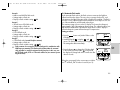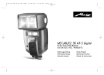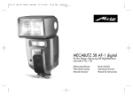
1
MECABLITZ 58 AF-2 digital
für/for Nikon-Digitalkameras,
incl. CLS-System
Bedienungsanleitung
Gebruiksaanwijzing
Manuale istruzioni
Mode d’emploi
Operating instruction
Manual de instrucciones
709 47 0159.A1 58AF-2 Ni Print
ķ
26.07.2010
14:13 Uhr
Seite 114
1 Safety instructions . . . . . . . . . . . . . . . . . . . . . . . . . . . . . . . . . . . . . . . . . . . . . . .115
2 Dedicated flash functions . . . . . . . . . . . . . . . . . . . . . . . . . . . . . . . . . . . . . . . . . .116
2.1 Division into camera groups . . . . . . . . . . . . . . . . . . . . . . . . . . . . . . . . . . . . . . .116
3 Preparing the flash unit for use . . . . . . . . . . . . . . . . . . . . . . . . . . . . . . . . . . . . .117
3.1 Mounting the flash unit . . . . . . . . . . . . . . . . . . . . . . . . . . . . . . . . . . . . . . . . . .117
3.2 Power supply . . . . . . . . . . . . . . . . . . . . . . . . . . . . . . . . . . . . . . . . . . . . . . . . .117
3.3 Switching the flash unit on and off . . . . . . . . . . . . . . . . . . . . . . . . . . . . . . . . . .117
3.4 Power Pack P76 (optional accessory) . . . . . . . . . . . . . . . . . . . . . . . . . . . . . . . .118
3.5 Auto OFF for the flash unit . . . . . . . . . . . . . . . . . . . . . . . . . . . . . . . . . . . . . . .118
4 Display illumination . . . . . . . . . . . . . . . . . . . . . . . . . . . . . . . . . . . . . . . . . . . . . .118
5 Operating modes (mode menu) . . . . . . . . . . . . . . . . . . . . . . . . . . . . . . . . . . . . .118
5.1 Adjusting procedure for flash operating modes . . . . . . . . . . . . . . . . . . . . . . . . .118
5.2 TTL flash mode . . . . . . . . . . . . . . . . . . . . . . . . . . . . . . . . . . . . . . . . . . . . . . . .119
5.3 TTL fill-in flash mode . . . . . . . . . . . . . . . . . . . . . . . . . . . . . . . . . . . . . . . . . . . .120
5.4 Automatic flash mode . . . . . . . . . . . . . . . . . . . . . . . . . . . . . . . . . . . . . . . . . . .121
5.5 Automatic fill-in flash mode . . . . . . . . . . . . . . . . . . . . . . . . . . . . . . . . . . . . . . .122
5.6 Manual flash mode . . . . . . . . . . . . . . . . . . . . . . . . . . . . . . . . . . . . . . . . . . . . .122
5.7 Strobe flash mode . . . . . . . . . . . . . . . . . . . . . . . . . . . . . . . . . . . . . . . . . . . . . .122
6 Flash parameters (Parameter menu) . . . . . . . . . . . . . . . . . . . . . . . . . . . . . . . . . .124
6.1 Setting procedure for the flash parameters . . . . . . . . . . . . . . . . . . . . . . . . . . . .124
6.2 Aperture (F) . . . . . . . . . . . . . . . . . . . . . . . . . . . . . . . . . . . . . . . . . . . . . . . . . .125
6.3 Main reflector position (Zoom) . . . . . . . . . . . . . . . . . . . . . . . . . . . . . . . . . . . . .125
6.4 Flash exposure correction (EV) . . . . . . . . . . . . . . . . . . . . . . . . . . . . . . . . . . . . .126
6.5 Light sensitivity (ISO) . . . . . . . . . . . . . . . . . . . . . . . . . . . . . . . . . . . . . . . . . . . .126
6.6 Manual partial light output (P) . . . . . . . . . . . . . . . . . . . . . . . . . . . . . . . . . . . . .127
7 Special functions (Select menu) . . . . . . . . . . . . . . . . . . . . . . . . . . . . . . . . . . . . . .127
7.1 Setting procedure for the special functions . . . . . . . . . . . . . . . . . . . . . . . . . . . . .127
7.2 Beep function (Beep) . . . . . . . . . . . . . . . . . . . . . . . . . . . . . . . . . . . . . . . . . . . .128
7.3 Flash Bracketing Series (FB) . . . . . . . . . . . . . . . . . . . . . . . . . . . . . . . . . . . . . . .129
7.4 Extended Zoom Mode (Zoom Ext) . . . . . . . . . . . . . . . . . . . . . . . . . . . . . . . . . . .129
7.5 Adjusting exposure format (Zoom Size) . . . . . . . . . . . . . . . . . . . . . . . . . . . . . . .130
7.6 Cordless remote mode (Remote) . . . . . . . . . . . . . . . . . . . . . . . . . . . . . . . . . . . .131
7.7 Meter-Feet changeover (m/ft) . . . . . . . . . . . . . . . . . . . . . . . . . . . . . . . . . . . . . .131
7.8 Secondary reflector . . . . . . . . . . . . . . . . . . . . . . . . . . . . . . . . . . . . . . . . . . . . .132
7.9 Modelling Light (ML) . . . . . . . . . . . . . . . . . . . . . . . . . . . . . . . . . . . . . . . . . . . .132
7.10 Auto OFF Function (Standby) . . . . . . . . . . . . . . . . . . . . . . . . . . . . . . . . . . . . .133
7.11 Key-Lock . . . . . . . . . . . . . . . . . . . . . . . . . . . . . . . . . . . . . . . . . . . . . . . . . . . .134
7.12 AF-BEAM (AF auxiliary light) . . . . . . . . . . . . . . . . . . . . . . . . . . . . . . . . . . . . . 134
8 Motor Zoom Reflector . . . . . . . . . . . . . . . . . . . . . . . . . . . . . . . . . . . . . . . . . . . .135
9 Wide-angle diffuser . . . . . . . . . . . . . . . . . . . . . . . . . . . . . . . . . . . . . . . . . . . . . .135
114
10 Flash techniques . . . . . . . . . . . . . . . . . . . . . . . . . . . . . . . . . . . . . . . . . . . . . . .136
10.1 Bounce flash . . . . . . . . . . . . . . . . . . . . . . . . . . . . . . . . . . . . . . . . . . . . . . . . .136
10.2 Bounce flash with a reflector card . . . . . . . . . . . . . . . . . . . . . . . . . . . . . . . . . .136
10.3 Bounce flash with secondary reflector . . . . . . . . . . . . . . . . . . . . . . . . . . . . . . .136
10.4 Close-ups / macro shots . . . . . . . . . . . . . . . . . . . . . . . . . . . . . . . . . . . . . . . .136
10.5 Manual flash exposure corrections . . . . . . . . . . . . . . . . . . . . . . . . . . . . . . . . .137
11 Flash readiness indication . . . . . . . . . . . . . . . . . . . . . . . . . . . . . . . . . . . . . . . .137
12 Automatic flash sync speed control . . . . . . . . . . . . . . . . . . . . . . . . . . . . . . . . . .137
13 Correct exposure indication . . . . . . . . . . . . . . . . . . . . . . . . . . . . . . . . . . . . . . .138
14 Underexposure warning in TTL flash mode . . . . . . . . . . . . . . . . . . . . . . . . . . . .138
15 Displays in the camera viewfinder . . . . . . . . . . . . . . . . . . . . . . . . . . . . . . . . . .138
16 Flash range indication . . . . . . . . . . . . . . . . . . . . . . . . . . . . . . . . . . . . . . . . . . .139
16.1 Automatic adjustment of the flash range indication . . . . . . . . . . . . . . . . . . . . .139
16.2 Manual adjustment of the flash range indication . . . . . . . . . . . . . . . . . . . . . . .139
16.3 „FEE“ error indication on the flash unit’s LC display . . . . . . . . . . . . . . . . . . . . .139
16. 4 Guide number indication when using lenses without CPU . . . . . . . . . . . . . . . .139
17 Flash exposure memory . . . . . . . . . . . . . . . . . . . . . . . . . . . . . . . . . . . . . . . . . .140
18 Flash synchronisation . . . . . . . . . . . . . . . . . . . . . . . . . . . . . . . . . . . . . . . . . . . .140
18.1 Normal synchronisation . . . . . . . . . . . . . . . . . . . . . . . . . . . . . . . . . . . . . . . . .140
18.2 Second curtain synchronisation (rear mode) . . . . . . . . . . . . . . . . . . . . . . . . . .104
18.3 Slow synchronisation (SLOW) . . . . . . . . . . . . . . . . . . . . . . . . . . . . . . . . . . . .104
18.4 Automatic FP high-speed synchronisation . . . . . . . . . . . . . . . . . . . . . . . . . . . .141
19 Preflash function for red-eye reduction . . . . . . . . . . . . . . . . . . . . . . . . . . . . . .141
20 Multi-zone AF measuring beam . . . . . . . . . . . . . . . . . . . . . . . . . . . . . . . . . . . .141
21 Wireless remote operation . . . . . . . . . . . . . . . . . . . . . . . . . . . . . . . . . . . . . . . .142
21.1 Switching remote operation on and off . . . . . . . . . . . . . . . . . . . . . . . . . . . . . .142
21.2 Settings on the master flash unit . . . . . . . . . . . . . . . . . . . . . . . . . . . . . . . . . . .143
21.3 Settings on the slave flash unit . . . . . . . . . . . . . . . . . . . . . . . . . . . . . . . . . . . .143
21.4 Testing remote operation . . . . . . . . . . . . . . . . . . . . . . . . . . . . . . . . . . . . . . . .143
21.5 SERVO mode . . . . . . . . . . . . . . . . . . . . . . . . . . . . . . . . . . . . . . . . . . . . . . . .144
22 Care and maintenance . . . . . . . . . . . . . . . . . . . . . . . . . . . . . . . . . . . . . . . . . . .145
22.1 Firmware updates . . . . . . . . . . . . . . . . . . . . . . . . . . . . . . . . . . . . . . . . . . . . .145
22.2 Reset . . . . . . . . . . . . . . . . . . . . . . . . . . . . . . . . . . . . . . . . . . . . . . . . . . . . . .145
22.3 Flash capacitor forming . . . . . . . . . . . . . . . . . . . . . . . . . . . . . . . . . . . . . . . . .145
23 Troubleshooting . . . . . . . . . . . . . . . . . . . . . . . . . . . . . . . . . . . . . . . . . . . . . . . .145
24 Technical data . . . . . . . . . . . . . . . . . . . . . . . . . . . . . . . . . . . . . . . . . . . . . . . . .148
25 Optional accessories . . . . . . . . . . . . . . . . . . . . . . . . . . . . . . . . . . . . . . . . . . . .149
Table 3: Guide numbers at maximum light output (P 1) . . . . . . . . . . . . . . . . . . . . . . .222
Table 4: Flash durations at the individual partial light output levels . . . . . . . . . . . . . .223
Table 5: Camera shutter speeds in stroboscopic mode . . . . . . . . . . . . . . . . . . . . . . .224
Table 6: Recycling times and number of flashes with different battery types . . . . . . . .225
Table 7: Maximum guide numbers at HSS-Mode . . . . . . . . . . . . . . . . . . . . . . . . . . .225
709 47 0159.A1 58AF-2 Ni Print
26.07.2010
14:13 Uhr
Seite 115
Introduction
Thank you for purchasing a Metz product. We are happy to welcome you as a
customer.
Of course, you are excited to start using the flash unit right away. However, it is
worthwhile reading the operating instructions first to learn how to use the flash
correctly.
This flash unit is suited for:
• Analog and digital Nikon cameras with TTL, D-TTL, and i-TTL flash control.
• Digital Fuji SLR cameras „Fuji FinePix S2Pro“, „Fuji FinePix S3Pro“.
☞ This flash unit is not suited for other brands of cameras.
Also take a look at the image page at the end of the manual.
1 Safety instructions
• The flash unit is intended and approved exclusively for photographic use!
• Never fire a flash in the vicinity of flammable gases or liquids (petrol, solvents, etc.)! DANGER OF EXPLOSION!
• Never take flash shots of car, bus or train drivers, or of motorcycle and
bicycle riders while they are in motion. They could be blinded by the flash
and cause an accident!
• Never fire a flash in the immediate vicinity of the eyes! A flash fired into the
eyes of a person or animal at close range may damage the retina and lead
to severe visual disorders, including blindness!
• Only use the approved power sources listed in the Operating Instructions!
• Do not expose batteries to excessive heat sources such as sunshine or fire!
• Never throw flat/dead batteries onto a fire!
• Dead batteries should be removed from the flash unit immediately, as lye
leaking from dead batteries can damage the flash unit.
• Never recharge dry cell batteries!
• Do not expose the flash unit or battery charger to dripping or splashing
water such as rain!
• Protect the flash unit from excessive heat and humidity! Do not store the
flash unit in the glove compartment of a car.
• When a flash is fired, no opaque material may be in front of or directly on
the reflector screen of the flash unit, nor may there be dirt on the reflector
screen. The high heat generated by the flash can cause such material to
burn or cause damage to the reflector screen.
• Do not touch the reflector screen after a series of flash shots, as you may
burn yourself.
• Never disassemble the flash unit! DANGER: HIGH VOLTAGE!
There are no components inside the flashgun that can be repaired by a layman.
• When taking a series of flash shots at full light output and with the rapid
recycling times possible with NiMH battery operation, make sure to wait for
at least 10 minutes after 15 flashes. Otherwise, the flash unit will be overloaded.
• This flash unit may be used in combination with a camera-integrated flash
only if the flash can be folded out completely.
• Rapid changes in temperature may lead to condensation. If this occurs,
allow time for the unit to become acclimatized.
• Never use defective batteries of any type with this flash unit.
115
ķ
709 47 0159.A1 58AF-2 Ni Print
26.07.2010
14:13 Uhr
Seite 116
2 Dedicated flash functions
Dedicated flash functions are flash functions that have been specially adapted to
a given camera system. Depending on the type of camera, different flash functions are supported.
2.1 Division into camera groups
ķ
Nikon cameras can be subdivided into the following groups with regard to
their dedicated flash functions:
Cameras from Group A
Cameras without digital data transfer to the
flash unit
e.g. Nikon F601, F601M, F60, F50, FM-3A
Digitale Kompaktkameras “Nikon - Coolpix”
Cameras from Group B
Cameras with digital data transfer to the flash
unit
e.g. Nikon F4, F4s, F801, F801s
Cameras from Group C
Cameras with digital data transfer to the flash
unit and 3D multi-sensor fill-in flash mode
e.g. Nikon F5, F100, F90X, F90, F80, F 75,
F70,
Fuji FinePix S2Pro
Cameras from Group D
Digital Nikon single-lens reflex cameras with
D–TTL flash mode (without CLS) e.g. D1, D1x,
D1H, D100, Fuji FinePix S3Pro
Cameras from Group E
Digital Nikon SLR cameras with i-TTL flash mode
(CLS compatible Cameras)
e.g. D2Hs, D2x, D2xs, D3, D3x, D40, D40x,
D50, D60, D70, D70S, D80, D90, D200,
D300, D700, D3000, D5000, F6,
Fuji FinePix S5Pro, Coolpix 8400, 8800,
P5000, P5100
Table 1
116
Camera Group
Dedicated Flash Functions
AB C D E
• • • • • Flash-ready indicator in camera viewfinder/camera display
• • • • • Correct exposure indicator in camera viewfinder /camera display
• • • Underexposure indicator EV in LC display of the flash unit
• • • • • Automatic flash sync speed control
• • •
TTL flash control Standard TTL without measuring preflash)
• • • • • Automatic fill-in flash control
• •
Matrix-controlled TTL fill-in flash mode
•
3D multi-sensor fill-in flash mode
•
D-TTL and D-TTL 3D flash mode
• i-TTL and I-TTL-BL flash mode
• Flash exposure measurement memory for i-TTL and I-TTL-BL
• • • • Manual TTL/D-TTL/i-TTL flash exposure correction
• • • 1st or 2nd curtain synchronisation (REAR)
• Automatic FP short sync for i-TTL, I-TTL-BL and M
• • • • Automatic motor zoom control
• • • • Extended zoom mode
• • • • • Automatic AF measuring beam control
• • • • Automatic flash range indicator
• • • • • Programmed auto flash mode
• • • Preflash for red-eye reduction
• • • Triggering control / auto flash
• Wireless remote flash mode
(Advanced Wireless Remote Flash Mode Lighting)
• • • • • Wake-up function for the flash unit
• Adjusting exposure format (Zoom Size)
☞ It is impossible to describe all camera types and their individual dedica-
ted flash functions within the scope of these instructions. Therefore, please refer to the flash mode description in your camera’s operating instructions to find out which functions are supported and which ones have to
709 47 0159.A1 58AF-2 Ni Print
26.07.2010
14:13 Uhr
Seite 117
be set manually on the camera. Using lenses not equipped with a CPU
(i.e., lenses without auto focus mode), results in certain functional limitations.
3 Preparing the flash unit for use
3.1 Mounting the flash unit
Mounting the flash unit on the camera
☞ Turn off the camera and flash before mounting or removing.
• Turn the knurled nut towards the flash unit housing as far as it will go. The
locking pin in the adapter shoe is now fully retracted into the case.
• Slide the flash unit foot completely into the camera accessory shoe.
• Turn the knurled nut towards the camera housing as far as it will go, clamping the flash unit in place. If the camera does not have a locking hole, the
spring-loaded locking pin retracts into the adapter case so as not to damage
the surface.
Removing the flash unit from the camera
☞ Turn off the camera and flash before mounting or dismounting.
• Turn the knurled nut towards the flash unit housing as far as it will go.
• Remove the flash unit from the camera’s accessory shoe.
3.2 Power supply
Suitable batteries/rechargeable batteries
The flash unit can be operated with any of the following batteries:
• 4 NiCad batteries 1.2V, type IEC KR 15/51 (KR6, size AA). They permit very
fast recycling times and are economical in use because they are rechargeable.
• 4 nickel-metal-hydride batteries 1.2V, type HR6 (size AA). They have a significantly higher capacity than NiCad batteries and are less harmful to the environment, since they have no cadmium.
• 4 alkaline-manganese dry cell batteries 1.5V, type IEC LR6 (size AA).
Maintenance-free power source for moderate power requirements.
• 4 lithium batteries 1.5V, type IEC FR6 L91 (size AA). Maintenance-free highcapacity power source with a low self-discharge rate.
• Power Pack P76 with connecting cable V58-50 (optional accessory)
☞ If your flash unit is not going to be used for an extended period of time,
remove the batteries.
Replacing batteries
The batteries are flat or dead if the recycling time (elapsing from the triggering
of a full-power flash, e.g. in the M mode, to the moment the flash ready indicator lights up again) exceeds 60 seconds.
• Turn off the flash unit at the main switch .
• Slide the battery compartment cover downwards and fold open.
• Insert the batteries lengthwise as indicated by the battery symbols on the flash
unit, and close the battery compartment cover .
☞ When inserting batteries, ensure that the polarity is correct and matches
the symbols in the battery compartment. Inserting the batteries in the
wrong direction can destroy the flash unit!
Always replace all batteries simultaneously, and make sure that batteries
are the same brand and have the same capacity.
Flat or dead batteries should not be disposed of with ordinary household waste. Help protect the environment, and dispose of flat/dead batteries at the appropriate collection points.
3.3 Switching the flash unit on and off
✴
The flash unit can be turned on by flipping the main
switch to the „ON“ position.
To turn off the flash unit, flip the main switch to the
left position.
☞ If your flash unit is not going to be used for an extended period of time,
we recommend turning it off with the main switch and removing the
power source (i.e., batteries).
117
ķ
709 47 0159.A1 58AF-2 Ni Print
26.07.2010
14:13 Uhr
Seite 118
3.4 Power Pack P76 (optional accessory)
If a battery-operated flash does not meet your needs in terms of number of flashes and recycling times, a Power Pack P76 (optional) can be connected to the
flash unit to provide extra power. A V58-50 connecting cable (optional) is
necessary for connecting the Power Pack P76 to the flash unit.
☞ In this case, no batteries have to be inserted into the flash unit.
When attaching the Power Pack P76 or the V58-50 connecting cable (accessory)
to the flash unit, the main switch of the flash must be in the left „OFF“ position.
The flash unit is then turned on or off using the switch on the Power Pack P76
(see Operating Instructions for the Power Pack).
☞ To protect the flash unit from thermal overload when connected to the
Power Pack, a monitoring control increases the recycling times during
heavy usage. Both flash unit and Power Pack should be switched off
before the connecting cable is attached or removed from either unit.
3.5 Auto OFF for the flash unit
ķ
To save battery power and prevent inadvertent battery drain, the flash unit is
factory-set to automatically switch to standby mode (Auto OFF) 10 minutes after
• being switched on,
• a flash is fired
• the shutter release is actuated
• the camera’s exposure metering system is switched off.
...The flash readiness indicator and the LC display are also switched off.
If the flash is manually switched on again, the last settings prior to the automatic
switch off are retained and immediately available. The flash unit can be reactivated by pressing any button or by lightly depressing the shutter release (wake
up function).
☞ The flash unit should always be turned off using the main switch if it
is not going to be used for an extended period.
If necessary, the Auto OFF function can be set to occur after 1 minute of inactivity, or can be deactivated (see 7.9).
118
4 Display illumination
Every time a button on the flash unit is pressed, the flash display illumination is
activated for 10 seconds. When a flash is fired via the camera or a hand
release, the display lightning on the flash unit is switched off.
For some cameras in Groups C, D and E, when the flash unit display illumination is switched on the camera is automatically switched on as well. The inverse
is true as well: when the camera display illumination switches on, the flash illumination is also activated.
5 Operating modes (mode menu)
The flash unit supports TTL , automatic A , manual M , and stroboscope
modes
.
Depending
on the type of camera, other flash modes may be supported.
☞
These flash operating modes can be selected and activated in the mode
menu following a data transfer with the camera.
5.1 Adjusting procedure for flash operating modes
• Press the Mode button until the word „Mode“ appears on the display. You
can choose from the following operating modes:
TTL
TTL flash mode or D-TTL / i-TTL
TTL BL TTL fill-in flash modes or D-TTL-3D / i-TTL-BL (depending on type of
camera)
A
Automatic flash mode
M
Manual flash mode
Stroboscope flash mode
26.07.2010
14:13 Uhr
Seite 119
• Set the flash mode of your choice ( TTL , automatic
A , manual M l, etc.) using the
and arrows. The flash mode you choose is
Set
then highlighted. The settings take effect immediately.
• Press the button
, and the display changes back
to the normal view. If the button
is not pressed,
the display will change back to the normal view after
about 5 seconds.
Flash operation with Group A cameras (see table 1)
The flash parameters for ISO, aperture and lens focal length or mirror position
have to be set by hand (see 6). The range indicator on the display matches the
set flash parameters.
Flash operation with Group B, C, D and E cameras (see table 1)
The flash parameters for ISO, aperture and lens focal length or mirror position
are set automatically if the camera transfers the necessary data to the flash unit.
The range indicator on the display of the matches the flash parameters transferred from the camera.
☞ If the camera does not transfer one or more flash parameters to the flash
unit, you will have to adjust these settings by hand (see 6).
TTL BL
A
M
☛
Mode
5.2 TTL flash mode
The TTL flash mode offers a very simple method of achieving excellent flash
shots. In this mode, exposure readings are taken by a sensor built into the
camera which measures the amount of light through the camera lens (TTL). The
electronic control circuit within the camera transmits a stop signal to the flash
unit after sufficient light has been emitted, instantly interrupting the flash. The
advantage of this flash mode is that all factors influencing correct exposure (filters, change of aperture and focal length with zoom lenses, extensions for closeups, etc.) are automatically taken into account.
TTL flash mode is supported by all modes of camera operation (such as „P“ for
fully automatic settings, „A“ for aperture priority mode, „S“ for shutter priority
mode, vari or scene modes, and „M“ for manual mode).
Setting procedure:
Mode
• Press the Mode button until „Mode“ flashes on the
LC display.
• Set the TTL flash mode using the and arrows. The flash mode you choose is then highlighted.
The setting takes effect immediately.
TTL
A
A
Set
☛
709 47 0159.A1 58AF-2 Ni Print
• Press the button
to change the display back to
the normal view.
If the button
is not pressed, the display will change back to the normal view after about 5 seconds.
F 5.6
TTL
AZoom 28
7.7 m
Mode
ISO 100
Para
Sel
☞ Standard TTL flash mode is only supported by
cameras in Groups A, B and C.
D-TTL and I-TTL flash modes
D-TTL and I-TTL flash modes are advanced variants of the normal TTL flash
modes used with analog cameras. These modes are supported by Groups D
and E cameras (see table1). Prior to shooting, the flash unit fires a series of
barely visible measuring pre-flashes. The camera evaluates the reflected preflash light so that the subsequent flash exposure is optimally adapted to the prevailing photographic situation (see your camera’s operating instructions).
When the TTL flash mode is selected from the „mode menu“, the flash unit automatically activates standard TTL, D-TTL or i-TTL flash mode, depending on the
TTL
type of camera (see tables 1 and 2). After the settings are confirmed,
will appear in the flash unit display for D-TTL or i-TTL flash modes.
119
ķ
709 47 0159.A1 58AF-2 Ni Print
26.07.2010
14:13 Uhr
Seite 120
Setting procedure:
Mode
Set
☛
TTL
A
A
F 5.6
TTL
AZoom 35
12 m
Mode
ķ
ISO 200
✴
Para
Sel
• Press the Mode button until „Mode“ flashes on the
LC display.
TTL using the and • Set the flash mode
arrows. The flash mode you choose is then highlighted.
The setting takes effect immediately.
• Press the button
to change the display back to
the normal view. If the button
is not pressed, the
display will change back to the normal view after
about 5 seconds.
If the shot was properly lit, the correct exposure indication will flash „OK“ for about 3 seconds (see 13).
To test the TTL function with analog cameras, a roll of film has to be in the
camera. Please note whether there are limitations for your camera in
terms of film sensitivity or ISO (i.e., maximum ISO 1000) for TTL flash
operation (see your camera’s operating instructions).
5.3 TTL fill-in flash mode
Fill-in flash TTL BL overcomes troublesome dense shadows for daylight shots
and produces a more balanced exposure between subject and background with
contre-jour shots. The camera’s computer-controlled metering system sets the
most suitable combination of shutter speed, aperture and flash output. When
using a camera from Groups C, D and E (see table 1) with a D-AF Nikkor lens,
the distance to the subject is also calculated into the optimal flash performance.
120
• Press the Mode button until „Mode“ flashes on the
LC display.
• Set the TTL BL flash mode using the and arrows. The flash mode you choose is then highlighted.
The setting takes effect immediately.
TTL BL
A
A
Set
☛
Mode
☞
Setting procedure:
TTL BL
F 5.6
AZoom 35
• Press the button
to change the display back to
12 m
ISO 200
the normal view. If the button
is not pressed, the
Mode Para
Sel
display will change back to the normal view after
about 5 seconds.
If the shot was properly lit, the correct exposure indication will flash „OK“ for about 3 seconds (see 13).
☞ Ensure that the contre-jour light source does not shine directly into the
lens, as this will interfere with the camera’s TTL metering system.
Depending on the camera model, the suitable fill-in flash mode will be automatically activated after TTL BL flash mode has been set:
Group A:
• Automatic fill-in flash mode or matrix-controlled fill-in flash mode
• Either set automatically or manually on the camera (see camera’s operating
instructions)
• Display on flash unit: TTL
• No extra settings are necessary on the flash unit, nor is there any display for
this mode.
✴
26.07.2010
14:13 Uhr
Seite 121
Group B:
• Matrix-controlled fill-in flash mode.
• Settings made on flash unit.
• Display on flash unit after saving: TTL BL
Group C:
• 3D multi-sensor fill-in flash mode.
• Settings made on flash unit.
TTL BL
• Display on flash unit after saving:
Group D:
• D-TTL 3D flash mode.
• Settings made on flash unit.
TTL BL
• Display on flash unit after saving:
Group E:
• i-TTL BL flash mode (not with Coolpix cameras).
• Settings made on flash unit.
TTL BL
• Display on flash unit after saving:
Some
cameras
do
not
support
TTL
fill-in
flash mode in combination with
☞
SPOT exposure metering. This flash mode will then either be automatically cancelled or cannot be activated in the first place. In this case, normal TTL flash mode, D-TTL or i-TTL modes will be set (see camera’s operating instructions).
5.4 Automatic flash mode
In the automatic flash mode A, the flash unit sensor measures the light that
reflects back from the subject. The sensor has a coverage of about 25°, and
only measures the light for the time a flash is fired by the mecablitz. The flash is
cut off as soon as sufficient light has been emitted for correct exposure. The sensor of the mecablitz has to be directed at the subject.
The maximum range is shown on the LC display. The shortest shot distance is
approximately 10% of the maximum distance range. The subject should be located within the middle third of the distance range shown on the LC display to
allow the electronic system sufficient leeway for compensation.
Setting procedure:
TTL BL
A
M
Mode
• Press the Mode button until „Mode“ flashes on the
LC display.
• Set the flash mode A using the and arrows. The flash mode selected is then highlighted.
The setting takes effect immediately.
Set
☛
709 47 0159.A1 58AF-2 Ni Print
• Press the button
to change the LC display back
to the normal view. If the button
is not pressed,
the display will change back to the normal view after
about 5 seconds.
F 4.5
A
AZoom 70
14 m
Mode
ISO 200
✴
Para
Sel
If the shot was properly lit, the correct exposure indication will flash „OK“ for about 3 seconds (see 13).
121
ķ
26.07.2010
14:13 Uhr
Seite 122
5.5 Automatic fill-in flash mode
When shooting in automatic fill-in flash mode in daylight, the automatic flash
mode A will automatically set a correction of between -1 and -2 f-stops to
compensate for flash exposures (see 6.4 and 10.5).
This has a graduated lightening effect on shadowy areas, which has a natural
appearance on the photograph.
5.6 Manual flash mode
In the manual flash mode M , the flash unit emits the full uncontrolled amount
of light if no partial light output has been selected. The specific photographic
situation can be taken into account by making adjustments to the aperture setting or by selecting a suitable partial light setting.
Setting procedure:
TTL BL
A
M
Mode
Set
☛
ķ
F 4.0
M
MZoom 24
10 m
Mode
122
• Press the Mode button until „Mode“ flashes on the
LC display.
• Choose the flash mode M using the and arrows. The flash mode M is then highlighted.
The setting takes effect immediately.
ISO 200
Para
Sel
• Press the button
to change the LC display back to
the normal view. If the button
is not pressed, the
display will change back to the normal view after
about 5 seconds.
Set partial light output:
M
F 4.0
MZoom 24
• Press the Para button (Parameters ) until „P“ flashes
0,6 m
P1/8
on the LC display for partial light output.
+
Para
–
• Set the desired light output (1/1-1/256) with the
+ and – buttons. The setting takes effect immediately.
• Press the button
to change the LC display back to
the normal view. If the button
is not pressed,
the display will change back to the normal view after about 5 seconds.
The mecablitz LC display will indicate the flash-to-subject distance required for a
correct flash exposure.
☞ Some cameras only support the M manual flash mode when the
camera is set to the manual operating mode M.
☛
☛
709 47 0159.A1 58AF-2 Ni Print
5.7 Strobe flash mode
The strobe flash mode
is a manual flash mode. It allows several flash exposures to be made on a single photo, which can be especially interesting for
movement studies or special effect images. In strobe flash mode, several flashes
at a certain flash frequency are emitted. For this reason, this function is only
possible with a partial light output of 1/4 or less.
The flash frequency (flashes per second) for a stroboscope image can be set between 1 ... 50 Hz in 1 Hz intervals, and the number of flashes can be set between 2 ... 50 in intervals of one.
Seite 123
Setting procedure:
A
M
Mode
Set
☛
• Press the Mode button until „Mode“ flashes on the
LC display.
• Choose the flash mode
using the and arrows. The flash mode
is then highlighted. The
setting takes effect immediately.
N24:f10Hz
AZoom 24
1.2 m
Mode
P1/32
Para
Sel
• Press the button
to change the LC display back to
the normal view. If the button
is not pressed, the
display will change back to the normal view after
about 5 seconds.
Strobe number of flashes (N)
In strobe mode, the number of flashes per shot (N) can be selected.
The number of flashes can be set from 2 to 50 in intervals of one. The maximum
manual partial light output is automatically adjusted to this number.
Strobe flash frequency (f)
Strobe mode allows you to select the flash frequency (f), which indicates the
number of flashes per second. The number of flashes can be set from 2 to 50 in
intervals of one. The maximum manual partial light output is automatically adjusted to this number.
Setting procedure:
• Press the Para button (Parameters) until the desired
N24
flash parameter (N or f) flashes on the LC display.
2.1 m
• Set the desired value using the + and – but+
Para
–
tons. The setting takes effect immediately.
• Press the button
to change the LC display back
to the normal view. If the button
is not pressed,
the display will change back to the normal view after
about 5 seconds.
The maximum possible partial light output depends on the ISO and aperture settings, and is automatically set in strobe mode. If you desire short flashes, you
can manually reduce the partial light output to the lowest value of 1/256.
The mecablitz LC display will indicate the flash-to-subject distance required for a
correct flash exposure, given the parameters selected. By changing the aperture
setting or the partial light output, this value can be adjusted to fit the actual
distance to the subject.
Setting procedure:
F 4.0
• Press the Para button (Parameters) until the desired
MZoom 24
flash parameter
4,6
m
P1/1
(F=f-stop or P=partial light output) appears on the
+
Para
–
LC display.
• Set the desired value using the + and – buttons. The setting takes effect immediately.
• Press the button
to change the LC display back to
the normal view. If the button
is not pressed, the
display will change back to the normal view after
about 5 seconds.
☞ Aperture and ISO settings do not appear on the 2.1 m Para P1/32
+
–
LC display in strobe mode. Strobe mode may not
be combined with an operational second reflector.
☛
14:13 Uhr
☛
☛
26.07.2010
☛
709 47 0159.A1 58AF-2 Ni Print
123
ķ
709 47 0159.A1 58AF-2 Ni Print
26.07.2010
14:13 Uhr
Seite 124
6 Flash parameters (Parameter menu)
For the flash unit to operate correctly, various flash parameters such as the
zoom position of the main reflector, aperture, ISO light sensitivity, etc. have to
be adjusted to match the camera.
When using the flash unit with cameras in Group A (see table 1), these parameters have to be set by hand.
For cameras in Groups B, C, D, or E, the flash parameters are set automatically
if the camera is equipped with a CPU-capable lens and transfers the necessary
data to the flash unit. For this automatic data transfer to occur, the flash unit has
to be mounted on the camera, and both devices have to be switched on. In addition, a data exchange between the camera and flash unit has to be initiated, for
which you simply briefly press the shutter release. The maximum range as per
the current flash parameters is shown on the display.
6.1 Setting procedure for the flash parameters
ķ
☞ When a button is pressed for the first time, the LC display is illuminated.
Depending on the flash mode set, various flash parameters are shown in the
menu: For cameras with digital data transfer, the flash parameters for aperture
(F), lens focal length (Zoom), and light sensitivity (ISO) are automatically set on
the flash unit. The flash parameters for aperture (F) and light sensitivity (ISO)
cannot be changed.
☞ If the camera is equipped with a non-CPU capable lens (such as a lens
without autofocus), the flash parameters for aperture (F) and focal length
(Zoom) have to be set manually on the flash unit.
124
Press the Para button (Parameters) until the desired flash parameter (see
below) appears on the LC display.
The following parameters are available:
TTL TTL-BL A
M
—
—
—
—
F
Zoom
N
Number of strobe flashe
—
f
Strobe flash frequency
P
P
Manual partial light output
F
F
Aperture
Zoom Zoom Mainreflektor position
EV
—
—
Manual flash exposure correction
ISO
ISO
ISO
Light sensitivity
• Set the desired value using the + and – buttons. The setting takes effect
immediately.
• Press the button
to change the LC display back to the normal view. If the
button
is not pressed, the display will change back to the normal view
after about 5 seconds.
709 47 0159.A1 58AF-2 Ni Print
26.07.2010
14:13 Uhr
Seite 125
6.2 Aperture (F)
6.3 Main reflector position (Zoom)
If there is no digital data transfer between the camera and flash unit, for example with cameras from Group A (see table 1) or when using non-CPU-capable
lenses, the aperture can be manually set from 1.0 to 45 (at ISO 100), in full fstop intervals. For flash modes A (automatic) and M (manual), the camera and
flash unit have to be set to the same aperture.
Setting procedure:
If there is no digital data transfer between the camera and flash unit, for example with cameras from Group A (see table 1) or when using non-CPU- capable
lenses, the reflector positions 24 mm - 28 mm - 35 mm - 50 mm - 70 mm 85 mm - 105 mm (35mm format 24 x 36) can be set manually.
MZoom will then appear in the LC display.
Setting procedure:
7,7 m
Para
Sel
☛
Mode
ISO 200
F 8.0
A
AZoom 70
3,8 m
ISO 200
Para
–
• Set the desired value using the + and – buttons.
The setting takes effect immediately.
+
• Press the button
to change the LC display back
to the normal view. If the button
is not pressed,
the display will change back to the normal view after
about 5 seconds.
During digital data transfer between the camera and flash unit, intermediate values are also adjusted. During TTL flash mode, setting the aperture on the flash unit is only necessary to achieve the correct distance range indication, not for the function of the flash.
☛
☞
• Press the Para button (Parameters) until „F“ flashes
on the LC display.
F 8.0
A
• Press the Para button (Parameters) until „MZoom“
appears on the LC display.
• Set the desired value using the + and – buttons. The setting takes effect immediately.
MZoom 35
12 m
ISO 200
Para
–
+
F 8.0
A
MZoom 70
16 m
ISO 200
Para
• Press the button
to change the LC display back to
the normal view. If the button
is not pressed, the
display will change back to the normal view after
about 5 seconds.
–
+
☛
AZoom 70
☛
F 4.0
A
During digital data transfer between the camera and flash unit, the main reflector positions are adjusted automatically.
AZoom will then appear in the LC display.
125
ķ
709 47 0159.A1 58AF-2 Ni Print
26.07.2010
14:13 Uhr
Seite 126
6.5 Light sensitivity (ISO)
Manual flash exposure correction (EV) can help offset extreme differences in
contrast between the subject and background. Corrections from -3 f-stops (EV)
to +3 f-stops (EV) can be made, in 1/3 increments (also see 10.5).
Setting procedure:
If there is no digital data transfer between the camera and flash unit, for example with cameras from Group A (see table 1) or when using non-CPU–capable
lenses, the ISO can be manually set from 6 to 6400.
For flash modes A (automatic) and M (manual), the camera and flash unit
have to be set to the same ISO value.
Setting procedure:
A
F 8.0
MZoom 35
• Press the Para button (Parameters) until „ISO“ flas12 m
ISO 200
hes on the LC display.
+
Para
–
F 8.0
MZoom 35
12 m
EV 0
–
+
• Press the Para button (Parameters) until „EV“ flashes on the LC display.
☛
Para
F 8.0
A
MZoom 35
6,1 m
EV+2
Para
☛
ķ
–
126
• Set the desired EV value using the + and – buttons. The setting takes effect immediately.
• Set the desired ISO value using the + and –
buttons.
The setting takes effect immediately.
F 8.0
A
MZoom 35
+
• Press the button
to change the LC display back to
the normal view. If the button
is not pressed, the
display will change back to the normal view after
about 5 seconds.
• Press the button
to change the LC display back to
the normal view. If the button
is not pressed, the
display will change back to the normal view after
about 5 seconds.
17 m
ISO 400
Para
–
☛
A
☛
6.4 Flash exposure correction (EV)
+
During TTL flash mode, setting the ISO on the flash unit is only necessary to
achieve the correct distance range indication, not for the function of the flash.
26.07.2010
14:13 Uhr
Seite 127
6.6 Manual partial light output (P)
In the manual mode M and the strobe mode
, the light output can also be
adjusted to fit the shooting situation with the manual partial light output parameter (P). Settings in manual flash mode M range from P 1/1 (full light output)
to P 1/256, in intervals of 1/3.
Setting procedure:
F 8.0
M
MZoom 35
17 m
P1/1
–
+
☛
Para
F 8.0
M
MZoom 35
6,1 m
P1/8
Para
☞
☞
• Set the desired light output (1/1-1/256) with the
+ and – buttons.
The setting takes effect immediately.
+
• Press the button
to change the LC display back to
the normal view. If the button
is not pressed, the
display will change back to the normal view after
about 5 seconds.
In strobe mode
, the maximum partial light output is automatically
adjusted to fit the flash parameters chosen.
In strobe mode
, reduction of the manual partial light output is only
possible in full intervals.
When the number of flashes (N) and the flash frequency (f) are reset, the
partial light output is not reset.
☛
☞
–
• Press the Para button (Parameters) until „P“ appears on the LC display.
7 Special functions (Select menu)
Special functions are selected using the Sel (Select) button. Depending on
the camera model and flash mode set, various special functions are available. If
certain special functions are not supported by your camera, these functions may
not be displayed in the menu. Also see table 2 for more information.
7.1 Setting procedure for the special functions
☞ When a button is pressed for the first time, the
Select
LC display is illuminated.
• Press the Sel key repeatedly until „Select“ appeBeep
Mode Para
Sel
ars on the display.
• Use the and arrows to select the item of
your choice or special function from the menu. The
selected menu item will be highlighted against a dark
background.
The following special functions are available, depending on the mode and
camera model:
☛
709 47 0159.A1 58AF-2 Ni Print
TTL TTL-BL A
M
Beep
Beep
Beep
Remote
Remote
Remote
FB
-
-
Standby
Standby
Standby
ML
ML
ML
KEYLOCK
KEYLOCK
KEYLOCK
Zoom Ext
Zoom Ext
Zoom Ext
Zoom Size
Zoom Size
Zoom Size
m / ft
m / ft
m / ft
AF-BEAM
AF-BEAM
AF-BEAM
ķ
-
127
1/1
☛
Set
26.07.2010
14:13 Uhr
Seite 128
• Press the Set key to confirm the special function
selection.
• Choose the setting desired using the and arrows.
The setting takes effect immediately.
• Press the button
repeatedly to return the display
to its normal reading. If the button
is not pressed, the display will change back to the normal view
after about 5 seconds.
Setting procedure:
Select
• Press the Sel button repeatedly until „Select“
appears on the display.
Beep
Remote
Set
• Use the and buttons to select „BEEP“ from
the menu. The selected menu item will be highlighted
against a dark background.
☛
☛
709 47 0159.A1 58AF-2 Ni Print
7.2 Beep function (Beep)
128
• Press the Set key to confirm the special function
selection.
• Choose the setting desired using the and arrows.
The setting takes effect immediately.
• Press the button
repeatedly to return the display
to its normal reading. If the key
not pressed, the
display will switch back to normal automatically
after approximately 5 seconds.
ON
Set
☞ When the beep function is turned on, the
symbol is also displayed on the
LC display.
M
F 4.0
MZoom 24
10 m
ISO 200
☛
☛
ķ
The beep function allows the user to receive an acoustic signal for certain functions of the flash unit. This allows the photographer to concentrate fully on the
subject and taking the picture, and not have to worry about any optical status
indicators.
The beep function signals when the flash is ready, when the correct flash exposure has been reached, or when an error occurs.
Acoustic signals after the flash unit has been turned on:
• A short (about two seconds) uninterrupted beep signal after turning the flash
on indicates that the flash unit is ready.
Beep signals after taking a photograph:
• A short (about two seconds) uninterrupted beep signal directly after a picture
is taken indicates that the shot was exposed correctly and the flash is ready
again. If no beep signal sounds, then the shot was underexposed.
• A broken (– – –) beep signal directly after a shot indicates that the shot was
correctly exposed. The flash is only ready however after a second (about two
seconds) continuous beep.
Beep signals when adjusting automatic mode settings:
• A short beep signal as an alarm in automatic mode indicates that the aperture and ISO settings exceed the permissible light control range. The auto aperture of the mecablitz is then automatically adjusted to the next permissible
value.
709 47 0159.A1 58AF-2 Ni Print
26.07.2010
14:13 Uhr
Seite 129
7.3 Flash Bracketing Series (FB)
A series of flash exposures (flash-bracketing FB) can be carried out in the TTL
and automatic A flash modes. A flash bracketing series consists of
three successive flash shots with different flash exposure correction values.
When a flash bracketing series is set, FB and the correction value appear on the
display. The possible correction values range from 1/3 to 3 apertures in onethird aperture increments.
Setting procedure:
Remote
FB
Standby
Select
Set
☛
☛
FB
11/3
☛
☛
Set
• Press the Sel button repeatedly until „Select“
appears on the display.
• Select the menu option „FB“ by pressing the and buttons. The selected menu option will be
highlighted.
• Confirm the selection of the special function by pressing the Set button.
• Select the desired setting with the and buttons. The setting takes effect immediately.
• Press the button
repeatedly until the screen is
reset to its normal view. If the button
is not pressed, the display is automatically reset to its normal
view after about 5 seconds.
• The first shot is taken without a correcTTL
F 5.1 FB1
FB1
tion value.
AZoom 28
„FB 1“ will also appear on the display.
7.7 m
ISO 100
• The second shot is taken with minus correction.
„FB 2“ and the minus correction value (EV) will also appear on the display.
• The third shot is taken with plus correcTTL
F 5.1 FB2
tion. „FB 3“ and the plus correction
EV– 1/3
AZoom 28
value (EV) will also appear on the
7.7 m
EV– 1/3
display.
• After the third shot, the flash bracketing series is automatically deleted.
„FB“ will disappear from the display.
☞ When the flash bracketing series is set, the correction value is always
shown as a positive value!
Flash bracketing series in the TTL flash mode
A flash bracketing series in the TTL flash mode is only possible if the camera
supports the setting of a manual flash exposure correction on the flash unit (see
camera instruction manual)! Otherwise, the shots are taken without a correction
value!
Flash bracketing in automatic flash mode A
The type of camera is not important for a flash bracketing series in automatic
flash mode A.
7.4 Extended Zoom Mode (Zoom Ext)
In the extended zoom mode, the focal length of the main reflector is reduced to
one level below the focal length of the camera lens. The resulting broader light
coverage provides additional dispersed light (reflections) inside rooms so that a
softer flash illumination is possible.
129
ķ
14:13 Uhr
Seite 130
Example:
The focal length of the camera lens is 50 mm. The extended zoom mode sets a
35 mm reflector position on the flash unit. However, 50 mm continues to be
shown on the display.
• When „Ext ON“ is displayed, the extended zoom mode is activated.
• When „Ext OFF“ is displayed, the extended zoom mode is deactivated.
Setting procedure:
KEYLOCK
m/ft
Zoom Ext
Select
Set
☛
☛
Set
☛
ķ
Ext OFF/ON
TTL
EZoom
• Press the Sel button repeatedly until „Select“
appears on the display.
• Select the menu option „ZoomExt“ by pressing the
and buttons. The selected menu option will
be highlighted.
• Confirm the selection of the special function by pressing the Set button.
• Select the desired setting with the and buttons. The setting takes effect immediately.
• Press the button
repeatedly until the screen is
reset to its normal view. If the button
is not pressed, the display is automatically reset to its normal
view after about 5 seconds.
F 5.6
EZoom 35
12 m
ISO 200
Once the extended zoom mode is activated, „EZoom“ will appear on the display
next to the focal length.
7.5 Adjusting exposure format (Zoom Size)
With some digital cameras it is possible to adjust the light angle of the main
reflector to suit the chip format (the dimensions of the image recording module).
• When „Size ON“ appears, Zoom Size is activated.
• When „Size OFF“ appears, Zoom Size is deactivated.
Setting procedure:
Select
Zoom Ext
• Press the Sel button repeatedly until „Select“
Zoom Size
appears on the display.
m/ft
• Select the menu option „ZoomSize“ by pressing the
Set
and keys. The selected menu option will be
highlighted.
☛
☛
26.07.2010
• Confirm the selection of the special function by pressing the Set button.
Size ON
• Select the desired setting with the and Set
keys. The setting takes effect immediately.
• Press the button
repeatedly until the screen is
reset to its normal view. If the button
is not pressed, the display is automatically reset to its normal
view after about 5 seconds.
TTL
F 5.0
Once the Zoom Size mode is activated,
SZoom 35
„SZoom“ will appear on the display next to SZoom
12 m
ISO 200
the focal length.
☞ Refer to your camera’s instruction manual for further information.
☛
709 47 0159.A1 58AF-2 Ni Print
☞ Depending on the system, the extended zoom mode is supported for lens ☞ The Zoom size function cannot be set with cameras which do not support
focal lengths of 28 mm or more (35mm format). The camera must be
equipped with a CPU lens and be able to transfer data on the lens focal
length to the flash unit.
130
shooting format adjustment!
709 47 0159.A1 58AF-2 Ni Print
26.07.2010
14:13 Uhr
Seite 131
7.6 Cordless remote mode (Remote)
7.7 Meter-Feet changeover (m/ft)
• When „Remote OFF“ appears, the cordless remote mode is deactivated.
• When „Remote Master“ appears, the flash unit is operating as a guiding
master flash unit on the camera.
• When „Remote Slave“ appears, the flash unit is operating completely as a slave flash unit. See also Section 21.
Setting procedure:
The maximum flash range indicated by the flash unit’s display can either be
shown in meters or feet. The setting can be adjusted under the menu option
m/ft.
Setting procedure:
Set
• Confirm the selection of the special function by pressing the Set button.
• Select the desired setting with the and buttons.
The setting takes effect immediately.
Remote
Master
Set
☛
• Press the
button repeatedly until „Select“
appears on the display.
• Select the „Remote“ menu option by pressing the
and buttons. The selected menu option will
be highlighted.
M
A TTL
B TTL+1/3
Para
CH1
AZoom 28
F32
Sel
• Press the button
repeatedly until the screen is
reset to its normal view. If the button
is not pressed, the display is automatically reset to its normal
view after about 5 seconds.
Set
☛
☛
☛
☛
Sel
• Press the Sel button repeatedly until „Select“
appears on the display.
• Select the „m/ft“ menu option by pressing the and buttons. The selected menu option will be
highlighted.
• Confirm the selection of the special function by pressing the Set button.
• Select the desired setting with the and buttons. The setting takes effect immediately.
– When „m“ is displayed, distances will be
shown in meters.
– When „ft“ is displayed, distances will be
shown in feet.
• Press the button
repeatedly until the
display is reset to its normal state. If the
m
button
is not pressed, the display is
automatically reset to its normal view
after about 5 seconds.
m
Set
ķ
☛
BEEP
Remote
FB
Select
Zoom Ext
m/ft
AF-BEAM
Select
F 4.5
A
AZoom 70
14 m
ISO 200
131
709 47 0159.A1 58AF-2 Ni Print
26.07.2010
14:13 Uhr
Seite 132
7.9 Modelling Light (ML)
The secondary reflector is used for frontal brightening in the case of indirect lighting when the main reflector is pivoted to the side or upwards (see 10.3).
If the secondary reflector produces too much light, it can be reduced to 1/2
or 1/4 .
• „ Off“ setting: Secondary reflector is turned off.
• „ P1 / 1“ setting: secondary reflector is operating at full light output.
• „ P1 / 2“ setting: secondary reflector is operating at 1/2 light output.
• „ P1 / 4“ setting: secondary reflector is operating at 1/4 light output.
When the secondary reflector is activated and the setting is saved, a symbol
will appear in the display.
Setting procedure:
The modelling light is a high-frequency stroboscopic flash. It creates the impression of a semi-permanent light for a duration of about 3 seconds. The modelling
light enables the user to assess light distribution and the formation of shadows
before taking pictures.
• The modelling light is activated when „ML ON“ is displayed.
• The modelling light is deactivated when „ML OFF“ is displayed.
Setting procedure:
• Press the Sel button repeatedly until „Select“
Select
Standby
ML
appears on the display.
KEYLOCK
• Select the menu option „ML“ by pressing the Set
and buttons. The selected menu option will be
highlighted.
• Confirm the selection of the special function by pressing the Set button.
• Select the desired setting with the and buttons. The setting takes effect immediately.
ML
• Press the button
repeatedly until the screen is
ON
reset to its normal state. If the button
is not pres
Set
sed, the display is automatically reset to its normal
view after about 5 seconds.
Once the modelling light function is activated, the symbol
is displayed on the flash-ready indicator or the manual firing button. The modelling light is activated when the manual firing button is pressed.
A
F 4.5
☞ When the flash unit functions as
AZoom 70
master in the cordless remote system,
14 m
ISO 200
the activation of the modelling light
Mode Para
Sel
also activates the modelling light of slave
flash units (see 21.4).
The secondary reflector ~ is not supported by the modelling light function!
Beep
Mode
Para
☛
ķ
Sel
1/1
Set
☛
A
14 m
132
• Press the Sel button repeatedly until „Select“
appears on the display.
• Select the menu option
by pressing the and
buttons. The selected menu option will be highlighted.
• Confirm the selection of the special function by pressing the Set button.
• Select the desired setting with the and buttons. The setting takes effect immediately.
• Press the button
repeatedly until the display is
reset to its normal state. If the button
is not pressed, the display is automatically reset to its normal
view after about 5 seconds.
☞ Please also refer to the information
F 4.5
in Section 10.3!
AZoom 70
ISO 200
☛
Select
☛
☛
7.8 Secondary reflector
14:13 Uhr
Seite 133
7.10 Auto OFF Function (Standby)
To save battery power and prevent inadvertent battery discharge, the flash unit
is factory-set to automatically switch over to standby mode, while flash readiness and the LC display are switched off about 10 minutes after • Switch on
• Firing a flash,
• Activating the shutter release
• Switching off the camera’s exposure metering system.
If the flash is manually switched on again, the last settings prior to the automatic
switch off are retained and immediately available. The flash unit is reactivated
merely by depressing any of the buttons or by touching the shutter release
(wake-up function).
The flash unit should always be turned off by the main switch if it is not going
to be used for an extended period!
TTL
F 5.6
AZoom 35
12 m
ISO 200
A corresponding symbol
appears on
the display when the Auto-OFF function is
activated.
The flash unit switches to the energy-saving Standby mode when it is not in use
for more than 1 or 10 minutes, depending on the setting. It is reactivated by
depressing any button or by touching the shutter release (wake-up function).
Setting procedure:
FB
Standby
ML
Select
• Press the Sel button repeatedly until „Select“
appears on the display.
• Select the „Standby“ menu option by pressing the
and buttons. The selected menu option will
be highlighted.
Set
☛
☛
26.07.2010
• Confirm the selection of the special function by presStandby
sing the Set button.
10 min
• Select the desired setting with the and but
Set
tons.
– When „Standby 10min“ is displayed, the Auto OFF
function will be activated after 10 minutes.
– When „Standby 1 min“ is displayed, the Auto OFF
function will be activated after 1 minute.
– When „Standby OFF“ is displayed, the Auto OFF function is deactivated.
☛
709 47 0159.A1 58AF-2 Ni Print
The setting takes effect immediately.
• Press the button
repeatedly until the screen is reset to its normal state. If
the button
is not pressed, the display is automatically reset to its normal
state after about 5 seconds.
☞ With analog cameras that do not support the TTL flash unit, the wake-up
function cannot be activated by touching the shutter release.
133
ķ
709 47 0159.A1 58AF-2 Ni Print
26.07.2010
14:13 Uhr
Seite 134
7.12 AF-BEAM (AF auxiliary light)
The KEYLOCK function enables the user to lock the buttons on the flash unit to
prevent them from inadvertently being pressed. When the KEYLOCK function is
activated, a symbol
appears on the display above the two middle buttons.
Activating the Key-Lock function:
• Press the Sel button repeatedly until „Select“
Select
ML
appears on the display.
KEYLOCK
Zoom Ext
• Select the menu option „KEYLOCK“ by pressing the
Set
and buttons. The selected menu option will
be highlighted.
• Confirm the selection of the special function by pressing the Set button.
If the AF metering system of a digital AF reflex camera is unable to focus due to
insufficient ambient lighting, the camera activates the AF auxiliary light built
into the flash unit. This projects a stripe pattern onto the subject which the
camera uses to focus.
The “AF BEAM” function can be specifically turned off in the select menu of the
flash unit.
☛
ķ
• Using the and keys, select the menu item
“KEYLOCK? YES” and confirm the settings by pressing the Set button.
Set
The keypad lock is activated and the screen immediately switches back to normal display.
Deactivating the Key-Lock function
When a button is pressed, „UNLOCK Press
TTL
F 5.6
these keys“ is displayed . A corresponding
AZoom 35
symbol
is displayed to indicate that
12 m
ISO 200
the buttons are locked. To deactivate the
Key-Lock function, press both middle buttons for about 3 seconds. The display is reset to its normal state when the
Key–Lock function is deactivated.
134
m/ft
AF-BEAM
Select
• Press the Sel key repeatedly until "Select"
appears on the screen.
• With the and button, select the menu item
“AF BEAM” The selected menu item will be highlighted with a dark bar.
Set
☛
☛
KEYLOCK?
YES
Setting procedure:
• Press the Set button and confirm the setting of the
special function.
• Turn the function off with the and buttons.
Once the setting has been saved, the deactivated AF
beam function is indicated by a crossed-out AF
icon in the display.
AF
☞ When the AF-BEAM function is deacti-
AF-BEAM OFF
Set
☛
☛
☛
7.11 KEYLOCK
F 4.5
A
AF
AZoom 70
14 m
vated, it is possible that the camera can no longer focus in the dark.
709 47 0159.A1 58AF-2 Ni Print
26.07.2010
14:13 Uhr
Seite 135
8 Motor Zoom Reflector
The zoom position of the main reflector can be adjusted for focal lengths of at
least 24 mm (35 mm format). For lenses with focal lengths of 12 mm or more,
the integrated wide-angle diffuser can be positioned over the main reflector
.
The following zoom positions are available:
24 mm - 28 mm - 35 mm - 50 mm - 70 mm - 85 mm - 105 mm (corresponding
to 35 mm format)
☞ When using the wide-angle diffuser the main reflector is automatically moved to the 24 mm position! Because of the wide-angle diffuser,
12 mm appears on the display (see 9).
Automatic zoom adjustment
The main reflector’s automatic zoom adjustment is supported by cameras from
Groups B, C, D and E when these are equipped with a CPU lens. The zoom
position automatically adjusts to the focal length of the lens. AZoom and the
position of the reflector (mm) are indicated on the flash unit’s display.
Manual zoom adjustment
When the flash unit is used with a camera from Group A or a lens without a
CPU, the zoom position of the main reflector must be set manually. MZoom is
indicated on the display. Adjusting the setting - see 6.3
☞ If you use a zoom-lens and do not necessarily need the full guide number and maximum flash range of the flash unit you can leave the zoom
reflector at the position for the shortest focal length of the zoom lens.
This will provide full light coverage of the picture and eliminate the need
to continually adjust it to the focal length of the lens.
Example:
You use a zoom lens with a focal length range of 35 mm to 105 mm. In this
case, set the position of the main reflector to 35 mm!
Manual adjustment of the zoom position with AZoom
The zoom position of the main reflector can also be changed when the flash
unit is used with a camera capable of data transmission, in order to achieve
special lighting effects (such as hot-spot, etc.). See also 6.3.
Once saved, „MZoom“ will be indicated on the display.
Resetting to AZoom mode
• Touch the shutter release to begin a data transfer between the flash unit and
the camera.
• Continue changing the zoom position until AZoom appears on the display.
9 Wide-angle diffuser
With the wide angle diffuser , focal lengths of
12 mm or more can be illuminated (35 mm format).
Pull the wide-angle diffuser out from the main
reflector as far as it will go, and then release it.
The wide-angle diffuser automatically folds downwards.
The main reflector automatically moves to the required position. The distance
readings and the zoom value are corrected to 12 mm on the display panel.
To insert the wide-angle diffuser , turn it upwards 90° and push it all the way in.
Mecabounce 58-90
If the Mecabounce 58-90 (optional accessories, see 25) is fitted to the main
reflector of the flash unit, the main reflector is automatically guided to the
position required. The distance data and zoom factor are corrected to 16 mm.
☞ The simultaneous use of the wide-angle diffuser and the Mecabounce is
not possible.
135
ķ
709 47 0159.A1 58AF-2 Ni Print
26.07.2010
14:13 Uhr
Seite 136
10 Flash techniques
10.1 Bounce flash
Bounce flash illuminates the subject more softly and reduces dense shadows. It
also reduces the drop in light from foreground to background that occurs for
physical reasons.
The main reflector of the flash unit can be swivelled horizontally and tilted
vertically for bounce flash. To do this, depress the reflector unlocking button and tilt the reflector . To avoid colour cast in your shots, the reflective surface
should be colour-neutral or white. For frontal fill-in lighting, the secondary
reflector can also be activated in the Select Menu (see 7.8).
☞ When tilting the main reflector vertically, make sure that it is turned
through an angle that is wide enough to prevent direct light from falling
on the subject. The reflector should be tilted at least as far as the 60°
lock-in position.
Flash ranges do not appear on the display when the main reflector is turned.
10.2 Bounce flash with a reflector card
ķ
The use of bounce flash with the integrated reflector card can bring out
highlights in the eyes of human subjects.
• Tilt the reflector head upwards by 90°.
• Pull the reflector card together with the wideangle diffuser above out from the reflector head
• Hold the reflector card and insert the wideangle diffuser into the reflector head.
10.3 Bounce flash with secondary reflector
When the main reflector is swivelled or tilted, the secondary reflector can
also be activated in the Select Menu for frontal fill-in lighting of the subject (see
7.5).
Using the secondary reflector is generally practical and feasible only for
bounce flash with a swivelled or tilted main reflector . If the main reflector is
not swivelled or tilted, the secondary reflector will not be activated for the shot.
The symbol will then flash on the display panel.
When the secondary reflector is activated, the light from the flash unit will be
reflected by the main reflector and by the secondary reflector. These values may
vary somewhat when the flash is used with partial light output levels. If the light
from the secondary reflector is too bright, it can be reduced by half in the Select
Menu (see 7.8).
☞ The secondary reflector is not supported by the stroboscopic, modelling
light (ML) and remote flash modes. The secondary reflector does not
flash when the main reflector is in its normal position or is tilted downwards.
10.4 Close-ups / macro shots
In close-ups and macro shots, parallax error between the flash unit and lens
may result in shadows on the lower edge of the image. To compensate for this,
the main reflector can be tilted downwards by an angle of -7°. To do this,
depress the reflector release button and tilt the reflector downward.
☞ If the main reflector is tilted down-
wards, "TILT" is shown on the display
to indicate this.
TILT
TTL
F 5.6
TILT 35
12 m
ISO 200
Certain minimum lighting distances must be maintained for close-up shots to
avoid overexposure.
☞ The minimum lighting distance is approximately 10% of the maximum
flash range indicated on the LC display. For close-up shots, make sure
that the flash light is not shaded by the lens.
136
709 47 0159.A1 58AF-2 Ni Print
26.07.2010
14:13 Uhr
Seite 137
10.5 Manual flash exposure corrections
The auto flash exposure mode of the flash unit, as of most cameras, is adjusted
to a reflection factor of 25% (the average reflection factor of flash subjects). A
dark background that absorbs much of the light or a highly reflective bright
background (backlit shots, for example) may result in, respectively, underexposure or overexposure of the subject.
To offset these effects, the flash exposure can be adjusted manually for the shot
with a correction value. The extent of the correction depends on the contrast between subject and background.
In TTL and automatic flash modes, manual flash exposure correction factors of
from -3 EV (f-stops) to +3 EV (f-stops) can be adjusted on the flash unit in onethird increments.
Many cameras have a setting element for exposure corrections that can also be
used in TTL flash mode. Please refer to the information in the camera’s operating
instructions.
Dark subject in front of a bright background:
Positive correction value (approximately +1 to +2 f-stops EV).
Bright subject in front of a dark background:
Negative correction value (approximately -1 to -2 f-stops EV).
When a correction value is set, the flash range indicated on the flash unit
display may change as it adjusts to the correction value (depending on the type
of camera). For adjustments, see 6.4.
☞ Manual flash exposure correction is possible in TTL flash mode only if the
camera supports this function (consult the camera’s operating
instructions). If the camera does not support this function, the adjusted
correction value will have no effect. For some camera models, the manual flash exposure corrections must be adjusted on the camera. If this is
the case, no correction value will appear on the flash unit display.
11 Flash readiness indication
✴
When the flash capacitor is charged, the flash readiness symbol lights up on the flash unit, indicating
that the flash is ready to fire. This means that flash light
can be used for the next shot. Flash readiness is also transmitted to the camera
and indicated accordingly in the camera’s viewfinder (see 15).
If a shot is taken before the flash readiness indicator appears in the camera’s
viewfinder, then the flash unit will not be triggered and, if the camera has
already switched to flash sync speed (see 12), the shot may have the wrong
exposure.
☞ The multi-zone AF measuring flash integrated into the flash unit can
be activated by AF cameras only when flash readiness is indicated
(see 20).
12 Automatic flash sync speed control
Depending on the camera model and camera mode, the shutter speed is switched to flash sync speed when flash readiness is reached (see the camera’s operating instructions).
Shutter speeds cannot be set faster than the flash sync speed, or they are switched automatically to the flash sync speed. Various cameras have a sync speed
range, for example from 1/30 sec. to 1/125 sec (see the camera’s operating
instructions). The sync speed set by the camera depends on the camera mode,
the ambient light, and the focal length of the lens used.
Shutter speeds slower than the flash sync speed can be set according to the
camera mode and the selected flash synchronisation (see also the camera’s operating instructions and 18).
☞ If a camera with a between-the-lens shutter (see the camera’s operating
instructions) or FP high-speed synchronisation (see 18.4) is used, flash
sync speed is not controlled automatically. As a result, the flash can be
used at all shutter speeds. If you need the full light output of the flash
unit, you should not select a shutter speed that is any faster than 1/125
sec.
137
ķ
709 47 0159.A1 58AF-2 Ni Print
26.07.2010
14:13 Uhr
Seite 138
13 Correct exposure indication
✴
ķ
The correct exposure indication „OK“ only lights up
if the shot was correctly exposed in TTL flash mode
(3D-TTL, D–TTL, i-TTL, etc.) or automatic flash mode.
15 Displays in the camera viewfinder
Examples of displays in the camera viewfinder:
A green arrow symbol
lights up:
Command to switch on or use the flash unit.
If no „OK“ exposure indication appears after the shot, then the shot was
underexposed. You will need to repeat the shot with the next smaller f-number
(for example, f/8 instead of f/11), or the distance to the subject or reflecting
surface (for example with bounce flash) will have to be reduced. Note the maximum flash range indicated on the display of the flash unit (see 16). For information on the correct exposure indicator in the camera viewfinder, see also 15.
A red arrow symbol
lights up:
The flash unit is ready for firing.
14 Underexposure warning in TTL flash mode
A red arrow symbol
blinks after shooting:
The shot was underexposed.
In certain modes („P“ and „A“, for example), some Group C, D and E Nikon
cameras (see Table 1) respond to an underexposed flash shot with a warning on
the display of the flash unit, indicating the amount of underexposure in
f-stops (see the camera’s operating instructions).
If the correct exposure indication „OK“ does not light up on the flash unit
after a flash shot is taken, or if the flash symbol blinks in the camera viewfinder,
then the display of the flash unit will briefly indicate the underexposure in f-stops
ranging from -0.3 EV to -3.0 EV in one-third increments.
In borderline instances the flash unit will not display an „OK“, or the flash symbol will blink in the camera viewfinder, even though the exposure is correct. In
this instance, no indication will appear on the LC display of the flash unit.
☞ To enable underexposure warnings, the TTL mode (or 3D-TTL, D-TTL,
i-TTL, etc.) must be set on the flash unit.
138
A red arrow symbol
remains lit up after the shot or goes out briefly:
The exposure was correct.
☞ For information applicable to the displays in the viewfinder of your
camera model, refer to the camera’s operating instructions.
709 47 0159.A1 58AF-2 Ni Print
26.07.2010
14:13 Uhr
Seite 139
16 Flash range indication
The maximum flash range is indicated on
the display panel of the flash unit. The
AZoom 70
14 m
value indicated relates to subjects with a
14 m
ISO 200
reflection factor of 25%, which applies to
most photographic situations. Strong deviations from this reflection factor, as in
the case of highly reflective or poorly reflective subjects, may affect the flash
range.
In TTL and automatic flash mode, the subject should be in the middle third of the
indicated range. This will give the automatic exposure control sufficient scope
for compensation.
To avoid overexposure, the minimum distance from the subject should be no less
than 10% of the indicated value. An adjustment can be made to a particular
photographic situation by changing the aperture setting, for example.
In manual flash mode M, the distance that must be maintained from the subject
for correct flash exposure is indicated. An adjustment to the photographic situation at hand can be achieved by, for example, changing the aperture setting on
the lens and by selecting either full light output or „P“ for a partial light output
level.
☞ The flash range can be expressed in either meters (m) or feet (ft) according to the chosen setting (see 7.7). There is no flash range indication in
remote mode or when the main reflector is swivelled or tilted.
A
F 4.5
16.1 Automatic adjustment of the flash range indication
Group B, C, D and E cameras transmit to the flash unit the flash parameters for
ISO film speed, focal length of the lens (mm), aperture and exposure correction.
The flash unit automatically adjusts its settings accordingly. The maximum flash
range is calculated from the flash parameters and the guide number and indicated on the display.
This requires an exchange of data between camera and flash unit, effected for
example by tapping the shutter release.
Automatic adjustment of the maximum flash range display requires that the
camera be equipped with a suitable CPU lens (see 6).
16.2 Manual adjustment of the flash range indication
If the flash unit is used with a Group A camera, then zoom position, ISO film
speed and f-stop parameters must be adjusted manually on the flash unit if the
flash range indication is to be reliable (see Chapter 6).
16.3 „FEE“ error indication on the flash unit’s LC display
On some cameras and in some camera modes (for example, program „P“, variprograms, „S“ shutter priority mode), it is necessary to set the aperture ring of
the lens to the maximum f-number. Otherwise the error message „FEE“ will
appear on the LC display of the flash unit or camera. If this occurs, check the
settings on the camera or the lens (see the camera’s operating instructions).
16.4 Guide number indication when using lenses without CPU
Lenses without CPU (i.e., without electronic data transmission) do not transmit
information about focal length or the aperture setting to the camera. If such a
lens is used with a Group B, C, D or E camera, then the flash unit will receive
only ISO data from the camera. The position of the main reflector must be adjusted manually (see 6.3).
With some cameras the flash unit’s LC display will, in this case, show the guide
number for the current setting instead of the distance. The maximum flash range
is derived from the equation:
guide number
Maximum flash range = —————————
aperture
☞ Guide numbers are not displayed when the main reflector is tilted down.
139
ķ
709 47 0159.A1 58AF-2 Ni Print
26.07.2010
14:13 Uhr
Seite 140
17 Flash exposure memory
ķ
Some Group E cameras (see Table 1) have flash exposure memory (FV memory). This is supported by the flash unit in i-TTL flash mode. It can be used to define and store the exposure level for the subsequent shot before the shot is actually taken. This can be useful when, for example, the flash exposure has to be
adjusted to specific details that may not necessarily be identical with the main
subject.
This function is activated on the camera, in some instances as an individual
function. The subject detail to which the flash exposure is to be adjusted is sighted and brought into focus with the AF sensor/metering window in the camera.
When the AE-L/AF-L button (the terminology may vary with the camera model)
on the camera is pressed, the flash unit fires a test flash. The stored metering
value (e.g., „EL“) is then displayed in the camera viewfinder. The camera uses
the reflected light of the test flash to determine the light output required for the
subsequent exposure. The actual main subject can then be brought into focus
with the camera’s AF sensor/metering window. When the shutter release is
pressed, the picture will be exposed with the previously defined light output of
the flash unit.
☞ For more detailed information on adjustments and handling, refer to the
camera’s operating instructions.
18 Flash synchronisation
18.1 Normal synchronisation
In normal synchronisation the flash unit is triggered at the beginning of the shutter time (first curtain synchronisation). Normal synchronisation is the standard
mode on all cameras. It is suitable for most flash shots.
The camera, depending on the mode being used, is
switched to the flash sync speed. Speeds between
1/30 sec. and 1/125 sec. are customary (see the
camera’s operating instructions). No settings are
necessary on the flash unit, nor is there any display
for this mode.
140
18.2 Second curtain synchronisation (rear mode)
Some cameras offer the option of second-curtain synchronisation (rear mode),
in which the flash unit is not triggered until the end of the exposure time. This is
particularly advantageous when used with slow shutter speeds (slower than
1/30 sec.) and moving subjects that have their own
source of light. With second-curtain synchronisation, a
moving light source will trail a light streak instead of
building one up ahead of itself, as it does when the
flash is synchronised with the first shutter curtain.
Second-curtain synchronisation thus produces a more
„natural“ image of the photographic situation when
there are moving light sources. Depending on its operating mode, the camera
sets shutter speeds slower than its sync speed.
On some cameras the rear function is not possible in certain operating modes
(e.g., certain vari- or subject programs, or with red eye reduction). In that case,
the rear mode cannot be selected, or the rear function is automatically cancelled
or ignored. For more information, refer to the camera’s operating instructions.
☞ For Group A, C, D and E cameras, it must be set on the camera (see the
camera’s operating instructions). Use a tripod when shooting with slow
shutter speeds to avoid blurred images.
18.3 Slow synchronisation (SLOW)
A slow exposure (SLOW) gives added prominence to the image background at
lower ambient light levels. This is achieved by adjusting the shutter speed to the
ambient light. Accordingly, shutter speeds that are slower than the flash sync
speed (e.g., shutter speeds up to 30 sec.) are automatically adjusted by the
camera. Slow synchronisation is activated automatically on some camera
models in connection with certain camera programs (e.g., a night shot program, etc.), or it can be set on the camera (see the camera’s operating instructions). No settings are necessary on the flash unit, nor is there any display for
this mode.
☞ Slow synchronisation (SLOW) is set on the camera (see the camera’s operating instructions). Use a tripod when shooting with slow shutter speeds
to avoid blurred images.
709 47 0159.A1 58AF-2 Ni Print
26.07.2010
14:13 Uhr
Seite 141
18.4 Automatic FP high-speed synchronisation
Various Group E cameras (D2Hs and D200, for example) support automatic FP
high-speed synchronisation (see the camera’s operating instructions). This flash
mode makes it possible to use a flash unit even with shutter speeds that are
faster than the flash sync speed. Interesting results may be achieved in this mode
when, for example, a wide open aperture (e.g., f/2.0) is used to limit the depth
of field in portrait shots taken in very bright ambient light. The flash unit supports high-speed synchronisation in i-TTL, i-TTL-BL and M flash modes.
For physical reasons, however, FP high-speed synchronisation significantly reduces the guide number and the maximum flash range. Be sure to note, therefore,
the flash range on the LC display of the flash unit. FP high-speed synchronisation is activated automatically if a shutter speed faster than the flash sync speed
is set on the camera, whether manually or automatically by the exposure program.
☞ Note that in the case of FP high-speed synchronisation the guide number
of the flash unit also depends on the shutter speed. The faster the shutter
speed, the lower the guide number.
Automatic FP high-speed synchronisation is set on the camera (see the camera’s
operating instructions). „FP“ will then also appear on the flash unit’s display
panel, for example.
19 Preflash function for red-eye reduction
The red-eye effect occurs when the person being photographed is looking more
or less straight into the camera, the ambient lighting is poor, and the flash unit is
mounted close to the camera. The flash unit then illuminates the interior of the
subject’s eyes through the pupils.
Some camera models have a preflash function for reducing the red-eye effect.
One or more preflashes induce the pupils to contract more, thereby reducing the
red-eye effect.
☞ On some cameras, the preflash function supports only the camera’s internal flash unit or an illuminator incorporated in the camera body (see the
camer’s operating instructions). The preflash function is set on the camera
(see the camera’s operating instructions). Second curtain synchronisation
(REAR) is not possible when the preflash function is used.
20 Multi-zone AF measuring beam
The multi-zone AF measuring beam is activated in the flash unit by the
camera when the ambient lighting conditions become inadequate for automatic
focusing. It projects onto the subject a striped pattern that the camera can use to
focus. Depending on the camera’s activated AF sensor, the AF beam has a range of approximately 6 m to 9 m (with a standard 1.7/50 mm lens). The maximum flash range is reached with the camera’s central AF sensor. Parallax error
between lens and AF measuring beam limits the close-up range with the
AF measuring beam to approximately 0.7 m to 1 m.
☞ If the multi-zone AF measuring beam is to be activated by the camera,
the „single AF (S)“ autofocus mode must be set on the camera and the
flash unit must indicate flash readiness. Some camera models support
only the camera’s internal AF measuring beam. In this case, the multizone AF measuring beam of the flash unit is not activated (as in the
case of compact cameras; see the camera’s operating instructions).
Low-speed zoom lenses can significantly curtail the range of the
AF measuring beam.
Some cameras support the AF measuring beam in the flash unit only with the
camera’s central AF sensor. If a peripheral AF sensor is selected, then the
AF measuring beam will not be activated in the flash unit.
141
ķ
14:13 Uhr
Seite 142
21 Wireless remote operation
ķ
Wireless remote operation is compatible with the Nikon Advanced Wireless
Lighting system. In this system, the exposure of one or more slave flash units is
controlled remotely by a master flash unit on the camera. The slave flash unit(s)
is/are triggered by wireless remote control by the secondary reflector of the
master flash unit. The light of the secondary reflector does not contribute to the
exposure of the shot in this case.
The slave flash unit is assigned to one of three possible groups (A, B or C). Each
of these groups may consist of one or more slave flash units. The flash modes
TTL or manual M can be set for each group separately on the master flash unit.
So that multiple remote systems in the same room do not interfere with one
another, there are four independent remote channels available. Master and slave flash units belonging to the same remote system must be set to the same
remote channel. The slave flash units must be able to receive the light from the
master flash unit with the integrated photo sensors.
☞ Remote flash operation also supports second curtain synchronisation.
The secondary reflector is not supported by remote flash operation. In
remote flash mode the maximum flash range is not indicated on the flash
unit’s display panel.
142
21.1 Switching remote operation on and off
BEEP
Remote
FB
Select
• Press the Sel key repeatedly until „Select“
appears on the display.
• Use the and keys to select „Remote“ from
the menu. The selected menu item will be highlighted
against a dark background.
Set
☛
☛
26.07.2010
• Press the Set key to confirm the selection of
„Remote“.
• Use the and keys to select „Remote Master“
for master operation, „Remote Slave“
for slave operation, or „Remote OFF“ to deactivate remote
operation. The setting takes effect immediately.
Remote
Master
Set
☛
709 47 0159.A1 58AF-2 Ni Print
• Press
repeatedly to return the display to its normal reading. If the
key is not pressed, the
display will switch back to normal automatically after
approximately 5 seconds.
M
A TTL
B TTL+1/3
Para
CH1
AZoom 28
F32
Sel
709 47 0159.A1 58AF-2 Ni Print
26.07.2010
14:13 Uhr
Seite 143
21.2 Settings on the master flash unit
21.3 Settings on the slave flash unit
• Use the Para key to access, in succession, the settings for the master flash
unit M and the slave groups A, B, and C.
• While M, A, B or C is displayed, use the Mode key to set the flash mode (TTL
or M). If no flash mode is displayed, the master or group is deactivated.
☞ When the master is deactivated, it assumes a control function only and
does not contribute to the exposure.
• The + and – keys may be used in TTL and A flash modes to set flash
exposure corrections of from -3 EV to +3 EV in one-third increments. In M
mode the + and – keys are used to set partial light output levels.
• Now use the Para key to open the remote channel Ch and the zoom position
of the reflector, then use the + and – keys to enter the necessary settings.
• Press
to save your settings. If the
key is not pressed, the settings will
be saved automatically after approximately 5 seconds.
☞ The settings for the slave group C are visible only as they are being
entered, as the system does not allow them to appear on the display
panel of the master flash unit after they have been saved.
• Use the Para key to select, in succession, the settings for choice of slave
group („Group“), the remote channel („Channel“) and the reflector position
(„Zoom“). Use the + and – keys to set the desired slave group or remote channel and the zoom position of the reflector.
☞ The slave flash unit must be adjusted to the same remote channel as the
master flash unit! The slave operating mode (TTL remote or manual
remote) cannot be set on the slave flash unit, because this is controlled
automatically by the master flash unit!
• Press
to save your settings. If the key
is not pressed, the settings will
be saved automatically after approximately 5 seconds.
21.4 Testing remote operation
• Place the slave flash units in the desired positions for the shot.
• Wait for all of the flash units involved to become flash ready. The AF measuring beam will also blink on the slave flash units when they are flash ready.
Activate audio signals (beep) if desired (see 7.2).
• Press the manual firing button on the master flash unit to fire a test flash.
The slave flash units will respond in succession, according to slave group, with
a test flash. If a slave flash unit fails to fire a test flash, check the settings for
remote channel and slave group. Correct the position of the slave flash unit so
that it is able to receive the light from the master flash unit.
☞ If the modelling light function ML (see 7.8) is set on the master flash unit,
then a modelling light will be fired from the slave flash units simultaneously with the firing of the modelling light by the master.
143
ķ
26.07.2010
14:13 Uhr
Seite 144
21.5 Servo mode
The Servo mode is a simple slave mode in which the slave flash unit always
triggers a flash as soon as it receives a light pulse.
Adjustment procedure for servo flash mode
• Select a mode for the camera flash unit without pre-flash.
BEEP
Remote
FB
Select
Set
☛
☛
Servo
• Use the and keys to select the menu item
"Remote". The selected menu item will be highlighted
with a dark bar.
• Press the Set button and select “Servo” by pressing the and buttons. The setting will take
effect immediately.
Set
☛
☛
ķ
• Press the Sel key repeatedly until "Select" appears
on the display.
Servo
• Press the button
repeatedly until the screen
returns to the normal display. If the button
is not
pressed, the screen will automatically return to normal display after 5 s.
Setting partial lighting or reflector position (MZoom)
• In SERVO mode, press the Para button repeatedly
until the set partial lighting or reflector position is
shown. By using the + and – buttons, the partial lighting (for example 1/8) or reflector position
(for example MZoom 50) can be set.
Servo
MZoom 35
P1/64
Para
Sel
Wait for all of the flash units involved to become flash-ready.
Once the slave flash unit is flash-ready, its AF measuring beam will start blinking.
☞ Slave groups and remote channels cannot be set in SERVO mode.
Switching Servo flash mode off
• Press Sel repeatedly until “REMOTE” is shown in the screen
• Press the Set button and by using the button,
select the menu item “REMOTE OFF”. The selected
menu item will be highlighted with a dark bar. The
setting will take effect immediately.
BEEP
Remote
FB
Select
Set
• Press the button
repeatedly until the screen
returns to the normal display. If the button
is not
pressed, the screen will automatically return to normal display after 5 s.
☛
☛
709 47 0159.A1 58AF-2 Ni Print
MZoom 35
P1/1
Sel
In general, only the manual flash mode M is possible
in the SERVO flash mode.
This is automatically selected after switching the
SERVO flash mode on.
Remote
OFF
☛
Para
144
Set
709 47 0159.A1 58AF-2 Ni Print
26.07.2010
14:13 Uhr
Seite 145
22 Care and maintenance
23 Troubleshooting
Remove dust and grime with a soft dry cloth or silicon-treated cloth. Do not use
cleaning agents as these may damage the plastic parts.
☞ Should the flash unit fail to function properly or meaningless content
22.1 Firmware updates
The flash unit’s firmware can be updated through the USB port and adjusted
to the technical requirements of future cameras (Firmware Update).
For more information, visit the Metz homepage at www.metz.de.
22.2 Reset
The flash unit can be reset to the factory settings. To do this, press the Mode
key and hold it down for approx. 3 seconds. „Reset“ will then appear on the
display panel. After about 3 seconds the display reading will return to the factory setting.
☞ This will not affect the firmware updates for the flash unit.
22.3 Flash capacitor forming
The flash capacitor built into the flash unit undergoes physical change if the unit
is not switched on for a prolonged period. For this reason it is necessary to
switch the unit on for approximately 10 minutes at least once every three
months. The power supplied by the power source must be sufficient to cause the
flash readiness indicator to light up no more than one minute after the flash unit
is switched on.
appear on the flash unit display panel, switch the flash unit off with the
main switch for approximately 10 seconds. Check the camera settings
and make sure the foot of the flash unit is mounted correctly in the
camera’s accessory shoe.
Replace the batteries with new or freshly charged batteries.
The flash unit should function normally again once it is switched back on. If this
is not the case, contact your local dealer.
Below is a list of some of the problems that may occur when the flash unit is
used. For each item, possible causes and remedies for the problem are listed.
No maximum flash range indication appears on the display panel.
• The main reflector is not in normal position.
• The flash unit has been set to remote operation.
"TILT" appears on the display
• The main reflector is tilted downwards for close-up or macro shots.
"POWERPACK" appears on the display
• An unauthorised power pack has been connected to the mecablitz. Use only a
Metz Power Pack P76.
• A Metz Power Pack P76 is connected and there are still batteries in the battery compartment of the mecablitz. Remove the batteries from the mecablitz.
A battery warning appears on the display
• When the battery warning appears on the display there is still enough power
left for a few more flashes. See also chapter 3.2 "Replacing batteries". There
are, however, battery batches with which the battery warning appears relatively early, even though there may still be up to 50 % of the flashes still available. In wireless remote mode it is not possible to provide a battery warning for
system-related reasons.
145
ķ
709 47 0159.A1 58AF-2 Ni Print
ķ
26.07.2010
14:13 Uhr
Seite 146
A battery symbol appears on the display
• There is a Metz Power Pack P76 connected to the mecablitz and there are
batteries in the battery compartment of the mecablitz. Remove batteries from
the mecablitz.
The AF measuring beam of the flash unit is not activated.
• The flash unit is not ready for firing.
• The camera is not in Single AF mode (S-AF).
• The camera supports only its own internal AF measuring beam.
• Some cameras support the AF measuring beam in the flash unit only with the
camera’s central AF sensor. If a peripheral AF sensor is selected, then the AF
measuring beam will not be activated in the flash unit. Activate the central AF
sensor.
The reflector position is not automatically adjusted to the current zoom position of the lens.
• The camera is not transmitting any digital data to the flash unit (Group A
cameras).
• There is no exchange of data between the flash unit and the camera. Tap the
camera’s shutter release.
• The camera is equipped with a lens without CPU.
• The main reflector is swivelled out of its locked normal position.
• The wide-angle diffuser folds out from the main reflector.
• A Mecabounce is mounted in front of the main reflector.
The aperture setting on the flash unit is not automatically adjusted to that of
the lens.
• The camera is not transmitting any digital data to the flash unit (Group A
cameras).
• There is no exchange of data between the flash unit and the camera. Tap the
camera’s shutter release.
• The camera is equipped with a lens without CPU.
146
The secondary reflector cannot be activated, or no flash is triggered.
• The secondary reflector does not support the stroboscopic, remote and modelling light (ML) flash modes. In these modes the secondary reflector cannot be
activated, or the secondary reflector does not trigger a flash.
• The main reflector is in its normal position or tilted downwards.
The secondary reflector flashes even though it is switched off.
• The mecablitz operates as a master in the remote system. The secondary
reflector of the master flash unit controls the slave flash units. The light of the
secondary reflector does not contribute to the exposure of the shot in this
case.
The TTL fill-in flash TTL BL cannot be set.
• There has been no exchange of data between the flash unit and the camera.
Tap the camera’s shutter release.
• The camera does not support TTL fill-in flash mode.
• The camera is switched to spot metering. Choose another metering type, for
example multi-zone metering.
The setting for manual TTL flash exposure correction has no effect.
• The camera does not support manual TTL flash exposure correction on the
flash unit (Group A cameras, for example).
Flash unit cannot be set for wireless remote operation as the master flash unit.
• Wireless remote operation is supported only by Group E cameras. Remote
flash operation is not available with other cameras.
• There has been no exchange of data between the flash unit and the camera.
Tap the camera’s shutter release.
709 47 0159.A1 58AF-2 Ni Print
26.07.2010
14:13 Uhr
Seite 147
Automatic switching to the flash sync speed fails to occur.
• The camera has a between-the-lens shutter (as do most compact cameras),
Switching to sync speed is therefore unnecessary.
• The camera operates with FP high-speed synchronisation (camera setting). In
this case no switching to sync speed occurs.
• The camera operates with shutter speeds that are slower than the flash sync
speed. Depending on the camera mode, there is no switch to flash sync speed
(see the camera’s operating instructions).
The shots have shadows in the bottom of the image.
• Because of parallax error between lens and flash unit, close-up shots may not,
depending on the focal length at the bottom of the image, be fully illuminated.
Tilt the main reflector downwards or turn the wide-angle diffuser in front of
the reflector.
The shots are too dark.
• The subject is beyond the range of the flash unit. Note: Using bounce flash
reduces the range of the flash unit.
• The subject contains very bright or highly reflective areas. The metering
system of the camera or flash unit is deceived as a result. Set a positive manual flash exposure correction, e.g., +1 EV.
The shots are too bright.
• For close-ups it is necessary to ensure that certain minimum lighting distances
are maintained to avoid overexposure. The minimum distance from the subject should be at least 10% of the maximum flash range indicated on the
display.
The flash parameters for ISO film speed and the aperture (f-stop) cannot be
adjusted on the flash unit.
• There is an exchange of digital data between flash unit and camera through
which the ISO and aperture (f) values are automatically adjusted on the flash
unit. ISO and aperture are adjustable only when no digital data exchange is
taking place, as for example with Group A cameras.
ķ
147
709 47 0159.A1 58AF-2 Ni Print
ISO
6/9°
8/10°
10/11°
12/12°
16/13°
20/14°
25/15°
32/16°
40/17°
50/18°
64/19°
80/20°
100/21°
125/22°
160/23°
200/24°
250/25°
320/26°
400/27°
500/28°
650/29°
800/30°
1000/31°
1250/32°
1600/33°
2000/34°
2500/35°
3200/36°
4000/37°
5000/38°
6400/39°
222
12
5
5,6
6,3
7
7,9
8,9
10
11
12
14
15
17
20
22
25
28
31
35
40
44
50
56
63
71
80
89
100
113
127
142
160
24
7
8
9
10
12
13
15
16
18
21
23
26
29
33
37
41
46
52
58
65
73
82
92
103
116
130
146
164
184
207
232
28
8
9
10
11
12
14
16
17
20
22
25
28
31
35
39
44
49
55
62
70
78
88
98
110
124
139
156
175
197
221
248
26.07.2010
Zoom
35
9
10
11
12
14
16
18
20
22
25
28
31
35
39
44
49
56
62
70
79
88
99
111
125
140
157
176
198
222
249
280
50
11
12
13
15
17
19
21
24
26
30
33
37
42
47
53
59
67
75
84
94
106
119
133
150
168
189
212
238
267
299
336
70
12
13
14
16
18
20
23
26
29
33
37
41
46
52
58
65
73
82
92
103
116
130
146
164
184
207
232
260
292
328
368
14:13 Uhr
85
13
15
16
18
21
23
26
29
33
37
41
46
52
58
66
74
83
93
104
117
131
147
165
185
208
233
262
294
330
371
416
105
15
16
18
21
23
26
29
33
37
41
46
52
58
65
73
82
92
103
116
130
146
164
184
207
232
260
292
328
368
413
464
Seite 222
Tabelle 3: Leitzahlen bei maximaler Lichtleistung (P 1/1)
Tableau 3: Nombres-guides pour la puissance maximale (P 1/1)
Tabel 3: Richtgetallen bij vol vermogen (P 1/1)
Table 3: Guide numbers at maximum light output (P 1/1)
Tabella 3: Numeri guida a potenza piena (P 1/1)
Tabla 3: Números-guía con máxima potencia de luz (P 1/1)
709 47 0159.A1 58AF-2 Ni Print
Teillichtleistung
Niveaux de puissance
Deelvermogensstappen
Partial light output
Livello di potenza
Potencia parcial
(P=Flash Power)
P 1/1
P 1/1 -1/3
P 1/1 -2/3
P 1/2
P 1/2 -1/3
P 1/2 -2/3
P 1/4
P 1/4 -1/3
P 1/4 -2/3
P 1/8
P 1/8 -1/3
P 1/8 -2/3
P 1/16
P 1/16 -1/3
P 1/16 -2/3
P 1/32
P 1/32 -1/3
P 1/32 -2/3
P 1/64
P 1/64 -1/3
P 1/64 -2/3
P 1/128
P 1/128 -1/3
P 1/128 -2/3
P 1/256
26.07.2010
Blitzleuchtzeit (s)
Durée d’éclair (s)
Flitsdur (s)
Flash duration
Durata del lampo
Duración de destello
1/125
14:13 Uhr
Leitzahl
Nombre-guide
Richtgetal
Guide number
Numero guida
Número-guía
ISO 100/50 mm
42
Seite 223
Leitzahl
Nombre-guide
Richtgetal
Guide number
Numero guida
Número-guía
ISO 100/105 mm
58
1/650
30
41
1/1500
21
29
1/3200
15
20,5
1/5500
10,5
14,5
1/9000
7,5
10
1/14000
5
7
1/22000
3,5
5
1/33000
2,5
3,5
Tabelle 4: Blitzleuchtzeiten in den Teillichtleistungsstufen
Tableau 4: Durée de l’éclair pour les différents niveaux de
puissance
Tabel 4: Flitsduur en deelvermogensstappen
Table 4: Flash durations at the individual partial light output levels
Tabella 4: Durata del lampo ai vari livelli di potenza flash
Tabla 4: Duraciones de destellos en los escalones de
potencias parciales de luz
223
709 47 0159.A1 58AF-2 Ni Print
26.07.2010
Blitzfrequenz
f(Hz) (Blitze/Sek.)
14:13 Uhr
Seite 224
Tabelle 5: Kameraverschlusszeiten im Stroboskop-Betrieb
Tableau 5:Vitesses d’obturation du reflex en mode stroboscope
Tabel 5: Belichtingstijden bij de stroboscoopfunctie
Table 5: Camera shutter speeds in stroboscopic mode
Tabella 5: Tempi di posa per il modo stroboscopico
Tabla 5: Velocidades de obturación en el funcionamiento
estroboscópico
Blitzanzahl
Nombre d’éclairs
Fréquence f(Hz)
(éclairs/seconde)
Aantal flitsen
Flitsfrequentie
f(Hz) (Flitsen/sec.)
Number of flashes
Numero lampi
Flash frequency
f(Hz) (Flashes/sec.)
Números de destellos
Freq. di emissione
f(Hz) (lampi al sec.)
224
2
3
4
5
6
7
8
9
1
2
3
4
5
6
7
8
9
10
15
20
25
30
35
40
45
50
2
1
1
1/2
1/2
1/2
1/2
1/4
1/4
1/4
1/4
1/8
1/8
1/15
1/15
1/15
1/15
1/15
4
2
1
1
1
1/2
1/2
1/2
1/2
1/2
1/4
1/4
1/8
1/8
1/8
1/8
1/15
1/15
4
2
2
1
1
1
1
1/2
1/2
1/2
1/2
1/4
1/4
1/4
1/8
1/8
1/8
1/8
8
4
2
2
1
1
1
1
1
1/2
1/2
1/4
1/4
1/4
1/4
1/8
1/8
1/8
8
4
2
2
2
1
1
1
1
1
1/2
1/2
1/4
1/4
1/4
1/4
1/4
1/8
8
4
4
2
2
2
1
1
1
1
1/2
1/2
1/2
1/4
1/4
1/4
1/4
1/4
8
4
4
2
2
2
2
1
1
1
1
1/2
1/2
1/2
1/4
1/4
1/4
1/4
15
8
4
4
2
2
2
2
1
1
1
1/2
1/2
1/2
1/2
1/4
1/4
1/4
10 15 20 25 30 40 50
15
8
4
4
2
2
2
2
2
1
1
1/2
1/2
1/2
1/2
1/4
1/4
1/4
15
8
8
4
4
4
4
2
2
2
1
1
1
1/2
1/2
1/2
1/2
1/2
30
15
8
8
4
4
4
4
4
2
2
1
1
1/2
1
1/2
1/2
1/2
30
15
15
8
8
8
4
4
4
4
2
2
1
1
1
1
1
1/2
30
15
15
8
8
8
8
4
4
4
2
2
2
1
1
1
1
1
60
30
15
15
15
8
8
8
8
4
4
2
2
2
2
1
1
1
60
30
30
15
15
15
8
8
8
8
4
4
2
2
2
2
2
1
Kameraverschlusszeit in Sekunden
Vitesses d’opturation du reflex en s
Belichtingstijden in seconden
Camera shutter speed in seconds
Tempo di posa in secondi
Velocidad de opturación en segundos
Frecuencia f(Hz)
(destellos/seg.)
709 47 0159.A1 58AF-2 Ni Print
Batterietyp
Type de pile/accu
Type voeding
Battery type
Tipo batterie
Tipo de pila
26.07.2010
Blitzfolgezeiten
Temps de recyclage
Flitsvolgtijden
Recycling times
Tempi di ricarica
Tiempo de secuencia de dest.
M
A / TTL
High Power
Alkali-Mangan
Alcaline au Mg
hautes perf.
High Power
alkalimangaan
High-power
5s
alkaline-manganese
Alcal. al mangan.
ad alta capacità
Alcalino-Manganesas
High power
NiMh-Akku
5s
1600 mAh0
14:13 Uhr
Seite 225
Blitzanzahl
Nombre d’éclairs
Aantal flitsen
Number of flashes
Numero ampi
Número de destellos
min. /max.
0,1 . . . 5 s
180 . . . 3000
0,1 . . . 5 s
180 . . . 2000
18
11
Tabelle 7:
Tableau 7:
Tabel 7:
Table 7:
Tabella 7:
Tabla 7:
24
13
28
14
Zoom
35
50
15
19
70
20
85
23
105
26
Maximale Leitzahlen im HSS-Betrieb
Nombres-guides en mode HSS
Max. Richtgetallen bij de HSS functie
Maximum guide numbers at HSS-Mode
Potenza piena a numeri guida per il modo HSS
Números-guía max. en el funcionamiento HSS
Tabelle 6: Blitzfolgezeiten und Blitzanzahl bei den versch. Batterietype
Tableau 6: Temps de recyclage et autonomie pour différents types de piles
Tabel 6: Flitsvolgtijden en aantallen flitsen bij de verschillende voedingstypes
Table 6: Recycling times and number of flashes with different battery types
Tabella 6: Tempi di ricarica e numero lampi con i diversi tipi di batterie
Tabla 6: Tiempos de secuencias de dest. y núm. de dest. con los dist. tipos de pilas
225
709 47 0159.A1 58AF-2 Ni Print
Ķ
ĸ
ń
226
26.07.2010
14:13 Uhr
Seite 226
Ihr Metz-Produkt wurde mit hochwertigen Materialien und
Komponenten entworfen und hergestellt, die recycelbar sind und
wieder verwendet werden können.
Dieses Symbol bedeutet, dass elektrische und elektronische
Geräte am Ende ihrer Nutzungsdauer vom Hausmüll getrennt entsorgt werden müssen.
Bitte entsorgen Sie dieses Gerät bei Ihrer örtlichen kommunalen
Sammelstelle oder im Recycling Centre.
Bitte helfen Sie mit die Umwelt, in der wir leben, zu erhalten.
Votre produit Metz a été conçu et fabriqué avec des matériaux et
composants de haute qualité, susceptibles d'être recyclés et réutilisés.
Ce symbole signifie que les appareils électriques et électroniques,
lorsqu'ils sont arrivés en fin de vie, doivent être éliminés séparément des ordures ménagères.
Veuillez rapporter cet appareil à la déchetterie communale ou à
un centre de recyclage.
Vous contribuez ainsi à la préservation de l'environnement.
Uw Metz-product is ontworpen voor en gebouwd uit hoogwaardige materialen en componenten die gerecycled kunnen worden en
dus geschikt zijn voor hergebruik.
Dit symbool betekent, dat elektrische en elektronische apparatuur
aan het einde van zijn levensduur gescheiden van het huisvuil
apart moet worden ingeleverd.
Breng dit apparaat naar een van de plaatselijke verzamelpunten
of naar een kringloopwinkel.
Help s.v.p. mee, het milieu waarin we leven te beschermen.
ķ
ƴ
į
Your Metz product was developed and manufactured with highquality materials and components which can be recycled and/or
re-used.
This symbol indicates that electrical and electronic equipment must
be disposed of separately from normal garbage at the end of its
operational lifetime.
Please dispose of this product by bringing it to your local collection point or recycling centre for such equipment.
This will help to protect the environment in which we all live.
Il vostro prodotto Metz è stato progettato e realizzato con materiali e componenti pregiati che possono essere riciclati e riutilizzati.
Questo simbolo significa che gli apparecchi elettrici ed elettronici
devono essere smaltiti separatamente dai rifiuti domestici alla fine
del loro utilizzo.
Vi preghiamo di smaltire questo apparecchio negli appositi punti
di raccolta locali o nei centri preposti al riciclaggio.
Contribuite anche voi a tutelare l’ambiente nel quale viviamo.
Su producto Metz ha sido concebido y fabricado con materiales
y componentes de alta calidad, que pueden ser reciclados y reutilizados.
Este símbolo significa que los aparatos eléctricos y electrónicos, al
final de su vida útil, deberán ser separados de los residuos domésticos y reciclados.
Rogamos llevar este aparato al punto de recogida de su municipio o a un centro de reciclaje.
Por favor, contribuya Vd. también en la conservación del ambiente en que vivimos.
709 47 0159.A1 58AF-2 Ni Print
Hinweis:
Ķ
Im Rahmen des CE-Zeichens wurde bei
der EMV-Prüfung die korrekte
Belichtung ausgewertet.
SCA-Kontakte nicht berühren !
In Ausnahmefällen kann eine Berührung zur Beschädigung des Gerätes
führen.
ĸ
Remarque:
L’exposition correcte a été évaluée
lors des essais de CEM dans le
cadre de la certification CE.
Ne pas toucher les contacts du
SCA !
Il paut arriver que le contact avec
les doigts provoque la dégradation
de l’appareil.
26.07.2010
14:13 Uhr
Seite 227
ń
ƴ
Opmerking:
In het kader de CE-markering werd
bij de EMV-test de correcte be-lichting bepaald.
Avvertenza:
Nell’ambito delle prove EMV per il
segno CE è stata valutata la corretta
esposizione.
SCA Contacten niet aanraken !
Non toccate mai i contatti SCA !
In uitzonderlijke gevallen kan aanraken leiden.
In casi eccezionali il toccare può
causare danni all’apparecchio.
ķ
Note:
Within the framework of the CE approval symbol, correct exposure was
evaluated in the course of the electromagnetic compatibility test.
Do not touch the SCA contacts !
In exceptional cases the unit can be
damaged if these contacts are touched.
į
Atención:
El símbolo CE significa una valoración da exposición correcta con la
prueba EMV (prueba de tolerancia
electromagnética).
No tocar los contactos SCA !
En algunos casos un contacto puede producir daños en el aparato.
Technische Änderungen und Irrtümer vorbehalten !
Sous réserve de modifications et d’erreus !
Onder voorbehoudvan wijzigingen en vergissingen !
Errors excepted. Subject to changes !
Riserva di modifiche e disponibilità di fornitura.
Con reserva de modificaciones y posibilidades de entrega.
227
58 AF-2 - Klappseite
27.07.2010
11:36 Uhr
Seite 1
Reflektorkarte
Carte-réflecteur
Reflecterende kaart
Reflector card
Pannello riflettente
Tarjeta reflectante
Hauptreflektor
Réflecteur principale
Hoofdreflector
Main-reflector
Parabola principale
Reflector principal
Weitwinkelstreuscheibe Diffuseur grand angle
Groothoekdiffusorschijf
Wide-angle diffuser
Diffusore grandangolare
Difusor gran angular
90°
75°
60°
Sensor für Remote-Betrieb
Senseur pour mode multi-flash sans fil)
Sensor voor draadloze afstandbediening
Sensor for cordless remote control
Sensore per controllo a distanza senza cavi
Sensor para control remoto
Batteriefachdeckel
Couvercle du compartiment des piles
Deksel batterijvak
Battery compartment cover
Coperchio del vano batteria
Tapa del compartimento de pilas
Rändelmutter Écrou moleté
Kartelmoer
Knurled nut
Dato zigrinato
Tuerca moleteada
PRESS
58 AF-2
Anschluß Power Pack Prise pour Power Pack
Aansluiting Power-Pack
Power pack connection
Presa per Power Pack
Conexión Power Pack
Firmwareupdate-Buchse
Mise à jour du micrologiciel
Updaten van de firmware
Firmware updates
Aggiornamento del software
Actualización del firmware
Entriegelungsknopf Hauptreflektor
Bouton de déverrouillage pour réflecteur
Ontgrendelingsknop Hoofdreflector
Unlocking button for the main reflector
Pulsante di sblocco della parabola principale
Botón de desbloqueo del reflector principal
Zweitreflektor
Réflecteur secondaire
Hulpreflector
Secondary reflector
Parabola ausiliaria
Reflector adicional
Fotosensor
Sensor Senseur
Sensore
Lichtmeet-sensor
AF-Messblitz
Illuminateur AF
AF-meetflits
AF measuring beam
Illuminatore di assist. AF
Destello de medición AF
45°
☛
Mehrzonen-AF-Messblitz
Illuminateur AF à plusieurs zones
Meerzone AF-meetflits
Multi-zone AF measuring beam
Flash di misurazione multizone AF
Flash de medición AF matricial
Belichtungs o.k. Anzeige
Exposition o.k.
Belichting o.k.-aanduiding
Exposure ok indicator
Indicazione di corretta esposizione
Indicación de exposición o.k.
0°
-7°
Hauptschalter
Interrupteur général
Hoofdschakelaar
Main switch
Interruttore principale
Interruptor principal
Handauslösetaste und Blitzbereitschaftsanzeige
Bouton du flash et témoin de disponibilité
Ontspanknop voor handbediening en flitsaparaat-aanduiding
Manual firing button and exposure ok indicator
Tasto emissione manuale del lampo e Indicazione di corretta esposizione
Tecla de disparo manual o Indicación de exposición o.k.
58 AF-2
58 AF-2 - Klappseite
27.07.2010
11:36 Uhr
Seite 2
Display
Werkseinstellung (Reset)
Display
Mode Para
Mode Para
Sel
Sel
Select-Menü (Sonderfunktionen**)
☛
Display
5 sec.
Set
Display
Mode-Menü*
Parameter-Menü**
Display
Display
Sel
Para
—
F
E-TTL-HSS*/ P-TTL-HSS*
A
M
M-HSS*
1,0 . . . 45
*abhängig vom Kameratyp
Suivant le type d’appareil
Afhankelijk van het type camera
Depending on the camera model
Con alcuni tipi di fotocamera
Según el tipo de cámara
EV
-3 . . . . +3
P
1/1—1/256
ISO
6 . . . 6400
N
2 . . . 50
f
1 . . . 50 Hz
Set
ON/OFF
+
M-Zoom 24....105 mm
TTL-BL
Gruppe A
TTL +12/3 EV
TTL
E-TTL*/ P-TTL*
Gruppe B
TTL +21/3 EV
**abhängig vom Kameratyp und Blitzbetriebsart
Suivant le type d’appareil et mode flash
Afhankelijk van het type camera en flitsfunctie
Depending on the camera mode and flash mode
Con alcuni tipi di fotocamera e modo flash
Según el tipo de cámara y modo de flash
REAR
ON/OFF
Beep
ON/OFF
Remote
Remote OFF/Master/Slave
FB
1/3 — 3 EV
Standby
OFF/1min/10min
ML
ON/OFF
KEYLOCK
NO/YES
ZoomExt
Ext ON/Ext OFF
ZoomSize
ON/OFF
m / ft
m / ft
AF-BEAM
ON/OFF
Gruppe C
TTL -2/3 EV
Bsp. für Displayanzeige des 58 AF-1:
M (steht für Master)
CH2
A TTL +12/3 EV
B TTL +21/3 EV
MZoom 24
C TTL -2/3 EV*
F16
*(wird nicht angezeigt)
This document was archived December 2013 for
photomacrography documentation purposes at the
http://extreme-macro.co.uk extreme macro website.
All rights reserved by the document authors
709 47 0159.A1
Ķĸńķƴį