1
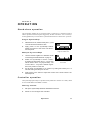
SynchroZap QX250
P/N 35000025
User Manual
© 1998, 1999 Martin Professional A/S, Denmark.
All rights reserved. No part of this manual may be
reproduced, in any form or by any means, without
permission in writing from Martin Professional A/S,
Denmark.
Printed in Denmark.
P/N 35000025, Rev. B
section 1
INTRODUCTION
Thank you for selecting the Martin SynchroZap QX250. This manual covers the SynchroZap QX250 with CPU software version 1.1. For the latest product news and documentation,
please contact your dealer or the Martin web site at http://www.martin.dk.
SynchroZap QX250 safety information
WARNING!
This product is for professional use only. It is not for
household use.
This product presents risks of lethal or severe injury due to fire and heat, electric shock,
ultraviolet radiation, lamp explosion, and falls. Read this manual before powering or
installing the fixture, follow the safety precautions listed below and observe all warnings in
this manual and printed on the fixture. If you have questions about how to operate the fixture safely, please contact your Martin dealer or call the Martin 24-hour service hotline at
+45 70 200 201.
To p r o t e c t y o u r s e l f a n d o t h e r s f r o m e l e c t r i c s h o c k
• Disconnect the fixture from AC power before removing or installing the lamp, fuses, or
any part, and when not in use.
• Always ground (earth) the fixture electrically.
• Use only a source of AC power that complies with local building and electrical codes
and has both overload and ground-fault protection.
• Do not expose the fixture to rain or moisture.
• Refer service to a qualified technician. There are no user-serviceable parts inside.
To p r o t e c t y o u r s e l f a n d o t h e r s f r o m U V r a d i a t i o n a n d
lamp explosion
• Never operate the fixture with missing or damaged lenses and/or covers.
• When replacing the lamp, allow the fixture to cool for at least 5 minutes before opening
the fixture or removing the lamp. Protect your hands and eyes with gloves and safety
glasses.
• Do not stare directly into the light. Never look at an exposed lamp while it is lit.
• Replace the lamp if it becomes defective or worn out.
I ntr od ucti on
3
To p r o t e c t y o u r s e l f a n d o t h e r s f r o m b u r n s a n d f i r e
• Never attempt to bypass the thermostatic switch or fuses. Always replace defective fuses
with ones of the specified type and rating.
• Keep all combustible materials (for example fabric, wood, paper) at least 0.1 meters (4
inches) away from the fixture. Keep flammable materials well away from the fixture.
• Do not illuminate surfaces within 0.3 meters (12 inches) of the fixture.
• Provide a minimum clearance of 0.1 meters (4 inches) around fans and air vents.
• Never place filters or other materials over the lens.
• The exterior of the fixture can reach temperatures up to 65° C (150° F). Allow the fixture
to cool for at least 5 minutes before handling.
• Do not modify the fixture or install other than genuine Martin parts.
• Do not operate the fixture if the ambient temperature (Ta) exceeds 40° C (104° F).
To p r o t e c t y o u r s e l f a n d o t h e r s f r o m i n j u r y d u e t o
falls
• When suspending the fixture above ground level, verify that the structure can hold at
least 10 times the weight of all installed devices.
• Verify that all external covers and rigging hardware are securely fastened and use an
approved means of secondary attachment such as a safety cable.
• Block access below the work area whenever installing or removing the fixture.
4
S ynch ro Zap QX 250
section 2
SETUP
This section describes the steps required to prepare the SynchroZap for operation.
bracket
DIP switch
data output
tilt lock (2)
data input
S/N label
lamp adjustment
screw (3)
mains input
lamp assembly
fuse holder
access plate
screw (2)
Figure 1: Rear view
Unpacking
The SynchroZap QX250 comes with:
• 5-meter, 3-pin shielded XLR control cable
• 1.5-meter, 3-wire IEC power cable
• user manual
The packing material is carefully designed to protect the fixture during shipment - always
use it to transport the fixture.
Installing or changing the lamp
The SynchroZap QX250 is designed to use the Philips MSD-200 or MSD-250/2 discharge
lamp. Installing other lamps may damage the fixture.
For maximum light output, use the MSD-250/2 lamp.
S etup
5
WA R N I N G !
Disconnect the fixture from AC power before proceeding.
The lamp operates under high temperature and pressure
and can explode when hot. Always allow a hot lamp to cool
for at least 5 minutes before removing it from the fixture
and wear safety goggles to protect your eyes.
1.
Remove the 2 lamp access screws from the lamp
assembly and gently remove the assembly. See
Figure 1.
2.
Remove the old lamp, if any, by its ceramic base.
3.
Holding the new lamp by its ceramic base (do
not touch the glass), align the pins as shown in
Figure 2 so that the small pin goes in the small
hole. Insert the lamp firmly and squarely into the
socket and ensure that all 4 small projections on
the ceramic base touch the face of the socket.
4.
Clean the glass bulb with the cloth supplied with
the lamp, particularly if your fingers touch the
glass. A clean, lint-free cloth wetted with alcohol
may also be used.
5.
Turn the lamp assembly so the wires are at the top.
Gently insert the assembly, making sure the lamp
fits through the opening in the reflector. Replace
the lamp access screws.
6.
Figure 2
The lamp holder is pre-adjusted at the factory; however, precise alignment to compensate for slight variations between lamps may improve
performance. See “Adjusting the lamp” on page 14.
Po w e r i n g t h e f i x t u r e
WARNING!
The fixture must be grounded (earthed).
The voltage and frequency settings must match the local
AC power supply.
6
S ynch ro Zap QX 250
Ch e ck vol tag e a nd fre qu en cy s e tti ng s
Verify that the settings printed on the S/N label match your local power supply. If the voltage is not within 5 percent of the local supply, or if the frequency (50/60 Hz) is different,
then the ballast and/or transformer must be rewired by a qualified technician before power
is applied. Please contact your Martin dealer.
Prepare the power cable
The SynchroZap QX250 has a 3-pin IEC power inlet. To use the supplied power cable, you
must install a grounding-type cord cap that fits your supply. Following the manufacturer’s
instructions, connect the yellow/green wire to the ground (earth) pin, the blue wire to the
neutral pin, and the brown wire to the live pin. The table shows some pin identification
schemes; if the pins are not clearly identified, or if you have any doubts about proper installation, consult a qualified electrician.
Connections
Possible Markings
Wire
Pin
Typical
US
UK
brown
live
“L”
yellow or
brass
red
blue
neutral
“N”
silver
black
yellow/green
ground
green
green
Apply power
Note: Do not power the SynchroZap on a variable dimmer circuit. Disconnect the fixture
from power when not in use.
1.
Check the voltage and frequency settings.
2.
Verify that the supply cable is undamaged and rated for the current
requirements of all connected devices.
3.
When ready to operate, plug the prepared power cord into the mains
input on the rear panel and the AC power supply.
Rigging
WA R N I N G !
Always use an approved safety cable.
The SynchroZap may be installed by fastening the mounting bracket directly to a structural
support or by using a rigging clamp. See page 22 for clamps available from Martin.
S etup
7
1.
Verify that the structure can support at least 10 times the weight of all installed
fixtures, clamps, cables, auxiliary equipment, etc.
2.
If hanging the fixture with a rigging clamp, verify that the clamp is undamaged and is designed for the fixture’s weight. Bolt the clamp securely to
the bracket with a grade 8.8 (minimum) M12 bolt and lock nut, or as recommended by the clamp manufacturer, through the clamp hole in the
mounting bracket.
3.
If permanently installing the fixture, verify that the hardware (not
included) and mounting surface can bear at least 10 times the fixture’s
weight. The four 6 mm holes and/or the 13 mm clamp hole in the mounting bracket may be used for attachment.
4.
Working from a stable platform, clamp or fasten the fixture to the structure.
5.
Install a safety cable that can hold at least 10 times the weight of the fixture through/over the support and mounting bracket.
6.
Loosen the tilt locks, tilt the fixture to the desired angle, and retighten.
7.
Verify that the fixture is at least 0.3 meters (12 in.) from the surface to be
illuminated and at least 0.1 meters (4 in.) from any combustible materials.
Verify that the clearance around the air vents is at least 0.1 meters (4 in.).
Connecting the serial data link
The SynchroZap must be connected by a serial data link if it is to be operated by a controller or in stand-alone master/slave mode. The pin-out of the 3-pin data input and output
sockets is compatible with the DMX-512 standard, i.e., pin 1 to shield, pin 2 to cold (-)
and pin 3 to hot (+). As some devices have 5-pin connectors or 3-pin connectors with
reversed polarity on pins 2 and 3, the following adaptor cables may be required.
5-pin to 3-pin
Adaptor
3-pin to 3-pin
Phase-Reversing
Adaptor
Male
Female
Male
Female
Male
Female
1
2
3
4
5
1
2
3
1
2
3
1
2
3
4
5
1
2
3
1
2
3
P/N 11820005
8
3-pin to 5-pin
Adaptor
P/N 11820004
S ynch ro Zap QX 250
P/N 11820006
1.
Connect controller: For a DMX controller with 5-pin output, use a cable with a
5-pin male and a 3-pin female connector, such as P/N 11820005. Pins 4 and 5
are not used. For a DMX controller with 3-pin output, use a cable with 3-pin
male and female connectors such as the one supplied. Connect the cable to
the controller’s DMX output and the SynchroZap’s data input.
2.
Connect additional fixtures: Connect the output of the fixture closest to
the controller to the input of the next fixture. When connecting a SynchroZap QX250 to a Martin fixture with pin 3 cold (-), use a 3-pin phasereversing adaptor such as Martin P/N 11820006.
3.
Terminate the link: Insert a male 120 Ω XLR termination plug in the output of the last fixture on the link. The termination plug, which is simply a
male XLR connector with a 120 Ω, 0.25 watt resistor soldered between
pins 2 and 3, “soaks up” the control signal so it does not reflect back
down the link and cause interference. If linking many SynchroZaps for
stand-alone master/slave operation, it may be necessary to terminate the
input of the first fixture with a female 120 Ω XLR termination plug.
Tips for building a trouble-free serial link
• Use shielded twisted-pair cable designed for RS-485 devices. Though standard microphone cable may work in some situations, it is prone to interference that can cause
unpredictable performance.
• Never use a “Y” connector to split the link. To split the serial link into branches use a
splitter such as the Martin 4-Channel Opto-Isolated RS-485 Splitter/Amplifier. If a splitter is used, terminate each branch of the link.
• Do not overload the link. Up to 32 devices may be connected on a serial link.
Address and mode setting
Select DMX mode
The SynchroZap QX250 has 2 DMX modes: a 6-channel mode that provides full control of
all effects and a 1-channel mode in which the SynchroZap performs a random sequence at 3
trigger rates.
1.
To select the 6-channel mode, simply set an address as described below.
2.
To select the 1-channel mode, set DIP-switch pins 9 and 10 to ON. Pins 1
through 8 are used to select an address between 1 and 255.
Select the address
When operating the SynchroZap QX250 with a controller, the DIP-switch must be set to the
start channel, also known as the address, which is the first channel the controller uses to
send instructions to the fixture. The address may be any channel up to 507 in 6-channel
DMX mode and any channel up to 255 in the 1-channel mode.
S etup
9
For independent control, each fixture must have its own address as in example 1. If independent control is not required, 2 or more SynchroZaps may share the same address: they
will receive the same instructions and behave identically. In example 2, units 1 and 2 will
behave the same, as will units 3 and 4.
1
2
3
4
5
6
7
8
9
10
11
12
13
14
15
16
17
18
19
20
21
22
23
24
Example 1: 4 units, 6-channel control
unit 1
address = 1
unit 2
address = 7
unit 3
address = 13
unit 4
address = 19
units 1 and 2
address = 1
1.
units 3 and 4
address = 7
unit 5
unit 6
unit 7
unit 8
1
2
3
4
5
6
7
8
9
10
11
12
13
14
15
16
17
18
19
20
21
22
23
24
Example 2: 2 sets of 2 units with 6-channel control and
4 units with 1-channel control
Look up the DIP-switch setting for the selected address on page 23. You can
also find the setting by subtracting pin values, shown below, until the total of
the values equals the address. Start with the highest pin value that can be
subtracted and continue until there is no remainder.
3
4
5
6
7
value
1
2
4
8
16
32
64
8
9
10
special
2
256
1
128
pin
DIP-switch pin values
2.
Set the DIP-switch by flipping the OFF pins up and the ON pins down with
a small screwdriver or similar tool.
Example: channel 100
1-channel mode
Pins 3, 6, 7, 9, 10 ON
Example: Channel 50,
6-channel mode
Pins 2, 5 and 6 ON
channel
- value of pin 7
100
- 64
channel
- value of pin 6
50
- 32
remainder
- value of pin 6
36
- 32
remainder
- value of pin 5
18
- 16
remainder
- value of pin 3
4
-4
remainder
- value of pin 2
2
-2
remainder
0
On
On
1 2 3 4 5 6 7 8 9 10
10
remainder
S ynch ro Zap QX 250
1 2 3 4 5 6 7 8 9 10
0
section 3
OPERATION
Stand-alone operation
The SynchroZap QX250 may be operated without a controller in a stand-alone mode in
which it performs a random sequence triggered by the beat of the music. Two or more SynchroZap QX250s may be connected for synchronized stand-alone “master/slave” operation.
Single SynchroZap
With the fixture off, set DIP-switch pins 1,2, and
10 to ON and set the others to OFF.
2.
Apply power to the SynchroZap QX250.
Adjust the volume of the music until the fixture responds.
On
1.
1 2 3 4 5 6 7 8 9 10
Stand-alone setting for
single or master unit
Multiple SynchroZaps
Link the fixtures together as described under
“Connecting the serial data link” on page 8.
2.
Select one SynchroZap to be the “master”
by setting its DIP-switch pins 1, 2, and 10 to
ON as shown above. Any SynchroZap - but
no more than 1 - may be the master regardless of its position on the link.
3.
Set all other SynchroZaps to be “slaves” by setting DIP-switch pin 1 to
ON and setting all other pins to OFF.
4.
Apply power to the fixtures. Adjust the volume of the music until the fixtures respond.
On
1.
1 2 3 4 5 6 7 8 9 10
Stand-alone setting for
slave units
Controller operation
The SynchroZap QX250 may be operated with any DMX-512 controller. It is ideally suited
for use with the Martin 2518 DMX Controller.
Getting started
1.
Set up the SynchroZap QX250 as described in section 2.
2.
Switch on and configure the controller.
Oper at ion
11
3.
Apply power to the SynchroZap. After it resets it is ready to respond to
the controller. The DMX protocol beginning on page 18 describes in
detail how the fixture responds to DMX commands.
Loss of DMX
If the DMX signal is lost, the SynchroZap automatically executes a random sequence using
the music trigger after 5 seconds. DMX control resumes when the signal returns.
Controllable effects
C h a n n e l 1 : l a m p o n / o f f , s h u t t e r, r e s e t
When power is applied to the SynchroZap, the lamp remains off until a “lamp on”
command is sent from the controller. To strike (turn on) the lamp, set channel 1 to lamp
on (5%).
Note: A peak of electric current that can be many times the operating current is drawn when
striking the lamp. Striking many lamps at the same time may cause a voltage drop large
enough to prevent lamps from striking or trip the main circuit breaker. It is a good practice
to strike lamps one at a time at 5 second intervals.
The lamp can be turned off from the controller by sending a “lamp off”
command. Set channel 1 to lamp off (100%), channel 2 to green (45%),
channel 3 to gobo 9 (34%) and hold for 5 seconds.
The lamp cannot be turned on again until after it has cooled for approximately 5 minutes. If the lamp does not strike, send the lamp off command and allow it to cool.
Gobo 9
Channel 1 also controls the shutter, allowing you to black out the light and flash the light at
variable or random speeds for strobe-like effects.
Finally, the mechanical effects can be reset to their home position by sending the “reset”
command (95%).
Channel 2: color wheel
The SynchroZap has 9 dichroic color filters plus an open white position. Between each
position is a split-color position. The color wheel can also be rotated at varying speeds and
scrolled using the music trigger.
Channel 3: gobo wheel
The SynchroZap QX250 has 19 gobos plus an open position. The gobo wheel can be rotated
at varying speeds and scrolled using the music trigger.
12
S ynch ro Zap QX 250
Channels 4 and 5: mirror drums
The SynchroZap has 2 asymmetrically mounted mirror drums with independently controllable rotation. Each drum can rotate in both directions at varying speeds, stand still, or be set
for musically triggered random or synchronized action. Channel 4 controls the left drum
and channel 5 controls the right drum.
Ch annel 6: Syn ch roniz ed dru m rotat io n an d mu sic
trigger speed
Synchronized drum rotation: Synchronized drum rotation causes the mirror drums to
rotate in opposite directions at the same speed with their “tilt” angle offset by 0°, 90°, 180°,
or 270°. This effect can be seen clearly by setting channel 1 to open (10%), channel 2 to
yellow/magenta (25%), channel 3 to gobo 19 (68%), channel 4 to fast ccw rotation (35%),
and then experimenting with the values between 8% and 38% on channel 6.
When synchronized rotation is selected, the drum speed and direction are set on channel 4
and channel 5 has no effect. To regain independent control of the drums, turn synchronized
rotation off (0%) or select a music trigger speed.
If both drum channels are set to music trigger (100%), independent random rotation may be
selected by setting a music trigger speed; synchronized random rotation may be selected by
setting a synchronized drum rotation angle.
Music trigger speed: Channel 6 also controls the effects speed when music trigger is
selected. Three speeds are available. The difference is most noticeable on the mirror drums.
Music trigger works even if no speed is selected, that is, if channel 6 is set to synchronized
rotation.
Oper at ion
13
section 4
BASIC SERVICE
Replacing the lamp
WARNING
The lamp operates under high temperature and pressure
and can explode. Always wear safety goggles to protect
your eyes and allow a hot lamp to cool for at least
5 minutes before removing it from the fixture.
Discharge lamps become more difficult to strike with age. If the lamp is difficult to strike, it
probably needs to be replaced. You can expect, on average, to get 2000 hours of use from
MSD lamps. Please refer to “Installing or changing the lamp” on page 5 for the lamp
replacement procedure.
Adjusting the lamp
The SynchroZap QX250 lamp assembly is adjusted at the factory. Due to differences
between lamps, however, fine adjustment may be improve performance.
1.
Disconnect the fixture from AC
power.
2.
(Optional) Perform a rough
adjustment: Remove the
lamp assembly and turn the
3 lamp adjustment screws
until there are 19 mm (0.75
in) between the 2 plates as
shown. Replace the lamp
assembly.
3.
With controller: Turn on the
SynchroZap
QX250
and
select white light with the
open gobo.
Figure 3: Preliminary adjustment
Without controller: Flip DIP-switch pins 8 and 10 on. Flip all other pins
off. Apply power to the SynchroZap QX250. After it has reset, the fixture
produces a white light with an open gobo for adjustment purposes.
14
S ynch ro Zap QX 250
4.
Wait for the lamp to reach full brightness. Position the fixture so the light
shines on a flat, white surface.
5.
If there is an off-center “hot spot,” the lamp is not centered in the reflector. Pull the hot spot into the center of the field with small adjustments of
one or more of the lamp-adjustment screws.
6.
If the light is significantly brighter in the center of the field than it is at the
edge, the lamp is too far forward in the reflector. Pull the lamp in by turning all three screws clockwise 1/4-turn at a time until the light is evenly
distributed.
7.
If the light is brighter around the edge than it is in the center, or if light
output is low, the lamp is too far back in the reflector. “Push” the lamp out
by turning the screws counterclockwise 1/4-turn at a time until the light is
bright and evenly distributed.
Replacing the main fuse
The holder for the main fuse is built in to the mains input socket. If the fuse blows repeatedly, refer the fixture for servicing by a qualified technician. Never replace the fuse with
one of a different rating!
1.
Unplug the mains cable from the input socket.
2.
Pry open the fuse holder and remove the fuse.
3.
Replace the fuse with one of the same type and rating. The fuse rating is
listed on serial number label on the end plate.
4.
Close the fuse holder and replace the mains cable.
Information for ser vice technicians
WARNING!
There are no user-serviceable parts inside. The following
procedures and all other service shall be performed by
qualified service technicians only.
Basi c S erv ice
15
Ad j us ti ng E U m od e l vol tag e se tt in gs
Local AC Supply
Transformer
Ballast
Freq.
Voltage
Setting
Terminal
Setting
Terminal
50 Hz
220 - 235 V
225 V
3
230 V
230
50 Hz
235 - 245 V
240 V
4
240 V
240
50 Hz
245 - 260 V
240 V
4
250 V
250
Transformer
Ballast
225 V
240 V
230 V
240 V
250 V
Figure 4: EU model transformer and ballast taps
16
1.
Disconnect the fixture from AC power and place it upside down on a work
table. If the lamp is hot, allow it to cool for 5 minutes and wear safety goggles
to protect your eyes.
2.
Remove the screws from the 4 corners of the bottom plate and lift it off.
3.
On the transformer, move the BROWN wire to the transformer terminal
shown in the table above for the local AC supply voltage. The terminals
are indicated on a label on the side of the transformer.
4.
On the ballast, move the BROWN wire to the terminal listed for the voltage. The terminals are indicated on the side of the ballast.
5.
Replace the cover.
S ynch ro Zap QX 250
Ad j us ti ng U S m od e l vol tag e se tt in gs
Local AC Voltage
Transformer Setting
95 - 105 V
100 V, 50/60 Hz
105 - 115 V
110 V, 50/60 Hz
115 - 125 V
120 V, 50/60 Hz
215 - 235 V
225 V, 50/60 Hz
Ballast
Transformer
225 V
120 V
110 V
100 V
225 V / 60 Hz
225 V / 50 Hz
Figure 5: US model transformer and ballast taps
1.
Disconnect the fixture from AC power and place it upside down on a work
table. If the lamp is hot, allow it to cool for 5 minutes and wear safety goggles
to protect your eyes.
2.
Remove the screws from the 4 corners of the bottom plate and lift it off.
3.
On the ballast, move the BROWN wire to the 225 V / 50 Hz terminal for
50 Hz AC or to the 225 V / 60 Hz terminal for 60 Hz AC.
4.
On the transformer, move the BROWN wire to the setting as listed above
for the local AC voltage.
5.
Replace the cover.
Basi c S erv ice
17
appendix a
DMX 512 PROTOCOL
6-chan nel DMX protocol
Channel
1
2
18
DMX Values
Percent
0 - 10
11 - 19
20 - 39
40 - 100
101 - 109
110 - 130
131 - 180
181 - 239
240 - 248
249 - 255
0-3
4-7
8 - 15
16 - 39
40 - 43
44 - 51
52 - 71
72 - 94
95 - 97
98 - 100
0-8
9 - 17
18 - 26
27 - 35
36 - 44
45 - 53
54 - 62
63 - 71
72 - 80
81 - 89
90 - 98
99 - 107
108 - 116
117 - 125
126 - 134
135 - 143
144 - 152
153 - 161
162 - 170
171 - 179
180 - 187
188 - 237
238 - 248
249 - 255
0-3
4-7
8 - 10
11 - 14
15 - 17
18 - 21
22 - 24
25 - 28
29 - 31
32 - 35
36 - 38
39 - 42
43 - 45
46 - 49
50 - 53
54 - 56
57 - 60
61 - 63
64 - 67
68 - 70
71 - 73
74 - 93
94 - 97
98 - 100
Effect
Shutter, lamp power, reset
Blackout (shutter closed)
Lamp power on, shutter open
Shutter open
Strobe, fast Æ slow
Blackout
Random strobe
Random strobe w/music trigger
Blackout
Reset
Lamp power off (Set color to green, gobo to
position 9 and hold 5 seconds.)
Colors
White
White/pink
Pink
Pink/light green
Light green
Light green/yellow
Yellow
Yellow/magenta
Magenta
Magenta/light blue
Light blue
Light blue/green
Green
Green/orange
Orange
Orange/blue
Blue
Blue/deep orange
Deep orange
Deep orange/white
White
Continuous rotation, slow Æ fast
White
Music trigger
S ynch ro Zap QX 250
Channel
3
4
5
6
DMX Values
Percent
Effect
0-8
9 - 17
18 - 26
27 - 35
36 - 44
45 - 53
54 - 62
63 - 71
72 - 80
81 - 89
90 - 98
99 - 107
108 - 116
117 - 125
126 - 134
135 - 143
144 - 152
153 - 161
162 - 170
171 - 179
180 - 187
188 - 237
238 - 248
249 - 255
0-3
4-7
8 - 10
11 - 14
15 - 17
18 - 21
22 - 24
25 - 28
29 - 31
32 - 35
36 - 38
39 - 42
43 - 45
46 - 49
50 - 53
54 - 56
57 - 60
61 - 63
64 - 67
68 - 70
71 - 73
74 - 93
94 - 97
98 - 100
Gobos
Open
Gobo 1
Gobo 2
Gobo 3
Gobo 4
Gobo 5
Gobo 6
Gobo 7
Gobo 8
Gobo 9
Gobo 10
Gobo 11
Gobo 12
Gobo 13
Gobo 14
Gobo 15
Gobo 16
Gobo 17
Gobo 18
Gobo 19
Open
Continuous rotation, slow Æ fast
Open
Music trigger
0-2
3 - 89
90 - 176
177 - 209
210 - 255
0-1
2 - 35
36 - 69
70 - 82
83 - 100
Mirror drum 1 & synchronized rotation
No rotation
Continuous ccw rotation, slow Æ fast
Continuous cw rotation, fast Æ slow
No rotation
Music trigger, drum 1
0-2
3 - 89
90 - 176
177 - 209
210 - 255
0-1
2 - 35
36 - 69
70 - 82
83 - 100
Mirror drum 2
No rotation
Continuous ccw rotation, slow Æ fast
Continuous cw rotation, fast Æ slow
No rotation
Music trigger, drum 2
0 - 19
20 - 39
40 - 59
60 - 79
80 - 99
0-7
8 - 15
16 - 23
24 - 31
32 - 39
Synchronized rotation
Off
0° offset
90° offset
180° offset
270° offset
100 - 194
195 - 224
225 - 255
40 - 76
77 - 88
89 - 100
Music trigger speed
Slow
Medium
Fast
D MX 512 P r oto col
19
1-chan nel DMX protocol
Channel
1
20
DMX Values
0 - 50
51 - 101
102 - 152
153 - 255
Percent
0 - 19
20 - 39
40 - 59
60 - 100
Effect
Random sequence
Blackout
2.0 second trigger
1.0 second trigger
0.2 second trigger
S ynch ro Zap QX 250
appendix b
SPECIFICATIONS
Measurements
•
•
Dimensions w/o bracket (LxWxH): ........... 372 x 405 x 190 mm (14.6 x 15.9 x 7.5 in)
Weight with bracket but no clamp: ..........................................................11.4 kg (25 lb)
Electrical, EU model
•
•
•
•
•
Power, current consumption at 230 V, 50 Hz with MSD 250/2: ............. 300 W, 1.51 A
Power factor at 230 V, 50 Hz with MSD 250/2 ....................................................... 0.87
Ballast taps:...................................................................... 230 V / 240 V / 250 V, 50 Hz
Main fuse ............................................................ 3.15 A T (time delay), P/N 05020013
Circuit board fuse .................................................... 2 A T (time delay), P/N 05020009
Electrical, US model
•
•
•
•
•
•
•
Power, current consumption at 100 V, 50 Hz with MSD 250/2: .................. 280 W, 3 A
Power factor at 100 V, 50 Hz with MSD 250/2 ....................................................... 0.92
Power, current consumption at 120 V, 60 Hz with MSD 250/2: ............... 280 W, 2.7 A
Power factor at 120 V, 60 Hz with MSD 250/2 ....................................................... 0.86
Transformer taps:........................................... 100 V / 110 V / 120 V / 225 V, 50/60 Hz
Main fuse .............................................................. 6.3 A T (time delay), P/N 05020020
Circuit board fuse .................................................... 2 A T (time delay), P/N 05020009
Philips MSD 250/2 lamp
•
•
•
•
Power ............................................................................................................... 250 watts
Rated life....................................................................................................... 2000 hours
Color temperature ................................................................................................ 5600K
Martin part number.................................................................................. P/N 97010100
Philips MSD 200 lamp
•
•
•
•
Power ............................................................................................................... 200 watts
Rated life....................................................................................................... 2000 hours
Color temperature ................................................................................................ 5600K
Martin part number.................................................................................. P/N 97010106
Communication
•
•
•
Electrical standard .............................................................................................. RS-485
Protocol.................................................................................... USITT DMX512 (1990)
I/O sockets ........................... 3-pin XLR male/female, pin 1=shield, pin 2 (-), pin 3 (+)
S peci fi cati ons
21
Construction
•
•
Housing............................................................................................ aluminum and steel
Finish ................................................................................. electrostatic powder coating
Thermal
•
Maximum ambient temperature (Ta) .......................................................40° C (104° F)
•
Surface temperature under normal operating conditions.........................65° C (150° F)
Accessories
•
•
Half-coupler clamp .................................................................................. P/N 91602005
G clamp.................................................................................................... P/N 91602003
Service DIP-switch settings
•
•
•
22
Lamp adjust ..............................................................................................pins 8, 10 ON
Lamp off ...................................................................................................pins 7, 10 ON
LED chase, auto trigger ............................................................................pins 4, 10 ON
S ynch ro Zap QX 250
appendix c
D I P - S W I T C H TA B L E
This table shows DIP-switch settings for channels 1- 511. Note: Pin 10 is always OFF in the
6-channel DMX mode. Pins 9 and 10 must be switched ON to select the 1-channel DMX
mode. In this mode, pins 1 - 8 are used to select any channel up to 255.
To find a setting, locate the channel in the table. Follow the row to the left to find the settings for pins 1 through 5; follow the column to the top to find the settings for pins 6
through 9. A “0” indicates the pin is turned off and a “1” indicates the pin is turned on.
',306ZLWFK#6HWWLQJ
&4
3
4
3
4
3
4
3
4
3
4
3
4
3
4
3
4
3
4
3
4
3
4
3
4
3
4
3
4
3
4
3
4
3# #2))
4# #21
&5 &6 &7
3 3 3
3 3 3
4 3 3
4 3 3
3 4 3
3 4 3
4 4 3
4 4 3
3 3 4
3 3 4
4 3 4
4 3 4
3 4 4
3 4 4
4 4 4
4 4 4
3 3 3
3 3 3
4 3 3
4 3 3
3 4 3
3 4 3
4 4 3
4 4 3
3 3 4
3 3 4
4 3 4
4 3 4
3 4 4
3 4 4
4 4 4
4 4 4
&8
3
3
3
3
3
3
3
3
3
3
3
3
3
3
3
3
4
4
4
4
4
4
4
4
4
4
4
4
4
4
4
4
&<
&;
&:
&9
3
3
3
3
3
3
3
4
3
3
4
3
3
3
4
4
3
4
3
3
3
4
3
4
3
4
4
3
3
4
4
4
4
3
3
3
4
3
3
4
4
3
4
3
4
3
4
4
4
4
3
3
4
4
3
4
4
4
4
3
4
4
4
4
4
5
6
7
8
9
:
;
<
43
44
45
46
47
48
49
4:
4;
4<
53
54
55
56
57
58
59
5:
5;
5<
63
64
65
66
67
68
69
6:
6;
6<
73
74
75
76
77
78
79
7:
7;
7<
83
84
85
86
87
88
89
8:
8;
8<
93
94
95
96
97
98
99
9:
9;
9<
:3
:4
:5
:6
:7
:8
:9
::
:;
:<
;3
;4
;5
;6
;7
;8
;9
;:
;;
;<
<3
<4
<5
<6
<7
<8
<9
<:
<;
<<
433
434
435
436
437
438
439
43:
43;
43<
443
444
445
446
447
448
449
44:
44;
44<
453
454
455
456
457
458
459
45:
45;
45<
463
464
465
466
467
468
469
46:
46;
46<
473
474
475
476
477
478
479
47:
47;
47<
483
484
485
486
487
488
489
48:
48;
48<
493
494
495
496
497
498
499
49:
49;
49<
4:3
4:4
4:5
4:6
4:7
4:8
4:9
4::
4:;
4:<
4;3
4;4
4;5
4;6
4;7
4;8
4;9
4;:
4;;
4;<
4<3
4<4
4<5
4<6
4<7
4<8
4<9
4<:
4<;
4<<
533
534
535
536
537
538
539
53:
53;
53<
543
544
545
546
547
548
549
54:
54;
54<
553
554
555
556
557
558
559
55:
55;
55<
563
564
565
566
567
568
569
56:
56;
56<
573
574
575
576
577
578
579
57:
57;
57<
583
584
585
586
587
588
589
58:
58;
58<
593
594
595
596
597
598
599
59:
59;
59<
5:3
5:4
5:5
5:6
5:7
5:8
5:9
5::
5:;
5:<
5;3
5;4
5;5
5;6
5;7
5;8
5;9
5;:
5;;
5;<
5<3
5<4
5<5
5<6
5<7
5<8
5<9
5<:
5<;
5<<
633
634
635
636
637
638
639
63:
63;
63<
643
644
645
646
647
648
649
64:
64;
64<
653
654
655
656
657
658
659
65:
65;
65<
663
664
665
666
667
668
669
66:
66;
66<
673
674
675
676
677
678
679
67:
67;
67<
683
684
685
686
687
688
689
68:
68;
68<
693
694
695
696
697
698
699
69:
69;
69<
6:3
6:4
6:5
6:6
6:7
6:8
6:9
6::
6:;
6:<
6;3
6;4
6;5
6;6
6;7
6;8
6;9
6;:
6;;
6;<
6<3
6<4
6<5
6<6
6<7
6<8
6<9
6<:
6<;
6<<
733
734
735
736
737
738
739
73:
73;
73<
743
744
745
746
747
748
749
74:
74;
74<
753
754
755
756
757
758
759
75:
75;
75<
763
764
765
766
767
768
769
76:
76;
76<
773
774
775
776
777
778
779
77:
77;
77<
783
784
785
786
787
788
789
78:
78;
78<
793
794
795
796
797
798
799
79:
79;
79<
7:3
7:4
7:5
7:6
7:7
7:8
7:9
7::
7:;
7:<
7;3
7;4
7;5
7;6
7;7
7;8
7;9
7;:
7;;
7;<
7<3
7<4
7<5
7<6
7<7
7<8
7<9
7<:
7<;
7<<
833
834
835
836
837
838
839
83:
83;
83<
843
844
D IP- Sw it ch Tabl e
23
SynchroZap QX250 6-Channel DMX Protocol
&K1#
58
%22
#4
83
#5 ZKLWH
OLJKW#
JUHHQ
58
#7
6
7
2
3
#8
6
7
2
3
*#4
*#5
43
\HOORZ
*#7
*#8
73
PDJH
QWD
OLJKW#
EOXH
:8
*#9
*#:
53
*#;
433
*#<
58
83
RII
63
83
533
93
EOXH
458
:3
GHHS#
RUDQJH
483
73
83
:8
433
4:8
533
63
:8
73
558
4:8
93
07
<3
558
583
PXVLF#WULJJHU
;3
<3
0XVLF#WULJJHU#VSHHG#
5:3ƒ#RIIVHW
VORZ
433
458
483
PHGLXP
4:8
533
IDVW
558
583
-#6HW#FK1#5#WR#JUHHQ#DQG#FK1#6#WR#JRER#<#WR#HQDEOH#ODPS#RII#
FRPPDQG1#+ROG#IRU#8#VHFRQGV1
← = #YDULDEOH#VSHHG/#SRLQWV#WR#IDVW
Martin Professional A/S
Olof Palmes Allé 18
DK-8200 Aarhus N, Denmark
Phone: +45 8740 0000 Fax: +45 8740 0010
Internet: http://www.martin.dk
583
PXVLF#WULJJHU
533
:3
07
RSHQ
;3
QR#URWDWLRQ
83
ZKLWH
#FRQWLQXRXV#URWDWLRQ
→
:3
FRQWLQXRXV#FZ#URWDWLRQ
←
<3
#FRQWLQXRXV#URWDWLRQ
→
QR#URWDWLRQ
483
583
5HVHW /DPS
2II-
;3
ZKLWH
93
458
558
%ODFNRXW
FRQWLQXRXV#FZ#URWDWLRQ
←
6\QFKURQL]HG#URWDWLRQ
3ƒ#RIIVHW
<3ƒ#RIIVHW
4;3ƒ#RIIVHW
58
RUDQJH
4:8
*#43 *#44 *#45 *#46 *#47 *#48 *#49 *#4: *#4; *#4< RSHQ
FRQWLQXRXV#FFZ#URWDWLRQ
→
53
483
5DQGRP#VWUREH
Z2PXVLF#WULJJHU
83
JUHHQ
FRQWLQXRXV#FFZ#URWDWLRQ
→
43
#9
63
83
*#6
458
#%22 5DQGRP#VWUREH
←
53
SLQN
433
#6WUREH
43
#6 RSHQ
:8
/DPS# #6KXWWHU#RSHQ
RQ