1
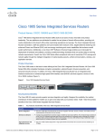
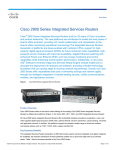
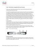
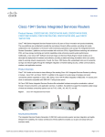
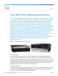
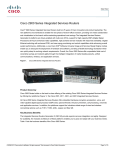
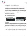
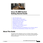
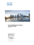
Cisco IE 3010 Switch
Getting Started Guide
•
About this Guide
•
Box Contents
•
Running Express Setup
•
Managing the Switch
•
Installing the Switch
•
Wiring the Power Source
•
Connecting the Switch Ports
•
Troubleshooting
•
Obtaining Documentation and Submitting a Service Request
Cisco IE 3010 Switch Getting Started Guide
78-19582-02
1
Cisco IE 3010 Switch Getting Started Guide
About this Guide
This guide describes how to use Express Setup to initially configure your
Cisco IE 3010 switch. It also covers switch management options, rack-mounting,
wiring procedures, port and module connection procedures, and troubleshooting.
For additional installation and configuration information for the switch, see the
Cisco IE 3010 switch documentation on Cisco.com. For system requirements,
important notes, limitations, open and resolved bugs, and last-minute
documentation updates, see the release notes, also on Cisco.com. For translations
of the warnings that appear in this publication, see the Regulatory Compliance
and Safety Information for the Cisco IE 3010 Switch on the documentation CD.
The product warranty information is on the documentation CD.
When using the online publications, see the documents that match the Cisco IOS
software version running on the switch.
Cisco IE 3010 Switch Getting Started Guide
2
78-19582-02
Cisco IE 3010 Switch Getting Started Guide
Box Contents
3
C isco IE
3010
1
2
10 D
30 n C
IE tio
a
co t
is en
C m
u
oc
D
5
6
7
8
9
208330
4
10
1
Cisco IE 30101 switch
6
Four number-12 Phillips truss-head screws
2
Two 19-inch mounting brackets
7
Six number-8 Phillips flat-head screws
3
Cable guide
8
One black Phillips machine screw
4
Documentation
9
Dual-hole ground lug
5
Four number-8 Phillips machine screws
10 Console cable or USB cable2
1. Cisco IE-3010-24TC shown. Your switch model might look different.
2. Item is orderable.
Note
Verify that you have received these items. If any item is missing or damaged,
contact your Cisco representative or reseller for instructions.
Cisco IE 3010 Switch Getting Started Guide
78-19582-02
3
Cisco IE 3010 Switch Getting Started Guide
Running Express Setup
You should use Express Setup to enter the initial IP information. You can then
access the switch through the IP address for further configuration.
Note
To use the CLI-based initial setup program, see Appendix C, “Configuring the
Switch with the CLI Setup Program,” in the switch hardware guide.
You need this equipment:
Note
PC with Windows 2000, XP, Vista, or Windows Server 2003
•
Web browser (Internet Explorer 6.0, 7.0, or Firefox 1.5, 2.0, or later) with
JavaScript enabled
•
Straight-through or crossover Category 5 or 6 cable
Before running Express Setup, disable any pop-up blockers or proxy settings on
your browser and any wireless client running on your PC.
C isco IE
Step 2
During Express Setup, the switch acts as a DHCP server. If your PC has a static IP address,
temporarily configure your PC settings to use DHCP.
Note
Step 3
3010
208331
Make sure that nothing is connected to the
switch.
Write down the static IP address. You need this address in Step 12.
Connect the wires to the switch power-input
terminal.
See the “Wiring the Power Source” section on
page 16 for instructions about AC- or
DC-power connections.
208332
Step 1
•
Cisco IE 3010 Switch Getting Started Guide
4
78-19582-02
Cisco IE 3010 Switch Getting Started Guide
Step 4
Approximately 45 seconds after the switch powers on, it begins the power-on self-test
(POST), which can take up to 5 minutes.
During POST, the SYSTEM LED blinks green, and the port LEDs turn green.
s
When POST is complete, the SYSTEM LED remains green, and the other LEDs turn off.
Troubleshooting
If the SYSTEM LED blinks green, does not turn green, or turns amber, contact your Cisco
representative or reseller. The switch failed POST.
Step 5
Press the recessed Express Setup button with
a simple tool, such as a paper clip.
You might need to press the button for
3 seconds.
207218
When you press the Express Setup button, a
switch 10/100 Ethernet port LED blinks
green.
Troubleshooting
If a switch port LED does not blink green,
repeat Steps 1 to 5. You can also use the setup
program described in the switch hardware
guide.
Cisco IE 3010 Switch Getting Started Guide
78-19582-02
5
Cisco IE 3010 Switch Getting Started Guide
Connect a Category 5 or 6 cable to the
blinking 10/100 Ethernet port.
Connect the other end of the cable to the
Ethernet port on your PC.
Wait until the port LEDs on the switch and
your PC or laptop are either green or blinking
green. Green LEDs mean a successful
connection.
C isco C
G S 2520
207181
Step 6
Troubleshooting
If the port LEDs are not green after about 30
seconds, make sure that:
•
You connected the Ethernet cable to the
blinking 10/100 Ethernet port (not to an
uplink port such as the dual-purpose
port).
•
You are using a Category 5 or 6 cable and
that the cable is not damaged.
•
The other device is turned on.
You can ping IP address 169.254.0.1 to verify
the connection.
Cisco IE 3010 Switch Getting Started Guide
6
78-19582-02
Cisco IE 3010 Switch Getting Started Guide
Step 7
Start a browser session on the PC, open a well-known website, such as Cisco.com. The switch
prompts you for the default username and password. At the prompt, enter the default
username and password cisco.
The Express Setup window appears.
Troubleshooting
If the Express Setup window does not appear, make sure that any browser pop-up blockers or
proxy settings are disabled and that any wireless client on your PC or laptop is disabled.
Cisco IE 3010 Switch Getting Started Guide
78-19582-02
7
Cisco IE 3010 Switch Getting Started Guide
Step 8
Enter this information in the Network Settings fields:
Note
In the Management Interface (VLAN ID) field, the default is 1.
•
Note
We recommend that you use the default VLAN value. During Express Setup,
VLAN 1 is the only VLAN on the switch. Enter a new VLAN ID only if you want to
change the management interface through which you manage the switch. The VLAN
ID range is 1 to 1001.
•
In the IP Assignment Mode field, we recommend that you use the default, Static, which
means that the switch always has the IP address that you assign. Use the DHCP setting
when you want the switch to automatically obtain an IP address from a DHCP server.
•
In the IP Address field, enter the IP address of the switch.
•
In the Subnet Mask field, click the drop-down arrow, and select a subnet mask.
•
In the Default Gateway field, enter the IP address for the default gateway (router).
•
Enter your password in the Switch Password field. The password can be from 1 to 25
alphanumeric characters, can start with a number, is case sensitive, allows embedded
spaces, but does not allow spaces at the beginning or end. In the Confirm Switch
Password field, enter your password again.
Note
Step 9
All entries must be in English letters.
You must change the password from the default password, cisco.
Enter the Optional Settings now, or enter them later:
You can enter other administrative settings in the Express Setup window. For example, the
optional administrative settings identify and synchronize the switch for enhanced
management. NTP synchronizes the switch clock with the network clock. You can also
manually set the system clock settings.
Click Submit to save your changes.
For more information about the Express Setup fields, see the online help for the Express Setup
window.
Step 10
After you click Submit, these events occur:
•
The switch is configured and leaves Express Setup mode.
•
The browser displays a warning message and tries to connect with the earlier switch IP
address. Typically, connectivity between the PC and the switch is lost because the
configured switch IP address is in a different subnet from the PC IP address.
Cisco IE 3010 Switch Getting Started Guide
8
78-19582-02
Cisco IE 3010 Switch Getting Started Guide
Step 11
Disconnect the switch from the PC, and install the switch in your network. See the “Installing
the Switch” section on page 10.
Step 12
If you changed the static IP address on your PC in Step 2, change it to the previously
configured static IP address.
Step 13
See the “Managing the Switch” section on page 9 for information about configuring and
managing the switch.
Managing the Switch
After completing Express Setup and installing the switch in your network, you
can use the CLI for further configuration. You can enter Cisco IOS commands and
parameters through the CLI. Use one of these options to access the CLI:
•
Switch RJ-45 Console Port
•
Switch USB Console Port
Switch RJ-45 Console Port
1.
Connect the RJ-45-to-DB-9 adapter cable to the 9-pin serial port on the PC.
Connect the other end of the cable to the switch console port.
2.
Start a terminal-emulation program on the PC.
3.
Configure the PC terminal emulation software for 9600 baud, 8 data bits, no
parity, 1 stop bit, and no flow control.
4.
Use the CLI to enter configuration commands. See the software configuration
guide and the command reference for more information.
Switch USB Console Port
If you use the USB console port, you must install the Cisco Windows USB device
driver on the PC that is connected to the USB console port. See the switch
hardware installation guide for installation instructions.
1.
Connect an USB cable to the PC USB port. Connect the other end of the cable
to the mini-B (5-pin-connector) USB console port on the switch.
2.
Start a terminal-emulation program on the PC.
Cisco IE 3010 Switch Getting Started Guide
78-19582-02
9
Cisco IE 3010 Switch Getting Started Guide
3.
Configure the PC terminal emulation software for 9600 baud, 8 data bits, no
parity, 1 stop bit, and no flow control.
4.
Use the CLI to enter configuration commands. See the software configuration
guide and the command reference for more information.
Note
You cannot use the switch RJ-45 console port and the switch USB console
port at the same time to access the CLI.
Installing the Switch
This section covers 19-inch rack-mounting, wiring procedures, and switch port
connections. The illustrations show the Cisco IE-3010-24TC switch. You can
install and connect other Cisco IE 3010 switches as shown in these examples. For
alternate mounting procedures, such as installing the switch on a wall and for
additional cabling information, see the switch hardware installation guide.
Equipment That You Need
•
Ratcheting torque flathead screwdriver that exerts up to 15-inch pound (in-lb)
of torque
•
Ring, spade, or flanged spade terminal (terminals should be insulated):
– Ring terminal (such as Tyco part number 2-34158-1 for 16–14 AWG, or
2-34852-1 for 12–10 AWG wire)
– Spade terminal (such as Tyco part number 54367-2 for 16–14 AWG wire)
– Flanged spade terminal (such as Tyco part number 2-324165-1 for 16–14
AWG wire, or 1-324581-1 for 12–10 AWG wire)
Cisco IE 3010 Switch Getting Started Guide
10
78-19582-02
Cisco IE 3010 Switch Getting Started Guide
For IP-30 compliance:
- Use the 16-14 AWG wire and appropriate terminals for the AC or
high-voltage DC power supply
Note
- Use the 12-10 AWG wire and appropriate terminals for the low-voltage
DC power supply
•
Crimping tool (such as Thomas & Bett part number WT2000, ERG-2001 or
equivalent)
•
6-gauge copper ground wire (such as Belden part number 9902 or equivalent)
•
12-AWG wire (minimum) for the low-voltage power-supply module and
16-AWG wire (minimum) for the high-voltage power-supply module
•
For power source connections, use wires rated for at least 194°F (90°C)
•
UL- and CSA-rated style 1007 or 1569 twisted-pair copper appliance wiring
material (AWM) wire (such as Belden part number 9318)
•
Wire-stripping tools for stripping 6-, 10-, 12-, 14-, and 16-gauge wires.
•
Number-2 Phillips screwdriver for rack-mounting
•
Flat-blade screwdriver
Before You Begin
Before installing the switch, verify that these guidelines are met:
•
Clearance to the cable-side view or the power-supply-side view is such that
the LEDs can be easily read.
•
Cabling is away from sources of electrical noise, such as radios, power lines,
and fluorescent lighting fixtures. Make sure that the cabling is away from
other devices that might damage the cables.
•
Airflow around the switch and through the vents is unrestricted. To prevent
overheating, the switch must meet the minimum clearance of 1.75 inches
(4.4 cm) at the top and bottom.
•
Temperature around the unit does not exceed 140°F (60°C). If the switch is
installed in a closed or multirack assembly, the temperature around it might
be higher than normal room temperature.
Cisco IE 3010 Switch Getting Started Guide
78-19582-02
11
Cisco IE 3010 Switch Getting Started Guide
•
Relative humidity around the switch does not exceed 95 percent
(noncondensing).
•
Altitude at the installation site is not higher than 10,000 feet.
•
For 10/100 and 10/100/1000 fixed ports, cable lengths from the switch to
connected devices are not longer than 328 feet (100 meters).
•
For cable lengths for small form-factor pluggable (SFP)-module connections,
see the hardware installation guide on Cisco.com and the module
documentation.
Installation Warning Statements
This section includes the basic installation warning statements. Translations of
these warning statements appear in the Regulatory Compliance and Safety
Information for the Cisco IE 3010 Switch document that is on the documentation
CD.
Warning
This unit is intended for installation in restricted access areas. A restricted
access area can be accessed only through the use of a special tool, lock and
key, or other means of security. Statement 1017
Warning
Only trained and qualified personnel should be allowed to install, replace, or
service this equipment. Statement 1030
Warning
To prevent the system from overheating, do not operate it in an area that
exceeds the maximum recommended ambient temperature of:
140°F (60°C) Statement 1047
Warning
This equipment is intended to be grounded to comply with emission and
immunity requirements. Ensure that the switch functional ground lug is
connected to earth ground during normal use. Statement 1064
Cisco IE 3010 Switch Getting Started Guide
12
78-19582-02
Cisco IE 3010 Switch Getting Started Guide
Warning
To prevent airflow restriction, allow clearance around the ventilation openings
to be at least: 1.75 in. (4.4 cm) Statement 1076
Attaching the Brackets
Use six Phillips flat-head screws to attach the long side of the brackets to the
switches in one of three mounting positions. For information on mounting ESTI
and 24-inch brackets, see the hardware guide.
C isco IE
3010
1
2
C isco IE
3010
3
2
208333
C isco IE
3010
Sw itch Seri
es
4
Cisco IE 3010 Switch Getting Started Guide
78-19582-02
13
Cisco IE 3010 Switch Getting Started Guide
1
Mid-mounting position
3 Cable-side mounting position
2
Number-8 Phillips flat-head
screws
4 Power-supply-side mounting
position
Rack-Mounting the Switch
Use the four number-12 Phillips machine screws to attach the brackets to the rack.
Use the black Phillips machine screw to attach the cable guide to the left or right
bracket.
Warning
To prevent bodily injury when mounting or servicing this unit in a rack, you must
take special precautions to ensure that the system remains stable. The
following guidelines are provided to ensure your safety:
This unit should be mounted at the bottom of the rack if it is the only unit in the
rack.
When mounting this unit in a partially filled rack, load the rack from the bottom
to the top with the heaviest component at the bottom of the rack.
If the rack is provided with stabilizing devices, install the stabilizers before
mounting or servicing the unit in the rack. Statement 1006
Warning
For mounting railway-application equipment and for EN50155 standard
compliance, the switch must be installed only in a rack mid-mounting position.
If you install the switch in a front rack-mounting (cable side or power supply
side) position or in a wall-mounting position, a mechanical failure can occur
that results in the switch becoming detached from the rack. Statement 403
Cisco IE 3010 Switch Getting Started Guide
14
78-19582-02
Cisco IE 3010 Switch Getting Started Guide
.
1
C isco IE
3010
C isco IE
3010
4
6
3
2
4
208334
C isco IE
3010
Sw itch Seri
es
5
4
1 Mid-mounting position
4 Number-12 Phillips machine
screws
2 Black Phillips machine screw
5 Power-supply-side mounting
position
3 Cable-side mounting position
6 Cable guide
Cisco IE 3010 Switch Getting Started Guide
78-19582-02
15
Cisco IE 3010 Switch Getting Started Guide
Wiring the Power Source
The switches have two power supply slots to support these power supply modules:
•
PWR-RGD-LOW-DC: low-voltage DC (24 to 60 VDC)
•
PWR-RGD-AC-DC: high-voltage AC (100 to 240 VAC) or high-voltage
DC (100 to 250 VDC)
The switch supports these power-supply module combinations:
•
Single low-voltage DC
•
Single high-voltage AC or DC
•
Two high-voltage AC or DC
•
Two low-voltage DC
•
One high-voltage AC or DC and one low-voltage DC
For detailed information on installing the power supply modules and for the
power-supply module specifications, see the hardware installation guide.
Grounding the Switch
Follow these steps to connect the switch to a protective ground.
Warning
This equipment must be grounded. Never defeat the ground conductor or
operate the equipment in the absence of a suitably installed ground conductor.
Contact the appropriate electrical inspection authority or an electrician if you
are uncertain that suitable grounding is available. Statement 1024
Use a standard Phillips screwdriver or a ratcheting torque screwdriver with a Phillips head to
remove the ground screw from the cable-side of the switch. You need the screw in Step 4.
Step 2
Strip the 6-gauge ground wire to 0.5 inch
(12.7 mm) ± 0.02 inch (0.5 mm).
0.5 inch (12.7 mm)
119516
Step 1
Cisco IE 3010 Switch Getting Started Guide
16
78-19582-02
Cisco IE 3010 Switch Getting Started Guide
Insert the ground wire into the terminal lug,
and crimp the terminal to the wire.
Step 4
Slide the ground screw from Step 1 through the terminal lug.
Step 5
Insert the ground screw into the ground-screw
opening on the cable side.
119626
Step 3
3010
208335
Cisco IE
Step 6
Use a ratcheting torque screwdriver to tighten the ground screw to 30 in-lb (± 2 in-lb).
Step 7
Attach the other end of the ground wire to a grounded bare metal surface, such as a ground
bus or a grounded bare rack.
Cisco IE 3010 Switch Getting Started Guide
78-19582-02
17
Cisco IE 3010 Switch Getting Started Guide
Connecting to the Power Source
Prepare the power cable.
Step 1
Warning
This unit might have more than one power supply connection. All connections
must be removed to de-energize the unit. Statement 1028
Warning
This product relies on the building’s installation for short-circuit (overcurrent)
protection. Ensure that the protective device is rated not greater than:
AC: 5 A, DC: 15 A. Statement 1005
Locate the switch power-input terminal.
The terminal screws are labeled on the
power-input terminal cover.
Identify the line and neutral AC-power
terminal screws. The line terminal screw is
labeled L, and the neutral terminal screw is
labeled N.
100-240V~
, 50-60H
z, 2A
5
2A
100-240V~
, 50-60H
z, 2A
5
2A
10A
DC power:
10A
207221
AC power:
Identify the positive and negative DC-power
terminal screws. The positive terminal screw
is labeled +, and the negative terminal screw
is labeled –.
Note
Step 2
The terminal screws for power-supply
module 1 are on the side labeled
PSU1, and the terminal screws for
power-supply module 2 are on the
side labeled PSU2. Make sure that
you connect the wires to the correct
terminal screws.
Locate the AC and DC circuit breakers, turn them OFF, and tape them in the OFF position.
Note
Do not connect the switch to a power source that has an ON/OFF switch.
Cisco IE 3010 Switch Getting Started Guide
18
78-19582-02
Cisco IE 3010 Switch Getting Started Guide
Step 3
Use a Phillips screwdriver to loosen the captive screw on the power-input terminal, and open
the cover.
Step 4
Use twisted-pair copper wire (14- to 18-AWG) long enough to connect from the power-input
terminal to the power source.
Step 5
Step 6
Use 12-AWG (minimum) for the low-voltage DC power supply module, and use
16-AWG (minimum) for the high-voltage AC or DC power supply module.
Strip each of the two wires to 0.25 inch (6.3
mm) ± 0.02 inch (0.5 mm). Do not strip more
than 0.27 inch (6.8 mm) of insulation from
the wire. Stripping more than the
recommended amount of wire can leave
exposed wire from the connector after
installation.
208565
Note
0.27 inch (6.8 mm)
Insert the wire into a spade terminal, and
crimp the spade terminal to the wire.
You can use a ring, spade, or flanged
spade terminal.
207225
Note
Cisco IE 3010 Switch Getting Started Guide
78-19582-02
19
Cisco IE 3010 Switch Getting Started Guide
Step 7
Loosen the terminal screw, and slide the
spade terminal under the screw and washer.
Use the appropriate terminal screws,
depending on whether you are
installing a high-voltage (AC or DC)
or a low-voltage (DC) power supply.
C
Ciisc
sco IEE 300
10
208336
Note
Step 8
AC power:
Insert the line wire into the terminal screw
labeled L and the neutral wire into the
terminal screw labeled N.
Make sure that you cannot see any wire lead.
Only wire with insulation should extend from
the terminal screw.
C
Ciisc
sco IEE 300
10
Cisco IE 3010 Switch Getting Started Guide
20
78-19582-02
Cisco IE 3010 Switch Getting Started Guide
DC power:
Make sure that you cannot see any wire lead.
Only wire with insulation should extend from
the terminal screw.
Note
Cisco IE
3300110
10
208338
Insert the positive wire into the terminal
screw labeled +, and the negative wire into
the terminal screw labeled –.
If you have a low-voltage DC power
supply module, connect the wires to
the terminal screws labeled Lo. If you
have a high-voltage DC power supply
module connect the wires to the
terminal screws labeled Hi.
Step 9
Torque the captive screws (above the installed wire leads) to 8.5 in-lb (± 0.5 in-lb).
Step 10
AC power:
Connect the other end of the line wire (the one connected to L) to the line terminal on the
AC-power source, and connect the other end of the neutral wire (the one connected to N) to
the neutral terminal on the AC power source.
DC power:
Connect the other end of the positive wire (the one connected to +) to the positive terminal
on the DC power source, and connect the other end of the negative wire (the one connected
to –) to the negative terminal on the DC power source.
Step 11
When you are testing the switch, one power connection is sufficient. If you are installing the
switch and are using a second power source, repeat Step 3 through Step 10.
Step 12
Close the power-input terminal cover. Use a ratcheting torque screwdriver to torque the screw
to 6–8 in-lb.
Cisco IE 3010 Switch Getting Started Guide
78-19582-02
21
Cisco IE 3010 Switch Getting Started Guide
Connecting the Switch Ports
Step 1
When you connect to servers, workstations,
IP phones, wireless access points, and routers,
use a straight-through, twisted four-pair,
Category 5 cable in a 10/100 or 10/100/1000
port. Use a crossover, twisted four-pair,
Category 5 cable when you connect to other
switches, hubs, or repeaters.
Step 2
Connect the other cable end to an RJ-45 port on the other device.
207184
10/100 or 10/100/1000 Ports
The 10/100 ports on the Cisco IE-3010-16S-8PC support Power over Ethernet
(PoE) and enhanced PoE (ePoE). See the switch software configuration guide for
more information.
Note
The automatic medium-dependent interface crossover (auto-MDIX) feature is
enabled by default. The switch detects the required cable type for copper Ethernet
connections and configures the interfaces. You can use either a crossover or a
straight-through cable for connections to a copper 10/100/1000 module port on
the switch, regardless of the type of connected device.
Cisco IE 3010 Switch Getting Started Guide
22
78-19582-02
Cisco IE 3010 Switch Getting Started Guide
SFP-Module Ports
Grasp the module on the sides, and insert it
into the switch slot until you feel the
connector snap into place.
C isco IE
Connect an appropriate cable to the module
port. Insert the other cable end into the other
device.
C isco IE
301 0
208340
Step 2
301 0
208339
Step 1
For a list of supported modules, see the release notes on Cisco.com. For detailed
instructions on installing, removing, and connecting to SFP modules, see the SFP
module documentation.
Verify Port Connectivity
After you connect the switch port and another device, the port LED turns amber
while the switch establishes a link. This process takes about 30 seconds, and then
the LED turns green. If the LED turns off, the target device might not be turned
on, there might be a cable problem, or there might be a problem with the adapter
in the target device.
Cisco IE 3010 Switch Getting Started Guide
78-19582-02
23
Cisco IE 3010 Switch Getting Started Guide
Troubleshooting
Express Setup
If Express Setup does not run or if the Express Setup page does not appear in your
browser:
Did you verify that POST
completed before you started
Express Setup?
If not, make sure that only the system and
port LEDs are green before you press the
Express Setup button.
POST errors are usually fatal. Contact your
Cisco technical support representative if your
switch fails POST.
Did you press the Express Setup
button while the switch was still
running POST?
If yes, wait until POST completes. Restart
the switch. Wait until POST completes.
Confirm that the system and port LEDs are
green. Press the Express Setup button.
Does your PC have a static IP
address?
If yes, change your PC settings to
temporarily use DHCP.
Did you connect the Ethernet
cable to the console port instead
of to a blinking 10/100 Ethernet
port on the switch?
If yes, disconnect the cable from the console
port on the switch. Connect the cable to a
blinking 10/100 Ethernet port on the switch.
Wait 30 seconds, and start a browser session
on the PC.
Note
The console port is outlined in blue,
and the Ethernet ports are outlined in
yellow.
Did you wait 30 seconds after you If not, wait 30 seconds before you start a
connected the switch and the PC browser session on the PC.
and before you started a browser
session on the PC?
Cisco IE 3010 Switch Getting Started Guide
24
78-19582-02
Cisco IE 3010 Switch Getting Started Guide
Resetting the Switch to the Default Settings
Caution
Resetting the switch deletes the configuration and restarts the switch.
1.
Press and hold the Express Setup button for about 10 seconds. The switch
reboots. The system LED turns green after the switch completes rebooting.
2.
Press the Express Setup button again for 3 seconds. A switch 10/100 Ethernet
port blinks green.
3.
Follow Steps 6 to 13 in the “Running Express Setup” section on page 4.
Accessing Help Online
First look for a solution in the troubleshooting section of the switch hardware
installation guide or the switch software configuration guide on Cisco.com. You
can also use the Cisco Technical Support and Documentation site for a list of
known hardware problems and extensive troubleshooting documentation.
Obtaining Documentation and Submitting a
Service Request
For information on obtaining documentation, submitting a service request, and
gathering additional information, see the monthly What’s New in Cisco Product
Documentation, which also lists all new and revised Cisco technical
documentation:
http://www.cisco.com/en/US/docs/general/whatsnew/whatsnew.html
Subscribe to the What’s New in Cisco Product Documentation as a Really Simple
Syndication (RSS) feed and set content to be delivered directly to your desktop using
a reader application. The RSS feeds are a free service and Cisco currently supports
RSS version 2.0.
Cisco IE 3010 Switch Getting Started Guide
78-19582-02
25
Cisco IE 3010 Switch Getting Started Guide
For More Information
Go to Cisco.com:
•
Cisco IE 3010 Switch Hardware Installation Guide
•
Regulatory Compliance and Safety Information for the Cisco IE 3010 Switch
•
Release Notes for the Cisco IE 3010 Switch
•
Cisco IE 3010 Switch Software Configuration Guide
•
Cisco IE 3010 Switch Command Reference
•
Cisco IE 3010 Switch System Message Guide
Cisco and the Cisco logo are trademarks or registered trademarks of Cisco and/or its affiliates in the U.S. and other
countries. To view a list of Cisco trademarks, go to this URL: www.cisco.com/go/trademarks. Third-party
trademarks mentioned are the property of their respective owners. The use of the word partner does not imply a
partnership relationship between Cisco and any other company. (1110R)
Any Internet Protocol (IP) addresses used in this document are not intended to be actual addresses. Any examples,
command display output, and figures included in the document are shown for illustrative purposes only. Any use of
actual IP addresses in illustrative content is unintentional and coincidental.
© 2010-2012 Cisco Systems, Inc. All rights reserved.
Cisco IE 3010 Switch Getting Started Guide
26
78-19582-02