1
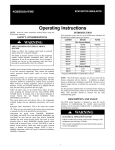
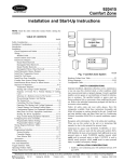
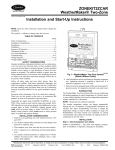
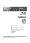
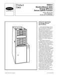
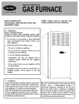
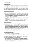
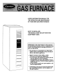
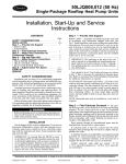
CEPL
WeatherMaker Two-Zone
Installation and Start-Up Instructions
NOTE: Read the entire instruction manual before starting the
installation.
TABLE OF CONTENTS
PAGE
Safety Considerations.....................................................................1
Installation Considerations.............................................................1
Introduction ....................................................................................1
Installation...................................................................................1-4
Sequence Of Operation...............................................................4-6
Troubleshooting .....................................................................6-8
Wiring Diagrams.......................................................................9-16
Care And Maintenance ................................................................16
®
COMFORT ZONING
SYSTEM
SAFETY CONSIDERATIONS
Improper installation, adjustment, alteration, service, maintenance,
or use can cause fire, electrical shock, or other conditions which
may cause personal injury or property damage. Consult a qualified
installer, service agency, or your distributor or branch for information or assistance. The qualified installer or agency must use
factory-authorized kits or accessories when modifying this product. Refer to the individual instructions packaged with the kits or
accessories when installing.
Follow all safety codes and wear safety glasses. Have fire
extinguisher available. Read these instructions thoroughly and
follow all warnings or cautions attached to the unit. Consult local
and state building codes and Sheet Metal and Air Conditioning
National Association (SMACNA) for special installation requirements.
Recognize safety information. This is the safety-alert symbol .
When you see this symbol on the unit or in instructions and
manuals, be alert to the potential for personal injury.
Understand the signal word DANGER, WARNING, or CAUTION. These words are used with the safety-alert symbol. DANGER identifies the most serious hazards which will result in severe
personal injury or death. WARNING signifies hazards that could
result in personal injury or death. CAUTION is used to identify
unsafe practices which would result in minor personal injury or
product and property damage.
INSTALLATION CONSIDERATIONS
1. Install in non-condensing area with ambients between 32°F
and 120°F.
2. Use vibration isolators (flex connectors) on the zone dampers
and ductwork to minimize noise.
3. Place dampers away from areas that may be noise sensitive.
4. TXV is required in air conditioning and heat pump applications.
5. Use separate isolated transformer to supply power to WeatherMaker Two-Zone Center. (40va minimum, class 2, transformer, field supplied)
Y2
Equpiment
Emergency
Y1
Fnc
R
Heat
HP
W1
On
W2 Stat Heat
C
Fnc w/oFan
Off
HP
w/Fan
GY2Y1RW1W2 C
24 VAC Gnd
DX
C1
Op
C
C1
Op
G Y2 Y1
WARNING!
3
There are HOT parts
under this label.
C
REV W1 W2
Duct RC B 0 Y2 Y1 W1 W2 G RH
Sensors
Equipment Term.
A93450
Fig. 1—WeatherMaker Two-Zone System
INTRODUCTION
The WeatherMaker Two-Zone System allows the air conditioning
and heating equipment to control temperatures in 2 distinct spaces
or zones within a building. Each zone has independent temperature
settings controlled by a thermostat.
NOTE: Thermostats are purchased separately.
The comfort temperature settings can change automatically
through the use of schedules if programmable thermostats are
selected. This allows WeatherMaker Two-Zone to change the
temperature settings in zones to reflect occupancy or usage. The
WeatherMaker Two-Zone System uses motorized air volume
control dampers (also called zone dampers) to regulate the flow of
conditioned air into the zones.
INSTALLATION
Step 1—Check Equipment and Jobsite
INSPECT EQUIPMENT — File claim with shipping company,
prior to installation, if shipment is damaged or incomplete.
Step 2—Wiring
To prevent personal injury or possible equipment damage,
disconnect the power supply before routing wire.
All wiring must comply with local, state, and national codes.
Manufacturer reserves the right to discontinue, or change at any time, specifications or designs without notice and without incurring obligations.
Book 1 1 4 4
PC 101
Catalog No. 809-549
Printed in U.S.A.
Form CEPL-1SI
Pg 1
10-93
Replaces: New
Tab 3a 5a 2a 5a
NOTE: Use No. 18 AWG color-coded, insulated (35°C min)
wire. If thermostats are to be located more than 100 ft from the
WeatherMaker Two-Zone Center as measured along the control
voltage wires, use 16 AWG colored-coded wires to avoid excessive voltage drop. All wiring is run back to the WeatherMaker
Two-Zone Center.
ACTUATOR
HOUSING
DAMPER WIRING
TERMINALS
FIELD
INSTALLED
POWER
WIRING
THRU
FIELD
INSTALLED
WIRING
Step 3—Install WeatherMaker Two-Zone
GROMMET
NOTE: WeatherMaker Two-Zone is approved for indoor use
only and should never be installed with any of its components
exposed to the elements. . Do not mount the the WeatherMaker
Two-Zone Center where it will be accessible to children. Do not
locate the center in areas of the home that are noise sensitive since
relays are energized and and de-energized during operation and
may be an annoyance. Install WeatherMaker Two-Zone in an area
with a temperature range between 32°F and 120°F.
OR
CLOSE
OPEN
COMMON
CONDUIT
FACTORY
INSTALLED
WIRING
Fig. 3—Damper 24-vac Connections
Install the WeatherMaker Two-Zone center in a vertical position.
Locate in an area that is easily accessible in case servicing should
be required.
A92474
full-open position, the crank arm connection on the motor’s
threaded shaft will be closest to the motor. In full-closed position,
it will be furthest away from the motor.
If in an emergency it becomes necessary to force a damper open
manually, loosen the setscrews located on the crank and then turn
the damper shaft. To realign, apply 24vac between COM and OP.
Adjust and tighten screws.
To prevent possible damage to the WeatherMaker Two-Zone
Center, do not mount on plenum, ductwork, or flush against
furnace.
Step 4—Install Zone Dampers
To avoid noise and vibration, do not hard mount dampers to any
solid structure such as joists.
IMPORTANT: If conditions exist for possible condensing, the
motor must be positioned for adequate draining. (See Fig. 2.)
NOTE: There is a limit switch at the full-open position and the
full-closed position to stop damper travel.
NOTE: If a multi-damper enabler is used to link dampers
together, then add 5va per damper to the transformer power supply
rating. Reference multi-damper enabler Installation Instructions.
ROUND METAL DUCTWORK
IMPORTANT: If application exists with all metal ductwork
without insulation, flex connectors must be used on each end of the
zone dampers to avoid noise and vibration.
Zone dampers may be installed in any direction.
Position the dampers so that the actuator is visible for inspection
and accessible in the event it would ever need to be replaced. The
black mark on the end of the damper shaft represents the position
of the damper.
DAMPER
1. Crimp end of branch duct.
2. Slip end of flex connector over zone damper and use selftapping sheet metal screw to secure. (See Fig. 4.)
DAMPER
MOTOR
SUPPLY
FLEX
CONNECTOR
ZONE DAMPER
Fig. 4—Round Metal Ductwork
A92477
PA
X
3. Properly seal joint using duct tape, mastic, or other approved
method.
A
IR
4. Insulate damper using 1-1/2-in. to 2-in. insulation. (Check
your local codes.) (See Fig. 5.)
1
/ 2 ″ STEEL STRAP
WIRE POSITION FOR
ADEQUATE DRAINAGE
Fig. 2—Damper Motor Positioning
A93248
NOTE: In some areas where excessive condensing may occur,
carefully insulate over the actuator assembly. Make sure insulation
does not bind crank arm or interfere with operation of actuator.
Before insulating the ductwork, check for proper damper operation. Apply 24vac between COM and OP to open the damper and
COM and CL to close the damper. (See Fig. 3.) The damper will
modulate counter-clockwise to open and clockwise to close. In the
A92475
Fig. 5—Insulated Round Metal Ductwork
2
NOTE: All zone dampers and ductwork must be properly supported according to local codes or SMACNA standards.
FLEXIBLE
DUCT
ZONE
DAMPER
RECTANGULAR METAL DUCTWORK
1. Make connections using S-lock and drives. (See Fig. 6.)
S-LOCK
Fig 8—Round Flexible Ductwork
1/ 2 ″
A92479
STEEL STRAP
SUPPLY
AIR DUCT
DRIVE
ZONE
DAMPER
Fig. 6—Rectangular Metal Ductwork
A92478
A92481
2. Properly seal joint using duct tape, mastic, or other approved
method.
Fig. 9—Insulated Round Flexible Ductwork
3. Insulate damper using 1-1/2-in. to 2-in. insulation. (Check
your local codes.) (See Fig. 7.)
FIBROUS
GLASS
DUCTWORK
FIELD
SUPPLIED
SCREWS
1 1/2 " TO 2"
INSULATION
ZONE
DAMPER
2″ TO 3″
A92480
Fig. 10—Rectangular Fibrous Glass Ductwork
2. Screw field-supplied screws and tabs into zone damper.
3. Properly seal joint using duct tape, mastic, or other approved
method.
4. Insulate damper using 1-1/2-in. to 2-in. insulation. (Check
your local codes.) (See Fig. 11.)
A92483
Fig. 7—Insulated Rectangular Metal Ductwork
NOTE: All zone dampers and ductwork must be properly supported according to local codes or SMACNA standards.
NOTE: There should be a minimum of 4 ft between the zone
damper and the first branch duct if more than 1 branch duct is
downstream of the zone damper.
1 1/ 2 ″ TO 2″
INSULATION
ROUND FLEXIBLE DUCTWORK
1. Slip 1 end of flexible ductwork over 1 end of zone damper.
(See Fig. 8.)
A92482
2. Secure the flexible duct to zone damper using SMACNA or
other approved method.
Fig. 11—Insulated Rectangular Fibrous Glass
Ductwork
3. Properly seal joint using duct tape, mastic, or other approved
method.
Step 5—Install Barometric Bypass Damper
NOTE: The barometric bypass damper is a critical part of the
WeatherMaker Two-Zone System for control of minimum airflow
and noise reduction. It is recommended that the bypass be
installed.
4. Insulate damper using 1-1/2-in. to 2-in. insulation. (Check
your local codes.) (See Fig. 9.)
NOTE: All zone dampers and ductwork must be properly supported according to local codes or SMACNA standards.
The bypass should be installed according to local codes and
SMACNA standards. Be sure the bypass is properly supported.
RECTANGULAR FIBROUS GLASS DUCTWORK
For proper installation, refer to the Installation Instructions packaged with the barometric bypass.
1. Insert 1 end of zone damper into 1 end of fibrous glass
ductwork approximately 2 to 3 in. (See Fig. 10.)
3
This is the basic sequence of operation for the WeatherMaker
Two-Zone System. The actual control of the dampers, HVAC
equipment, and system fan will change with the configuration of
the system. Depending upon the configuration, WeatherMaker
Two-Zone can control heat pumps, furnaces, and dual fuel (this
may require a third party relay interface, depending on equipment
configuration) applications.
Failure to properly install the bypass damper can cause
permanent damage to the HVAC equipment. For single-speed
furnace applications, the bypass air must never exceed 25
percent.
Step 6—Install Duct Temperature Sensor
Step 2—Selection of a System Mode
Locate the duct temperature sensor in the main supply trunk after
the bypass damper and before the first branch. The duct temperature sensor must be radiant shielded to prevent heat from affecting
the correct air temperature.
The first step in any heating or cooling cycle requires WeatherMaker Two-Zone to receive an input from any thermostat located
in a zone. WeatherMaker Two-Zone will then prepare to operate
the heating or cooling equipment as requested by the thermostat.
(See Fig. 12.)
1. Drill a 7/8-in. hole at location in unit where sensor will be
installed.
Step 3—Pre-Positioning Dampers and Starting The System Fan
2. Remove cover and insert sensor probe through 7/8-in. hole.
3. Drill two 1/16-in. holes to accept No. 6 screws through
pre-drilled holes in the duct temperature sensor back plate.
In order to minimize noise and enhance the system operation,
WeatherMaker Two-Zone maintains fully open zone dampers
prior to starting the system fan or the heating/cooling equipment.
The intent is to provide the HVAC equipment with unrestricted
ductwork and to reduce pressure surges. WeatherMaker Two-Zone
also fully opens the dampers whenever a heating or cooling cycle
is completed (this is done after a 90 sec delay). All the zone
dampers will remain fully open until the next heating or cooling
cycle.
4. Use the 2 No. 6 sheet metal screws included with sensor to
mount duct temperature sensor back plate to unit.
5. Insert 2-conductor wiring through 1 of the pre-drilled holes in
side of back plate.
6. Connect sensor to 2-wire conductor using wire nuts provided.
(See Fig. 12 for connection to WeatherMaker Two-Zone
Center.)
The other reason for opening the dampers is to provide unrestricted
ductwork to other equipment which is not directly controlled by
WeatherMaker Two-Zone. One example may be Heating Recovery Ventilator. If WeatherMaker Two-Zone is not actively controlling the HVAC system, then it must not impose any control
influences (such as closed zone dampers) on the system and
prevent proper operation of other devices.
Step 7—Install Dx Coil Sensor
The Dx coil temperature sensor is recommended for use in heat
pump applications and should be installed after the Dx coil and
before the heater elements. It measures the Dx coil temperature
through a temperature sensor, and adds extra protection for
high/low temperature limits. The Dx coil sensor interfaces to the
WeatherMaker Two-Zone Center on terminal marked DX. To
activate the Dx coil temperature sensor, remove factory supplied
resistor from Dx terminal block and replace with sensor leads.
When activated, the Dx sensor has built in non-adjustable heat
LAT setpoints of 105°F and 110°F.
Only the zone 1 thermostat controls continous fan operation. When
the zone 1 thermostat has the fan selector switch in the AUTO
position, the fan will operate only when the heating and cooling
equipment is operating. When the zone 1 thermostat has the fan
selector switch in the ON position, the fan will operate continuously. Zone 2 will not control this.
SEQUENCE OF OPERATION
Step 4— HVAC Equipment Connections
Step 1—Sequence of Events for a Normal Heating or
Cooling Cycle
The WeatherMaker Two-Zone relay outputs are shown in Table 1.
The Y1 and Y2 contacts are used for the compressor contactor
only. WeatherMaker Two-Zone operates the heat pump by energizing the compressor contactor and controlling the reversing
valve through the O relay output. The W1 and W2 contacts are
always used for heat sources. These are heating only units such as
furnaces, strip heaters, etc. The relay outputs for WeatherMaker
Two-Zone are shown in Table 1.
The thermostats will determine if active heating or cooling is
required. If so, the WeatherMaker Two-Zone system will perform
the following:
• Make sure all zone dampers are fully open.
• Energize the HVAC equipment fan.
• Energize the heating or cooling equipment. The equipment may
be a compressor, furnace, strip heater, etc.
• Set the zone damper to the open or closed position based upon the
individual zone demand.
• Energize additional stages of heating or cooling if the thermostat
demand warrants.
• Turn off the heating or cooling equipment when all zones are
satisfied.
• Open all zone dampers when the equipment is turned off (after 90
sec delay).
In automatic changeover, the zoning system works on a first come
first serve basis. If 1 zone is calling for heating and the other for
cooling, the zone which sent its demand to the I/O center first will
operate the equipment in that mode until that zone is satisfied.
Step 5—Duct Temerature Optimizer (LAT−Leaving Air
Temperature)
As the WeatherMaker Two-Zone system operates through a
heating or cooling cycle, the zone demands will change. This
Table 1—Available Heating and Cooling Stages Versus System Type
TYPE OF HVAC
REVERSING VALVE
REVERSING VALVE
COOLING STAGE 1 COOLING STAGE 2
HEAT STAGE 1 HEAT STAGE 2
EQUIPMENT USED
O
O
Single-Stage Heat
Y1
—
Energized
Y1/W1
W2
De-energized
Pump
2-Stage Heat Pump
Y1
Y2
Energized
Y1/W1
W2
De-energized
Cooling Only, any
Y1
Y2
—
W1
W2
—
Heater Type
4
B
G
H
A
J
I
K
D
1
E
C
F
Thermostat
Zone 2
Y2
Y1
R
W1
W2
C
3
2
L
M
CL
Zone
1
OP
Damper
C
N
3
CL
Zone
2
OP
Damper
C
Duct
G
Y1 W1 C DX
Y2 R W2
Thermostat
Zone 1
Rc
B
Sensors
O
Y1 W2 Rh 24v
Y2 W1 G
Equipment
24 VAC
Power
A93524
ZONE 1
I/O CENTER CONNECTIONS
G
Y2 Y1
R
†
G
Y2 Y1
W1 W2
C
†
R
W1 W2
ZONE 2
I/O CENTER CONNECTIONS
Y2 Y1
†
*
C
Y2 Y1
THERMOSTAT/SUBBASE
CONNECTIONS
*
R
W1 W2
C
†
R
W1 W2
*
C
THERMOSTAT/SUBBASE
CONNECTIONS
*
ONLY HOOKUP "C" WHEN SUPPLIED BY THERMOSTAT
† HOOKUP WHEN USING TWO-STAGE THERMOSTATS
WITH TWO-STAGE EQUIPMENT
ONLY HOOKUP "C" WHEN SUPPLIED BY THERMOSTAT
† HOOKUP WHEN USING TWO-STAGE THERMOSTATS
WITH TWO-STAGE EQUIPMENT
A93494
A93495
Fig. 12—WeatherMaker Two-Zone Circuit Board
5
will always have its damper fully open. The other zone in the
system may or may not have an open damper depending upon its
particular needs. If the ductwork is too small (or the air
conditioner/heater is too large), then the zone requiring the
conditioned air may not be able to take enough air to allow your
equipment to operate properly. WeatherMaker Two-Zone will
detect this, and open up the closed damper allowing the equipment
to continue to operate.
changes the actual load that is applied to the HVAC equipment. If
the zone airflows decrease, the cooling equipment will tend to
lower the supply-air temperatures which could tend to exceed the
LAT trip limits. Conversely, the heating equipment will tend to
raise the supply-air temperatures which could exceed high trip
limits. In cooling, when the LAT reaches the non-adjustable low
temperature trip limit (50°F) the LAT algorithm begin operating,
closed dampers are initially opened 3 positions, then 1 position
every 20 sec therafter until full open. WeatherMaker Two-Zone
will not shut down second stage cooling (if used); however, if the
temperature continues to drop to 45°F the zoning system will turn
off both stages of cooling. If the temperature improves the system
will stay in the duct temperature optimizer mode until the LAT
reaches 55°F or higher. At 55°F the LAT algorithm will reset and
return dampers to their original position. In the heating mode,
WeatherMaker Two-Zone will perform the same duct temperature
optimization. The trip limits will be determined by the jumper
setting. (See Fig. 12.) This will continue until the leaving air
temperature (LAT) problem is corrected.
The duct temperature optimizer may be disabled on the
control center. A 10k resistor can be installed in place of the
duct sensor at the terminal block. By disabling the duct
temperature optimizer, the LAT safety algorithm is removed
from the system.
It is highly recommended that you use this control option. The
heating LAT is adjustable for the duct sensor. In this Installation
Instruction, you will find the section showing an adjustment for the
heating LAT. (See Fig. 12.) It is very important that this temperature is properly set. For gas or oil furnaces, the temperature limit
will be in the higher temperature range. For heat pumps the
temperature setting should always be in the lower temperature
range.
This control helps WeatherMaker Two-Zone System cope with
installations where the air conditioning system may suffer from
poor ductwork, improperly sized heating or cooling equipment,
and/or improper settings of the barometric bypass damper. This
control is especially useful in retrofit applications where the size
and routing of the ductwork may not be entirely known or
satisfactory.
If you encounter a situation where 1 zone seems to have poor
ductwork, then the WeatherMaker Two-Zone system is capable of
reverting back to a fully-open, constant-volume system. If this
condition persists, it should always be looked upon as an indication
of a HVAC problem, not a WeatherMaker Two-Zone problem.
The duct temperature optimizer works by controlling how cold or
hot the air inside the supply-air duct gets by monitoring the
temperature of the air inside the supply-air system.
Whenever WeatherMaker Two-Zone is providing heating or cooling, the zone within the home that is asking for the conditioned air
6
Step 1—TROUBLESHOOTING
B
This section contains information to assist you in troubleshooting
problems and errors associated with the WeatherMaker Two-Zone
system.
Step 2—System Diagram, Jumpers, and Switches
NOTE: The duct and Dx onputs must have either a sensor or a
10k resistor connected. 10K ohm resistor in place or with a Dx coil
temperature sensor attached.
1
2
NOTE: Dx coil sensor recommended for heat pump
operation.
NORMAL GAS/
ELECTRICAL
SETTING
NORMAL HEAT
PUMP SETTING
F STAT—Gas/electric thermostat is installed in each zone.
Must be in this position to function properly.
155°F
175°F
HP STAT—Heat pump thermostat is installed in each zone.
This setting not used.
147°F
147°F
164°F
138°F
138°F
153°F
FURNACE—Air conditioning equipment
installed is a cooling only unit.
130°F
130°F
143°F
122°F
122°F
132°F
113°F
113°F
121°F
105°F
105°F
110°F
W/O FAN—When demand for heating exists, fan is controlled by gas/electric furnace.
C
W/FAN—When demand for heating exists,
fan comes on immediately (heat pump
only).
Emergency Heat Switch—This switch should remain
in the OFF position for both furnace and heat pump
operation. It should be switched to the ON position
only upon heat pump compressor failure to provide
emergency heat.
ON
A
EQUIPMENT
SHUTOFF
TEMPERATURE
155°F
HT PUMP—Air conditioning equipment
installed is a heat pump.
3
High
Heating
Temperature
Trip
Limit
Setting—Temperature sensed by duct temperature
sensor. When the duct temperature reaches this
temperature setting, the duct temperature optimizer is
enabled.
If the LAT is exceeded then heating will turn off.
OFF
Damper Fuse—Protects damper from electrical damage (3 Amp).
D
7
Comprotec Override—Momentarily short
pins together for temporary equipment time
delay override. Will change compressor
lockout time form 5 minutes to 30 sec for 1
cycle.
E
J6 jumper−Connects Rc and Rh internally.
F
Emergency heat LED−Will turn on when
emergency Heat is on.
G
Red LED−Used for diagnostic error’s.
Table 2—Troubleshooting
LED CODES
Green flashes 1 time every second and no
other LED’s are flashing.
Green flashes 1 time and Red flashes 1 time
Green flashes 1 time and Red flashes 2 times
Green flashes 1 time and Red flashes 3 times
Green flashes 1 time and Red flashes 4 times
Green flashes 1 time and Red flashes 5 times
Green flashes 2 times and Red flashes 1 time
Grenn flashes 2 times and Red flashes 2 times
Green flashes 2 times and Red flashes 3 times
Green flashes 2 times and Red flashes 4 times
Green flashes 2 times and Red flashes 5 times
Green flashes 3 times and Red flashes 1 time
Green flashes 3 times and Red flashes 2 times
Green flashes 3 times and Red flashes 3 times
Green flashes 3 times and Red flashes 4 times
ERROR DESCRIPTION
ACTION REQUIRED
Normal operation.
None.
Wait until duct temperature cools below exceeded
temperature trip. (Heat leaving air temperature
trip limits set at LAT limits POT on central control
circuit board; range is 110 to 175°F.)
Duct temperature sensor. Second stage heat limit Wait until duct temperature cools below exceeded
exceeded.
temperature trip. Range is 105 to 155°F.
Duct temperature sensor. First stage cool limit
Wait until duct temperature raises above exexceeded; cool will be locked out.
ceeded temperature trip (45°F).
Duct temperature sensor. Second stage cool limit Wait until duct temperature raises above exexceeded.
ceeded temperature trip (50°F).
DX temperature sensor. First stage heat limit ex- Wait until Dx temperature cools below exceeded
ceeded; heat will be locked out.
temperature trip. Fixed at 110°F.
DX temperature sensor error. Second stage heat Wait until Dx temperature cools below exceeded
limit exceeded.
temperature trip. Fixed at 105°F.
DX temperature sensor. First stage cool limit ex- Wait until duct temperature raises above exceeded; cool will be locked out.
ceeded temperature trip (45°F).
DX temperature sensor. Second stage coo limit
Wait until duct temperature raises above exexceeded.
ceeded temperature trip (50°F).
1. Verify that duct temperature sensor or 10K
1. Duct temperature sensor.
ohm resistor is attached to control center at duct
2. Temperature sensor is shorted.
temperature connectors.
2. Replace duct temperature sensor.
1. Verify that duct temperature sensor or 10K
1. Duct temperature sensor.
ohm resistor is attached to control center at duct
2. Temperature sensor is open.
temperature connectors.
2. Replace duct temperature sensor.
1. Verify that Dx temperature sensor or 10K ohm
1. Dx temperature sensor.
resistor is attached to control center at Dx tem2. Temperature sensor is shorted.
perature connectors.
2. Replace Dx temperature sensor.
1. Verify that Dx temperature sensor or 10K ohm
1. Dx temperature sensor.
resistor is attached to control center at Dx tem2. Temperature sensor is open.
perature connectors.
2. Replace Dx temperature sensor.
1. Check for short circuits on damper wire connections at the dampers and control center.
Damper fuse blown.
2. Replace damper fuse.
3. Check damper operation, may need to be replaced.
Fatal control center circuit board failure.
Replace control center.
Duct temperature sensor. First stage heat limit
exceeded; heat will be locked out.
H
Green LED−Flashes once every second for
normal operation, alternates with red led
for diagnostic error’s.
I
Red LED−Displays ON when fan is energized.
J
Red LED−Displays ON when firststage
cooling is energized.
K
Red LED−Displays ON when second stage
cooling is energized.
L
Red LED−Displays ON when reversing
valve is energized.
M
Red LED−Displays ON when first stage of
heat is energized.
N
Red LED−Displays ON when second stage
heat is energized.
O
J2 (Not Shown)−Cut for 50 hz operation.
Located under plastic housing approximately 1-in. above comprotec override.
Step 1—Wiring Diagrams
Table 3—Wiring Diagram Reference
For Fig. 13 and 14
FAN COIL WITH AIR CONDITIONER
Indoor Unit (Fig. 13)
FA4A
FB4A
FK4A
FC4B
OUTDOOR UNIT
Single-Stage
Air Conditioner
Two-Speed
Air Conditioner
(38TD)
FK4B
A
A
B
C*
D
E
Fan Coil With Heat Pump
Indoor Unit (Fig. 14)
OUTDOOR UNIT
Single-Stage
Heat Pump
Two-Speed
Heat Pump
(38YD)
FA4A
FB4A
FC4B
FK4A
FK4B
A
A
B
C*
D
E
* Latent Capacity Control−Required, field supplied. See 2-speed Installation Instructions.
Table 4—Wiring Diagram Reference
For Fig. 15
OUTDOOR UNIT
Single-Speed
Air Conditioner
Two-Speed
Air Conditioner
(38TD)
FURNACE WITH AIR CONDITIONER
Indoor Unit (Fig. 15)
58WAV
58RAP
58PAP
58ZAV
58PAV
58GFA
58VUA
58DFA
58RAV
58VCA
58EFA
58SXC
58SXA
58DXC
58DXA
58EJA
58SXB
A* B
C† D*
E F*
58MXA
58MCA
58MVP
58TUA
58TMA
B
B
B
I
I
G‡
H‡
H‡
J
J
* KGATT0101VSP (Optional) 2-stage relay kit−May help to control over-conditioning.
† KSAIF01012SP B Furnace Interface kit−This is required to allow 2-speed outdoor units to select indooe airflow.
‡ Latent Capacity Control−Required, field supplied. See 2-speed Installation Instructions.
9
STANDARD
SINGLE SPEED
AIR CONDITIONER
ZONE PERFECT SYSTEM
STANDARD
SINGLE SPEED
AIR CONDITIONER
ZONE PERFECT SYSTEM
RH
RH
FAN COIL
FAN COIL
G
G
C
C
W2
W2
W1
R
C
G
Y
W1
R
C
G
Y
Y1
W2
Y1
W2
Y2
W3
Y2
Y/Y2
Y
Y1
O
O
O
B
O
B
L
RC
L
RC
E
W3
E
A
B
A93496
A93497
2-SPEED
AIR CONDITIONER
2-SPEED
AIR CONDITIONER
ZONE PERFECT SYSTEM
RH
ZONE PERFECT SYSTEM
FAN COIL
G
R
R
W2
C
C
W1
G
Y1
W2
FAN COIL
RH
G
R
R
C
C
G
W2
W2
Y
W1
Y
Y2
Y1
Y2
Y1
E
Y2
W3
E
O
W3
B
L
RC
O
L
O
L
B
L
Y1
Y2
RC
D
H
R1
Latent Capacity Control (LCC)
A93498
A93499
R1 = Relay DPST, Pilot Duty,
24-v coil (HN61KK324) or Equivalent.
H = Humidistat, opens on humidity
rise (HL38MG026)
C
Fig. 13−Wiring Diagrams (Fan Coil With Air Conditioner)
10
2-SPEED
AIR CONDITIONER
ZONE PERFECT SYSTEM
FAN COIL
RH
G
R
R
C
C
G
W2
W2
W1
Y1
Y1
Y1
Y/Y2
Y2
Y2
L
L
E
O
W3
B
RC
E
A93500
Fig. 13−Wiring Duagrams (Fan Coil With Air Conditioner) Continued
11
STANDARD
SINGLE SPEED
HEAT PUMP
ZONE PERFECT SYSTEM
STANDARD
SINGLE SPEED
HEAT PUMP
ZONE PERFECT SYSTEM
RH
RH
FAN COIL
FAN COIL
G
G
C
C
W2
C
C
R
R
W2
R
R
W1
W1
G
Y1
W2
Y2
W3
W2
G
Y1
Y1
Y2
W2
W2
Y/Y2
Y
O
O
Y
Y
O
O
O
O
B
B
L
RC
L
RC
E
W3
E
A
B
A93511
A93512
ZONE PERFECT SYSTEM
2-SPEED
HEAT PUMP
2-SPEED
HEAT PUMP
RH
FAN COIL
G
R
R
G
W1
L
L
Y1
W2
W2
R
R
G
C
C
W2
W1
Y1
Y2
E
O
RH
G
W2
Y
FAN COIL
ZONE PERFECT SYSTEM
W3
W3
B
O
O
RC
C
C
W2
W2
Y
Y2
Y1
O
O
Y2
W3
W3
L
L
O
E
B
Y1
RC
Y2
D
H
R1
Latent Capacity Control (LCC)
A93514
R1 = Relay DPST, Pilot Duty,
24-v coil (HN61KK324) or Equivalent.
H = Humidistat, opens on humidity
rise (HL38MG026)
C
A93498
Fig. 14−Wiring Diagrams (Fan Coil With Heat Pump)
12
2-SPEED
HEAT PUMP
FAN COIL
ZONE PERFECT SYSTEM
RH
R
R
G
C
C
G
W2
W2
W2
Y1
Y1
Y1
Y/Y2
Y2
Y2
O
O
L
L
W3
W3
W1
O
B
E
RC
E
A93515
Fig. 14−Wiring Duagrams (Fan Coil With Heat Pump) Continued
13
ZONE PERFECT SYSTEM
STANDARD
SINGLE SPEED
AIR CONDITIONER
ZONE PERFECT SYSTEM
STANDARD
SINGLE SPEED
AIR CONDITIONER
RH
RH
G
VARIABLE SPEED
FURNACE
W2
R
R
W1
FURNACE
G
W2
G
W1
W
Y1
Y
Y
C
C
G
Y1
W
Y2
O
Y
Y
Y2
C
C
O
B
B
(KGATT0101VSP)
RC
RC
RELAY
COIL
1
Black
G
3
re
B
en
A93502
A93511
NOTE: Put set-up Switch
No. 2 at the control
board to the ON
position (up) when using
Two Stage Relay Kit
KGATT0101VSP
Accessory (Optional)
(P5)
CONNECTION AT
CONTROL BOARD
ZONE PERFECT SYSTEM
2-SPEED
AIR CONDITIONER
G
W
W2
R
R
W1
G
G
R
R
G
VARIABLE SPEED
FURNACE
RH
VARIABLE SPEED
FURNACE
RH
A
ZONE PERFECT SYSTEM
2-SPEED
AIR CONDITIONER
Y
Y1
C
C
Y1
W
W2
W1
Y
Y1
C
C
Y2
L
O
Y1
B
Y2
O
Y2
RC
L
B
(KGATT0101VSP)
RC
TO
FURNACE
BLOWER
MOTOR
Y2
RELAY
COIL
1
en
re
(P5)
CONNECTION AT
CONTROL BOARD
ACCESSORY
INTERFACE KIT
C
G
3
ACCESSORY
INTERFACE KIT
TO
FURNACE
BLOWER
MOTOR
KSAIF01012SP
(Required)
Black
A93498
NOTE: Put set-up Switch
No. 2 at the control
board to the ON
position (up) when using
Two Stage Relay Kit
KGATT0101VSP
Accessory (Optional)
D
Fig. 15−Wiring Diagrams (Furnace With Air Conditioner)
14
KSAIF01012SP
(Required)
A93504
2-SPEED
AIR CONDITIONER
ZONE PERFECT SYSTEM
2-SPEED
AIR CONDITIONER
VARIABLE SPEED
FURNACE
RH
R
R
RH
G
G
VARIABLE SPEED
FURNACE
ZONE PERFECT SYSTEM
G
W
R
R
G
C
W
W2
W2
C
C
W1
C
W1
Y2
Y
Y1
L
Y2
Y2
Y
Y1
Y1
Y1
L
Y2
O
O
B
B
RC
RC
E
A93506
(KGATT0101VSP)
A93505
RELAY
COIL
NOTE: Put set-up Switch
No. 2 at the control
board to the ON
position (up) when using
Two Stage Relay Kit
KGATT0101VSP
Accessory (Optional)
1
Black
G
3
re
en
(P5)
CONNECTION AT
CONTROL BOARD
F
2-SPEED
AIR CONDITIONER
ZONE PERFECT SYSTEM
RH
2-SPEED
AIR CONDITIONER
ZONE PERFECT SYSTEM
RH
FURNACE
G
FURNACE
G
R
R
R
R
C
W2
G
W2
G
W1
W
W1
W
Y1
C
C
Y1
C
Y
Y1
Y
Y2
Y2
O
O
B
Y1
B
L
RC
L
RC
Y2
Y2
R1
H
H
A93508
R1
Latent Capacity Control (LCC)
A93507
Latent Capacity Control (LCC)
R1 = Relay DPST, Pilot Duty,
24-v coil (HN61KK324) or Equivalent.
H = Humidistat, opens on humidity
rise (HL38MG026)
R1 = Relay DPST, Pilot Duty,
24-v coil (HN61KK324) or Equivalent.
H = Humidistat, opens on humidity
rise (HL38MG026)
G
H
Fig. 15−Wiring Diagrams (Furnace With Air Conditioner) Continued
15
2-SPEED
AIR CONDITIONER
STANDARD
SINGLE SPEED
AIR CONDITIONER
ZONE PERFECT SYSTEM
ZONE PERFECT SYSTEM
FURNACE
FURNACE
RH
R
RH
R
G
G
G
G
R
W2
W2
W2
W2
W/W1
W/W1
W1
Y1
Y/Y2
Y
C
C
W1
Y/Y2
Y2
C
C
Y1
Y2
Y2
O
O
B
B
RC
RC
Y1
L
I
NOTE: See Furnace Installation Instructions
A93509
(Variable Speed models) – Put set-up Switch No. 2 in the ON position
at the furnace control board
(2-Speed models) – Put set-up Switch No. 2 in the ON position,
Switch No. 1 must be in the OFF position at
the furnace control board
J
A93510
Fig. 15−Wiring Diagrams (Furnace WIth Air Conditioner) Continued
CARE AND MAINTENANCE
For continuing optimum performance and to minimize possible
equipment failure, it is essential that periodic maintenance be
performed on this equipment. Consult your servicing contractor or
User’s Manual for the proper frequency of maintenance. Frequency may vary depending upon geographic areas.
Copyright 1993 CARRIER Corp. • 7310 W. Morris St. • Indianapolis, IN 46231
Step 1—Leave User’s Manual With Homeowner
Explain system operation and maintenance procedures outlined in
User’s Manual.
39003
Manufacturer reserves the right to discontinue, or change at any time, specifications or designs without notice and without incurring obligations.
Book 1 1 4 4
Tab 3a 5a 2a 5a
PC 101
Catalog No. 809-549
Printed in U.S.A.
Form CEPL-1SI
Pg 16
10-93
Replaces: New