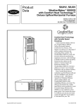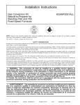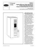
1
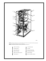
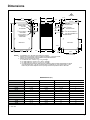
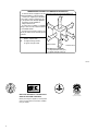
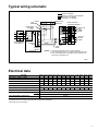
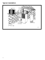
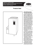
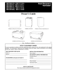
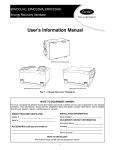
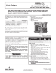
Product
Data
58WAV
WeatherMaker® 8000
Energy-Efficient
Deluxe Upflow Furnace
Series 150 and 160
Input Capacities:
45,000 thru 155,000 Btuh
Advanced Technology
for Energy-Efficient
Gas Furnaces
Carrier leads the industry with its
new WeatherMaker® 8000 InducedDraft Gas Furnace. This furnace is
built with the most advanced
manufacturing equipment, processes,
and technology available in order to
ensure top quality. Packed into the
cabinet are the industry’s foremost
dealer and homeowner features. All
models are GAMA efficiency rating
certified and certified for use in
California Air Quality Management
Districts.
These induced-combustion,
gas-fired furnaces offer not only low
installation costs, but fuel economy as
well — delivering an Annual Fuel
Utilization Efficiency (AFUE) rating
of 80.0 percent. The Carrier
WeatherMaker 8000 utilizes a hot
surface, silicon carbide ignition system
to save energy and increase reliability.
Our design uses the patented
S-shaped 4-pass heat exchanger, a soft
mount inducer assembly, and a slow
opening gas valve to improve sound
level. The Super-S heat exchanger
provides better heat transfer while
enabling us to make a compact furnace.
This provides more room in closet,
utility room, and short basement
installations. The heat exchanger is
constructed of aluminized steel and is
backed by a 20-year Limited Warranty.
The Carrier WeatherMaker 8000
Gas Furnace will meet your home
heating requirements. This furnace
family provides the widest range of
heating capacities available.
The superior attention to cabinet
detail is obvious. The Carrier
WeatherMaker 8000 features 1-piece,
Copyright 2000 Carrier Corporation
Form No. 58WAV-9PD
G
G
R
Y
C
HUM
HUM
24V
HUM COM W
R
G
C
P5
blocked or is not operating properly.
Enhanced indoor air quality in your
home is made easier with our media filter
cabinet—a standard accessory on all deluxe upflow furnaces. When installed as
a part of your system, this cabinet allows
for easy and convenient addition of a
Carrier high-efficiency air filter.
Best of all, the Carrier WeatherMaker 8000 is made to be easily
installed. Many features make this
furnace the easy choice for replacement
or new construction markets. Left and
right connections are provided for gas
and electrical supplies. An easy-toremove bottom, blower speed selector,
cased or uncased cooling coils, lowvoltage humidifier, and electronic air
cleaner terminal connections are among
other features.
2
1
4
5
PL1
6
7
8
F
3 2
1
U S
E
C P L
VOLTAGE S C
O R 2 LINE
NEUTRAL
M 2
E 1
9
3
S
T T
A E
T S
U T
S
LED
E E HEAT COOL
S
A A
E
BLOWER 3
C C SPARE SPARE MOTOR
C
2
1
A 2
2 1
I
N
D
P
L
3
SEE SEPARATE LED STATUS CODE LABEL FOR
INSTRUCTIONS ON CONDUCTING COMPONENT TEST
AND READING STATUS CODES FROM LED.
CAN/CSA - C22.2 NO. 199-M89
ANSI Z21.20 - 1993
INPUT - 24VAC, 465 mA, 60Hz
TEST
WARNING
UNITED TECHNOLOGIES ELECTRONIC CONTROLS
HUNTINGTON, IN 46750
FURNACE CONTROL
1012-940 MODEL HK42FZ011 FOR USE WITH ALL GASES
90 135 180 225
BLOWER-OFF
DELAY
SWITCH SETTING
W
Y
R
SERVICE
SW1
Y
32615
1
BLOWER
OFF DELAY
provides blower delay at start-up and
shutdown, while monitoring furnace
operations and functions. In the
unlikely event of a service call, in less
than a minute, the technician can use the
self-test feature to determine if a major
component has failed. The control
board will check itself, then the inducer,
silicon carbide ignition, low- and highspeed blower, and the humidifier
connections. The control board also
features a 3-amp fuse that protects the
transformer and control board. Another
feature on the control board is an LED
status indicator light to ensure top
furnace performance.
Our induced-combustion furnace has
a patented draft safeguard switch. The
draft safeguard switch will stop furnace
operation if the vent system becomes
W
seamless, wrap-around construction.
There are no spot welds on the exterior
surfaces of the WeatherMaker 8000
Furnace. There is also double protection
for the cabinet. First, a galvanized steel
substrate provides resistance to rusting.
Then the cabinet is constructed of
prepainted steel—the same high-quality
finish found on refrigerators and
dishwashers.
Perhaps the most advanced feature of
the WeatherMaker 8000 is the
microprocessor control board. The
simplified electronics in this control
board provide high reliability while
performing many of the functions of
older, electro-mechanical devices in
other furnaces. Advanced features of
the board show true leadership in
furnace technology. The control board
SEC-1
SEC-2
3
1
S
H
P
L
2
9404
L
1
P
R
1
2
1
LINE
VOLTAGE
120 VAC
COOL SPARE-1
HEAT
P3
SPARE-2
P2
L2
L1
PR1
PR2
COM
A89217
A94151
HEAT EXCHANGER
A92074
CONTROL BOARD
INDUCER BLOWER
Model number nomenclature
58WAV
High-Efficiency
Induced-Combustion
Upflow Furnace
Input Capacity
045 — 44,000 Btuh
070 — 66,000 Btuh
091 — 88,000 Btuh
2
111 — 110,000 Btuh
136 — 132,000 Btuh
155 — 154,000 Btuh
045
150
08
Nominal Cooling Size
(Airflow)
(400 CFM per 12,000 Btuh)
08 — 800 CFM
12 — 1200 CFM
14 — 1400 CFM
16 — 1600 CFM
20 — 2000 CFM
Series Number
9
1
10
2
3
4
5
6
7
8
;;
;;
;;
;;
11
12
A98062
NOTE: The 58WAV Furnaces are for use with natural gas. These furnaces can be field-converted for propane gas
with a factory-authorized and listed accessory conversion kit.
NOTE: Control location and actual control may be different than shown above.
1
Inducer Assembly
7
Air Filter Retainer
2
Pressure Switch
8
Air Filter
3
Gas Control Valve
9
Wrap-Around Casing
4
Burner Assembly
10
Draft Safeguard Switch
5
Blower Door Safety Switch
11
Heat Exchanger
6
Control Board
12
Blower and Blower Motor
3
Carrier accessories*
®
A97432
A97380
MECHANICAL OR
ELECTRONIC AIR
CLEANER
MODEL HUMCCLFP
HUMIDIFIER
Available in programmable and
non-programmable models, Carrier thermostats
maintain a constant comfortable temperature level
in the home.
For the ultimate in home comfort, Carrier’s 2, 4, and
8-zone systems allow temperature control of
individual “zones” of the home. This is
accomplished through a series of electronic
dampers and remote room sensors. The 4-zone
system is shown.
Cleans the air of smoke, dirt, and many pollens
commonly found. Saves decorating and cleaning
expenses by keeping carpets, furniture, and drapes
cleaner.
Electronic air cleaner is shown.
By adding moisture to winter-dry air, a Carrier
humidifier can often improve the comfort and keep
furniture, rugs, and draperies in better condition.
Moisturizing household air also helps to retain
normal body heat and provides comfort at lower
temperatures.
UNIT SIZE
045-08 & 12
070-08 & 12
091-14 & 16
111-12, 16 & 20
ELECTRONIC AIR CLEANER (EAC)
Model AIRA
MECHANICAL AIR CLEANER
Model 31MF
HUMIDIFIER
HEAT RECOVERY VENTILATOR
ENERGY RECOVERY VENTILATOR
THERMOSTAST — NON-PROGRAMMABLE
THERMOSTAT — PROGRAMMABLE
136-16 & 20
155-20
Model HUM
Models HRVCCLHU, HRVCCSVU, or HRVCCLVU
Models ERVCCLHU, ERVCCLVU, or ERVCCSVU
Auto Changeover, °F/°C, 1-Stage Heat/1-Stage Cool — TSTATCCNAC01-B
Auto Changeover, °F/°C, 2-Stage Heat/1-Stage Cool — TSTATCCNHP01-B
Auto Changeover, °F/°C, 2-Stage Heat/2-Stage Cool — TSTATCCN2S01-B
in AC Mode, 3-Stage Heat in AC Mode/2-Stage Cool in HP Mode
Air Conditioner, 1-Stage Heat/1-Stage Cool, Manual Changeover, °F/°C — TSTATCCBAC01
Heat Pump, 2-Stage Heat/1-Stage Cool, Manual Changeover, °F/°C — TSTATCCBHP01**
Auto Changeover, 7-Day Programmable, °F/°C, 1-Stage Heat/1-Stage Cool — TSTATCCPAC01-B
Auto Changeover, 7-Day Programmable, °F/°C, 2-Stage Heat/1-Stage Cool — TSTATCCPHP01-B
Auto Changeover, 7-Day Programmable, °F/°C, 2-Stage Heat/2-Stage Cool — TSTATCCP2S01-B
in AC Mode, 3-Stage Heat/2-Stage Cool in HP Mode
Dual Fuel Thermostat, Includes Outdoor Air Temperature Sensor — TSTATCCPDF01-B**
Thermidistat Control — Non-Programmable/Programmable Thermostat — TSTATCCPRH01-B**
with Humidity Control (For use in Dual Fuel, AC, HP, and 2S applications. Includes Outdoor Air
Temperature Sensor.)
ZONING — 2 ZONE
ZONECC2KIT01, ZONEKIT2ZCAR
ZONING — 4 ZONE
ZONECC4KIT01–B
ZONING — 8 ZONE
ZONECC8KIT01–B
TWINNING KIT†
KGATW0401HSI
GAS CONVERSION KIT* —
NATURAL-TO-PROPANE
KGANP2001ALL
PROPANE-TO-NATURAL
KGAPN1601ALL
* Factory-authorized and field installed. Gas conversion kits are CSA (A.G.A. and C.G.A.) recognized.
† 16 and 20 sizes only.
** Do not use in zoning heat pump applications.
4
A91365
CONTROLS:
THERMOSTATS
AND ZONING
Physical data
045
UNIT SIZE
OUTPUT CAPACITY (BTUH)†
08
Nonweatherized ICS
INPUT BTUH*
070
12
08
091
12
14
111
16
12
16
136
20
16
155
20
20
35,000 35,000 53,000 53,000 71,000 71,000 89,000 89,000 89,000 107,000 107,000 124,000
44,000 44,000 66,000 66,000 88,000 88,000 110,000 110,000 110,000 132,000 132,000 154,000
SHIPPING WEIGHT (Lb)
CERTIFIED TEMP RISE RANGE (°F)
CERTIFIED EXT STATIC PRESSURE
AIRFLOW CFM‡
Heating
122
124
132
134
150
154
160
166
184
179
194
204
25-55
15-45
40-70
30-60
40-70
30-60
55-85
45-75
25-55
50-80
40-70
50-80
0.10
0.10
0.12
0.12
0.15
0.15
0.20
0.20
0.20
0.20
0.20
0.20
Cooling
0.5
0.5
0.5
0.5
0.5
0.5
0.5
0.5
0.5
0.5
0.5
0.5
Heating
855
980
830
1140
1170
1445
1175
1410
1750
1645
1775
1770
Cooling
880
1250
880
1195
1360
1740
1205
1575
2225
1620
2025
2055
5
6
6
7
LIMIT CONTROL
SPST
HEATING BLOWER CONTROL
Solid-State Time Operation
BURNERS (Monoport)
2
2
3
3
4
4
GAS CONNECTION SIZE
5
5
1/2-in. NPT
GAS VALVE (Redundant) Manufacturer
White-Rodgers
Minimum Inlet Pressure (In. wc)
4.5 (Natural Gas)
Maximum Inlet Pressure (In. wc)
13.6 (Natural Gas)
IGNITION DEVICE
Hot Surface
* Gas input ratings are certified for elevations to 2000 ft. For elevations above 2000 ft, reduce ratings 4 percent for each 1000 ft above sea level. Refer to National
Fuel Gas Code Table F4 or furnace Installation Instructions. In Canada, derate the unit 10 percent for elevations 2000 ft to 4500 ft above sea level.
† Capacity in accordance with U.S. Government DOE test procedures.
‡ • Airflow shown is for bottom only return-air supply with factory-supplied 1-in. washable filter(s).
• For air delivery above 1800 CFM, see Air Delivery table for other options.
• An airflow reduction of up to 7% may occur when using the factory specified 4-5/16-inch wide, high efficiency media filter.
• For best furnace efficiency when using the 4-5/16-inch wide media filter, adjust the blower speed tap to near the mid-point of the rise range.
ICS—Isolated Combustion System
Performance data
045
UNIT SIZE
DIRECT-DRIVE MOTOR Hp (PSC)
MOTOR FULL LOAD AMPS
RPM (Nominal) — SPEEDS
070
091
111
136
155
08
12
08
12
14
16
12
16
20
16
20
20
1/5
1/3
1/5
1/3
1/3
1/2
1/3
1/2
3/4
1/2
3/4
3/4
2.9
5.8
2.9
5.8
5.8
7.9
5.8
7.9
11.1
7.9
11.1
11.1
1075-3 1075-4 1075-3 1075-4 1075-4 1075-4 1075-4 1075-4 1075-4 1075-4 1075-4 1075-4
BLOWER WHEEL DIAMETER x WIDTHS (In.)
10 x 6
10 x 6
10 x 6
10 x 6
10 x 7
10 x 8
10 x 7
WASHABLE 16 x 25 x 1-In. FILTER
Qty
1
1
1
1
1
—
1
10 x 8 11 x 10 10 x 8 11 x 10 11 x 10
—
—
—
—
—
WASHABLE 20 x 25 x 1-In. FILTER
Qty
—
—
—
—
—
1
—
1
—
1
—
—
WASHABLE 24 x 25 x 1-In. FILTER
Qty
—
—
—
—
—
—
—
—
1
—
1
1
16
12
20
16
PSC—Permanent Split Capacitor
ENERGY EFFICIENCY
045
UNIT SIZE
08
070
12
08
091
12
14
111
16
136
155
20
20
CAPACITY BTUH*
Nonweatherized ICS 35,000 35,000 53,000 53,000 71,000 71,000 89,000 89,000 89,000 107,000 107,000 124,000
AFUE%*
Nonweatherized ICS
80.0
80.0
80.0
80.0
80.0
80.0
80.0
80.0
80.0
80.0
80.0
80.0
* Capacity and AFUE in accordance with U.S. Government DOE test procedures.
ICS—Isolated Combustion System
5
AIR DELIVERY—CFM (With Filter)*
UNIT SIZE
045-08
RETURN-AIR
SUPPLY
Bottom
or
1 Side
045-12
Bottom
or
1 Side
070-08
Bottom
or
1 Side
070-12
Bottom
or
1 Side
091-14
Bottom
or
1 Side
091-16
Bottom
or
1 Side
111-12
Bottom
or
1 Side
111-16
Bottom
or
1 Side
Bottom
Only
111-20
Both Sides or
1 Side & Bottom
1 Side Only
136-16
Bottom
or 1
Side
Bottom
Only
136-20
Both Sides or
1 Side & Bottom
1 Side Only
Bottom
Only
155-20
Both Sides or
1 Side & Bottom
1 Side Only
EXTERNAL STATIC PRESSURE (In. wc)
SPEED
High
Med-High
Med-Low
High
Med-High
Med-Low
Low
High
Med-High
Med-Low
High
Med-High
Med-Low
Low
High
Med-High
Med-Low
Low
High
Med-High
Med-Low
Low
High
Med-High
Med-Low
Low
High
Med-High
Med-Low
Low
High
Med-High
Med-Low
Low
High
Med-High
High
Med-High
High
Med-High
Med-Low
Low
High
Med-High
Med-Low
Low
High
Med-High
High
Med-High
High
Med-High
Med-Low
Low
High
Med-High
High
Med-High
0.1
1030
855
755
1490
1335
1140
980
1040
855
745
1430
1310
1140
990
1570
1370
1170
1010
2010
1675
1445
1260
1470
1340
1185
1015
1880
1660
1455
1265
—
2125
1745
1545
2475
2100
2415
2080
1900
1695
1460
1275
—
2110
1790
1495
2425
2055
2245
2050
—
—
1790
1520
2405
2090
2325
2085
0.2
1005
830
725
1430
1305
1130
975
1010
830
715
1380
1275
1130
965
1535
1355
1165
1005
1950
1660
1430
1260
1415
1305
1175
1010
1815
1615
1410
1265
2465
2120
1750
1545
2465
2080
2340
2050
1845
1645
1415
1260
2260
2070
1775
1500
2360
2035
2175
1985
2300
2050
1770
1525
2385
2090
2260
2045
0.3
970
800
695
1385
1270
1105
965
975
800
690
1325
1235
1100
960
1480
1330
1150
990
1875
1625
1415
1260
1340
1245
1140
980
1745
1570
1375
1240
2385
2075
1740
1545
2425
2075
2250
2010
1780
1580
1375
1245
2185
2015
1755
1515
2275
1995
2070
1925
2235
2005
1740
1505
2310
2040
2175
1985
0.4
925
765
650
1325
1230
1075
915
935
765
650
1265
1190
1065
935
1415
1290
1115
965
1810
1600
1400
1250
1270
1185
1075
955
1690
1505
1350
1210
2305
2040
1720
1520
2365
2055
2170
1955
1705
1520
1340
1230
2085
1960
1720
1485
2195
1945
1980
1850
2155
1945
1710
1485
2220
1990
2085
1920
0.5
880
720
605
1250
1160
1030
875
880
715
605
1195
1135
1000
905
1360
1240
1085
950
1740
1545
1370
1210
1205
1130
1030
910
1575
1435
1290
1180
2225
1985
1685
1495
2305
2015
2070
1885
1620
1460
1290
1180
2025
1885
1670
1450
2095
1880
1900
1765
2055
1880
1635
1450
2140
1925
2000
1855
0.6
815
670
555
1175
1090
975
840
810
660
550
1125
1065
965
855
1280
1170
1035
905
1660
1490
1325
1180
1115
1045
950
840
1500
1355
1235
1110
2125
1900
1635
1450
2230
1940
2000
1805
1530
1385
1205
1135
1935
1810
1610
1400
2010
1810
1805
1690
1980
1805
1580
1410
2045
1850
1900
1765
0.7
745
595
475
1085
1005
900
785
735
600
475
1045
990
910
800
1185
1080
970
845
1550
1395
1265
1115
985
915
835
725
1400
1260
1145
995
2020
1825
1565
1390
2145
1865
1890
1745
1445
1280
1110
—
1835
1715
1535
1345
1890
1735
1695
1585
1870
1720
1520
1350
1945
1765
1805
1680
0.8
615
485
400
975
915
830
715
640
490
385
945
900
815
710
1070
955
880
745
1455
1295
1170
1030
845
780
705
600
1265
1170
985
855
1910
1715
1500
1330
2015
1765
1780
1645
1320
1155
—
—
1730
1620
1455
1270
1775
1640
1575
1480
1775
1640
1440
1290
1825
1660
1705
1570
* A filter is required for each return-air supply. Airflow shown is with factory supplied 1-in. washable filter(s). An airflow reduction of up to 7% may occur when
using the factory specified 4-5/16-inch wide, high-efficiency media filter. For best furnace efficiency when using the 4-5/16-inch wide media filter, adjust the
blower speed tap to near the mid-point of the rise range.
—Indicates unstable operating conditions.
6
Dimensions
AIRFLOW
28 1⁄2″
2 1⁄16″
VENT CONN
DIA HOLE
POWER ENTRY
7⁄8-IN. DIA
ACCESSORY
7⁄8-IN.
DIA
POWER ENTRY
5 3⁄8″
12 5⁄16″
2 11⁄16″
5 13⁄16″
13⁄16″
1 1⁄2-IN. DIA
R.H. GAS ENTRY
2 3⁄8″
1 3⁄4-IN. DIA HOLE
GAS ENTRY
7⁄8-IN.
DIA HOLE
THERMOSTAT
WIRE ENTRY
DIA ACCESSORY
1⁄2-IN.
DIA THERMOSTAT
WIRE ENTRY
2 3⁄8″
1⁄2-IN.
13⁄16″
OUTLET
1″
5 3⁄8″
5
19″
13⁄16″
1″
7⁄8-IN.
39 7⁄8″
A
D
2 1⁄16″
SIDE INLET
SIDE INLET
141⁄2″
TYP 1″
11⁄4″
24 5⁄16″
AIR INLET
11⁄16″
3″
11⁄16″
E
11⁄16″
1″
231⁄4″
SIDE RETURN
DUCT LOCATION
5⁄8″
TYP
NOTES: 1. Two additional 7⁄8-in. dia holes are located in the top plate.
2. Minimum return-air openings at furnace, based on metal duct. If flex duct is used,
see flex duct manufacturer's recommendations for equivalent diameters.
3. Minimum return-air opening at furnace:
a. For 800 CFM–16-in. round or 141⁄2 x 12-in. rectangle.
b. For 1200 CFM–20-in. round or 141⁄2 x 191⁄2-in. rectangle.
c. For 1600 CFM–22-in. round or 141⁄2 x 231⁄4-in. rectangle.
d. For airflow requirements above 1800 CFM, see Air Delivery table in Product Data literature for specific
use of single side inlets. The use of both side inlets, a combination of 1 side and the bottom, or the
bottom only will ensure adequate return air openings for airflow requirements above 1800 CFM.
A98520
DIMENSIONS (In.)
UNIT SIZE
A
D
E
045-08
14-3/16
12-9/16
11-11/16
VENT CONN* (Dia)
4
045-12
14-3/16
12-9/16
11-11/16
4
070-08
14-3/16
12-9/16
11-11/16
4
070-12
14-3/16
12-9/16
11-11/16
4
091-14
17-1/2
15-7/8
16
4
091-16
21
19-3/8
18-1/2
4
111-12
17-1/2
15-7/8
16
4
111-16
21
19-3/8
18-1/2
4
111-20
24-1/2
22-7/8
22
4
136-16
21
19-3/8
18-1/2
5†
136-20
24-1/2
22-7/8
22
5†
155-20
24-1/2
22-7/8
22
5†
* Refer to the furnace Installation Instructions for proper venting procedures.
† Oval collar
7
MINIMUM INCHES CLEARANCE TO COMBUSTIBLE CONSTRUCTION
TOP / PLENUM
his forced air furnace is equipped for use with This furnace is approved for UPFLOW installations only.
natural gas at altitudes 0 - 10,000 ft (0-3,050m).
n accessory kit, supplied by the manufacturer,
1"
s all be used to convert to propane gas use or
m y be required for some natural gas applications.
his furnace is for indoor installation in
uilding constructed on site.
1"
0"
BA
#
his furnace may be installed on combustible
E
CK
D
SI
E
flooring in alcove or closet at minimum clearance
AC
RN
fr m combustible material.
FU
T
ON
his furnace may be used with a Type B-1 Vent
FR
SE
a nd may be vented in common with other gas-fired
RV
IC
a pliances.
E
E
SI
#
FR
For furnaces wider than 14.25 inches
(362mm) may be 0 inches.
For single wall vent type 6 inches.
For Type B-1 vent type 3 inches.
T
30"
##
0"
Clearance in inches.
ON
MIN
BOTTOM
DESSOUS
#
D
1" #
320325-101 REV. H
Vent Clearance to combustibles:
For Single Wall vents 6 inches (6 po).
For Type B-1 vent type 1 inch (1 po).
A98122E
ama
MEETS DOE RESIDENTIAL CONSERVATION
SERVICES PROGRAM STANDARDS.
Before purchasing this appliance, read important
energy cost and efficiency information available
from your retailer.
8
CERTIFIED
REGISTERED
QUALITY SYSTEM
Typical wiring schematic
FIELD 24-V WIRING
FIELD 115-, 208/230-, 460-V WIRING
FACTORY 24-V WIRING
FACTORY 115-V WIRING
NOTE 2
W
FIVE
WIRE
C
R
G
Y
THERMOSTAT
TERMINALS
FIELD-SUPPLIED
FUSED DISCONNECT
THREE-WIRE
HEATINGONLY
BLK
BLK
W
WHT
WHT
R
GND
GND
AUXILIARY
115-V
FIELD-SUPPLIED J-BOX
CONTROL
DISCONNECT
BOX
208/230- OR
460-V
THREE
PHASE
208/230-V
SINGLE
PHASE
G
C
GND
NOTE 1
CONDENSING
UNIT
Y
TWO
WIRE
24-V
TERMINAL
BLOCK
FURNACE
NOTES: 1. Connect Y-terminal as shown for proper operation.
2. Some thermostats require a "C" terminal connection as shown.
3. If any of the original wire, as supplied, must be replaced, use
same type or equivalent wire.
A98209
Electrical data
UNIT SIZE
045-08 045-12 070-08 070-12 091-14 091-16 111-12 111-16 111-20 136-16 136-20 155-20
115 — 60 — 1
UNIT VOLTS — HERTZ — PHASE
MINIMUM WIRE SIZE
14
14
14
14
14
14
14
14
12
14
12
MAXIMUM WIRE LENGTH (Ft)*
47
34
47
32
31
27
35
28
31
28
33
31
MAXIMUM UNIT AMPS
6.0
8.3
5.9
8.7
9.0
10.4
8.0
10.1
14.4
10.1
13.3
14.0
15
15
15
15
15
15
15
20
15
20
20
OPERATING VOLTAGE RANGE (Min—Max)†
104—127
MAX FUSE OR CKT BKR (Amps)‡
TRANSFORMER (24v)
15
40va
EXTERNAL CONTROL POWER AVAILABLE Heating
Cooling
AIR CONDITIONING BLOWER RELAY
12
12va
35va
Standard
* Length shown is as measured 1 way along wire path between unit and service panel for maximum 2% voltage drop.
† Permissible limits of the voltage range at which the unit will operate satisfactorily.
‡ Time-delay type is recommended.
9
Typical installation
CONDENSING
UNIT
HUMIDIFIER
ELECTRONIC
AIR CLEANER
GAS-FIRED
WATER HEATER
AIRFLOW
A89242
10
11
Carrier Corporation • Indianapolis, IN 46231
10-00
Manufacturer reserves the right to discontinue, or change at any time, specifications or designs without notice and without incurring obligations.
Book
1
Tab
6a 8a
4
Page 12
Catalog No. 525-80004
Printed in U.S.A.
PC 101
Form 58WAV-9PD
Replaces: 58WAV-8PD