1
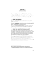
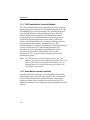
7C03 MMAC SmartSWITCH™
Installation Guide
9031699-01
Notice
NOTICE
Cabletron Systems reserves the right to make changes in
specifications and other information contained in this document
without prior notice. The reader should in all cases consult
Cabletron Systems to determine whether any such changes have
been made.
The hardware, firmware, or software described in this manual is
subject to change without notice.
In no event shall Cabletron Systems be liable for any incidental,
indirect, special, or consequential damages whatsoever (including
but not limited to lost profits) arising out of or related to this
manual or the information contained in it, even if Cabletron
Systems has been advised of, known, or should have known, the
possibility of such damages.
© Copyright February 1996 by:
Cabletron Systems, Inc.
35 Industrial Way
Rochester, NH 03867-0505
All Rights Reserved
Printed in the United States of America
Order Number: 9031699-01
MMAC is a registered trademark of Cabletron Systems, Inc.
MMAC SmartSWITCH, MMAC-M5FNB, and MMAC-M8FNB
are trademarks of Cabletron Systems, Inc.
Ethernet is a trademark of Xerox Corp.
CompuServe is a registered trademark of CompuServe Inc.
i960 microprocessor is a registered trademark of Intel Corp.
i
Notice
FCC NOTICE
This device complies with Part 15 of the FCC rules. Operation is
subject to the following two conditions: (1) this device may not
cause harmful interference, and (2) this device must accept any
interference received, including interference that may cause
undesired operation.
NOTE: This equipment has been tested and found to comply with
the limits for a Class A digital device, pursuant to Part 15 of the
FCC rules. These limits are designed to provide reasonable
protection against harmful interference when the equipment is
operated in a commercial environment. This equipment uses,
generates, and can radiate radio frequency energy and if not
installed in accordance with the operator’s manual, may cause
harmful interference to radio communications. Operation of this
equipment in a residential area is likely to cause interference in
which case the user will be required to correct the interference at
his own expense.
WARNING: Changes or modifications made to this device which
are not expressly approved by the party responsible for
compliance could void the user’s authority to operate the
equipment.
DOC NOTICE
This digital apparatus does not exceed the Class A limits for radio
noise emissions from digital apparatus set out in the Radio
Interference Regulations of the Canadian Department of
Communications.
Le présent appareil numérique n’émet pas de bruits
radioélectriques dépassant les limites applicables aux appareils
numériques de la class A prescrites dans le Règlement sur le
brouillage radioélectrique édicté par le ministère des
Communications du Canada.
ii
Notice
VCCI NOTICE
This equipment is in the 1st Class Category (information
equipment to be used in commercial and/or industrial areas) and
conforms to the standards set by the Voluntary Control Council for
Interference (VCCI) by Information Technology Equipment aimed
at preventing radio interference in commercial and/or industrial
areas.
Consequently, when used in a residential area or in an adjacent
area thereto, radio interference may be caused to radios and TV
receivers, etc.
Read the instructions for correct handling.
iii
Notice
DECLARATION OF CONFORMITY
Application of Council Directive(s):
Manufacturer’s Name:
Manufacturer’s Address:
European Representative Name:
European Representative Address:
89/336/EEC
73/23/EEC
Cabletron Systems, Inc.
35 Industrial Way
PO Box 5005
Rochester, NH 03886-5005
Mr. J. Solari
Cabletron Systems Limited
Nexus House, Newbury Business Park
London Road, Newbury
Berkshire RG13 2PZ, England
Conformance to Directive(s)/Product Standards: EC Directive 89/336/EEC
EC Directive 73/23/EEC
EN55022
EN 50082-1
EN 60950
Equipment Type/Environment:
Networking Equipment, for use in a
Commercial or Light Industrial
Environment.
We the undersigned, hereby declare that the equipment packaged with this notice
conforms to the above directives.
Manufacturer
Legal Representative in Europe
Mr. Richard Michaud
___________________________________
Mr. J. Solari
___________________________________
Full Name
Full Name
Manager of Engineering Services
___________________________________
Title
Managing Director - E.M.E.A.
___________________________________
Title
Rochester, NH, USA
___________________________________
Newbury, Berkshire, England
___________________________________
Location
Location
iv
CONTENTS
CHAPTER 1 INTRODUCTION
1.1 USING THIS MANUAL .........................................................................1-1
1.2 USING THE SMARTSWITCH MANUAL SET ...................................1-1
1.3 7C03 MMAC SMARTSWITCH OVERVIEW .......................................1-2
1.3.1 7X00 SmartSwitch Controller Module ........................................1-4
1.3.2 SmartSwitch interface modules ...................................................1-4
1.3.3 Operations.......................................................................................1-5
1.4 RELATED MANUALS............................................................................1-6
1.5 GETTING HELP.......................................................................................1-6
CHAPTER 2 INSTALLATION
2.1 UNPACKING THE 7C03 MMAC SMARTSWITCH ..........................2-1
2.2 INSTALLING THE 7C03 MMAC SMARTSWITCH...........................2-2
CHAPTER 3 TECHNICAL SPECIFICATIONS
3.1 SERVICE....................................................................................................3-1
3.2 PHYSICAL ................................................................................................3-1
3.2.1 Dimensions .....................................................................................3-1
3.2.2 Weight .............................................................................................3-1
3.3 ENVIRONMENTAL................................................................................3-1
v
CHAPTER 1
INTRODUCTION
Welcome to Cabletron Systems 7C03 MMAC SmartSwitch
Installation Guide. This manual is a simple installation and reference
guide. The 7C03 MMAC SmartSwitch is a unique self-contained
module that can be placed into an MMAC series chassis1.
1.1 USING THIS MANUAL
Chapter 1, Introduction, discusses the features of the 7C03
MMAC SmartSwitch.
Chapter 2, Installation, explains the process of inserting the 7C03
MMAC SmartSwitch in an MMAC chassis.
Chapter 3, Technical Specifications, explains the physical and
operational specifications for the 7C03 MMAC SmartSwitch.
1.2 USING THE SMARTSWITCH MANUAL SET
Each SmartSwitch interface module that can be inserted in the
7C03 MMAC SmartSwitch is shipped with a module user’s guide.
For example, the 7E03-24 Ethernet SmartSwitch Interface Module
User’s Guide explains the physical characteristics, specifications,
and installation procedures of the 7E03-24 Module.
The management module of the 7C03 MMAC SmartSwitch is
described in the 7X00 SmartSwitch Controller Module User’s Guide.
The user’s guide explains the 7X00 Module’s physical
characteristics, installation procedures, and how to locally manage
the SmartSwitch interface modules in the chassis.
1. Refer
to Chapter 2 of this installation guide for information and
considerations regarding the placement of a 7C03 MMAC SmartSwitch in
an MMAC series chassis.
1-1
Introduction
In addition, any local management information that is specific to a
particular SmartSwitch interface module is described in a module
specific local management appendix. For example, the 7E03-24
Ethernet SmartSwitch Interface Module Local Management Appendix
explains information that is specific to local management of the
7E03-24 Module only.
1.3 7C03 MMAC SMARTSWITCH OVERVIEW
The 7C03 MMAC SmartSwitch (Figure 1-1) is a metal enclosure
that can be placed into two module slots of an MMAC chassis. The
7C03 MMAC SmartSwitch attaches to the MMAC chassis’ power
bus, but does not attach to the data channels on the chassis’
backplane. The 7C03 MMAC SmartSwitch can be installed or
removed from the MMAC chassis at any time without affecting the
operation of the rest of the network.
The 7C03 MMAC SmartSwitch has three module slots. The leftmost slot (slot one) is reserved for the 7X00 SmartSwitch Controller
Module, a management module that contains a Smart Switching
engine. The other two slots can support any combination of
Ethernet, Token Ring, FDDI, and ATM SmartSwitch interface
modules.
Spanning the rear wall of the 7C03 MMAC SmartSwitch is the
SmartSwitch Bus. All modules that are inserted into the 7C03
MMAC SmartSwitch connect to the SmartSwitch Bus. All
communication between modules within the 7C03 MMAC
SmartSwitch is achieved via the SmartSwitch Bus.
All data and management information from SmartSwitch interface
modules within the 7C03 MMAC SmartSwitch is relayed along the
SmartSwitch Bus to the 7X00 Module. All switching functions are
performed by the 7X00 Module. Thus, within the confines of the
7C03 MMAC SmartSwitch, data can be freely transmitted
regardless of front panel technology. With no external bridges or
routers, the transfer of data from one point to another within the
7C03 MMAC SmartSwitch is virtually direct.
1-2
Introduction
7X00
7F00
7E03-24
SP
SP
SP
SN
PWR
CPU
24
SN
A
MAC ADR
F
D
D
I
1
10
B
A
S
E
T
SN
P
S
A
B
B
13
P
S
A
B
12
A
F
D
D
I
2
P
S
10
B
A
S
E
T
A
B
B
1
Figure 1-1. 7C03 MMAC SmartSwitch
Because the 7C03 MMAC SmartSwitch does not attach to the data
channels on the backplane of an MMAC chassis, data can not be
transmitted internally from SmartSwitch interface modules to the
other modules in the MMAC chassis. However, data can be
transmitted externally from SmartSwitch interface modules to any
other destination (in the same chassis or elsewhere) via
connections to the front panel of any SmartSwitch interface
module.
1-3
Introduction
1.3.1 7X00 SmartSwitch Controller Module
The 7X00 SmartSwitch Controller Module is the only processing
and management element in the 7C03 MMAC SmartSwitch. The
7X00 Module has no front panel data ports. All data enters and
exits the 7X00 Module via the SmartSwitch Bus on the 7C03
MMAC SmartSwitch’s backplane. The 7X00 Module directs
incoming data to its intended destination by using a group of
Application Specific Integrated Circuits (ASICs) collectively
known as the SmartSwitch Core. All packet switching functions
are performed in the module’s SmartSwitch Core. The
SmartSwitch Core is capable of switching up to 750,000 frames per
second. The firmware on a 7X00 Module determines the
SmartSwitch Core’s operating mode (traditional switch or
SecureFast Packet Switch). The module’s CPU (an i960
microprocessor®) is used to collect management data of the
SmartSwitch system.
Note: The 7X00 Module is not hot-swappable. Because the 7X00
Module is the only processing/management module in the 7C03
MMAC SmartSwitch, removing the 7X00 Module will sever
communications to all SmartSwitch interface modules in the
7C03 MMAC SmartSwitch.
1.3.2 SmartSwitch interface modules
SmartSwitch interface modules in a 7C03 MMAC SmartSwitch
communicate freely with each other via the 7C03’s SmartSwitch
Bus and 7X00 SmartSwitch Controller Module. SmartSwitch
interface modules can be installed or removed from the 7C03
MMAC SmartSwitch at any time without impacting the rest of the
network.
1-4
Introduction
1.3.3 Operations
Data packets entering through the front panel of a SmartSwitch
interface module in the 7C03 MMAC SmartSwitch are converted
by the module’s hardware into frames that have a common
“canonical” format. Canonical frames are forwarded along the
7C03’s SmartSwitch Bus to the 7X00 Module in slot one. The
configuration of the 7X00 Module (either traditional switch or
SecureFast Packet Switch) determines the manner in which
canonical frames are processed.
When operating as a traditional switch (a store-and-forward
switch using the 802.1d Spanning Tree protocol), the 7X00
Module’s SmartSwitch searches for the canonical frame’s
destination address in the module’s connection table. If the
canonical frame’s destination address is found in the connection
table, the frame is forwarded to that specific destination via the
7C03’s SmartSwitch Bus. If the canonical frame’s destination
address is not found in the connection table, the frame is flooded to
all of the SmartSwitch interface modules via the 7C03’s
SmartSwitch Bus.
When operating as a SecureFast Packet Switch, the 7X00 Module’s
SmartSwitch searches for the canonical frame’s destination
address-source address (DA-SA) pair and receive port in the
module’s connection table. If the canonical frame’s entry is found
in the connection table, the frame is forwarded to a specific
destination via the 7C03’s SmartSwitch Bus. If the canonical
frame’s entry is not found in the connection table, a request is sent
to the system’s Virtual Network Services (VNS). The VNS checks
its virtual routing tables and policy sections. If the frame’s
information appears in the VNS’ virtual routing tables and the
VNS’ policy section contains an entry that verifies that the frame’s
source and the frame’s destination are a valid combination, then
the frame is forwarded to its destination via the 7C03’s
SmartSwitch Bus, and a corresponding entry is written to the
receiving module’s connection table. Otherwise, the frame is
dropped.
1-5
Introduction
1.4 RELATED MANUALS
The following manuals supplement the procedures and other
technical data provided in this manual. The procedures will be
referenced where appropriate, but will not be repeated.
Cabletron Systems SmartSwitch Interface Module User’s Guides
(module specific).
Cabletron Systems SmartSwitch Interface Module Local Management
Appendices (module specific).
Cabletron Systems 7X00 SmartSwitch Controller Module User’s Guide
1.5 GETTING HELP
If you need additional support with the 7C03 MMAC
SmartSwitch, or if you have any questions, comments or
suggestions concerning this manual, contact Cabletron Systems
Technical Support:
1-6
By phone:
(603) 332-9400
By fax:
(603) 337-3075
By World Wide Web:
http://www.cabletron.com
By CompuServe®:
GO CTRON from any ! prompt
By Internet mail:
[email protected]
By BBS:
(603) 335-3358
By mail:
Cabletron Systems, Inc.
P.O. Box 5005
Rochester, NH 03886-5005
CHAPTER 2
INSTALLATION
This chapter contains instructions for unpacking and installing the
7C03 MMAC SmartSwitch in an MMAC chassis. The 7C03 MMAC
SmartSwitch can be installed in an MMAC-M5FNB or in an
MMAC-M8FNB chassis.
Note: Because of the modular nature of the power supplies and interface
modules in the MMAC-M5FNB and MMAC-M8FNB chassis,
there is no one standard MMAC configuration that can be used as
a reference. The way you configure your MMAC-M5FNB or
MMAC-M8FNB chassis (number of power supplies, number and
types of interface and management modules) is determined by
your specific needs. Therefore, to insure that the power
requirements of your MMAC will not be exceeded by the addition
of a 7C03 MMAC SmartSwitch, we recommend that you contact
Cabletron Technical Support prior to installing the 7C03 MMAC
SmartSwitch.
2.1 UNPACKING THE 7C03 MMAC SMARTSWITCH
Unpack the 7C03 MMAC SmartSwitch by using the following
steps:
1. Remove the 7C03 MMAC SmartSwitch from the shipping box.
(Save the box and packing materials in the event the 7C03
MMAC SmartSwitch must be reshipped.)
2. Remove the 7C03 MMAC SmartSwitch from the plastic bag.
3. Examine the 7C03 MMAC SmartSwitch and check for damage.
If damage exists, DO NOT install the 7C03 MMAC
SmartSwitch; contact Cabletron Systems Technical Support.
Otherwise, install the 7C03 (see Section 2.2).
2-1
Installation
2.2 INSTALLING THE 7C03 MMAC SMARTSWITCH
Prior to installing the 7C03 MMAC SmartSwitch, please read the
note that appears on page 2-1.
To install the 7C03 MMAC SmartSwitch in an MMAC-M5FNB or
MMAC-M8FNB chassis, use the following steps and refer to
Figure 2-1.
1. Remove the blank panels covering the slots in which the 7C03
MMAC SmartSwitch will be installed. All other unused slots
must remain covered to ensure proper air flow and cooling.
2. Hold the 7C03 MMAC SmartSwitch by the top and bottom
handles and align the plastic rails on the top and bottom of the
7C03 MMAC SmartSwitch with the corresponding card guides
on the MMAC chassis.
3. Slide the 7C03 MMAC SmartSwitch straight into the chassis
until the 7C03 engages the backplane connectors.
4. Tighten the top and bottom thumb screws on the 7C03 MMAC
SmartSwitch.
5. You can now install the 7X00 Module and SmartSwitch
interface modules into the 7C03 MMAC SmartSwitch. Refer to
the applicable module user’s guide for detailed installation
instructions.
2-2
Installation
card
guide
plastic rail
Figure 2-1. Installing the 7C03 MMAC SmartSwitch in an MMAC-M8FNB
2-3
CHAPTER 3
TECHNICAL SPECIFICATIONS
This chapter includes the technical specifications for Cabletron
Systems 7C03 MMAC SmartSwitch. Cabletron Systems reserves
the right to change these specifications at any time without notice.
3.1 SERVICE
MTBF:
>200,000 hours
MTTR:
<0.5 hour
3.2 PHYSICAL
3.2.1 Dimensions
33.1D x 29.2 H x 10 W centimeters
(12.8 D x 9.0 H x 3.9 W inches)
3.2.2 Weight
Unit:
<9.0 kgs. (<20 lbs.)
Shipping:
<9.0 kgs. (<20 lbs.)
3.3 ENVIRONMENTAL
Operating Temperature: +5° to +40° C (+41° to +104° F)
Storage Temperature:
Relative Humidity:
-30° to +80° C (-22° to +160° F)
5 to 95% (non-condensing)
3-1