1
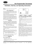
Installation, Start-Up
and Operating Instructions
NON-PROGRAMMABLE THERMOSTATS
Cancels:
New
II TSTAT-0-34
08-04
NOTE: Read the entire instruction manual before starting the
installation.
This symbol → indicates a change since the last issue.
SAFETY CONSIDERATIONS
Read and follow manufacturer instructions carefully. Follow all
local electrical codes during installation. All wiring must conform
to local and national electrical codes. Improper wiring or installation may damage thermostat.
.
Recognize safety information. This is the safety-alert symbol
When you see this symbol on the equipment and in the instruction
manual, be alert to the potential for personal injury.
Understand the signal words DANGER, WARNING, and CAUTION. These words are used with the safety-alert symbol.
DANGER identifies the most serious hazards which will result
in severe personal injury or death. WARNING signifies a hazard
which could result in personal injury or death. CAUTION is used
to identify unsafe practices which would result in minor personal
injury or product and property damage. NOTE is used to highlight
suggestions which may result in enhanced installation, reliability,
or operation.
FAN
TSTATBBNAC01-C
TSTATBBNHP01-C
TSTATBBN2S01-C
A04101
HEIGHT (IN.)
3-1/2
WIDTH (IN.)
5-3/4
DEPTH (IN.)
1-3/8
Fig. 1—Bryant Non-Programmable Thermostat
INTRODUCTION
Bryant thermostats are wall-mounted, low-voltage thermostats
which maintain room temperature by controlling the operation of
a heating and air conditioning system. Separate heating and
cooling setpoints, plus auto changeover provide maximum comfort
and flexibility. Batteries are optional; temperature and mode
settings are preserved with the power off.
•
Close to or in a frequently used room, preferably on an inside
partitioning wall.
•
On a section of wall without pipes or duct work.
Thermostat should NOT be mounted:
INSTALLATION CONSIDERATIONS
POWER
Note that all thermostats are dual powered where batteries can be
installed or in the presence of R and C (24vac) are not required. 2
AA batteries are furnished with the product.
MODELS
There are 3 different models. The 9th and 10th letters of the part
number indicate the model. These 2 letters also appear on the
package and on the circuit board. Be sure to have the proper
thermostat for the intended application. Models are:
AC — 1-stage cool, 1-stage heat for AC systems only.
HP — 1-stage cool, 2-stage heat for either HP, or AC with 2-stage
heat.
2S — 2-stage cool, 2-stage heat for 2-speed AC systems, or
2-stage cool, 3-stage heat for 2-speed HP systems.
•
Close to a window, on an outside wall, or next to a door leading
to the outside.
•
Exposed to direct light and heat from a lamp, sun, fireplace, or
other temperature-radiating object which may cause a false
reading.
•
Close to or in direct airflow from supply registers and return-air
grilles.
•
In areas with poor air circulation, such as behind a door or in
an alcove.
II. SELECT MODEL
AC Model (1-stage cool, 1-stage heat) is to be used for singlestage heating and/or cooling applications only. It CANNOT be
used with optional outdoor temperature sensor. (See Table 1.)
HP Model (1-stage cool, 2-stage heat) can be used with a
single-speed heat pump (HP), or an air conditioner (AC) with a
2-stage furnace or fan coil. Software Option 5 selects HP/AC
operation. This thermostat comes configured from the factory as a
heat pump thermostat. Select AC in software Option 5 for AC
operation. When AC operation is selected, the O/W2 terminal is
converted from a reversing valve output (O) to a second-stage heat
output (W2). This output can be used to control 2-stage furnaces or
2-stage electric heat in fan coils. (See Table 1.)
USE EACH ONLY FOR ITS INTENDED PURPOSE. SEE
TABLE 1.
INSTALLATION
I. THERMOSTAT LOCATION
Thermostat should be mounted:
• Approximately 5 ft. (1.5m) from floor.
2S Model is for 2-speed compressor systems only (HP and AC).
Output Y1 controls compressor low speed and output Y/Y2
controls compressor high speed. (See Table 1.)
—1—
TABLE 1—MODEL SELECTION AND WIRING DIAGRAM CHART
OUTDOOR UNIT
1-Stage
Furnace
2-Stage
Furnace
Typical Fan Coil
Variable-Speed
Fan Coil
(FK4D, FV4, 40FK)
III.
Model AC
See Fig. 3
Model AC
See Fig. 4
AIR CONDITIONER
1 Speed
Model AC
See Fig. 2
Model HP
See Fig. 5
Model HP
See Fig. 6
Model AC
See Fig. 12
Model HP
See Fig. 13
2 Speed
Model 2S
See Fig. 8
Model 2S
See Fig. 9
Model 2S
See Fig. 10
Model 2S
See Fig. 14
INSTALL THERMOSTAT
HEAT PUMP
1 Speed
2 Speed
Requires
Requires
Dual Fuel Thermostat
Dual Fuel Thermostat
Requires
Requires
Dual Fuel Thermostat
Dual Fuel Thermostat
Model HP
Model 2S
See Fig. 7
See Fig. 11
Model HP
See Fig. 15
Model 2S
See Fig. 16
10. Snap case back together.
11. Close thermostat assembly making sure pins on back of
circuit board align with sockets in connector.
12. Turn ON power to unit.
NOTE: If a common wire has not been connected, two AA
batteries must be used to power the thermostat.
On power up, LCD readout will display AC, HP, A2, or H2
depending on the thermostat model status. See "Power On Check"
under "Operational Information" on page 11 for explanation.
IV. SET THERMOSTAT CONFIGURATION
Configuration options are intended to be selected at installation
and are normally not modified by the home owner. These options
are not discussed in the Homeowner’s Guide and therefore must be
made as part of the installation. A special procedure allows entry
into the configuration mode. The thermostat will automatically exit
this mode if no button is pressed for 3 minutes. While in the
configuration mode, up to 14 option choices can be made:
Option 01: Anticipator setting
Option 02: Clean filter setting
Option 03: Fahrenheit or Celsius selection
Option 04: Enable fan (G) on with W/W1 output
Option 05: HP / AC
Option 06: Cooling Lockout (available only if an outdoor air
temperature sensor is present)
Option 07: Enable zoning
Option 08: Auxiliary heat lockout temperature adjustment (available only on heat pump systems and if an outdoor air temperature
sensor is present)
Option 10: O (reversing valve) ON with Heat or Cool (present on
Heat Pump models only)
Option 13: Room temperature offset adjustment
Option 15: Enable AUTO mode
Option 18: Backlight configuration
Option 19: Equipment Present
Option 21: Keypad Lockout
An explanation for each of these and how to enter the configuration mode follows.
TO ENTER THE CONFIGURATION MODE:
To enter Configuration Mode, hold the FAN button down for
approximately 15 seconds. After the 15 second period, Option
″01″ will appear in the display and the SERVICE icon will be
turned on.
NOTE: If the FAN button is pressed again or if no button is
pressed for 3 min, the thermostat will exit the configuration mode
and return to normal operation. To reenter the configuration mode,
the FAN button must be pressed and held for 15 seconds again.
WHILE IN CONFIGURATION MODE:
The display is used to show both the option number and the
selection choice within that option.
A. Option 01—Anticipator Adjustment
This adjustment controls the sensitivity and cycle rate of the
thermostat. Higher numbers decrease the sensitivity and slow the
cycle rate. Lower numbers increase sensitivity and increase cycle
WARNING: ELECTRICAL SHOCK HAZARD
Failure to follow this warning could result in personal
injury or death.
Before installing thermostat, turn off all power to unit.
There may be more than 1 power disconnect.
1. Turn OFF all power to unit.
2. If an existing thermostat is being replaced:
a. Remove existing thermostat from wall.
b. Disconnect wires from existing thermostat, 1 at a time.
Be careful not to allow wires to fall back into the wall.
c. As each wire is disconnected, record wire color and
terminal marking.
d. Discard or recycle old thermostat.
NOTE: Mercury is a hazardous waste and MUST be disposed of
properly.
3. Open thermostat (mounting base) to expose mounting
holes. The base can be removed to simplify mounting. Snap
apart carefully to separate mounting base from remainder of
thermostat.
NOTE: If thermostat will not separate, insert a small screwdriver
into top slots for ease of opening.
4. Route thermostat wires through large hole in mounting
base. Level mounting base against wall (for aesthetic value
only—thermostat need not be leveled for proper operation)
and mark wall through 2 mounting holes.
5. Drill two 3/16-in. mounting holes in wall where marked.
6. Secure mounting base to wall with 2 anchors and screws
provided, (additional anchoring holes available for more
secure mounting if needed) making sure all wires extend
through hole in mounting base.
7. Adjust length and routing of each wire to reach proper
terminal and connector block on mounting base with 1/4 in.
extra wire. Strip only 1/4 in. insulation from each wire to
prevent adjacent wires from shorting together when connected.
8. Match and connect equipment wires to proper terminals of
the connector blocks. (See Table 1.)
CAUTION: ELECTRICAL OPERATION HAZARD
Failure to follow this caution may result in equipment
damage or improper operation.
Improper wiring or installation may damage the thermostat. Check to make sure wiring is correct before proceeding with installation or turning on unit.
9. Push any excess wire into wall and against mounting base.
Seal hole in wall to prevent air leaks. Leaks can affect
operation.
—2—
D. Option 04—G (Fan) On With W/W1 Output
This selection determines whether the G (fan) output is to be ON
or OFF when any W (furnace or strip heat) output is ON. Most
furnaces and fan coils manage their own blowers and do not
require a separate G signal. For these applications, select OFF.
Some auxiliary heaters require a separate G signal to turn on the
blower. In this case, select On. Factory default is OF (off).
TO SELECT:
1. Enter configuration mode (if not already there).
2. Use up and down buttons to display Option 04. The SET
icon should be off.
3. Press MODE button once. The SET icon will come on. The
display now shows Option 04 setting.
4. Use up and down buttons to move between available Option
04 choices of ON or OF. Factory default is OF.
5. Press MODE button again to return to Option 04. The SET
icon will now be off.
6. Use up and down buttons to select another Option, or press
FAN button to exit configuration mode.
E. Option 05 — HP and 2S / AC Configuration
rate. However, a limiting feature will not allow more than 6
equipment cycles per hour, regardless of setting. Values can range
from 1 to 9. Factory default setting is 3. This default selection will
provide optimum performance in nearly all installations. Try it
first. Do not change setting unless there is evidence of need to do
so.
Unlike conventional anticipators, this setting is not to be determined by current draw. There is no need to measure, know, or
compensate for current. There is also no droop with this thermostat, regardless of anticipator setting. This adjustment controls only
sensitivity and cycle rate up to the maximum of 6 cycles per hr.
TO ADJUST:
1. Enter configuration mode (if not already there).
2. Use up and down buttons to display Option 01. The SET
icon should be off.
3. Press MODE button once. The SET icon will come on. The
display now shows Option 01 setting.
4. Use up and down buttons to move between the available
Option 01 values of 1 to 9. Factory default is 3.
5. Press MODE button again to return to Option 01. The SET
icon will now be off.
This configuration is available on HP and 2S models only.
Selecting AC allows the installer to use an HP or 2S thermostat in
an AC application.
TO SELECT:
1. Enter configuration mode (if not already there).
2. Use up and down buttons to display Option 05. The SET
icon should be off.
3. Press MODE button once. The SET icon will come on. The
display now shows Option 05 setting.
4. Use up and down buttons to move between available Option
05 choices of AC or HP. Factory default is HP.
5. Press MODE button again to return to Option 05. The SET
icon will now be off.
6. Use up and down buttons to select another Option, or press
FAN button to exit configuration mode.
F. Option 06—Cooling Lockout
An outdoor air sensor is required for this function. In OF mode,
cooling is available regardless of outdoor temperature. In ON
mode, cooling will not be initiated if the outdoor air temperature is
below 55° F. If the compressor is already operating and the
outdoor air temperature drops below 55° F, the compressor will
continue to operate until the cooling cycle has completed. If the
mode has been set to ON and the outdoor air sensor fails, an E3
error will be displayed.
TO SELECT:
1. Enter configuration mode (if not already there).
2. Use up and down buttons to display Option 06. The SET
icon should be off.
3. Press MODE button once. The SET icon will come on. The
display now shows Option 06 setting.
4. Use up and down buttons to move between available Option
06 choices of OF or ON. Factory default is OF.
5. Press MODE button again to return to Option 06. The SET
icon will now be off.
6. Use up and down buttons to select another Option, or press
FAN button to exit configuration mode.
G. Option 07—Zoning On/Off Configuration
This selection enables or defeats the cycle timer, the staging timer,
and the compressor timeguard. (See "Operational Information" on
page 11 for details.) These timers MUST be enabled (zoning OFF)
for normal operation and disabled (zoning ON) for zoning applications. In zoning applications, the zone control center performs
these timing functions. Factory default is OF.
6. Use up and down buttons to select another Option, or press
FAN button to exit configuration mode.
B.
Option 02—Clean Filter Timer
This option selects the number of hours of blower operation
(heating, cooling, or fan) before SERVICE FILTER icon is
displayed. With OF selected, the icon will never come on,
disabling this feature. Time selection can be from 400 to 3600
hours by selecting numbers 1 through 9. (Time is 400 X number
selected.) Factory default is 2 (800 hours). Recommended selections are: disposable filter 800 hr, media filter 1200 to 1600 hr, or
electronic air cleaner 1600 to 2400 hr of blower operation.
TO ADJUST:
1. Enter configuration mode (if not already there).
2. Use up and down buttons to display Option 02. The SET
icon should be off.
3. Press MODE button once. The SET icon will come on. The
display now shows Option 02 setting.
4. Use up and down buttons to move between the available
Option 02 values of OF and 1 through 9. Factory default is
2.
5. Press MODE button again to return to Option 02. The SET
icon will now be off.
6. Use up and down buttons to select another Option, or press
FAN button to exit configuration mode.
C.
Option 03—Fahrenheit/Celsius Selection
This option selects Fahrenheit or Celsius operation.
TO SELECT:
1. Enter configuration mode (if not already there).
2. Use up and down buttons to display Option 03. The SET
icon should be off.
3. Press MODE button once. The SET icon will come on. The
display now shows Option 03 setting.
4. Use up and down buttons to move between the available
Option 03 choices of F (Fahrenheit) or C (Celsius). Factory
default is F.
5. Press MODE button again to return to Option 03. The SET
icon will now be off.
6. Use up and down buttons to select another Option, or press
FAN button to exit configuration mode.
—3—
TO SELECT:
default is 0. This adjusted value will be used as actual temperature
for both display and control action. For example, if 2 is selected,
72°F actual will read 74°F. If setpoint is 72, the room will control
to an actual value of 70 which will be displayed and acted upon as
if it were 72. The effect is that a positive number selection will
make the room temperature lower and vice versa. This thermostat
is factory calibrated within an accuracy of plus or minus 1°F, so
this adjustment will provide the best accuracy when set to 0.
TO SELECT:
1. Enter configuration mode (if not already there).
2. Use up and down buttons to display Option 07. The SET
icon should be off.
3. Press MODE button once. The SET icon will come on. The
display now shows Option 07 setting.
4. Use up and down buttons to move between available Option
07 choices of ON or OF. Factory default is OF.
1. Enter configuration mode (if not already there).
5. Press MODE button again to return to Option 07. The SET
icon will now be off.
2. Use up and down buttons to display Option 13. The SET
icon should be off.
6. Use up and down buttons to select another Option, or press
FAN button to exit configuration mode.
3. Press MODE button once. The SET icon will come on. The
display now shows Option 13 setting.
H. Option 08—High Ambient Auxiliary Heat Lockout
Present in HP and 2S models only when configured as a heat
pump. Outdoor temperature sensor must be attached. This selection allows lockout of any electric heat (W output) when outdoor
temperature is above a selected temperature. Temperatures of 5° to
55°F (or equivalent values in C) can be selected. Feature can be
disabled by selecting OFF. Emergency heat (EHEAT mode)
always overrides this feature.
4. Use up and down buttons to move between available Option
13 choices of -5 through +5 in 1° steps. Factory default is
0.
5. Press MODE button again to return to Option 13. The SET
icon will now be off.
6. Use up and down buttons to select another Option, or press
FAN button to exit configuration mode.
TO SELECT or ADJUST:
K. Option 15—Auto Mode On/Off Selection
This options allows the installer to enable or disable AUTO mode
(automatic changeover between heat and cool). When disabled,
AUTO icon does not appear when successive presses of MODE
button are used to move between OFF, HEAT, and EHEAT (in
heat pump systems). Factory default is ON (AUTO mode enabled).
TO SELECT:
1. Enter configuration mode (if not already there).
2. Use up and down buttons to display Option 08. The SET
icon should be off.
3. Press MODE button once. The SET icon will come on. The
display now shows Option 08 setting.
4. Use up and down buttons to move between available Option
08 choices of OF, or 5 through 55 in 5° steps. Factory
default is OF.
1. Enter configuration mode (if not already there).
2. Use up and down buttons to display Option 15. The SET
icon should be off.
5. Press MODE button again to return to Option 08. The SET
icon will now be off.
3. Press MODE button once. The SET icon will come on. The
display now shows Option 15 setting.
6. Use up and down buttons to select another Option, or press
FAN button to exit configuration mode.
4. Use up and down buttons to move between available Option
15 choices of ON or OF. Factory default is ON.
I. Option 10 — O (reversing valve) On with Heat or Cool
Selection
5. Press MODE button again to return to Option 15. The SET
icon will now be off.
This selection is only available on HP and 2S model thermostats
when HP is selected via Option 05. This selection determines
whether the reversing valve is energized in the heating or cooling
mode. Factory default is C, energized in cooling. Use up and down
buttons to change between H and C.
TO SELECT:
6. Use up and down buttons to select another Option, or press
FAN button to exit configuration mode.
L. Option 18 — Backlight Configuration
This function is only available when the thermostat is operating
from full power via R and C. It is not available when the
thermostat operates from batteries. In OF (off) mode, this function
is disabled. The thermostat backlight will normally be off. It turns
on with any button press and stays on for 10 seconds in between
button presses. In ON mode, this function is enabled. The
thermostat backlight will normally be on and dim in appearance.
The backlight becomes brighter with any button press and remains
bright for 10 seconds. Factory default is OF.
TO SELECT:
1. Enter configuration mode (if not already there).
2. Use up and down buttons to display Option 10.
3. Press MODE button once. The SET icon will come on. The
display now shows Option 10 setting.
4. Use up and down buttons to move between available Option
10 choices of H (heat) or C (cool). Factory default is C.
5. Press MODE button again to return to Option 10. The SET
icon will now be off.
1. Enter configuration mode (if not already there).
6. Use up and down buttons to select another Option, or press
FAN button to exit configuration mode.
2. Use up and down buttons to display Option 18. The SET
icon should be off.
J. Option 13—Room Temperature Offset
This option allows calibration (or deliberate miscalibration) of
room temperature sensor. There are various reasons why the home
owner may want to have displayed temperature adjusted to a
higher or lower value. The selected number is the number of
degrees, plus or minus, which will be added to the actual
temperature. The number can range between -5 and +5. Factory
3. Press MODE button once. The SET icon will come on. The
display now shows Option 18 setting.
4. Use up and down buttons to move between available Option
18 choices of ON or OF. Factory default is OF.
5. Press MODE button again to return to Option 18. The SET
icon will now be off.
—4—
6. Use up and down buttons to select another Option, or press
FAN button to exit configuration mode.
M. Option 19 — Equipment Present
This selection informs the thermostat of the heat, cool, and fan
capabilities of the installed equipment. Select number 2, 3, or 4.
Default is 4.
For equipment with both heat and cool capability and fan selection,
choose 4.
For equipment with only heat or cool, but with fan selection,
choose 3.
For equipment with only heat or cool and no fan selection, choose
2.
TO SELECT:
1. Enter configuration mode (if not already there).
2. Use up and down buttons to display Option 19. The SET
icon should be off.
3. Press MODE button once. The SET icon will come on. The
display now shows Option 19 setting.
4. Use up and down buttons to move between available Option
19 choices of 2 through 4. Factory default is 4.
5. Press MODE button again to return to Option 19. The SET
icon will now be off.
6. Use up and down buttons to select another Option, or press
FAN button to exit configuration mode.
In installer test mode, pressing the MODE button will change the
system operating mode. Note that AUTO mode is not available in
installer test. Heating and cooling modes must be tested independently.
a. If the mode is set to HEAT, the first stage of heating will
be energized for three minutes (180 seconds), and then
the first and second stages (if a second stage exists) will
turn on for an additional three minutes. Installer test will
always attempt to run a second stage output whether it is
attached or not, providing a minimum of 6 minutes of
first stage operation. At the end of the 6 minute period,
the MODE will return to OFF.
b. Pressing the FAN button while the heating or cooling
equipment is not running will turn on the FAN relay and
display the FAN icon.
c. If the mode is set to COOL, the first stage of cooling
turns on for three minutes, then first and second stages (if
a second stage exists) will turn on for three minutes.
d. If the mode is set to EHEAT, auxiliary heat turns on for
three minutes, then the mode returns to OFF.
Terminating Installer Test
After 15 minutes of inactivity (no button presses by the installer),
thermostat will automatically revert to normal operation. Pressing
RESET FILTER any time during installer test will terminate
installer test and return the thermostat to normal operation.
N. Option 21 — Keypad Lockout
In OF (off) mode, the keypad is not locked out and has full
functionality. In ON mode, the keypad is locked out and the lock
icon on the display is illuminated. To unlock the keypad, the user
must press and hold the up and down buttons simultaneously for
approximately 5 seconds. The lock icon is turned off and the
keypad will remain unlocked as long as the user presses a button
at least every 30 seconds or for the entire duration of the installer
test mode. If keypad remains idle for 30 seconds and the installer
test mode is not in operation, the keypad will return to the locked
state and the lock icon will illuminate on the screen.
TO SELECT:
1. Enter configuration mode (if not already there).
2. Use up and down buttons to display Option 21. The SET
icon should be off.
3. Press MODE button once. The SET icon will come on. The
display now shows Option 21 setting.
4. Use up and down buttons to move between available Option
21 choices of ON or OF. Factory default is OF.
5. Press MODE button again to return to Option 21. The SET
icon will now be off.
6. Use up and down buttons to select another Option, or press
FAN button to exit configuration mode.
O. Installer Test Mode
Installer test will be initiated by pressing the fan button for 20
seconds (15 seconds will enter installer setup. InS will appear on
the screen and the SERVICE icon will be illuminated.
V.
A.
CHECK THERMOSTAT OPERATION
Fan Operation
1. Press FAN button, starting continuous fan operation. FAN
icon turns on.
2. Press FAN button again, stopping fan operation. FAN icon
turns off. (Some fan coils have 90 sec fan off delay, so fan
may not stop immediately.)
B. Outdoor Temperature Sensor
If system is equipped with an outdoor temperature sensor, check its
operation by pressing both, the temperature UP and DOWN
buttons simultaneously. Outdoor temperature will be displayed for
about 5 sec. If ″--″ is displayed, the outdoor temperature sensor is
absent or not properly connected.
C.
Checklist
1. Run equipment through several heating and cooling cycles
to ensure proper operation.
2. If equipment is to be left in operation, set point and
operating mode must be properly selected.
3. Put away tools and instruments, and clean up debris.
4. Review Homeowner’s Guide with owner.
5. Leave literature packet with owner.
—5—
TABLE 2—NON-PROGRAMMABLE -C THERMOSTAT QUICK REFERENCE
TSTAT Model
Outdoor Unit
Option 5
AC01-C
HP01-C
HP01-C
2S01-C
2S01-C
AC
HP
AC
2-Speed AC
2-Speed HP
N/A
OFF
ON
ON
OFF
24v
Hot
R
R
R
R
R
Common
Fan
C
C
C
C
C
G
G
G
G
G
Heat
Stage 1
W/W1
Y/Y2
W/W1
W/W1
Y1
THERMOSTAT OUTPUT
Heat
Heat
Cool
Stage 2 Stage 3 Stage 1
N/A
N/A
Y/Y2
W/W1
N/A
Y/Y2
O/W2/B
N/A
Y/Y2
O/W2/B
N/A
Y1
Y/Y2
W/W1
Y1
Cool
Stage 2
N/A
N/A
N/A
Y/Y2
Y/Y2
Reversing Valve
N/A
O/W2/B
N/A
N/A
O/W2/B
Model Numbers: TSTATBBNAC01-C, TSTATBBNHP01-C, TSTATBBN2S01-C
Note: AC = Air Conditioner, HP = Heat Pump, 2S = 2-Speed, N/A = Not Applicable
MODEL AC 01-C
THERMOSTAT
SINGLE-STAGE
FURNACE
24 VAC HOT
R
R
24 VAC COMM
C
C
HEAT STAGE 1 W/W1
W
COOL STAGE 1 Y/Y2
Y
FAN
G
SINGLE-SPEED
AIR CONDITIONER
MODEL AC 01-C
THERMOSTAT
C
Y
G
TWO-STAGE OR
VARIABLE-SPEED
FURNACE
24 VAC HOT
R
R
24 VAC COMM
C
C
HEAT STAGE 1 W/W1
W/W1
COOL STAGE 1 Y/Y2
Y/Y2
FAN
G
SINGLE-SPEED
AIR CONDITIONER
C
Y
G
HUM
W2
See note 11
Y1
A04006
See note 1 and 11
Fig. 2—Single-Speed Air Conditioner
with Single-Stage Furnace
HUM
A04007
Fig. 3—Single-Speed Air Conditioner
with 2-Stage or Variable-Speed Furnace
MODEL HP 01-C
THERMOSTAT
MODEL AC 01-C
THERMOSTAT
TYPICAL
FAN COIL
24 VAC HOT
R
R
24 VAC COMM
C
C
G
G
24 VAC HOT
R
R
24 VAC COMM
C
C
HEAT STAGE 1 W/W1
W/W1
COOL STAGE 1 Y/Y2
Y/Y2
FAN
SINGLE-SPEED
AIR CONDITIONER
TWO-STAGE OR
VARIABLE-SPEED
FURNACE
G
SINGLE-SPEED
AIR CONDITIONER
C
Y
G
Y1
HUM
FAN
COOL STAGE 1 Y/Y2
HEAT STAGE 1 W/W1
Y
C
HEAT STAGE 2 O/W2/B
*
Y
N/A
Y1
N/A
B
OUTDOOR
S1
W2
W2
W3
E
See notes 2, 3, 4 and 11
SENSOR
CONNECTION
See notes 6, 10 and 11
S2
A98453
A04008
Fig 4—Single-Speed Air Conditioner
with Typical Fan Coil
Fig. 5—Single-Speed Air Conditioner
with 2-Stage or Variable-Speed Furnace
—6—
MODEL HP 01-C
THERMOSTAT
TYPICAL
FAN COIL
24 VAC HOT
R
R
24 VAC COMM
C
C
HEAT STAGE 1 W/W1
W2
COOL STAGE 1 Y/Y2
Y
FAN
G
SINGLE-SPEED
AIR CONDITIONER
*
MODEL HP 01-C
THERMOSTAT
TYPICAL
FAN COIL
SINGLE-SPEED
HEAT PUMP
24 VAC HOT
R
R
R
C
24 VAC COMM
C
C
C
FAN
G
G
Y
COOL/ HEAT
STAGE 1
Y/Y2
Y
G
HEAT STAGE 2 W/W1
*
Y
W2
W2
W3
HEAT STAGE 2 O/W2/B
N/A
Y1
N/A
B
OUTDOOR
S1
E
CONNECTION
N/A
Y1
N/A
B
OUTDOOR
S1
S2
CONNECTION
S2
O
See notes 6, 7, 10 and 11
SENSOR
See notes 2, 4, 6, 10 and 11
SENSOR
E
RVS COOLING O/W2/B
W3
A98456
A98455
Fig. 7—Single-Speed Heat Pump
with Typical Fan Coil
Fig. 6—Single-Speed Air Conditioner
with Typical Fan Coil
MODEL 2S 01-C
THERMOSTAT
SINGLE-STAGE
FURNACE
TWO-SPEED
AIR CONDITIONER
MODEL 2S 01-B
THERMOSTAT
TWO-STAGE OR
VARIABLE-SPEED
FURNACE
TWO-SPEED
AIR CONDITIONER
24 VAC HOT
R
R
R
24 VAC HOT
R
R
R
24 VAC COMM
C
C
C
24 VAC COMM
C
C
C
HEAT STAGE 1 W/W1
W
COOL STAGE 2 Y/Y2
Y
FAN
G
Y2
G
HEAT STAGE 1 W/W1
W/W1
COOL STAGE 2 Y/Y2
Y/Y2
FAN
G
Y2
G
HUM
ACRDJ
N/A
O/W2/B
COOL STAGE 1
Y1
Y1
HEAT STAGE 2 O/W2/B
W2
COOL STAGE 1
Y1
Y1
N/A
B
N/A
B
OUTDOOR
S1
OUTDOOR
S1
SENSOR
Y1
HUM
SENSOR
CONNECTION
S2
See notes 2, 5, 8, and 11
CONNECTION
S2
See notes 2, 3, 4, 8, 9, and 11
A04009
Fig. 8—Two-Speed Air Conditioner
with Single-Stage Furnace
A04010
Fig. 9—Two-Speed Air Conditioner
with 2-Stage or Variable-Speed Furnace
—7—
MODEL 2S 01-c
THERMOSTAT
TYPICAL
FAN COIL
MODEL 2S 01-C
THERMOSTAT
TWO-SPEED
AIR CONDITIONER
TYPICAL
FAN COIL
TWO-SPEED
HEAT PUMP
24 VAC HOT
R
R
R
24 VAC HOT
R
R
R
24 VAC COMM
C
C
C
24 VAC COMM
C
C
C
FAN
G
G
COOL/HEAT
STAGE 2
Y/Y2
Y
HEAT STAGE 1 W/W1
W2
COOL STAGE 2 Y/Y2
Y
FAN
*
Y2
G
G
*
Y2
W2
HEAT STAGE 3 W/W1
W1
W3
HEAT STAGE 2 O/W2/B
COOL STAGE 1
Y1
N/A
B
OUTDOOR
W3
E
RVS COOLING O/B/W2
COOL/HEAT
STAGE 1
Y1
N/A
B
S1
OUTDOOR
S1
S2
CONNECTION
E
Y1
SENSOR
O
Y1
SENSOR
CONNECTION
S2
See notes 5, 6, 7, 8, 10, and 11
See notes 2, 4, 5, 6, 8, 10 and 11
A04011
Fig. 11—Two-Speed Heat Pump
with Typical Fan Coil
A98459
Fig. 10—Two-Speed Air Conditioner
with Typical Fan Coil
MODEL HP 01-C
THERMOSTAT
EASY SELECT
TERMINAL BOARD
SINGLE-SPEED
AIR CONDITIONER
DH
J1 JUMPER
MODEL AC 01-C
THERMOSTAT
EASY SELECT
TERMINAL BOARD
DH
24 VAC HOT
R
HEAT STAGE 1 W/W1
24 VAC HOT
SINGLE-SPEED
AIR CONDITIONER
R
HEAT STAGE 1 W/W1
J1 JUMPER
24 VAC COMM
R
C
COOL STAGE 1 Y/Y2
W1
FAN
J2 JUMPER
G
R
W1
C
C
Y/Y2
Y
G
W2
COOL STAGE 1 Y/Y2
Y/Y2
REMOVE
J2 JUMPER
FOR HEAT
STAGING
Y
HEAT STAGE 2 O/W2/B
FAN
G
G
24 VAC COMM
C
C
N/A
Y1
Y1
N/A
B
O
OUTDOOR
S1
C
See notes 2, 4, 10 and 11
Y1
O
W2
SENSOR
See note 10 and 11
CONNECTION
S2
A98463
A98464
Fig. 12—Single-Speed Air Conditioner
with Variable Speed (FK4D, FV, 40FK) Fan Coil
Fig. 13—Single-Speed Air Conditioner
with Variable-Speed (FK4D, FV, 40FK) Fan Coil
—8—
MODEL 2S
THERMOSTAT
DH
24 VOLT HOT
TWO-SPEED
AIR CONDITIONER
EASY SELECT
TERMINAL BOARD
J1 JUMPER
R
R
24 VOLT COMM
C
C
C
FAN
G
G
COOL STAGE 2 Y/Y2
Y/Y2
HEAT STAGE 1 W/W1
W1
W2
COOL STAGE 1
Y1
Y1
N/A
B
O
OUTDOOR
S1
Y2
24 VAC HOT
R
R
R
24 VAC COMM
C
C
C
FAN
G
G
COOL/HEAT
STAGE 1
Y/Y2
Y/Y2
HEAT STAGE 2 W/W1
Y
W1
REMOVE
J2 JUMPER
FOR HEAT
STAGING
J2 JUMPER
N/A
Y1
Y1
RVS COOLING O/W2
N/A
B
OUTDOOR
S1
W2
W2
O
O
Y1
See notes 7, 8, and 11
SENSOR
S2
See notes 2, 4, 8, 10, and 11
CONNECTION
Fig. 14—Two-Speed Air Conditioner with Variable-Speed
(FK4D, FV4, 40FK) Fan Coil
A04012
MODEL 2S
THERMOSTAT
EASY SELECT
TERMINAL BOARD
TWO-SPEED
HEAT PUMP
DH
J1 JUMPER
24 VAC HOT
R
R
R
24 VAC COMM
C
C
C
FAN
G
G
COOL/HEAT
STAGE 2
Y/Y2
Y/Y2
HEAT STAGE 3 W/W1
Y2
W1
J2 JUMPER
RVS COOLING O/B/W2
COOL/HEAT
STAGE 1
Y1
N/A
B
OUTDOOR
S1
W2
W2
O
O
Y1
Y1
SENSOR
CONNECTION
SINGLE-SPEED
HEAT PUMP
J1 JUMPER
SENSOR
CONNECTION
EASY SELECT
TERMINAL BOARD
DH
R
HEAT STAGE 2 O/B/W2
MODEL HP
THERMOSTAT
S2
See notes 7, 10 and 11
Fig. 16 — Two-Speed Heat Pump with Variable-Speed
(FK4D, FV4) Fan Coil
A04013
—9—
S2
Fig. 15—Single-Speed Heat Pump with Variable-Speed
(FK4D, FV4, 40FK) Fan Coil
A98466
WIRING DIAGRAM NOTES:
1. Furnace must control its own second-stage heat operation via furnace control algorithm. Refer to indoor equipment Installation Instructions
for proper setup.
2. See Option 5 information to convert HP and 2S thermostats to AC thermostat operation.
3. As an option, lock the furnace into low-heat operation and let O/W2/B control high-heat operation. Refer to indoor equipment Installation
Instructions for proper setup.
4. O/W2/B can control second-stage heat. Refer to indoor equipment Installation Instructions for proper setup.
5. Refer to outdoor equipment Installation Instructions for latent kit requirements (if any).
6. Terminals marked with * may not be present on equipment.
7. O/W2/B energizes reversing valve in cooling or heating. See Option 10.
8. Refer to outdoor equipment Installation Instructions for proper setup.
9. If system is wired per diagram, the ACRDJ (jumper) on furnace control board should be removed to allow thermostat to control outdoor
unit staging.
10. Refer to fan coil Installation Instructions for proper wiring.
11. If batteries are installed, C (common wire) is not required between indoor unit and thermostat.
—10—
OPERATIONAL INFORMATION
FIVE-MINUTE COMPRESSOR TIMEGUARD
This timer prevents the compressor from starting unless it has been off for at least 5 minutes. It can be defeated for 1 cycle by simultaneously
pressing the FAN mode button and the INCREASE TEMPERATURE button.
FIFTEEN-MINUTE CYCLE TIMER
This timer prevents the start of a heating or cooling cycle until at least 15 minutes after the last start of the same cycle. Its function is to assure
that equipment is not cycled more than 4 times per hr. This timer is defeated for 1 cycle when the desired temperature is manually changed. It
can also be defeated for 1 cycle by simultaneously pressing the FAN mode button and the INCREASE TEMPERATURE button.
FIFTEEN-MINUTE STAGING TIMER
In multistage heating or cooling, this timer prevents any higher stage from turning on until the preceding stage has been on for 15 minutes. This
timer is defeated if the temperature error is greater than 5°F (usually due to a large change in desired temperature).
THREE-MINUTE MINIMUM ON TIME
In normal operation, when a stage turns on, it will not turn off for a minimum of 3 minutes.
HEAT/COOL SET POINTS (DESIRED TEMPERATURES)
A minimum difference of 2°F is enforced between heating and cooling set points. This is done by allowing one setting to "push" the other, to
maintain this difference.
AUTO CHANGEOVER
When the auto changeover mode is selected, a change from heat to cool (or vice versa) will not occur until an opposite mode demand has existed
for 20 minutes. If the set point is changed, the 20 minute requirement is deleted. Auto mode may be disabled.
EMERGENCY HEAT MODE
When thermostat is configured as a heat pump and emergency heat mode is selected, all Y signals are locked out and W becomes energized upon
a call for heat.
HEAT ON AND COOL ON ICONS
When a heating or cooling demand exists, the HEAT ON or COOL ON icon will either remain on or flash. If flashing, the equipment is temporarily
prevented from turning on by one of the timers (see above). While the icon remains on without flashing, the equipment is on.
POWER ON CHECK
When AC power is first applied, all segments of the display are turned on for a few sec. Following this, the temperature display indicates the
model/configuration via the following 2 digit code:
AC—1-speed air conditioner, HP—1-speed heat pump, A2—2-speed air conditioner, H2—2-speed heat pump.
ERROR CODES
-- — If the thermostat cannot properly read room temperature, the display will indicate -- (2 dashes) and all outputs (except the fan if on) will
turn off. This is to prevent operation of the equipment if the thermostat has failed.
E2 — If the AC line voltage drops below a minimum (brownout) level, all outputs are turned off and the display indicates E2. This condition will
remain for 15 sec after proper line voltage is restored. If the AC line voltage disappears completely, the display will immediately go blank.
E3 — If the thermostat cannot properly read outdoor temperature, and it is needed for proper operation (Heat pump system and Option 8 is not
set to OF), E3 will flash alternately with room temperature.
THERMOSTAT TROUBLESHOOTING
SYMPTOM
Blank LCD
"--" (2 dashes) on temperature display
WHAT TO CHECK
Check for 24vac between R and C at terminal connections or battery.
Temperature sensor reading out of range. Check sensor for damage. If recycling power
does not clear display, thermostat should be replaced.
"E2" on temperature display
Brownout condition or too low of voltage to thermostat. Double check wiring and check for
24vac between R and C. E2 will clear 15 sec after proper voltage is restored.
"E3" on temperature display
The outdoor temperature sensor is open, not connected, or shorted.
"SERVICE FILTER" on temperature display
After the selected number of hour of blower operation "FILTER" will display on LCD. This
is to remind the home owner to "check" the filter. Press RESET FILTER button to clear
display and reset timer to 0.
Cooling will not come on
Select COOL mode. Set desired temperature to 10°F below room temperature. Simultaneously press FAN and INCREASE TEMPERATURE buttons to defeat timers. Check for
COOL ON icon and 24vac at Y (first-stage) terminal. If present, thermostat is OK and
problem is with equipment or wiring. If not present, replace thermostat.
Heating will not come on
Select HEAT mode. Set desired temperature to 10°F above room temperature. Simultaneously press FAN and INCREASE TEMPERATURE buttons to defeat timers. Check for
HEAT ON and 24vac at Y (first-stage) terminal (with heat pump) or W/W1 (with air conditioner) terminal. If present, thermostat is OK and problem is with equipment or wiring. If
not present, replace thermostat.
—11—
N O N - P RO G R A M M A B L E T H E R M O S TAT C O N F I G U R AT I O N R E C O R D
Date
Owner/Operator
Thermostat Model No.
A) Hardware Configuration
Seal hole in wall.
B) Mode Settings
Mode (Off, Heat, Cool, Auto, Eheat)
Heating Set Point Value
Cooling Set Point Value
Fan (Auto or On)
C) Configuration Options
1
Anticipator (1-9: factory default = 3)
2
Clean Filter Timer (Off or 1-9: factory default = 2)
3
Fahrenheit or Celsius (F or C: factory default = F)
4
Fan On with W/W1 output (Off or On: factory default = Off)
5
HP (2-speed) / AC Configuration
6
Cooling Lockout (Off or On: factory default = Off)
7
Zoning Selection (Off or On: factory default = Off)
8
Auxiliary Heat Lockout (Off or 5-55°F: factory default = Off)
9
N/A
10
O(Reversing Valve) ON with Heat or Cool (present on Heat Pump models only.
11-12
N/A
13
Room Temperature Offset (-5 to +5: factory default = 0)
14
N/A
15
Enable Auto Mode (Off or On: factory default = On)
16-17
N/A
18
Backlight Configuration: (On = Continuous; Off = Backlight with Keypress; Default = Off)
19
Equipment Present (2, 3, 4); Default = 4
20
N/A
21
Keypad lockout (Off or On: Default = Off)
© 2004 Bryant Heating & Cooling Systems 7310 W. Morris St. Indianapolis, IN 46231
—12—
Printed in U.S.A.
iitstat-0-34
A04105
Catalog No. 13TS-TA65