1
INSTALLATION AND
OPERATION MANUAL
FCD-E1LC
E1/Fractional E1 Managed Access Unit
Version 1.0
The Access Company
FCD-E1LC
E1/Fractional E1 Managed Access Unit
Version 1.0
Installation and Operation Manual
Notice
This manual contains information that is proprietary to RAD Data Communications Ltd. ("RAD").
No part of this publication may be reproduced in any form whatsoever without prior written
approval by RAD Data Communications.
Right, title and interest, all information, copyrights, patents, know-how, trade secrets and other
intellectual property or other proprietary rights relating to this manual and to the FCD-E1LC and
any software components contained therein are proprietary products of RAD protected under
international copyright law and shall be and remain solely with RAD.
The FCD-E1LC product name is owned by RAD. No right, license, or interest to such trademark is
granted hereunder, and you agree that no such right, license, or interest shall be asserted by
you with respect to such trademark. The RAD name, logo, logotype, and the terms EtherAccess,
TDMoIP and TDMoIP Driven, and the product names Optimux and IPmux, are registered
trademarks of RAD Data Communications Ltd. All other trademarks are the property of their
respective holders.
You shall not copy, reverse compile or reverse assemble all or any portion of the Manual or the
FCD-E1LC. You are prohibited from, and shall not, directly or indirectly, develop, market,
distribute, license, or sell any product that supports substantially similar functionality as the FCDE1LC, based on or derived in any way from the FCD-E1LC. Your undertaking in this paragraph
shall survive the termination of this Agreement.
This Agreement is effective upon your opening of the FCD-E1LC package and shall continue until
terminated. RAD may terminate this Agreement upon the breach by you of any term hereof.
Upon such termination by RAD, you agree to return to RAD the FCD-E1LC and all copies and
portions thereof.
For further information contact RAD at the address below or contact your local distributor.
International Headquarters
RAD Data Communications Ltd.
North America Headquarters
RAD Data Communications Inc.
24 Raoul Wallenberg Street
Tel Aviv 69719, Israel
Tel: 972-3-6458181
Fax: 972-3-6498250, 6474436
E-mail: [email protected]
900 Corporate Drive
Mahwah, NJ 07430, USA
Tel: (201) 5291100, Toll free: 1-800-4447234
Fax: (201) 5295777
E-mail: [email protected]
© 1991–2008 RAD Data Communications Ltd.
Publication No. 289-200-11/08
Limited Warranty
RAD warrants to DISTRIBUTOR that the hardware in the FCD-E1LC to be delivered hereunder shall
be free of defects in material and workmanship under normal use and service for a period of
twelve (12) months following the date of shipment to DISTRIBUTOR.
If, during the warranty period, any component part of the equipment becomes defective by
reason of material or workmanship, and DISTRIBUTOR immediately notifies RAD of such defect,
RAD shall have the option to choose the appropriate corrective action: a) supply a replacement
part, or b) request return of equipment to its plant for repair, or c) perform necessary repair at
the equipment's location. In the event that RAD requests the return of equipment, each party
shall pay one-way shipping costs.
RAD shall be released from all obligations under its warranty in the event that the equipment has
been subjected to misuse, neglect, accident or improper installation, or if repairs or
modifications were made by persons other than RAD's own authorized service personnel, unless
such repairs by others were made with the written consent of RAD.
The above warranty is in lieu of all other warranties, expressed or implied. There are no
warranties which extend beyond the face hereof, including, but not limited to, warranties of
merchantability and fitness for a particular purpose, and in no event shall RAD be liable for
consequential damages.
RAD shall not be liable to any person for any special or indirect damages, including, but not
limited to, lost profits from any cause whatsoever arising from or in any way connected with the
manufacture, sale, handling, repair, maintenance or use of the FCD-E1LC, and in no event shall
RAD's liability exceed the purchase price of the FCD-E1LC.
DISTRIBUTOR shall be responsible to its customers for any and all warranties which it makes
relating to FCD-E1LC and for ensuring that replacements and other adjustments required in
connection with the said warranties are satisfactory.
Software components in the FCD-E1LC are provided "as is" and without warranty of any kind.
RAD disclaims all warranties including the implied warranties of merchantability and fitness for a
particular purpose. RAD shall not be liable for any loss of use, interruption of business or
indirect, special, incidental or consequential damages of any kind. In spite of the above RAD
shall do its best to provide error-free software products and shall offer free Software updates
during the warranty period under this Agreement.
RAD's cumulative liability to you or any other party for any loss or damages resulting from any
claims, demands, or actions arising out of or relating to this Agreement and the FCD-E1LC shall
not exceed the sum paid to RAD for the purchase of the FCD-E1LC. In no event shall RAD be
liable for any indirect, incidental, consequential, special, or exemplary damages or lost profits,
even if RAD has been advised of the possibility of such damages.
This Agreement shall be construed and governed in accordance with the laws of the State of
Israel.
Product Disposal
To facilitate the reuse, recycling and other forms of recovery of waste
equipment in protecting the environment, the owner of this RAD product is
required to refrain from disposing of this product as unsorted municipal
waste at the end of its life cycle. Upon termination of the unit’s use,
customers should provide for its collection for reuse, recycling or other form
of environmentally conscientious disposal.
General Safety Instructions
The following instructions serve as a general guide for the safe installation and operation of
telecommunications products. Additional instructions, if applicable, are included inside the
manual.
Safety Symbols
This symbol may appear on the equipment or in the text. It indicates potential
safety hazards regarding product operation or maintenance to operator or service
personnel.
Warning
Danger of electric shock! Avoid any contact with the marked surface while the
product is energized or connected to outdoor telecommunication lines.
Protective ground: the marked lug or terminal should be connected to the building
protective ground bus.
Warning
Some products may be equipped with a laser diode. In such cases, a label with the
laser class and other warnings as applicable will be attached near the optical
transmitter. The laser warning symbol may be also attached.
Please observe the following precautions:
•
Before turning on the equipment, make sure that the fiber optic cable is intact
and is connected to the transmitter.
•
Do not attempt to adjust the laser drive current.
•
Do not use broken or unterminated fiber-optic cables/connectors or look
straight at the laser beam.
•
The use of optical devices with the equipment will increase eye hazard.
•
Use of controls, adjustments or performing procedures other than those
specified herein, may result in hazardous radiation exposure.
ATTENTION: The laser beam may be invisible!
In some cases, the users may insert their own SFP laser transceivers into the product. Users are
alerted that RAD cannot be held responsible for any damage that may result if non-compliant
transceivers are used. In particular, users are warned to use only agency approved products that
comply with the local laser safety regulations for Class 1 laser products.
Always observe standard safety precautions during installation, operation and maintenance of
this product. Only qualified and authorized service personnel should carry out adjustment,
maintenance or repairs to this product. No installation, adjustment, maintenance or repairs
should be performed by either the operator or the user.
Handling Energized Products
General Safety Practices
Do not touch or tamper with the power supply when the power cord is connected. Line voltages
may be present inside certain products even when the power switch (if installed) is in the OFF
position or a fuse is blown. For DC-powered products, although the voltages levels are usually
not hazardous, energy hazards may still exist.
Before working on equipment connected to power lines or telecommunication lines, remove
jewelry or any other metallic object that may come into contact with energized parts.
Unless otherwise specified, all products are intended to be grounded during normal use.
Grounding is provided by connecting the mains plug to a wall socket with a protective ground
terminal. If a ground lug is provided on the product, it should be connected to the protective
ground at all times, by a wire with a diameter of 18 AWG or wider. Rack-mounted equipment
should be mounted only in grounded racks and cabinets.
Always make the ground connection first and disconnect it last. Do not connect
telecommunication cables to ungrounded equipment. Make sure that all other cables are
disconnected before disconnecting the ground.
Some products may have panels secured by thumbscrews with a slotted head. These panels may
cover hazardous circuits or parts, such as power supplies. These thumbscrews should therefore
always be tightened securely with a screwdriver after both initial installation and subsequent
access to the panels.
Connecting AC Mains
Make sure that the electrical installation complies with local codes.
Always connect the AC plug to a wall socket with a protective ground.
The maximum permissible current capability of the branch distribution circuit that supplies power
to the product is 16A. The circuit breaker in the building installation should have high breaking
capacity and must operate at short-circuit current exceeding 35A.
Always connect the power cord first to the equipment and then to the wall socket. If a power
switch is provided in the equipment, set it to the OFF position. If the power cord cannot be
readily disconnected in case of emergency, make sure that a readily accessible circuit breaker or
emergency switch is installed in the building installation.
In cases when the power distribution system is IT type, the switch must disconnect both poles
simultaneously.
Connecting DC Power
Unless otherwise specified in the manual, the DC input to the equipment is floating in reference
to the ground. Any single pole can be externally grounded.
Due to the high current capability of DC power systems, care should be taken when connecting
the DC supply to avoid short-circuits and fire hazards.
DC units should be installed in a restricted access area, i.e. an area where access is authorized
only to qualified service and maintenance personnel.
Make sure that the DC power supply is electrically isolated from any AC source and that the
installation complies with the local codes.
The maximum permissible current capability of the branch distribution circuit that supplies power
to the product is 16A. The circuit breaker in the building installation should have high breaking
capacity and must operate at short-circuit current exceeding 35A.
Before connecting the DC supply wires, ensure that power is removed from the DC circuit. Locate
the circuit breaker of the panel board that services the equipment and switch it to the OFF
position. When connecting the DC supply wires, first connect the ground wire to the
corresponding terminal, then the positive pole and last the negative pole. Switch the circuit
breaker back to the ON position.
A readily accessible disconnect device that is suitably rated and approved should be incorporated
in the building installation.
If the DC power supply is floating, the switch must disconnect both poles simultaneously.
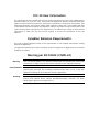
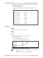
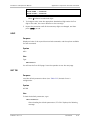
Connecting Data and Telecommunications Cables
Data and telecommunication interfaces are classified according to their safety status.
The following table lists the status of several standard interfaces. If the status of a given port
differs from the standard one, a notice will be given in the manual.
Ports
Safety Status
V.11, V.28, V.35, V.36, RS-530, X.21,
10 BaseT, 100 BaseT, Unbalanced E1,
E2, E3, STM, DS-2, DS-3, S-Interface
ISDN, Analog voice E&M
SELV
xDSL (without feeding voltage),
Balanced E1, T1, Sub E1/T1
TNV-1 Telecommunication Network Voltage-1:
FXS (Foreign Exchange Subscriber)
TNV-2 Telecommunication Network Voltage-2:
Ports whose normal operating voltage exceeds the
limits of SELV (usually up to 120 VDC or telephone
ringing voltages), on which overvoltages from
telecommunication networks are not possible. These
ports are not permitted to be directly connected to
external telephone and data lines.
FXO (Foreign Exchange Office), xDSL
(with feeding voltage), U-Interface
ISDN
TNV-3 Telecommunication Network Voltage-3:
Ports whose normal operating voltage exceeds the
limits of SELV (usually up to 120 VDC or telephone
ringing voltages), on which overvoltages from
telecommunication networks are possible.
Safety Extra Low Voltage:
Ports which do not present a safety hazard. Usually
up to 30 VAC or 60 VDC.
Ports whose normal operating voltage is within the
limits of SELV, on which overvoltages from
telecommunications networks are possible.
Always connect a given port to a port of the same safety status. If in doubt, seek the assistance
of a qualified safety engineer.
Always make sure that the equipment is grounded before connecting telecommunication cables.
Do not disconnect the ground connection before disconnecting all telecommunications cables.
Some SELV and non-SELV circuits use the same connectors. Use caution when connecting cables.
Extra caution should be exercised during thunderstorms.
When using shielded or coaxial cables, verify that there is a good ground connection at both
ends. The grounding and bonding of the ground connections should comply with the local codes.
The telecommunication wiring in the building may be damaged or present a fire hazard in case of
contact between exposed external wires and the AC power lines. In order to reduce the risk,
there are restrictions on the diameter of wires in the telecom cables, between the equipment
and the mating connectors.
Caution
To reduce the risk of fire, use only No. 26 AWG or larger telecommunication line
cords.
Attention
Pour réduire les risques s’incendie, utiliser seulement des conducteurs de
télécommunications 26 AWG ou de section supérieure.
Some ports are suitable for connection to intra-building or non-exposed wiring or cabling only. In
such cases, a notice will be given in the installation instructions.
Do not attempt to tamper with any carrier-provided equipment or connection hardware.
Electromagnetic Compatibility (EMC)
The equipment is designed and approved to comply with the electromagnetic regulations of
major regulatory bodies. The following instructions may enhance the performance of the
equipment and will provide better protection against excessive emission and better immunity
against disturbances.
A good ground connection is essential. When installing the equipment in a rack, make sure to
remove all traces of paint from the mounting points. Use suitable lock-washers and torque. If an
external grounding lug is provided, connect it to the ground bus using braided wire as short as
possible.
The equipment is designed to comply with EMC requirements when connecting it with unshielded
twisted pair (UTP) cables. However, the use of shielded wires is always recommended, especially
for high-rate data. In some cases, when unshielded wires are used, ferrite cores should be
installed on certain cables. In such cases, special instructions are provided in the manual.
Disconnect all wires which are not in permanent use, such as cables used for one-time
configuration.
The compliance of the equipment with the regulations for conducted emission on the data lines
is dependent on the cable quality. The emission is tested for UTP with 80 dB longitudinal
conversion loss (LCL).
Unless otherwise specified or described in the manual, TNV-1 and TNV-3 ports provide secondary
protection against surges on the data lines. Primary protectors should be provided in the building
installation.
The equipment is designed to provide adequate protection against electro-static discharge (ESD).
However, it is good working practice to use caution when connecting cables terminated with
plastic connectors (without a grounded metal hood, such as flat cables) to sensitive data lines.
Before connecting such cables, discharge yourself by touching ground or wear an ESD preventive
wrist strap.
FCC-15 User Information
This equipment has been tested and found to comply with the limits of the Class A digital device,
pursuant to Part 15 of the FCC rules. These limits are designed to provide reasonable protection
against harmful interference when the equipment is operated in a commercial environment. This
equipment generates, uses and can radiate radio frequency energy and, if not installed and used
in accordance with the Installation and Operation manual, may cause harmful interference to the
radio communications. Operation of this equipment in a residential area is likely to cause harmful
interference in which case the user will be required to correct the interference at his own
expense.
Canadian Emission Requirements
This Class A digital apparatus meets all the requirements of the Canadian Interference-Causing
Equipment Regulation.
Cet appareil numérique de la classe A respecte toutes les exigences du Règlement sur le matériel
brouilleur du Canada.
Warning per EN 55022 (CISPR-22)
Warning
Avertissement
Achtung
This is a class A product. In a domestic environment, this product may cause radio
interference, in which case the user will be required to take adequate measures.
Cet appareil est un appareil de Classe A. Dans un environnement résidentiel, cet
appareil peut provoquer des brouillages radioélectriques. Dans ces cas, il peut être
demandé à l’utilisateur de prendre les mesures appropriées.
Das vorliegende Gerät fällt unter die Funkstörgrenzwertklasse A. In Wohngebieten
können beim Betrieb dieses Gerätes Rundfunkströrungen auftreten, für deren
Behebung der Benutzer verantwortlich ist.
Français
Mise au rebut du produit
Afin de faciliter la réutilisation, le recyclage ainsi que d'autres formes de
récupération d'équipement mis au rebut dans le cadre de la protection de
l'environnement, il est demandé au propriétaire de ce produit RAD de ne pas
mettre ce dernier au rebut en tant que déchet municipal non trié, une fois
que le produit est arrivé en fin de cycle de vie. Le client devrait proposer des
solutions de réutilisation, de recyclage ou toute autre forme de mise au rebut
de cette unité dans un esprit de protection de l'environnement, lorsqu'il aura
fini de l'utiliser.
Instructions générales de sécurité
Les instructions suivantes servent de guide général d'installation et d'opération sécurisées des
produits de télécommunications. Des instructions supplémentaires sont éventuellement
indiquées dans le manuel.
Symboles de sécurité
Ce symbole peut apparaitre sur l'équipement ou dans le texte. Il indique des risques
potentiels de sécurité pour l'opérateur ou le personnel de service, quant à
l'opération du produit ou à sa maintenance.
Avertissement
Danger de choc électrique ! Evitez tout contact avec la surface marquée tant que le
produit est sous tension ou connecté à des lignes externes de télécommunications.
Mise à la terre de protection : la cosse ou la borne marquée devrait être connectée
à la prise de terre de protection du bâtiment.
•
Avant la mise en marche de l'équipement, assurez-vous que le câble de fibre
optique est intact et qu'il est connecté au transmetteur.
•
Ne tentez pas d'ajuster le courant de la commande laser.
•
N'utilisez pas des câbles ou connecteurs de fibre optique cassés ou sans
terminaison et n'observez pas directement un rayon laser.
•
L'usage de périphériques optiques avec l'équipement augmentera le risque pour
les yeux.
•
L'usage de contrôles, ajustages ou procédures autres que celles spécifiées ici
pourrait résulter en une dangereuse exposition aux radiations.
ATTENTION : Le rayon laser peut être invisible !
Les utilisateurs pourront, dans certains cas, insérer leurs propres émetteurs-récepteurs Laser SFP
dans le produit. Les utilisateurs sont avertis que RAD ne pourra pas être tenue responsable de
tout dommage pouvant résulter de l'utilisation d'émetteurs-récepteurs non conformes. Plus
particulièrement, les utilisateurs sont avertis de n'utiliser que des produits approuvés par
l'agence et conformes à la réglementation locale de sécurité laser pour les produits laser de
classe 1.
Respectez toujours les précautions standards de sécurité durant l'installation, l'opération et la
maintenance de ce produit. Seul le personnel de service qualifié et autorisé devrait effectuer
l'ajustage, la maintenance ou les réparations de ce produit. Aucune opération d'installation,
d'ajustage, de maintenance ou de réparation ne devrait être effectuée par l'opérateur ou
l'utilisateur.
Manipuler des produits sous tension
Règles générales de sécurité
Ne pas toucher ou altérer l'alimentation en courant lorsque le câble d'alimentation est branché.
Des tensions de lignes peuvent être présentes dans certains produits, même lorsque le
commutateur (s'il est installé) est en position OFF ou si le fusible est rompu. Pour les produits
alimentés par CC, les niveaux de tension ne sont généralement pas dangereux mais des risques
de courant peuvent toujours exister.
Avant de travailler sur un équipement connecté aux lignes de tension ou de télécommunications,
retirez vos bijoux ou tout autre objet métallique pouvant venir en contact avec les pièces sous
tension.
Sauf s'il en est autrement indiqué, tous les produits sont destinés à être mis à la terre durant
l'usage normal. La mise à la terre est fournie par la connexion de la fiche principale à une prise
murale équipée d'une borne protectrice de mise à la terre. Si une cosse de mise à la terre est
fournie avec le produit, elle devrait être connectée à tout moment à une mise à la terre de
protection par un conducteur de diamètre 18 AWG ou plus. L'équipement monté en châssis ne
devrait être monté que sur des châssis et dans des armoires mises à la terre.
Branchez toujours la mise à la terre en premier et débranchez-la en dernier. Ne branchez pas des
câbles de télécommunications à un équipement qui n'est pas mis à la terre. Assurez-vous que
tous les autres câbles sont débranchés avant de déconnecter la mise à la terre.
Français
Certains produits peuvent être équipés d'une diode laser. Dans de tels cas, une
étiquette indiquant la classe laser ainsi que d'autres avertissements, le cas échéant,
sera jointe près du transmetteur optique. Le symbole d'avertissement laser peut
aussi être joint.
Avertissement
Veuillez observer les précautions suivantes :
Français
Connexion au courant du secteur
Assurez-vous que l'installation électrique est conforme à la réglementation locale.
Branchez toujours la fiche de secteur à une prise murale équipée d'une borne protectrice de mise
à la terre.
La capacité maximale permissible en courant du circuit de distribution de la connexion alimentant
le produit est de 16A. Le coupe-circuit dans l'installation du bâtiment devrait avoir une capacité
élevée de rupture et devrait fonctionner sur courant de court-circuit dépassant 35A.
Branchez toujours le câble d'alimentation en premier à l'équipement puis à la prise murale. Si un
commutateur est fourni avec l'équipement, fixez-le en position OFF. Si le câble d'alimentation ne
peut pas être facilement débranché en cas d'urgence, assurez-vous qu'un coupe-circuit ou un
disjoncteur d'urgence facilement accessible est installé dans l'installation du bâtiment.
Le disjoncteur devrait déconnecter simultanément les deux pôles si le système de distribution de
courant est de type IT.
Connexion d'alimentation CC
Sauf s'il en est autrement spécifié dans le manuel, l'entrée CC de l'équipement est flottante par
rapport à la mise à la terre. Tout pôle doit être mis à la terre en externe.
A cause de la capacité de courant des systèmes à alimentation CC, des précautions devraient
être prises lors de la connexion de l'alimentation CC pour éviter des courts-circuits et des risques
d'incendie.
Les unités CC devraient être installées dans une zone à accès restreint, une zone où l'accès n'est
autorisé qu'au personnel qualifié de service et de maintenance.
Assurez-vous que l'alimentation CC est isolée de toute source de courant CA (secteur) et que
l'installation est conforme à la réglementation locale.
La capacité maximale permissible en courant du circuit de distribution de la connexion alimentant
le produit est de 16A. Le coupe-circuit dans l'installation du bâtiment devrait avoir une capacité
élevée de rupture et devrait fonctionner sur courant de court-circuit dépassant 35A.
Avant la connexion des câbles d'alimentation en courant CC, assurez-vous que le circuit CC n'est
pas sous tension. Localisez le coupe-circuit dans le tableau desservant l'équipement et fixez-le
en position OFF. Lors de la connexion de câbles d'alimentation CC, connectez d'abord le
conducteur de mise à la terre à la borne correspondante, puis le pôle positif et en dernier, le
pôle négatif. Remettez le coupe-circuit en position ON.
Un disjoncteur facilement accessible, adapté et approuvé devrait être intégré à l'installation du
bâtiment.
Le disjoncteur devrait déconnecter simultanément les deux pôles si l'alimentation en courant CC
est flottante.
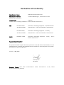
Declaration of Conformity
Manufacturer's Name:
RAD Data Communications Ltd.
Manufacturer's Address:
24 Raoul Wallenberg St., Tel Aviv 69719, Israel
declares that the product:
Product Name:
FCD-E1LC
conforms to the following standard(s) or other normative document(s):
EMC:
Safety:
EN 55022:1998 +
Information technology equipment – Radio disturbance
A1:2000, A2:2003
characteristics – Limits and methods of measurement.
EN 55024:1998 +
Information technology equipment – Immunity
A1:2001, A2:2003
characteristics – Limits and methods of measurement.
EN 60950-1:2001
Information technology equipment – Safety – Part 1:
General requirements.
Supplementary Information:
The product herewith complies with the requirements of the EMC Directive 89/336/EEC, the Low
Voltage Directive 73/23/EEC and the R&TTE Directive 99/5/EC for wired equipment. The product
was tested in a typical configuration.
Tel Aviv, 17 May 2005
Haim Karshen
VP Quality
European Contact: RAD Data
Ottobrunn-Riemerling, Germany
Communications
GmbH,
Otto-Hahn-Str.
28-30,
85521
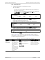
Quick Start Guide
If you are familiar with the FCD-E1LC, use this guide to prepare it for operation,
starting from its factory-default configuration.
1.
Preliminary Preparations
At this stage, do not connect any cables to the FCD-E1LC.
Caution Before performing the preliminary preparation procedures described below,
review the safety precautions given in Section 2.1.
Set all the sections of the rear-panel E1/T1 LOOPBACK switch to OFF.
2.
Connection to Power and Grounding
Any interruption of the protective (grounding) conductor (inside or outside the
device) or disconnecting the protective earth terminal can make the device
dangerous. Intentional interruption is prohibited.
AC power should be supplied to the FCD-E1LC through the 5-foot (1.5m)
standard power cable terminated in a standard 3-prong plug.
The connection of the FCD-E1LC to a DC power source is made by means of a
cable terminated in the AC/DC adapter (AD) plug.
The AC power cord plug must be inserted in an outlet provided with a protective
ground (earth) contact, whereas when using DC power it is necessary to ground
the AD grounding terminal. The protective action must not be negated by use of
an extension cord (power cable) without a protective conductor (grounding).
Caution FCD-E1LC does not have a power on/off switch, and therefore it will start
operating as soon as power is applied. It is recommended to use an external
power on/off switch to control the connection of power to the FCD-E1LC. For
example, the circuit breaker used to protect the supply line to the FCD-E1LC may
also serve as the on/off switch.
FCD-E1LC Ver. 1.0
Cable Connections
1
Quick Start Guide
Installation and Operation Manual
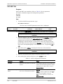
3.
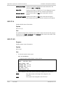
Cable Connections
Refer to the site installation plan, and connect the prescribed cables to the
FCD-E1LC ports:
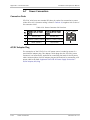
Note
Cable
Connect to …
Main link cable
E1/T1 MAIN connector
Sub link cable (optional)
E1/T1 SUB connector
Data channel 1 cable
CH1 connector
Data channel 2 cable (optional)
CH2 connector
Ethernet cable
10/100BASE-T connector
When using adapter cables for the data channels, first connect the adapter cable
to the data channel connector, and then connect the user’s data cable to the
adapter connector.
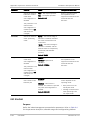
When ready, apply power to the FCD-E1LC.
4.
Configuration Using a Supervisory Terminal
Starting a Preliminary Configuration Session
1. Connect a terminal to the CONTROL DCE port on the FCD-E1LC rear panel (use
a straight cable).
You may use any standard ASCII terminal (dumb terminal or personal
computer emulating an ASCII terminal) equipped with an RS-232
communication interface. Make sure to use VT-100 terminal emulation.
2. Configure the terminal for 19.2 kbps, one start bit, eight data bits, no parity,
and one stop bit. Select the full-duplex mode, echo off, and disable any type
of flow control.
3. Connect the FCD-E1LC to power.
4. Press the <Enter> key several times in sequence: you should see the
FCD-E1LC prompt, FCD>.
If you see PASSWORD> and the FCD-E1LC default password has not yet been
changed, type 1234 and then press <Enter> to obtain the prompt. If your
password is accepted, you will see the FCD-E1LC prompt.
Note
2
If you cannot establish communication with the FCD-E1LC, reset FCD-E1LC
CONTROL DCE port parameters to the factory defaults using the internal switch
SW2 using the procedure described in Chapter 2.
Configuration Using a Supervisory Terminal
FCD-E1LC Ver. 1.0
Installation and Operation Manual
Quick Start Guide
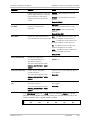
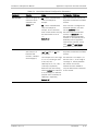
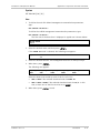
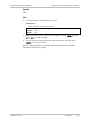
Configuration Procedure
Perform the following actions in the order given below.
Step
Action
Use the Command
1
Reset the database to the default parameters
INIT DB
2
Define the terminal control codes
DEF TERM
3
Configure the supervisory port
DEF SP
DEF CALL
4
Set FCD-E1LC system time and date
TIME
DATE
5
Configure management access and system parameters
DEF
DEF
DEF
DEF
6
Configure the main link parameters
DEF ML
7
Configure the sub link parameters (optional)
DEF SL
8
Configure the data channel parameters
DEF CH 1
DEF CH 2 (when installed)
9
Configure system timing
DEF SYS
10
Define the general system parameters
DEF NAME
DEF NODE
DEF PWD
11
Define the alarm handling parameters
DEF AR
DEF ALM MASK
SYS
AGENT
MANAGER LIST
ROUTE
FCD-E1LC is now ready for operation.
FCD-E1LC Ver. 1.0
Configuration Using a Supervisory Terminal
3
Quick Start Guide
4
Configuration Using a Supervisory Terminal
Installation and Operation Manual
FCD-E1LC Ver. 1.0
Contents
Chapter 1. Introduction
1.1
1.2
1.3
1.4
1.5
1.6
1.7
Overview.................................................................................................................... 1-1
Purpose .................................................................................................................. 1-1
Product Types ......................................................................................................... 1-1
Main Features ......................................................................................................... 1-2
Typical Applications .................................................................................................... 1-3
Physical Description ................................................................................................... 1-4
Functional Description................................................................................................ 1-5
Functional Block Diagram ........................................................................................ 1-5
Internal Bus Functions ............................................................................................ 1-7
Main Link Interface ................................................................................................. 1-8
Sublink Interface ..................................................................................................... 1-9
Synchronous Data Channels .................................................................................. 1-10
Asynchronous Data Channel RS-232/V.24 ............................................................. 1-11
Ethernet Interface ................................................................................................ 1-11
Timing .................................................................................................................. 1-13
Diagnostics ........................................................................................................... 1-15
Timeslot Handling ................................................................................................. 1-16
Management Subsystem ....................................................................................... 1-16
Power Supply Subsystem ...................................................................................... 1-18
Timing Considerations .............................................................................................. 1-19
Main Link Timing Application ................................................................................. 1-19
Data Channel Timing Application ........................................................................... 1-19
System Management Considerations ........................................................................ 1-20
System Management Method ................................................................................ 1-20
Management Access Options ................................................................................ 1-21
Technical Specifications............................................................................................ 1-24
Chapter 2. Installation and Setup
2.1
2.2
2.3
2.4
2.5
2.6
2.7
Introduction ............................................................................................................... 2-1
Scope ..................................................................................................................... 2-1
Safety Precautions .................................................................................................. 2-1
Site Requirements and Prerequisites .......................................................................... 2-3
Physical Requirements ............................................................................................ 2-3
Power Requirements ............................................................................................... 2-3
Connections ........................................................................................................... 2-3
Front and Rear Panel Clearance ............................................................................... 2-5
Ambient Requirements ........................................................................................... 2-5
Package Contents ...................................................................................................... 2-5
Equipment Needed..................................................................................................... 2-6
FCD-E1LC Enclosures .................................................................................................. 2-6
FCD-E1LC Front Panel.............................................................................................. 2-6
FCD-E1LC Rear Panels ............................................................................................. 2-7
Setting the Internal Jumpers and Switches ................................................................ 2-10
Opening the Unit .................................................................................................. 2-10
Closing the Unit .................................................................................................... 2-14
Installing FCD-E1LC in a Rack ................................................................................. 2-15
Connecting the Cables.............................................................................................. 2-15
FCD-E1LC Ver. 1.0
i
Table of Contents
2.8
Installation and Operation Manual
Connecting the Main Link ...................................................................................... 2-15
Connecting the Sublink ......................................................................................... 2-16
Connecting the Data Channels .............................................................................. 2-16
Connecting Ethernet ............................................................................................. 2-16
Connecting the CONTROL DCE Port ....................................................................... 2-17
Connecting to Power ................................................................................................ 2-17
Chapter 3. Operation
3.1
3.2
3.3
3.4
Turning On the Unit ................................................................................................... 3-1
Indicators .................................................................................................................. 3-2
Front Panel Indications ........................................................................................... 3-2
Ethernet Interface Status Indications ...................................................................... 3-2
Configuration and Management Alternatives .............................................................. 3-3
Preliminary Configuration ........................................................................................ 3-3
System Configuration.............................................................................................. 3-3
Routine Management .............................................................................................. 3-4
Supervisory Terminal Characteristics ........................................................................ 3-4
Telnet (IP) Host Characteristics ............................................................................... 3-7
Connections for SNMP Management........................................................................ 3-7
Turning Off the Unit ................................................................................................... 3-7
Chapter 4. Configuration
4.1
4.2
Configuring for Management ...................................................................................... 4-1
Configuring the Supervision Terminal ...................................................................... 4-1
Starting a Control Session ....................................................................................... 4-2
Preliminary Configuration ........................................................................................ 4-3
Configuring for Telnet or SNMP Management .......................................................... 4-4
Ending the Control Session ..................................................................................... 4-5
FCD-E1LC Command Language ................................................................................... 4-5
Command Syntax .................................................................................................... 4-5
What to Do If … ...................................................................................................... 4-6
Ending a Control Session......................................................................................... 4-7
Command Options .................................................................................................. 4-8
Index of Commands ................................................................................................ 4-8
Chapter 5. Configuring FCD-E1LC for a Typical Application
5.1
5.2
Typical Configuration Procedures ................................................................................ 5-1
Outline of General Configuration Procedure ............................................................ 5-1
Configuration Example ............................................................................................... 5-2
Configuring the Local FCD-E1LC ............................................................................... 5-3
Configuring the Remote FCD-E1LC........................................................................... 5-6
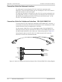
Appendix A. Connection Data
Appendix B. SNMP Management
Appendix C. Operating Environment
Appendix D. Supervision Terminal Commands
ii
FCD-E1LC Ver. 1.0
Chapter 1
Introduction
1.1
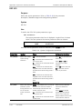
Overview
Purpose
The FCD-E1LC is a managed access unit for business applications that integrates
voice and data traffic over E1 (2.048 Mbps) and fractional E1 services. FCD-E1LC
supports advanced management capabilities, including SNMP.
Product Options
The basic FCD-E1LC is offered with the following payload-carrying ports:
•
E1 main link. This port has an ITU-T Rec. G.703 copper interface that can be
directly connected to E1/fractional E1 networks. The main link interface type
(balanced or unbalanced) is automatically selected in accordance with the
cable connected to the port (to support automatic selection, RAD offers a
special adapter cable). The interface operating mode, DSU or LTU, is
software-selectable. The integral LTU provides a range of up to 2 km.
•
User channel 1. The FCD-E1LC is offered with a synchronous high-speed data
channel. This data channel can operate at rates of n×64 kbps or n×56 kbps,
where n is up to 31. The synchronous data channel can be ordered with
RS-530, V.35, V.36, or X.21 interface. The V.35, V.36 and X.21 interfaces are
supported by means of adapter cables.
FCD-E1LC can also accept a 2048 kbps data stream from a data channel and
convert it to an ITU-T Rec. G.703 unframed signal for transport over the E1
main link, and thus it can also serve as an interface converter and
high-speed, short distance modem.
In addition to the ports available on the basic FCD-E1LC unit, the following
additional payload-carrying ports can be ordered:
FCD-E1LC Ver. 1.0
•
E1 sublink. This port has characteristics similar to those of the main link port,
and it enables chaining of FCD-E1LC units, drop-&-insert, connection of
fractional E1 equipment, connection of a PBX with E1 trunk, etc.
•
User channel 2. The FCD-E1LC also supports a second, optional user channel.
This channel can be ordered with one of the following interfaces:
Synchronous high-speed data channel with characteristics similar to those of
channel 1.
Asynchronous channel with a V.24 interface.
Overview
1-1
Chapter 1 Introduction
Installation and Operation Manual
10/100BaseT Ethernet bridge with VLAN support, for direct connection to
LANs.
Both optional ports can be added to the same FCD-E1LC unit.
Note
In this manual, the generic term FCD-E1LC is used when the information is
applicable to all the FCD-E1LC versions. Information applicable to a specific
version is explicitly identified.
Main Features
The FCD-E1LC main and sublink interfaces are compatible with virtually all
carrier-provided E1 services, meeting all the applicable requirements of
ITU-T Rec. G.823, G.703, G.704, G.706 and G.732. The interfaces support either
2 or 16 frames per multiframe, with or without CRC-4. Line code is HDB3.
Timeslot assignment is programmable, allowing data from each user port to be
placed into user-selectable timeslots.
FCD-E1LC supports various timing modes, to meet the specific requirements of
user’s applications and enable hierarchical dissemination of timing within the
network. Its nodal timing can be locked to:
•
The clock signal recovered from the main link
•
The optional sublink
•
The receive clock of a serial data channel.
Alternatively, an internal oscillator can provide the timing.
FCD-E1LC operation can be controlled and monitored by means of supervision
terminals, Telnet hosts, and SNMP management stations. The management
communication can be either out-of-band, e.g., via connections to the FCD-E1LC
serial management port (either directly or through modem links), or inband with
the management traffic carried by the main link. These capabilities ensure that
FCD-E1LC units can be fully managed from one or more remote locations, in
accordance with the specific requirements of the using organization.
FCD-E1LC has a universal power supply that can operate on a wide range of AC
and DC power sources, including 100 to 240 VAC, 50/60 Hz and -48/-60 VDC, and
has low power consumption.
The FCD-E1LC is available as a standalone unit, intended for installation on
desktops or walls. An optional rack mount adapter kit enables installing one or
two FCD-E1LC units in a 19-inch rack, occupying only 1U.
1-2
Typical Applications
FCD-E1LC Ver. 1.0
Installation and Operation Manual
1.2
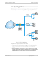
Chapter 1 Introduction
Typical Applications
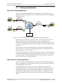
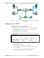
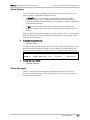
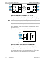
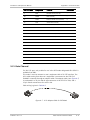
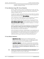
FCD-E1LC units are used to extend various types of data services over a Fractional
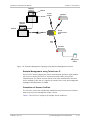
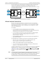
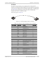
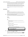
E1 network. Figure 1-1 illustrates the applications supported by FCD-E1LC units.
Router
n x 64 kbps
FCD-E1LC
LAN
Router
ADM
E1
Network
E1
DXC
FCD-E1LC
n x 64 kbps
n x 64 kbps
Router
NMS
FE1
Sub Link
LAN
PBX
FCD-E1LC
Data Channel
n x 64 kbps
V.24
V.35
Router
V.36
X.21
Figure 1-1. FCD-E1LC Applications
The applications supported by the FCD-E1LC include:
FCD-E1LC Ver. 1.0
•
Connection of user’s data equipment through the E1 transport network to a
router or communication front-end that provides access to additional
services.
•
When more than one data connection is required, the FCD-E1LC unit can be
equipped with a second synchronous data channel that can be independently
assigned timeslots on the main link, for connection to other equipment.
Typical Applications
1-3
Chapter 1 Introduction
Installation and Operation Manual
•
FCD-E1LC units with the optional sublink can be used to interconnect other
equipment with fractional E1 interface (for example, a local digital PBX
equipped with an E1 trunk can be connected to the PBX at the main office)
•
The FCD-E1LC also provides Layer 2 (Ethernet bridge) services between a
remote LAN, for example, at a branch office, and the main office LAN. The
user can configure the FCD-E1LC to operate either as a LAN
extender/repeater that transparently transfers all the traffic on the local LAN
to the remote LAN, or as a remote bridge that filters the LAN traffic and
blocks traffic addressed to local stations. The FCD-E1LC bridge supports
VLANs and quality-of-service features.
The user can select the main link bandwidth allocated to each type of traffic in
accordance with the desired throughput.
1.3
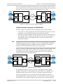
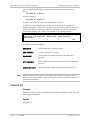
Physical Description
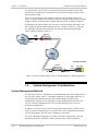
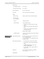
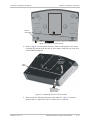
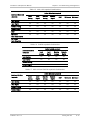
Figure 1-2 shows a general view of a typical FCD-E1LC unit. FCD-E1LC is a
compact standalone unit, intended for installation on desktops or shelves. Unit
height is only 1U (1.75"). An optional rack-mount adapter kit enables the
installation of one or two FCD-E1LC units (side by side) in a 19-inch rack.
FCD-E1LC is cooled by free air convection, and does not include internal fans. The
FCD-E1LC front panel includes only indicators that indicate its status.
Figure 1-2. FCD-E1LC, General View
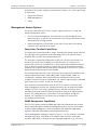
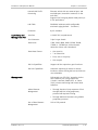
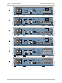
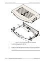
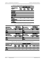
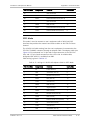
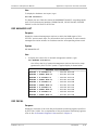
All the connections are made to connectors located on the rear panel. Two typical
rear panels are shown in Figure 1-3 (your panel may look different, depending on
the ordered options). The rear panel includes the following connectors:
•
POWER connector – for connection to the power source (AC or DC)
•
MAIN connector – for the FCD-E1LC main link connection
•
SUB connector (optional) – for connection to the FCD-E1LC sublink
•
CONTROL DCE connector – for connection to the serial supervisory port
•
CH.1 connector – for connection to the channel 1 serial data port
•
CH.2 connector (optional) – for connection to the channel 2 serial data port
or
1-4
Physical Description
FCD-E1LC Ver. 1.0
Installation and Operation Manual
Chapter 1 Introduction
CH.2 LAN connector (optional) – for connection to the 10/100Base-T
Ethernet port.
100 240 VAC /
48 / 60 VDC
CH. 2
E1 / T1
SUB
MAIN
E1 / T1
LOOPBACK
SUB MAIN
CONTROL
10 / 100BASE-T
LINK
ACT
100M
ON
LR L R
RETURN
100 240 VAC /
POWER
DCE
CH. 1
48 / 60 VDC
E1 / T1
SUB
MAIN
E1 / T1
LOOPBACK
SUB MAIN
CONTROL
CH. 2
DCE
CH. 1
ON
L R L R
RETURN
POWER
Figure 1-3. Typical FCD-E1LC Rear Panels
1.4
Functional Description
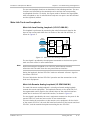
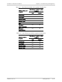
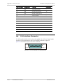
Functional Block Diagram
Figure 1-4 shows the functional block diagram of the FCD-E1LC system.
FCD-E1LC Ver. 1.0
Functional Description
1-5
Chapter 1 Introduction
Installation and Operation Manual
FCD-E1LC
Channel 2 (Optional)
Data Channel
or Ethernet
Ch.2
Channel 1
Ch.1
Data Port
TSER
RSER
Data Channel
Sub Link (Optional)
Framer
LIU
E1/T1
SUB
LIU
E1/T1
MAIN
Main Link
Timing
Subsystem
Data Bus
Address Bus
TDM Bus
Clock Bus
Framer
Test
Subsystem
Inband
Management
Interface
Serial Port
Interface
CONTROL DCE
Connector
Power
Supply
Input Power
Connector
Management
Subsystem
Internal
Voltages
Test Switch
Figure 1-4. FCD-E1LC Functional Block Diagram
FCD-E1LC includes several main subsystems:
1-6
•
Internal buses
•
Main link interface
•
Sublink interface
Functional Description
FCD-E1LC Ver. 1.0
Installation and Operation Manual
Chapter 1 Introduction
•
User interface subsystem (data channels with serial interfaces and Ethernet
port)
•
Timing subsystem
•
Test subsystem
•
Management subsystem
•
Power supply subsystem.
The characteristics of the various subsystems are explained below.
Internal Bus Functions
The FCD-E1LC system performs its various functions by controlling the flow of
data among the various user, sub and main link interfaces in accordance with the
application requirements.
The flow of data is performed through the FCD-E1LC buses, as shown in
Figure 1-4. FCD-E1LC comprises several buses:
•
TDM bus, which carries the data to the main link. The TDM bus serves as a
highway through which all the information processed by the FCD-E1LC flows.
The information is deposited and collected in discrete time intervals, called
timeslots (one timeslot supports a data rate of 64 kbps – see Appendix C). The
TDM bus consists of two lines:
TSER line – carries the transmit data to the main link interface. The other
interfaces deposit data on this line, in the timeslots specified by the
management subsystem.
RSER line – carries the data received by the main link interface. The other
interfaces read their data from the timeslots specified by the
management subsystem.
Each FCD-E1LC port deposits payload information received through its
external interface on one TDM bus line, and simultaneously collects the
information to be sent through the external interface from the other line.
Therefore, considerable flexibility is available with respect to routing, because
each port has access to all the payload information, and can be instructed by
the management subsystem to read and write the desired information in the
desired timeslots of the FCD-E1LC TDM bus.
FCD-E1LC Ver. 1.0
•
Clock bus, which carries the various clock signals used by the FCD-E1LC
system. The FCD-E1LC can lock its system (nodal) clock to various clock
signals applied to its ports, in accordance with the application requirements.
•
Two management buses:
Address bus – carries routing information from the management
subsystem to the other subsystems.
Data bus – carries the internal management data.
Functional Description
1-7
Chapter 1 Introduction
Installation and Operation Manual
Main Link Interface
The main link interface includes a framer and an LIU (line interface unit). The
characteristics and the main functions of the main link interface are described
below.
Main Link Interface Characteristics
The FCD-E1LC main link meets the applicable requirements of ITU-T Rec. G.703,
G.704, G.706, G.732, G.823 and G.826.
The main link port is terminated in an RJ-45 eight-pin connector that supports
two interfaces: 120Ω balanced line interface and 75Ω unbalanced interface.
Normally, the main link uses the balanced interface; to use the unbalanced
interface, all that is needed is to connect the appropriate RJ-45-to-BNC adapter
cable, CBL-RJ45/2BNC/E1/X (offered by RAD). In this case, the interface is
automatically changed and the user’s equipment can be connected to standard
BNC female connectors at the free end of the adapter cable.
The line code is HDB3. The operating mode of the main link interface, DSU or LTU,
is user-selectable. In the DSU mode, the maximum line attenuation is up to 10 dB;
in the LTU mode, the maximum line attenuation is up to 36 dB, which for typical
cables translates to a range of up to 2 km. This allows the FCD-E1LC to be placed
at a distance of up to 2 km.
The interface supports both G732N framing (2 per multiframe) and G732S
framing (16 frames per multiframe, also called timeslot 16 multiframes), in
accordance with ITU-T Rec. G.704 and G.732. The user can also configure the
main link to use the CRC-4 function in accordance with ITU-T Rec. G.704. The use
of the CRC-4 function, as well as the framing mode, is user-selectable.
FCD-E1LC main link can also be operated in an unframed mode, to generate an
ITU-T Rec. G.703 unframed signal. In this mode, FCD-E1LC accepts a 2048 kbps
data stream through a synchronous data channel (or from the optional sublink)
and converts it to an ITU-T Rec. G.703 unframed signal for transport over the E1
main link.
Framer
The transmit path of the framer generates the E1 frame structure transmitted by the
main link port, in accordance with the selected framing mode. The frame structure is
generated by combining the data retrieved from the prescribed timeslots of the TSER
line with the framing overhead, when the main link-framing mode is G732S or
G732N. The TSER line may also carry inband management data generated by the
management subsystem Unused timeslots are filled with a user-selected idle code.
The receive path of the framer extracts the payload data, the inband
management data stream and demultiplexes the incoming E1 data stream.
The framer also collects performance statistics based on framing errors, bipolar
coding violations and errors detected by the CRC-4 monitoring function. These
statistics can be read by the FCD-E1LC management subsystem.
1-8
Functional Description
FCD-E1LC Ver. 1.0
Installation and Operation Manual
Note
Chapter 1 Introduction
When the main link is operated in the unframed mode, the framer is bypassed. In
this mode, the main link transparently transfers the data stream received from
one of the data channels. The appropriate data channel is automatically selected:
channel 1 for an FCD-E1LC with one data channel, and channel 2 for an FCD-E1LC
with two data channels.
Note that when the optional sublink operates in the unframed mode, it is also
automatically bypassed to the main link, but in this case all the other FCD-E1LC
ports are disabled.
Handling of National Bits
FCD-E1LC enables you to control the handling of the national bits, Sa4 through Sa8,
in timeslot 0. You can select the utilization and state of each bit, in accordance
with the following options:
•
Transfer of management traffic: when the inband management traffic is
carried in timeslot 0, the user can select the Sa bits that will carry the traffic.
•
Setting any Sa bit to the desired fixed value, “0” or “1”.
LIU
The transmit path of the LIU includes an HDB3 coder, which converts the NRZ
transmit data stream provided by the E1 framer to the line code specified for use
on E1 links, and then generates the E1 transmit signal in accordance with
ITU-T Rec. G.703.
The receive path of the LIU recovers the received E1 signal and the associated
clock signal. The recovered clock signal is used by other FCD-E1LC circuits, and is
also applied on the clock bus. The recovered E1 signal is decoded by an HDB3
decoder, and sent to the receive path of the E1 framer in NRZ format.
The operating mode of the LIU receive path, DSU or LTU, is user-selectable.
The HDB3 decoder can provide performance statistics for evaluating line
transmission quality even when the CRC-4 option is not used, by collecting data
on the bipolar violations (BPVs) detected in the incoming signal.
Sublink Interface
The optional sublink interface has characteristics similar to that of the main link
interface. The only difference is in wiring: the transmit and receive pairs in the
sublink RJ-45 connector are reversed relative to the main link, thereby enabling
connection of equipment with standard balanced interface by means of a straight
(point-to-point) cable. Therefore, a different adapter cable, CBL-RJ45/2BNC/E1
(also offered by RAD), is needed to use the unbalanced interface.
FCD-E1LC Ver. 1.0
Functional Description
1-9
Chapter 1 Introduction
Installation and Operation Manual
Synchronous Data Channels
Data Channel Interface Characteristics
The FCD-E1LC data channel is available with one of the following types of
interfaces: RS-530, V.35, X.21, or V.36/RS-449. All versions are supplied with a
25-pin D-type female connector.
V.24 interface equipment connects to the RS-232 port of the FCD-E1LC using a
standard straight cable.
All other interface versions are terminated in a 25-pin D-type female connector.
The conversion between the 25-pin channel interface connector and the standard
V.36, V.35, or X.21 interface connectors is made by means of adapter cables:
•
V.36 interface: the adapter cable is terminated in a 37-pin D-type female
connector.
•
V.35 interface: the adapter cable is terminated in a 34-pin female connector.
•
X.21 interface: the adapter cable is terminated in a 15-pin D-type female
connector.
Suitable adapter cables can be ordered from RAD.
The data channel interface supports the following control lines:
•
RTS – input from the local user’s equipment.
•
CTS – output to the local user’s equipment. This line can be configured to be
always in the active state, or track the state of the RTS line.
•
DSR – the DSR line is always active when the FCD-E1LC is powered, except
when a remote loopback is activated on the main link.
•
DCD – the DCD line is active when the FCD-E1LC main link interface is
synchronized.
Data Channel Processing
The data channel operates as a synchronous port, which connects to the TDM
bus via a bus interface. The data channel performs two main functions:
•
In the output (receive) direction, the bus interface reads the payload data
from the appropriate timeslots of the TSER line, under the control of the
management subsystem, and generates a continuous n × 64 kbps or
n × 56 kbps data stream. The data stream is accompanied by a clock signal
derived from the internal FCD-E1LC system clock.
The transmit data and clock signals are then applied to the channel interface,
which provides the interface to the external (user’s) equipment.
•
In the input (transmit) direction, the user’s data applied to the input of the
channel interface is placed in the appropriate timeslots of the RSER line,
under the control of the management subsystem.
To enable synchronous operation, FIFO buffers are used to absorb timing
variations (jitter, wander, etc.). In all the data channel timing modes, the FIFO
1-10
Functional Description
FCD-E1LC Ver. 1.0
Installation and Operation Manual
Chapter 1 Introduction
size is automatically selected in accordance with the data channel rate, as listed
in Table 1-1.
The values listed in Table 1-1 are selected in accordance with the limits specified
in the applicable standards.
In addition, when using the DTE2 mode, the FIFO size can also be manually
selected, to enable the user to increase FIFO size when the jitter exceeds the
expected limits.
Table 1-1. FIFO Size vs. Data Channel Rate
Data Channel Rate (kbps)
FIFO Size (bits)
64
±16
128 and 192
±30
256 through 512
±52
576 through 1024
±72
1088 through 1792
±52
1856 and 1920
±30
1984
±16
In addition to payload data, the data channel interfaces handle two additional
types of signals:
•
Clock signals. The direction of the clock signals depends on the data channel
timing mode, DCE, DTE1, or DTE2. The timing modes are explained in the
Synchronous Data Channel Timing section on page 1-14.
In the DTE2 mode, the clock signal applied to the transmit input is connected
to the clock bus and can be selected as an FCD-E1LC system timing reference.
•
Handshaking signals. The handshaking signals are used to control the
exchange of signals with the user’s equipment, in accordance with the
protocol applying to the installed data channel interface. The handshaking is
performed under the control of the management subsystem.
The functions of the handshaking signals are explained on page 1-10.
Asynchronous Data Channel RS-232/V.24
This interface allows FCD-E1LC to operate opposite external user equipment at bit
rates 1.2, 2.4, 4.8, 9.6, 19.2, or 38.4 kbps. The data rate of the V.24 port can be
selected between 64 kbps and 128 kbps.
Ethernet Interface
The FCD-E1LC can be ordered with a full-feature Ethernet switch with VLAN
support that provides remote bridge services.
The Ethernet switch has a 10/100BaseT interface terminated in a shielded RJ-45
connector for direct connection to LANs.
FCD-E1LC Ver. 1.0
Functional Description
1-11
Chapter 1 Introduction
Installation and Operation Manual
Ethernet Port Interface Characteristics
The Ethernet port 10/100Base-T LAN interface supports auto-negotiation.
However, the user can also disable auto-negotiation and specify directly the
operating rate (10 or 100 Mbps) and operating mode (half-duplex or full-duplex).
The auto-negotiation process uses a standard protocol that permits intelligent
10/100BaseT Ethernet ports to automatically select the mode providing the
highest possible traffic handling capability. Therefore, when auto-negotiation is
enabled, the Ethernet port automatically selects the appropriate operating mode
as soon as it is connected to a LAN or to another Ethernet port.
The following additional capabilities are also available:
•
Automatic detection and correction of MDI/MDIX crossover and polarity,
which enables connecting the FCD-E1LC Ethernet port to any other port
(station or hub) by any type of cable (straight or cross-wired)
•
Use of 802.3 flow control in the full-duplex mode and backpressure flow
control in the half-duplex mode.
The timing mode of the Ethernet channel interface is always DCE (that is, within
the FCD-E1LC the timing of the receive and transmit Ethernet channel paths is
always locked to the FCD-E1LC system clock).
Ethernet Switch Description
The FCD-E1LC includes an Ethernet switch with VLAN support that fully complies
with the IEEE 802.3/Ethernet V.2 standards, has user-selectable forwarding
algorithms, and provides extensive support for QoS features.
The Ethernet switch has two ports:
•
An external port connected to the Ethernet (LAN) interface of the FCD-E1LC,
supported by a MAC controller that performs all the functions required by the
IEEE 802.3 protocol.
•
An internal port connected to the main link interface of the FCD-E1LC, which
can be assigned timeslots in accordance with the desired throughput. This
port supports the HDLC protocol.
The frames passed by the MAC controller are transferred to an internal queue
controller, which controls the frame egress priorities and inserts them in two
separate queues.
Flow Control Options
The user can enable flow control. Flow control is available in both the half-duplex
and full-duplex modes:
•
1-12
In the half-duplex mode, flow control uses a collision-based scheme to
throttle the connected stations when the free buffer space of the FCD-E1LC
Ethernet port is too low, to avoid discarding frames during congestion (this
approach is called back pressure). When the buffer space of the port is
almost full, its MAC controller forces a collision in the input port when an
incoming frame is sensed (the alternative, without flow control, is to discard
the incoming frame).
Functional Description
FCD-E1LC Ver. 1.0
Installation and Operation Manual
•
Chapter 1 Introduction
In the full-duplex mode, the standard flow control method defined in IEEE
802.3x is used. This method is based on pause frames and enables stopping
and restoring the transmission from the remote node. However, this method
can only be used when auto-negotiation is enabled on the port, and the node
attached to the port supports pause frames.
Forwarding Algorithms
The Ethernet switch operates as a MAC bridge that automatically learns the MAC
addresses located on the local LAN.
The Ethernet switch LAN table can store up to 2048 MAC addresses. Only active
MAC addresses are actually stored: after a user-defined aging interval, inactive
addresses are removed from the switch memory.
VLAN and QoS Support
The Ethernet switch can use the priority information carried in the VLAN tag or
the type of service (ToS) precedence for frames carrying IP packets to select the
priority with which traffic will be forwarded:
•
If the frame is tagged, the switch uses the priority value carried by the VLAN
tag to determine the output queue to which the frame is transferred
•
If the frame is not tagged but carries an IP packet, the switch uses the
precedence value carried in the ToS field to determine the output queue to
which the frame is transferred
•
Other untagged frames are transferred to the low-priority queue.
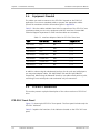
Table 1-2 lists the queuing priorities.
Table 1-2. Output Queuing Priorities
Priority in VLAN Tag
(Tagged Frames)
Precedence in ToS Filed
(Untagged Frames)
Output Queue
7, 6, 5, 4
7, 6, 5, 4
High priority
3, 2, 1, 0
3, 2, 1, 0
Low priority
The switch uses the weighted fair queue scheduling mode: 2:1 weighting is
applied to the two priorities, that is, when the output queues are full, 2 frames
are egressed from the high priority queue for each frame in the low priority
queue. This approach prevents the lower priority frames from being starved out
with only a slightly increased delay to the higher priority frames.
Timing
Multiple clock source selection provides maximum system timing flexibility, and
supports hierarchical dissemination of timing information.
FCD-E1LC Ver. 1.0
Functional Description
1-13
Chapter 1 Introduction
Installation and Operation Manual
System Timing
Internally, the FCD-E1LC uses one timing source (clock). This system clock
determines the transmit timing of the E1 main and sublinks and user channels,
and the timing of most other signal processing operations.
To achieve maximum flexibility in system integration and enable hierarchical
distribution of timing in the system, the FCD-E1LC enables you to select the
source to which the master clock is locked. The available options are as follows:
Note
•
Reference source locked to the recovered receive clock of the main link.
•
Reference source locked to the recovered receive clock of the sublink.
•
Reference source locked to an external clock (such as the transmit clock
applied to a data channel using the DTE2 mode).
The DTE2 mode is not available when the data channel uses the X.21 interface.
The Ethernet interface cannot be used as a reference source.
•
System clock source locked to the internal crystal oscillator, which has an
accuracy of ±50 ppm.
In addition to the selection of a master clock source, you can specify a fallback
source, which is automatically selected in case the master source fails. The fail
criteria are loss of the receive signal on the port selected as the master source,
or inactive RTS line on the data channels. The internal oscillator always serves as
a fallback source, which is automatically selected in case the other selected
timing sources fail.
Main Link Timing
FCD-E1LC recovers the main link receive clock signal, and uses it as the timing
source for the receive path. The main link transmit timing source, which is derived
from the main system clock, can be locked to one of the following sources:
•
Recovered receive clock
•
External clock signal derived from one of the synchronous data channels)
•
Sublink recovered receive clock
•
Internal oscillator.
Sublink Timing
FCD-E1LC recovers the sublink receive clock signal, and uses it as the timing
source for the receive path. The sublink transmit timing source is always derived
from the main system clock.
Synchronous Data Channel Timing
The FCD-E1LC data channel has three timing modes:
•
1-14
DCE – transmit and receive clock for the user’s equipment connected to the
data channel are derived from the main system clock.
Functional Description
FCD-E1LC Ver. 1.0
Installation and Operation Manual
Chapter 1 Introduction
•
DTE1 – the data channel sends the receive data accompanied by the receive
clock, derived from the main system clock, to the user’s equipment
connected to the data channel, and accepts user’s data according to the
user’s equipment transmit clock.
•
DTE2 – FCD-E1LC transmits and receives data according to the clock signals
provided by the equipment connected to the data channel. When using this
clocking mode, the main link clock is locked to the clock signal supplied by the
user’s data channel interface. The DTE2 mode is not available on channels
with X.21 interfaces.
FCD-E1LC provides a FIFO buffer for the data channel, to absorb timing
differences. FIFO size is generally automatically selected, however, in the DTE2
timing mode the user can increase the FIFO size beyond the automatically
selected value, to meet specific system requirements.
V.24 Data Channel Timing
The V.24 data channel operates only in the DCE timing mode.
Ethernet Port Timing
The timing of the Ethernet processing circuits is always derived from the main
system clock (“DCE” timing). This port cannot be selected as a timing source.
Diagnostics
FCD-E1LC has comprehensive diagnostics capabilities that include the following
types of loopbacks and tests:
•
•
FCD-E1LC Ver. 1.0
Main link:
Local analog loopback
Remote analog loopback
Local digital loopback
Remote digital loopback
Inband-activated loopback in the desired timeslots (both transmission to
a remote unit, and activation/deactivation in response to an inband
loopback code)
BER testing in the desired timeslots. To provide compatibility with other
BER testing equipment, the user can select the pattern used for the test
from a wide range of patterns, including standard pseudorandom
patterns.
Sublink:
Local analog loopback
Remote analog loopback
Local digital loopback
Remote digital loopback
Functional Description
1-15
Chapter 1 Introduction
•
Installation and Operation Manual
Serial data channels: local and remote loopbacks.
Timeslot Handling
When operating in any of the framed modes, FCD-E1LC allows you to configure
the routing of the individual timeslots for the data channels (including the
Ethernet interface) and for the sublink. The routing can be modified during
system operation, without disrupting the service to users of timeslots that are
not rerouted. FCD-E1LC automatically connects the timeslots in both the receive
and transmit directions.
You can either individually select the main link timeslots in which the user’s data
is to be inserted, or can use the “bundle” routing mode. Timeslots connected to
data channels are always defined as data timeslots.
To help you route timeslots correctly, FCD-E1LC automatically checks the validity of
your inputs, and reports, by means of error messages, inconsistencies and invalid
selections. The conditions reported include:
•
Attempt to allocate to user’s traffic timeslots that must be reserved for
system use: timeslot 16 when G732S multiframes are used, or a timeslot
dedicated to the management traffic between two FCD-E1LC units connected
in a link.
•
Total bandwidth requested exceeds the available main link bandwidth:
Maximum possible – 31 timeslots.
Maximum 30 timeslots when using G732S framing, or G732N framing with
a timeslot dedicated to management.
Maximum 29 timeslots when using G732S framing and a timeslot
dedicated to management.
When a sublink is installed, the available main link bandwidth is reduced by
the number of timeslots configured as the sublink payload.
•
Number of timeslots assigned to the data channel(s) does not match the
number required to support the selected data rate.
Management Subsystem
The management subsystem controls FCD-E1LC operation, in accordance with its
operating software. The management subsystem also includes an SNMP agent,
and a proprietary IP router for SNMP management traffic.
The database management, as well as the other configuration, test and
monitoring activities (equipment status reading, alarm status and history,
activation of test loops, reading of performance statistics, etc.) can be performed
in three ways:
•
1-16
Supervision Terminal − A “dumb” ASCII terminal connected to the RS-232 port
of the FCD-E1LC (or a PC running a terminal emulation program), controlled
by the program stored in the FCD-E1LC, can be used as a supervision
terminal. FCD-E1LC supports both point-to-point and multidrop connections.
Functional Description
FCD-E1LC Ver. 1.0
Installation and Operation Manual
Chapter 1 Introduction
•
SNMP Management − The SNMP management capability enables fully
graphical, user-friendly management using the RADview network
management stations offered by RAD, as well as management by other
SNMP-based management systems.
•
Telnet − Remote management is also possible using the Telnet
communication protocol, which uses TCP/IP communication, without the
SNMP service. Telnet support enables a remote IP host to control the
operation of FCD-E1LC using functions identical to those provided by a
supervision terminal.
The communication between the management system and FCD-E1LC can take
place out-of-band (by connecting to the serial management port) or inband
(through the main link). FCD-E1LC includes a proprietary IP router for
management traffic. This function enables FCD-E1LC to transfer management
traffic generated by, or addressed to, other FCD-E1LC units, and also inband
management traffic addressed to other RAD equipment that operates over E1
links, such as the Megaplex modular TDM E1/T1 multiplexers, DXC multiservice
access nodes, etc.
Dial-In and Dial-Out Capabilities
FCD-E1LC supports dial-in/dial-out operations, which can be used for remote
out-of-band configuration and monitoring (dial-in). For dial-out operation
FCD-E1LC activates the modem to automatically dial a pre-programmed number
whenever an alarm event occurs.
The remote out-of-band configuration, monitoring and sending callout alarm
messages can be done using the ASCII (terminal), PPP or SLIP protocols.
Alarms
FCD-E1LC stores alarms detected during its operation in a buffer that can hold up
to 100 alarms. During regular operation, an alarm indicator on the front panel is
used to notify the local operator that alarm conditions have been detected.
Separate indications are provided for major and minor alarms. The local operator
can then review the contents of the alarm buffer using the supervision terminal,
a Telnet host, or a management station.
The front-panel LED indicators display in real time the status of the main and
sublinks, and alert when test loops are present in the system. FCD-E1LC can also
automatically report alarms to a remote terminal using a dial-up modem. Alarms
causing dial-out activities are user-selectable.
The alarms stored in the FCD-E1LC alarm buffer can be transmitted automatically
through the serial management access port, for display on a supervision terminal;
when SNMP management is used, alarms are also sent to user-selected
management stations as traps.
The CONTROL DCE port can be configured to operate as a dial-out port, for
automatic reporting of alarms to remote locations. The port is intended for
connection to a Hayes™ or Hayes-compatible dial-up modem. You can program
the reporting method in accordance with the following options:
•
FCD-E1LC Ver. 1.0
Always send a report whenever a new alarm condition is detected.
Functional Description
1-17
Chapter 1 Introduction
Installation and Operation Manual
•
Send a report only upon the detection of a major alarm.
•
Reporting disabled (no dial-out function).
When it is necessary to report an alarm condition, FCD-E1LC initiates the call
setup, and then, after the destination answers, sends the complete contents of
the alarm buffer. Following the transmission of the alarm buffer contents,
FCD-E1LC disconnects automatically.
To increase reporting reliability, you can define the number of dialing retries, and
an alternate directory number to be called in case the primary directory number
cannot be reached. If nevertheless the call cannot be established, the full
contents of the buffer will be sent the next time a call is set up.
To expedite the handling of alarms and reduce the information load during
system malfunctions, the system operator can mask alarm conditions, to prevent
continuous reporting of known alarm conditions, e.g., during maintenance
activities.
Statistics Collection
FCD-E1LC collects and stores E1 port statistics in compliance with ITU-T Rec.
G.706, G.826, with local support as per RFC 1406.
These statistics can be retrieved either from the management station (RADview),
or via the supervision terminal.
The management subsystem exchanges information and sends commands
through several ports:
•
The communication with the various internal subsystems of the FCD-E1LC is
performed through the management address and data buses. The subsystem
also controls the front-panel indicators.
•
The communication with the supervision terminal is performed through the
front panel RS-232 serial port interface. This port is used to perform the
initial configuration of the FCD-E1LC, using any standard ASCII (“dumb”)
terminal (or PC running a basic communication or terminal emulation
program). After the initial configuration, the port can be used to control and
monitor FCD-E1LC operation.
•
When inband management is enabled, the management subsystem transmits
and receives management traffic through the E1 main and/or sub port. The
communication with the E1 port is made through the TDM bus.
Power Supply Subsystem
FCD-E1LC has a universal wide-range power supply, which enables operating on
100 to 240 VAC, 50/60 Hz, or -48/-60 VDC.
1-18
Functional Description
FCD-E1LC Ver. 1.0
Installation and Operation Manual
1.5
Chapter 1 Introduction
Timing Considerations
Main Link Timing Application
Figure 1-5 shows a typical application in which FCD-E1LC is operated with the
main link as the timing reference source, and illustrates the flow of timing signals
within the system.
FCD-E1LC
User's DTE
DCE
Timing
ML
Timing
E1
Network
FCD-E1LC
User's DTE
DCE
Timing
FCD-E1LC
User's DTE
DTE1
Timing
Loopback
Timing
ML
Timing
Master Timing
Source
Figure 1-5. Main Link Timing, Flow of Timing Signals in a Typical Application
When using the main link as the timing reference, the data channels must use
DCE timing. However, DTE1 timing can also be used, provided the user’s
equipment connected to the data channels operates with loopback timing, that
is, the user’s equipment must lock its transmit clock to the receive clock provided
by FCD-E1LC.
FIFO buffers are used on the data channels, to absorb small timing variations
(jitter, wander, etc.). FIFO size is automatically selected in accordance with the
data channel rate, as listed in Table 1-1.
The main link timing mode is particularly suitable for FCD-E1LC units connected to
an E1 network which has an accurate master timing source (e.g., PTT or national
network), because it enables locking the timing of the equipment connected to
the FCD-E1LC units to the network timing.
Data Channel Timing Application
Figure 1-6 shows a typical application, which uses the data channel operating in
the DTE2 timing mode, as the timing reference source, and illustrates the flow of
timing signals within the system.
In the application shown in Figure 1-6, the data equipment located on the
customer’s premises uses the FCD-E1LC link to connect to a data network. Since
data networks include accurate timing sources and do not accept data whose
timing deviates significantly from the network timing, it is necessary to ensure
that the equipment located on the customer’s premises uses the data network
timing.
FCD-E1LC Ver. 1.0
Timing Considerations
1-19
Chapter 1 Introduction
Installation and Operation Manual
For this purpose, the FCD-E1LC connected to the data network uses the data
channel as its timing source, and therefore its main link timing is locked to the
data network timing.
The FCD-E1LC located on the customer’s premises uses main link timing. As a
result, its system timing is also locked to the data network timing, and the network
timing is transferred to the data equipment located on the customer’s premises.
To optimize jitter performance, the FIFO size of a data channel operating in the
DTE2 mode can be selected manually (±16 bits, ±30 bits, ±52 bits, or ±72 bits).
The manually selected value cannot be less that the automatically selected
values, which are listed in Table 1-1.
Data
Network
DTE2
Timing
FCD-E1LC
Data
Channel
E1
Network
Customer Premises
FCD-E1LC
Data
Channel
ML Timing
User's DTE
DCE Timing
Figure 1-6. Data Channel Timing, Flow of Timing Signals in a Typical Application
1.6
System Management Considerations
System Management Method
The FCD-E1LC system is designed for unattended operation. The configuration of
the FCD-E1LC system, that is, a complete collection of operating parameters, is
determined by a database stored in non-volatile memory located in the
management subsystem. The database is automatically loaded upon FCD-E1LC
turn-on, thereby enabling the FCD-E1LC to automatically return to its last
operating configuration.
In addition, FCD-E1LC stores a set of factory-default parameters, which can be
used to start the configuration of a new FCD-E1LC unit; the default parameters
can also be loaded in case the user’s database is corrupted.
FCD-E1LC database management, as well as the other configuration, test and
monitoring activities (equipment status reading, alarm status and history,
1-20
System Management Considerations
FCD-E1LC Ver. 1.0
Installation and Operation Manual
Chapter 1 Introduction
activation of test loops, reading of performance statistics, etc.) can be performed
in three ways:
•
Supervision Terminal
•
SNMP Management
•
Telnet.
Management Access Options
The control subsystem of FCD-E1LC systems supports both out-of-band and
inband management access.
•
For out-of-band management, the connection is made through the front
panel serial port, via the SLIP or PPP protocol. The routing is performed with a
RAD proprietary routing protocol.
•
Inband management is performed via the main E1 link, and/or the sublink
(optional). See Appendix B for details.
Supervision Terminal Capabilities
The supervision terminal provides a simple, command-line based human interface.
The terminals can communicate with the managed FCD-E1LC systems via the
CONTROL DCE serial RS-232 communication port.
The serial port is generally configured as a DCE port, for direct connection to a
terminal, but can also be configured as a DTE port when it is necessary to
connect the terminal via a modem link, or a low-speed data multiplexer channel.
Thus, a remote operator located at a central site can perform all the functions
available from a supervision terminal directly connected to the FCD-E1LC system.
Optional password protection is also available.
The communication data rate of the serial port can be selected in accordance with
system requirements (1200, 2400, 4800, 9600, 19200, 38400, 57600, or
115200 bps). Automatic data rate identification (Autobaud function) is also
available. Data word format is configurable: one start bit, eight data bits, selectable
parity (odd, even, or none), and one or two stop bit.
Since continuous communication with the FCD-E1LC system is necessary only
when management activities are actually performed, one terminal can manage
multiple FCD-E1LC units using a polling protocol, with the connection to the
individual units being made by means of multi-drop modems or digital sharing
devices. For polling purposes, each FCD-E1LC can be assigned an eight-bit
address, for a maximum of 255 nodes (the zero address is reserved for
non-polled communication).
SNMP Management Capabilities
The FCD-E1LC system includes an SNMP agent that can communicate out-of-band
and/or inband through the dedicated management router of the FCD-E1LC system.
To permit SNMP management, you must configure and enable the SNMP agent.
Appendix B provides information on the required parameters.
A basic management topology is shown in Figure 1-7. In this example, a network
management station is attached to an Ethernet LAN. A remote access LAN
extender, MBE-RAS/A, is located near the managed equipment (e.g., FCD-E1LC,
FCD-E1LC Ver. 1.0
System Management Considerations
1-21
Chapter 1 Introduction
Installation and Operation Manual
Megaplex-2100, etc.), and its serial ports are connected via cables to the serial
port of the FCD-E1LC CONTROL DCE connector using the SLIP protocol.
The MBE-RAS extender can connect up to 8 FCD-E1LC devices to one
management system.
LAN
To CONTROL
Connectors of
Managed Equipment
. . . . Serial Ports
MBE/RAS/A
Figure 1-7. Basic Management Topology Using Network Management Station Attached to LAN
The dedicated management traffic routers of the FCD-E1LC systems, and of the
other RAD equipment, are able to determine network topology in accordance with
the capabilities of the routing algorithm, without requiring the user to provide a
priori topology information on the network. Moreover, the routing algorithm also
supports automatic switching to an alternate route in case the currently selected
route fails. The dedicated router operates on the inband traffic; you can also
enable the routing of out-of-band traffic.
Combining Inband and Out-of-Band Management Capabilities
The advanced capabilities of the FCD-E1LC SNMP agents allow easy integration of
the FCD-E1LC system in wide-area managed communication systems. Its
capabilities support any practical communication network topology, as illustrated
in the example shown in Figure 1-8.
In Figure 1-8, the network management station attached to the FCD-E1LC system
can manage, using inband communication over the user-selected links, all the
units (another FCD-E1LC unit, and several Megaplex-2100 units), connected to
the remote ends of the corresponding links. Thus, an entire wide-area network
can be managed by means of a network management station connected to any
FCD-E1LC unit (or to any of the other RAD equipment, which supports SNMP
management).
1-22
System Management Considerations
FCD-E1LC Ver. 1.0
Installation and Operation Manual
Megaplex
System 5
Chapter 1 Introduction
SP-DTE
SP-DCE
To other
Systems
FCD-E1LC
Megaplex
System 4
SP-DCE
Remote
Communication
Node
DXC-30
Main
Link
FCD-E1LC
Network
Management
Station
Figure 1-8. Extended Management Topology Using Network Management Stations
Remote Management using Telnet over IP
The FCD-E1LC system supports the Telnet communication protocol, which enables
any IP host to access the FCD-E1LC system supervision facility using TCP/IP
communication. The Telnet user has access to the same command-line interface
that is available to the user of a supervision terminal, but it uses the management
topologies described above for SNMP.
Prevention of Access Conflicts
The FCD-E1LC system has a dedicated mechanism that prevents access conflicts
when more than one management mode is active.
Table 1-3 lists FCD-E1LC response to multiple-access conditions.
FCD-E1LC Ver. 1.0
System Management Considerations
1-23
Chapter 1 Introduction
Installation and Operation Manual
Table 1-3. Handling of Management Access Conflicts
Type of First
Response to Second Access
Access
Telnet Inband
Telnet
Out-of-Band
Supervision
Terminal
Telnet Inband
Message
Ignored
Message
Telnet
Out-of-Band
Message
Ignored
Ignored
Supervision
Terminal
Disconnects
the terminal
Not possible
Ignored
1.7
E1 Main and
Sublinks
Technical Specifications
Compliance
ITU-T Rec. G.703, G.704, G.706, G.732, G.826
Framing
• G732N, 2 frames per multiframe, CRC-4
option disabled
• G732N, 2 frames per multiframe, CRC-4
option enabled
• G732S, 16 frames per multiframe, CRC-4
option disabled
• G732S, 16 frames per multiframe, CRC-4
option enabled
• Unframed
Data Rate
2.048 Mbps (±50ppm)
Line Code
HDB3
Interface Type
Balanced or unbalanced, with automatic
selection in accordance with the connected
cable
Line Impedance
Balanced interface
120Ω
Unbalanced interface
75Ω
Transmit level
1-24
Balanced Interface
±3V ±10%
Unbalanced Interface
±2.37V ±10%
Technical Specifications
FCD-E1LC Ver. 1.0
Installation and Operation Manual
Chapter 1 Introduction
Receive level
LTU (long haul) mode
0 to -36 dB
DSU (short haul) mode
0 to -10 dB
Jitter Performance
Per ITU-T Rec. G.823
Connector
RJ-45 (ISO 10173) 8-pin connector
Timing
Receive timing
Always recovered from received line signal
Transmit timing
(user-selectable)
Internal
±50 ppm oscillator
External timing
User-selectable source:
• Locked to the transmit clock of the data
channel
• Locked to the recovered receive main link
clock
• Locked to the recovered receive clock of
the sublink (optional)
Allowed range: ±50 ppm
Synchronous User
Data Channels
Loopback timing
Locked to the recovered receive clock, allowed
range ±50 ppm
Data Channel Interface
RS-530 (also supports V.35, V.36/RS-449), or
X.21, according to order.
V .35, V.36/RS-449, X.21 supported by means
of adapter cables
Data Channel Connectors
• RS-530 interface: 25-pin D-type female
• V.35 interface: 34-pin female via adapter
cable
• V.36/RS-449 interface: 37-pin D-type
female via adapter cable
• X.21 interface: 15-pin, D-type female via
adapter cable
Data Rates
User-selectable, n×64 kbps or n×56 kbps,
where n equals 1, 2, 3, ....., 31
Timing Modes
FCD-E1LC Ver. 1.0
Technical Specifications
1-25
Chapter 1 Introduction
Installation and Operation Manual
DCE
Receive and transmit clocks to the
synchronous DTE
DTE1
Receive clock to the synchronous device, and
transmit clock from the synchronous device
DTE2
Receive and transmit clock from the
synchronous DCE (not supported with the X.21
interface)
Control Signals
• CTS follows RTS or constantly ON, software
selectable
• DSR constantly ON, except during the
remote main link loopback
• DCD constantly ON, except during loss of
synchronization alarm on main link
Timeslot Assignment
• Sequential timeslots (bundled)
• User-defined
V.24
Asynchronous
User Data Port
Interface
V.24
Connectors
25-pin D-type female
Bit Rates
64 kbps or 128 kbps. Allows operation
opposite external user equipment at bit rates
1.2, 2.4, 4.8, 9.6, 19.2, or 38.4 kbps
Timing Mode
DCE: receive and transmit clocks to the
asynchronous DTE
Control Signals
CTS follows RTS or constantly ON, software
selectable
DSR constantly ON, except during the remote
main link loopback
DCD constantly ON, except during loss of
synchronization alarm on main link
Timeslot allocation
Sequential timeslots (bundled)
User-defined
Ethernet Port
Compatibility
Relevant sections of IEEE 802.3u, 802.3x,
802.1p and 802.3q
Data Rate
• 10BaseT: 10 Mbps
• 100Base-Tx: 100 Mbps
• Auto-negotiation
1-26
Technical Specifications
FCD-E1LC Ver. 1.0
Installation and Operation Manual
Internal LAN Traffic
Processing
Chapter 1 Introduction
Ethernet switch with one external port, and
one WAN port (toward the network, via the
main link).
Supports QoS using tag-based VLAN priority or
IP ToS precedence
Supervisory and
Management Port
LAN Table
2048 MAC addresses with configurable
automatic aging (default – 5 minutes)
Connector
RJ-45, shielded
Interface
V.24/RS-232 (asynchronous)
Port Connector
9-pin D-type female
Data Rates
1200, 2400, 4800, 9600, 19200, 38400,
57600, or 115200 bps, with automatic
detection of data rate (Autobaud)
Data Word Format
• One start bit
• 7 or 8 data bits
• Even, odd, or no parity
• One stop bit
Dial-in Capabilities
Supports all the supervisory port functions
Dial-out Capabilities
Automatic reporting of alarms to remote
locations; alarms causing dial-out activities are
user-selectable
Management
Full control over FCD-E1LC operation via the
DCE CONTROL port, using supervision
(“dumb”) terminal, SNMP (SLIP), or Telnet
(SLIP), remote monitoring and remote data
collection
Inband Remote
Management
• Through timeslot 0 (any sequence of Sa4
through Sa8 bits) using proprietary
protocol with dynamic routing
• Through dedicated timeslot using reliable
proprietary protocol
Out-of-Band Remote
Management
FCD-E1LC Ver. 1.0
SLIP or PPP protocol
Technical Specifications
1-27
Chapter 1 Introduction
Diagnostics
Installation and Operation Manual
Test Loops
• E1 main link local analog loopback
• E1 main link local digital loopback
• E1 main link remote analog loopback
• E1 main link remote digital loopback
• E1 sublink local analog loopback
• E1 sublink local digital loopback
• E1 sublink remote analog loopback
• E1 sublink remote digital loopback
• Data channel local loopback
• Data channel remote loopback
• BER test on selected timeslots of the main
link
• Inband FT1/FE1 code-activated loopback on
the main link
Note: No loopback can be activated for the
Ethernet interface.
Alarms
Statistics Collection
As per ITU-T Rec. G.706, G.826 with local
support as per RFC 4016
Alarm Buffer
Alarm buffer size: 100 alarms. Last 100 alarms
are stored and available for retrieval.
Each alarm is time stamped (internal clock
without battery backup – must be set to
correct time after turn-off or power failure)
Indicators
Front Panel Indicators
PWR – FCD-E1LC is powered (green)
SYNC LOSS LOC MAIN – Loss of local
synchronization alarm on the main link (red)
SYNC LOSS REM MAIN – Loss of remote
synchronization alarm on the main link (red)
SYNC LOSS LOC SUB – Loss of local
synchronization alarm on the sublink (red)
SYNC LOSS REM SUB – Loss of remote
synchronization alarm on the sublink (red)
TST – test active (yellow)
ALM – alarm indication (red)
Rear Panel Ethernet
Interface Indicators
• LINK (green) – LAN link integrity
• ACT (yellow) – LAN data activity
• 100M – operation at 100 Mbps
1-28
Technical Specifications
FCD-E1LC Ver. 1.0
Installation and Operation Manual
Physical
Characteristics
Power
Environment
FCD-E1LC Ver. 1.0
Chapter 1 Introduction
Height
43.7 mm (1.7 in) (1U)
Width
43.2 cm (19 in)
Depth
24.3 cm (9.5 in)
Weight (approx.)
0.9 kg (2.0 lb)
Supply Voltage
AC source
100 to 240 VAC, 50/60 Hz
DC source
-48 VDC or -60 VDC (-40 to -72 VDC)
Power Consumption
5W max.
Operating Temperature
0° to 50°C (32° to 122°F)
Relative Humidity
Up to 90%, non-condensing
Technical Specifications
1-29
Chapter 1 Introduction
1-30
Technical Specifications
Installation and Operation Manual
FCD-E1LC Ver. 1.0
Chapter 2
Installation and Setup
2.1
Introduction
This chapter provides installation instructions for the FCD-E1LC.
The chapter presents the following information:
•
Safety precautions for installation personnel and users
•
Site requirements
•
General description of equipment enclosures, the available interface options,
and the FCD-E1LC panels
•
Mechanical and electrical installation instructions for the FCD-E1LC
•
Operation procedures (including turn-on, normal indications and turn-off).
After installing the system, it is necessary to configure it in accordance with the
specific user's requirements. The preliminary system configuration is performed
by means of a supervision terminal directly connected to the FCD-E1LC
(procedures for using the terminal are given in Chapter 3). The software
necessary for using the terminal is stored in the FCD-E1LC.
After the preliminary configuration and during routine operations, the FCD-E1LC
can also be managed by means of Telnet hosts or SNMP-based network
management stations, e.g., RADview. Refer to the User's Manual of the network
management station for operating instructions; Telnet hosts use the supervision
terminal procedures.
Safety Precautions
No internal settings, adjustment, maintenance, and repairs may be performed by
either the operator or the user; such activities may be performed only by skilled
service personnel who are aware of the hazards involved.
Warning
FCD-E1LC Ver. 1.0
Always observe standard safety precautions during installation, operation, and
maintenance of this product.
Introduction
2-1
Chapter 2 Installation and Setup
Grounding
Note
Installation and Operation Manual
For your protection and to prevent possible damage to equipment when a fault
condition, e.g., a lightning stroke or contact with high-voltage power lines, occurs
on the cables connected to the equipment, the FCD-E1LC unit must be properly
grounded at any time. Any interruption of the protective (grounding) connection
inside or outside the equipment, or the disconnection of the protective ground
terminal can make this equipment dangerous. Intentional interruption is
prohibited.
Before installing the product, review Handling Energized Products at the
beginning of the manual.
Before switching on this equipment and before connecting any other cable, the
protective ground terminal of the FCD-E1LC must be connected to a protective
ground. The grounding connection is made through the power cable. Therefore,
the grounding arrangements depend on the equipment power supply source:
•
AC-powered units: the power cable must always be inserted in a socket
outlet provided with a protective ground contact, and the protective action
must not be negated by use of an extension cord (power cable) without a
protective conductor (grounding).
•
DC-powered units: the power cable is connected to the FCD-E1LC power
connector through an AC/DC Adapter (AD) available from RAD. Make sure to
connect ground to the AD grounding terminal. The protective action must not
be negated by use of an extension cord (power cable) without a protective
conductor (grounding).
Whenever FCD-E1LC units are installed in a rack, make sure that the rack is
properly grounded and connected to a reliable, low-resistance grounding system.
Dangerous voltages may be present on the cables connected to the FCD-E1LC.
Warning
• Never connect cables to an FCD-E1LC unit if it is not properly installed and
grounded.
• Disconnect all the cables connected to the connectors of the FCD-E1LC before
disconnecting the FCD-E1LC power cable.
The FCD-E1LC does not have a power on/off switch; therefore it will start
Caution operating as soon as it is connected to power.
Caution FCD-E1LC contains components sensitive to ESD. To prevent ESD damage, do not
touch the internal components or connectors.
If you are not using a grounded wrist strap, before touching or performing any
internal settings on the FCD-E1LC, it is recommended to discharge the
electrostatic charge of your body by touching the frame of a grounded
equipment unit.
2-2
Introduction
FCD-E1LC Ver. 1.0
Installation and Operation Manual
Chapter 2 Installation and Setup
Whenever feasible, during installation works use standard ESD protection wrist
straps to discharge electrostatic charges. It is also recommended to use garments
and packaging made of antistatic materials or materials that have high resistivity,
yet are not insulators.
It is also important to make sure that other equipment, in particular customer’s
data equipment connected to FCD-E1LC serial data and Ethernet ports, is properly
grounded (connected to the protective, or safety, ground) before attempting to
connect it to the FCD-E1LC.
2.2
Site Requirements and Prerequisites
Physical Requirements
The FCD-E1LC are intended for installation on desktop and shelves. All the
connections are made to the rear panel.
For installation in 19-inch racks, RAD offers a rack mount (RM) kit. An FCD-E1LC
installed with the RM kit occupies a height of 1U. For installation of one or two
units in a 19-inch rack, refer to the Rack Mounting Kit for 19-inch Racks guide
that comes with the RM kit.
Power Requirements
FCD-E1LC has a wide range AC/DC power supply, and therefore can be powered
either by AC or DC sources:
•
AC-powered FCD-E1LC units should be installed within 1.5m (5 feet) of an
easily-accessible grounded AC outlet capable of furnishing 100 to 240 VAC,
50/60 Hz (nominal mains voltage).
•
DC-powered FCD-E1LC units require a -48 VDC or -60 VDC (nominal) power
source.
Caution Reversing the DC supply voltage polarity will not damage the FCD-E1LC, but the
internal protection fuse will not function.
Connections
This section presents general requirements regarding the connections to the
various FCD-E1LC interfaces. Note that your unit cannot include all the interfaces
listed below.
If you need specific information regarding pin allocations in the FCD-E1LC
interface connectors and wiring data for adapter cables, refer to Appendix A.
Main and Sublink Connections
FCD-E1LC main and sub ports support two interfaces: 120Ω balanced interface
for operation over two twisted pairs, and 75Ω unbalanced interface for operation
FCD-E1LC Ver. 1.0
Site Requirements and Prerequisites
2-3
Chapter 2 Installation and Setup
Installation and Operation Manual
over coaxial cables. Both interfaces are terminated in an RJ-45 eight-pin
connector.
At any time, only one interface is active. The selection of the interface is
automatically made, in accordance with the cable connected to the port:
•
Note
The cable used for connecting to equipment with balanced E1 interface
should include only two twisted pairs, one for the transmit path and the
other for the receive path.
One of the contacts in the E1 port connectors is used to sense the connection of
the unbalanced adapter cable (see below). Therefore, do not connect cables with
more than two pairs when you want to use the balanced interface.
•
To connect to equipment with unbalanced E1 interface, it is necessary to
convert the FCD-E1LC RJ-45 connector to the standard pair of BNC female
connectors used for unbalanced E1 interfaces. For this purpose, RAD offers
15 cm long adapter cables: CBL-RJ45/2BNC/E1/X for the main link port and
CBL-RJ45/2BNC/E1 for the sublink port. These cables have one RJ-45 plug for
connection to FCD-E1LC connector and two BNC female connectors at the
other end.
Connecting the cable to the FCD-E1LC main or sublink connector will cause
the corresponding interface to switch to the unbalanced mode.
The FCD-E1LC main and sub interfaces must not be directly connected to
unprotected public telecommunication networks. The connection to such
networks must be made through a network termination unit that provides
separation between the interface conductors and the telecommunication network
conductors in accordance with the applicable local regulations.
Serial Data Port Connections
The serial data ports of FCD-E1LC are terminated in a 25-pin D-type female
connector. The interface type is RS-530 (which also supports X.21), V.36/RS-449,
V.24, or V.35, according to the order.
•
When using the RS-530 or V.24 interface, equipment with RS-530 or,
respectively, V.24 interface can be directly connected to the data channel
connector using standard cables.
•
For the X.21 interface, an adapter cable, terminated in a 15-pin D-type
female connector, is needed.
•
For the V.35 interface, an adapter cable, terminated in a 34-pin female
connector, is needed.
•
For the V.36/RS-449, an adapter cable, terminated in a 37-pin D-type female
connector, is needed.
Ethernet Port Connections
The optional Ethernet port has a 10/100Base-T Ethernet interface terminated in
an RJ-45 connector, designated 10/100BASE-T.
2-4
Site Requirements and Prerequisites
FCD-E1LC Ver. 1.0
Installation and Operation Manual
Chapter 2 Installation and Setup
The port supports automatic MDI/MDIX detection and cross-over, and therefore
can be connected by any type of cable (standard or crossed) to any type of
10/100Base-T Ethernet port (station or hub).
CONTROL DCE Port Connections
The CONTROL DCE supervisory port has a 9-pin D-type female connector with
RS-232 interface.
The interface (DCE or DTE) is software-selectable. The default selection, DCE,
enables direct connection to terminals and management stations; when the
interface is configured as DTE, it is necessary to use a crossed adapter cable.
Front and Rear Panel Clearance
Allow at least 90 cm (36 inches) of frontal clearance for operator access.
Allow at least 10 cm (4 inches) clearance at the rear of the unit for interface
cable connections. However, during installation, replacement, and cable
connections, at least 90 cm (36 inches) is needed.
Ambient Requirements
The ambient operating temperature of the FCD-E1LC is 0 to 50°C (32 to 122°F),
at a relative humidity of up to 90%, non-condensing.
The FCD-E1LC units are cooled by free air convection; therefore, in rack
installations it is necessary to leave sufficient space (at least 1U) above and
below each unit, to enable free airflow.
2.3
Package Contents
The FCD-E1LC package includes the following items:
FCD-E1LC Ver. 1.0
•
FCD-E1LC unit
•
Multiservice Access Devices and Intelligent CLEs CD-ROM
•
AC power cord or AC/DC adapter plug (if ordered)
•
Rack-mount (RM) kit (if ordered)
•
Interface adapter cable(s), in accordance with order.
Package Contents
2-5
Chapter 2 Installation and Setup
2.4
Installation and Operation Manual
Equipment Needed
The cables you need to connect to the FCD-E1LC depend on the FCD-E1LC
application. You can use standard cables or prepare the appropriate cables
yourself in accordance with the information given in Appendix A.
Table 2-1 lists the cables available from RAD for connection of the FCD-E1LC user
synchronous data port to user’s equipment with DTE interfaces. Contact RAD
Technical Support Department if other interface cables are necessary.
Table 2-1. Interface Adapter Cables for FCD-E1LC Data Ports
Cable
User Interface
Clock Mode
Length (m / ft)
CBL-HS2/V/1
V.35
DCE
2/6
CBL-HS2/V/2
V.35
DTE1
2/6
CBL-HS2/V/3
V.35
DTE2
2/6
CBL-HS2/R/1
V.36/RS-449
DCE
2/6
CBL-HS2/R/2
V.36/RS-449
DTE1
2/6
CBL-HS2/R/3
V.36/RS-449
DTE2
2/6
CBL-HS2/X/1
X.21
DCE
2/6
In addition, when using the unbalanced interface for the main and sublink ports,
you may need adapter cables, CBL-RJ45/2BNC/E1/X and CBL-RJ45/2BNC/E1,
respectively. When using the balanced interface, use cables wired point-to-point,
consisting of two twisted pairs and terminated in RJ-45 connectors.
2.5
FCD-E1LC Enclosures
This section presents a physical description of the various versions of FCD-E1LC
units.
FCD-E1LC Front Panel
Figure 2-1 shows typical FCD-E1LC front panels. The front panel includes only the
FCD-E1LC indicators.
Table 2-2 explains the functions of the indicators located on the FCD-E1LC front
panel.
2-6
FCD-E1LC Enclosures
FCD-E1LC Ver. 1.0
Installation and Operation Manual
Chapter 2 Installation and Setup
A. FCD-E1LC without Sublink
B. FCD-E1LC with Sublink
Figure 2-1. Typical FCD-E1LC Front Panels
Table 2-2. FCD-E1LC Front Panel Indicators
Indicator
Function
PWR Indicator (green)
Lights when the FCD-E1LC is powered
TST Indicator (yellow)
Lights when a test is active
ALM Indicator (red)
Flashes to indicate that a major alarm condition is present in the system.
Lights to indicate that the most severe alarm condition present in the system is
a minor alarm
SYNC LOSS – MAIN LOC
Indicator (red)
Lights to indicate local loss of synchronization on the main link
SYNC LOSS – MAIN REM
Indicator (red)
Lights to indicate that a remote loss of synchronization indication has been
received by the main link interface
SYNC LOSS – SUB LOC
Indicator (red)
Lights to indicate local loss of synchronization on the sublink
SYNC LOSS – SUB REM
Indicator (red)
Lights to indicate a remote loss of synchronization indication has been received
by the sublink interface
FCD-E1LC Rear Panels
The components located on the FCD-E1LC rear panels depend on the ordered
interfaces.
Figure 2-2 shows several typical rear panels of FCD-E1LC units. Table 2-3 explains
the functions of the rear panel components.
FCD-E1LC Ver. 1.0
FCD-E1LC Enclosures
2-7
Chapter 2 Installation and Setup
100 240 VAC /
Installation and Operation Manual
48 / 60 VDC
CH. 2
E1 / T1
A.
SUB
MAIN
E1 / T1
LOOPBACK
SUB MAIN
CONTROL
10 / 100BASE-T
LINK
ACT
100M
ON
LR L R
DCE
RETURN
POWER
100 240 VAC /
48 / 60 VDC
CH. 2
E1 / T1
B.
CH. 1
SUB
MAIN
E1 / T1
LOOPBACK
SUB MAIN
CONTROL
10 / 100BASE-T
LINK
ACT
100M
ON
LR L R
DCE
RETURN
POWER
100 240 VAC /
48 / 60 VDC
CH. 2
E1 / T1
C.
CH. 1
SUB
MAIN
E1 / T1
LOOPBACK
SUB MAIN
CONTROL
10 / 100BASE-T
LINK
ACT
100M
ON
LR L R
DCE
RETURN
POWER
100 240 VAC /
48 / 60 VDC
CH. 2
E1 / T1
D.
CH. 1
SUB
MAIN
E1 / T1
LOOPBACK
SUB MAIN
CONTROL
10 / 100BASE-T
LINK
ACT
100M
ON
LR L R
RETURN
POWER
100 240 VAC /
48 / 60 VDC
E1 / T1
E.
SUB
MAIN
E1 / T1
LOOPBACK
SUB MAIN
DCE
CH. 1
CONTROL
CH. 2
DCE
CH. 1
CONTROL
CH. 2
DCE
CH. 1
ON
L R L R
RETURN
POWER
100 240 VAC /
48 / 60 VDC
E1 / T1
F.
SUB
MAIN
E1 / T1
LOOPBACK
SUB MAIN
ON
L R L R
RETURN
POWER
Figure 2-2. Typical FCD-E1LC Rear Panels
2-8
FCD-E1LC Enclosures
FCD-E1LC Ver. 1.0
Installation and Operation Manual
Chapter 2 Installation and Setup
Table 2-3. FCD-E1LC Rear Panel Components
Item
Function
POWER Connector
Power connector, for connection of the supply voltage (either AC or DC)
CH.1 Connector
25-pin D-type female connector, for connection to the channel 1 data port
(interface type depends on ordering option)
CH.2 Connector
25-pin D-type female connector, for connection to the optional channel 2 data
port (interface type depends on ordering option)
CH.2 10/100BASE-T
Connector
RJ-45 connector for connection to the optional Ethernet LAN port, which has a
10/100Base-T interface
CH.2 10/100BASE-T
LINK Indicator
Green indicator located in the CH.2 10/100BASE-T connector:
•
Lights steadily when the LAN port detects the link integrity signal (normal
condition when there is no data activity)
•
Off when the port does not detect the link integrity signal
CH.2 10/100BASE-T
ACT Indicator
Yellow indicator located in the CH.2 10/100BASE-T connector, flashes or lights
when the LAN port transmits or receives data (normal operating condition)
CH.2 10/100BASE-T
100M Indicator
Green indicator for the optional LAN port:
•
Lights steadily when the LAN port operates at a data rate of 100 Mbps
•
Off when the LAN port operates at a data rate of 10 Mbps
E1/T1 MAIN Connector
RJ-45 connector for connection to the main link interface
E1/T1 SUB Connector
RJ-45 connector for connection to the optional sublink interface
CONTROL DCE Connector
9-pin female D-type connector for connection to the FCD-E1LC supervisory
terminal port
E1/T1 LOOPBACK Selector
4-section switch, controls the main and sublink analog test loopbacks. For a
description of the loopbacks, refer to Chapter 4.
Section
Function
SUB L
Controls the sublink analog local loopback.
SUB R
Controls the sublink analog remote loopback.
MAIN L
Controls the main link analog local loopback.
MAIN R
Controls the main link analog remote loopback.
To change the state of a loopback:
•
To activate a loopback using this switch, set the corresponding switch
section to ON. The TST indicator on the front panel will light.
•
To deactivate a loopback, return the switch to OFF. If no other test is active
on the FCD-E1LC, the TST indicator on the front panel will turn-off.
Note that the same activities can be performed by management (for example,
using the supervisory terminal). The actual state of a loopback is therefore
determined by the last command (either from the management or the switch).
FCD-E1LC Ver. 1.0
FCD-E1LC Enclosures
2-9
Chapter 2 Installation and Setup
2.6
Installation and Operation Manual
Setting the Internal Jumpers and Switches
Caution Before starting, review the safety and ESD precautions given in Section 2.1.
The FCD-E1LC preliminary configuration is performed by means of a supervisory
terminal. To protect against unauthorized use, you must enter a password before
you can start using the supervisory terminal.
In case you do not know the password and/or the communication parameters of
the serial supervisory port, it is necessary to restore the default values before
you can start configuration activities.
The FCD-E1LC includes an internal switch (marked SW2 on the FCD-E1LC main
printed circuit board) that controls the loading of the default parameters.
This section presents instructions for reaching the internal switch.
Note
If you can use the supervisory terminal to enter the INIT DB command, you may
skip this section.
It is also recommended to check the settings of the internal switch in case the
configuration data prepared by you is lost after resetting (or turning off and on
again) the FCD-E1LC: usually, this indicates that the FCD-E1LC switch is set to
reload the factory-default parameters upon power-up.
Note
³
For some FCD-E1LC hardware versions, it is not necessary to open the enclosure
to reach the switch: in these versions, the switch is located under the main
printed circuit board and can be accessed by opening a small cover on the bottom
of the FCD-E1LC case.
To reload the default parameters by means of the internal switch:
1. Open the FCD-E1LC enclosure as explained below.
2. Set the INIT_DB section of switch SW2 to ON.
3. Arrange the FCD-E1LC for safe operation with the cover open.
4. Connect power to the FCD-E1LC.
5. Wait about 2 minutes, and then disconnect the power from the FCD-E1LC.
6. Set the INIT_DB section of switch SW2 to OFF.
7. Close the FCD-E1LC cover as explained on page 2-14.
Opening the Unit
³
To open the FCD-E1LC enclosure:
1. Refer to Figure 2-3 and open the screws that fasten the FCD-E1LC cover.
Keep screws in a safe place, for reuse.
2-10
Setting the Internal Jumpers and Switches
FCD-E1LC Ver. 1.0
Installation and Operation Manual
Chapter 2 Installation and Setup
Release
Screws
Figure 2-3. FCD-E1LC Cover Screws
2. Refer to Figure 2-4 and release the cover catches as illustrated in the figure.
If pushing the catches with the nails of your fingers is difficult, you may use a
narrow-blade screwdriver.
Press in this
direction with
your index
finger and...
Cover
Catches
… simultaneously
press upward edge
of bottom cover
with your thumb
Figure 2-4. Releasing FCD-E1LC Cover Catches
3. After catches are released, the cover easily slides off. Figure 2-5 shows a
general view of a typical FCD-E1LC unit after cover is removed.
FCD-E1LC Ver. 1.0
Setting the Internal Jumpers and Switches
2-11
Chapter 2 Installation and Setup
Installation and Operation Manual
Switch
SW2
Figure 2-5. FCD-E1LC, General View After Cover is Removed
³
To check and change internal switch SW2:
1. Refer to Figure 2-6 and identify the location of the SW2 switch.
Note
2-12
In addition to switch SW2 identified in these figures, the FCD-E1LC boards include
additional switches and jumpers that are preset by the manufacturer and must
not be moved.
Setting the Internal Jumpers and Switches
FCD-E1LC Ver. 1.0
Installation and Operation Manual
Chapter 2 Installation and Setup
Not Used (Always OFF)
ON
OFF
SW2
Switch
SW2
Figure 2-6. FCD-E1LC, Location of Switch SW2
2. The functions of SW2 switch sections are explained in Table 2-4. Check and if
necessary change the positions of the various sections in accordance with
your requirements.
Table 2-4. Switch SW2 Functions
Section
INIT_DB
Function
This section selects the source of the configuration database parameters.
FCD-E1LC is delivered with its configuration database loaded with the factory default parameters.
You can select this position again to restart with the default parameters in case the current
values are not known.
ON
FCD-E1LC loads the factory-default parameters upon power-up.
OFF
FCD-E1LC loads the user-selected parameters from its non-volatile memory on power-up.
Default: OFF
Note:
FCD-E1LC Ver. 1.0
User-selected parameter values are not erased by setting the DB INIT section to ON. Only
after FCD-E1LC is turned off and then powered again, do the default values replace the
user values.
Setting the Internal Jumpers and Switches
2-13
Chapter 2 Installation and Setup
Installation and Operation Manual
Table 2-4. Switch SW2 Functions (Cont.)
Section
PSW
Function
FCD-E1LC is delivered with a default password, RAD. However, to prevent unauthorized personnel
from using the FCD-E1LC supervision program, you can use a password of your own.
ON
FCD-E1LC uses the default password.
OFF
FCD-E1LC uses the user-defined password.
Default: OFF
The FCD-E1LC polling address (node number) is also affected by the PSW section: with this
section set at ON, the node number is set to 0. Upon first-time operation, it is recommended to
use the ON position to start the configuration. You can select this position again to restart with
the default password and node address 0 in case the current user password was lost.
Note You can use the DEF SP command to cancel password protection. In this case, no
password is used, irrespective of the position of this switch section.
DEF PAR This section selects the source of the supervisory port parameters.
ON
FCD-E1LC loads the factory-default supervisory port parameters (automatic detection of
any standard data rate in the range of 1200 to 115,200 bps, one start bit, 8 data bits, no
parity, one stop bit, terminal mode).
OFF
Supervisory port operates according to user-defined parameters.
Default: OFF
Note User-selected parameter values are not erased by setting one or more sections of switch
SW2 to ON: this action merely causes FCD-E1LC to use the default values. However, if
FCD-E1LC is powered off and then on again, the default values replace the user values.
Closing the Unit
³
To close FCD-E1LC enclosure:
1. Refer to Figure 2-7, and place cover as shown.
Figure 2-7. Closing the FCD-E1LC Cover
2-14
Setting the Internal Jumpers and Switches
FCD-E1LC Ver. 1.0
Installation and Operation Manual
Chapter 2 Installation and Setup
2. Push cover in the direction shown in Figure 2-7, until you hear the cover
catches click as they lock the cover in place.
3. Refer to Figure 2-3 and fasten the cover with its screws.
Installing FCD-E1LC in a Rack
FCD-E1LC units are intended for installation on desktops, shelves or in 19-inch
racks. Do not connect power to the enclosure before it is installed in the
designated position.
For rack installation, a rack mount (RM) kit, is available from RAD. Refer to the
RM installation leaflet for detailed instructions.
2.7
Connecting the Cables
Before starting, refer to the site installation plan and identify the cables intended
for connection to this FCD-E1LC unit. For general information regarding
connections, refer to Section 2.2.
Connecting the Main Link
³
To connect the FCD-E1LC main link to equipment with balanced interface:
•
Note
³
Use a straight (point-to-point) cable terminated in RJ-45 connectors to
connect the FCD-E1LC RJ-45 connector designated E1/T1 MAIN to the
designated equipment connector.
One of the contacts in the E1 main port connector is used to sense the
connection of the unbalanced adapter cable (see below). Therefore, do not
connect cables with more than two pairs when you want to use the balanced
interface.
To connect the FCD-E1LC main link to equipment with unbalanced interface:
1. Connect the RJ-45 connector of the CBL-RJ45/2BNC/E1/X adapter cable to the
FCD-E1LC RJ-45 connector designated E1/T1 MAIN.
2. Connect the coaxial cables from the other equipment to the two BNC
connectors at the other end of the adapter cable. Pay attention to correct
connection:
FCD-E1LC Ver. 1.0
Connect the cable from the user’s equipment transmit output to the
green BNC connector (main link receive input)
Connect the cable from the user’s equipment receive input to the red BNC
connector (main link transmit output).
Connecting the Cables
2-15
Chapter 2 Installation and Setup
Installation and Operation Manual
Connecting the Sublink
³
To connect equipment with balanced interface to the FCD-E1LC sublink:
•
Note
³
Use a straight (point-to-point) cable terminated in RJ-45 connectors to
connect the designated equipment connector to the FCD-E1LC RJ-45
connector designated E1/T1 SUB.
One of the contacts in the E1 sub port connector is used to sense the connection
of the unbalanced adapter cable (see below). Therefore, do not connect cables
with more than two pairs when you want to use the balanced interface.
To connect equipment with unbalanced interface to the FCD-E1LC sublink:
1. Connect the RJ-45 connector of the CBL-RJ45/2BNC/E1 adapter cable to the
FCD-E1LC RJ-45 connector designated E1/T1 SUB.
2. Connect the coaxial cables from the other equipment to the two BNC
connectors at the other end of the adapter cable. Pay attention to correct
connection:
Connect the cable from the user’s equipment receive output to the green
BNC connector (sublink transmit input)
Connect the cable from the user’s equipment transmit input to the red
BNC connector (sublink receive output).
Connecting the Data Channels
Each serial data port of the FCD-E1LC is terminated in a 25-pin D-type female
connector. The interface type is RS-530 (also supporting X.21) or V.35, according
to order.
The required cables can be prepared in accordance with the port connector wiring
information given in Appendix A, or ordered separately from RAD. See list of
cables available from RAD in Section 2.4.
When using adapter cables, first connect the adapter cable to the FCD-E1LC data
channel connector, and then connect the user’s data cable to the adapter
connector.
Connecting Ethernet
Identify the cable intended for connection to the 10/100Base-T connector.
Connect the cable to the corresponding module connector.
Use a standard (station) cable wired point-to-point for connection to any type of
Ethernet port (hub or station).
2-16
Connecting the Cables
FCD-E1LC Ver. 1.0
Installation and Operation Manual
Chapter 2 Installation and Setup
Connecting the CONTROL DCE Port
The front panel CONTROL DCE supervisory port has a 9-pin D-type female
connector with RS-232 interface. The interface (DCE or DTE) is
software-selectable:
•
When the interface is configured as DCE, enables direct connection to
terminals and management stations
•
When the interface is configured as DTE, it is necessary to use a crossed
adapter cable.
Caution Cables used for the CONTROL DCE port connection must have a frame ground
connection. Use ungrounded cables when connecting a supervisory terminal to a
DC-powered unit with floating ground. Using improper terminal cable may result
in damage to the CONTROL DCE port.
2.8
Connecting to Power
Any interruption of the protective (grounding) conductor (inside or outside the
device) or disconnecting the protective earth terminal can make the device
dangerous. Intentional interruption is prohibited.
Warning
Before switching this FCD-E1LC unit on and before connecting any other cable,
FCD-E1LC protective earth terminals must be connected to protective ground.
This connection is made through the DC or AC power cable. The AC power cord
plug should only be inserted in an outlet provided with a protective ground
(earth) contact, whereas when using DC power it is necessary to ground the AD
grounding terminal. The protective action must not be negated by use of an
extension cord (power cable) without a protective conductor (grounding).
Dangerous voltages may be present on the cables connected to the FCD-E1LC:
• Never connect cables to an FCD-E1LC unit if it is not properly installed and
grounded. This means that its power cable must provide a protective ground
(earth) contact before connecting any user or main link cable to the FCD-E1LC.
• Disconnect all the cables connected to the connectors of the FCD-E1LC before
disconnecting the FCD-E1LC power cable.
Caution FCD-E1LC does not have a power on/off switch, and therefore it will start
operating as soon as power is applied. It is recommended to use an external
power on/off switch to control the connection of power to the FCD-E1LC. For
example, the circuit breaker used to protect the supply line to the FCD-E1LC may
also serve as the on/off switch.
AC power should be supplied to the FCD-E1LC through the 5-foot (1.5m)
standard power cable terminated in a standard 3-prong plug.
The connection of the FCD-E1LC to a DC power source is made by means of a
cable terminated in the AC/DC adapter (AD) plug.
FCD-E1LC Ver. 1.0
Connecting to Power
2-17
Chapter 2 Installation and Setup
³
Installation and Operation Manual
To connect AC power:
1. Connect the AC power cable to the FCD-E1LC power connector.
2. Insert the plug at other end of the AC power cable into a socket (outlet) with
a protective ground contact. If power is connected, the PWR indicator of the
FCD-E1LC will light.
³
To connect DC power:
•
2-18
Refer to the DC power supply connection supplement for instructions how to
wire the DC cables. The DC supplement is provided on the technical
documentation CD supplied with the unit.
Connecting to Power
FCD-E1LC Ver. 1.0
Chapter 3
Operation
3.1
³
Turning On the Unit
To turn on the unit:
1. Before first-time turn-on, check that the installation and the required cable
connections have been correctly performed in accordance with the
instructions given in Chapter 2.
2. Set all the sections on the rear panel E1/T1 LOOPBACK switch to OFF.
3. To enable monitoring the FCD-E1LC during power-up and preliminary
configuration procedures, it is recommended to connect a terminal to the
CONTROL DCE connector of the FCD-E1LC.
Any standard ASCII terminal (dumb terminal or personal computer emulating
an ASCII terminal) equipped with an RS-232 communication interface can be
used to control the FCD-E1LC operation. For best results, use VT-100 terminal
emulation. To monitor the power-up process, configure the terminal for any
rate supported by the FCD-E1LC (1200 to 115200 bps), one start bit, eight
data bits, no parity, and one stop bit. Select the full-duplex mode, echo off,
and disable any type of flow control.
Caution FCD-E1LC does not have a power on/off switch, and therefore it will start
operating as soon as power is applied.
4. Connect power to the FCD-E1LC.
5. The FCD-E1LC PWR indicator turns on; the other indicators turn-on for a start
time, and then turn-off.
6. Wait for the completion of the power-up self-test and initialization. This
takes about one minute.
7. Press <CR> several times in sequence to establish communication with the
FCD-E1LC. The terminal will then display various messages during the
power-up.
A typical display, which notifies you of the results of its power-up self-test is
shown below:
FCD Self Test in Progress ... OK
or
FCD Self Test in Progress ... Failed
In the latter case, you must repair or replace FCD-E1LC before you can
continue using it.
FCD-E1LC Ver. 1.0
Turning On the Unit
3-1
Chapter 3 Operation
Installation and Operation Manual
8. If FCD-E1LC successfully passed the power-up self-test, it sends the following
message:
FCD Supervisory Port On Line. Type ‘H’ For Help
Now FCD-E1LC is ready for operation.
Note
If the configuration data stored by FCD-E1LC is corrupted, FCD-E1LC reports that
the self-test has failed or sends the DATABASE CHECKSUM ERROR alarm
message.
In this case, you will have to load the default configuration. To do this, either
enter the INIT DB command from the terminal or use the internal switch SW2 as
explained in Chapter 2.
3.2
Indicators
Front Panel Indications
Note
For a description of FCD-E1LC front panel indicator functions, see FCD-E1LC Front
Panel on page 2-3 .
As long as the FCD-E1LC is powered, the PWR indicator lights steadily.
During normal operation, the ALM, all the SYNC LOSS, and the TST indicators must
be off.
Any alarm condition causes the ALM indicator to light (for major alarms, it will
flash). Use the supervision terminal to read the alarm messages.
If any of the main link alarm indicators or the TST indicator lights, data transfer is
interrupted.
The TST indicator lights when a test is activated. If the test is activated from the
local FCD-E1LC, see the test type using the supervision terminal (DSP ST CH1,
DSP ST CH2, DSP ST ML or DSP ST SL). You can disconnect a local loop by
means of the CLR LOOP command, as explained in Appendix D.
Ethernet Interface Status Indications
If the FCD-E1LC optional Ethernet port is not yet connected to an active LAN, the
LINK indicator is off.
After the connection is made and the auto-negotiation process is successfully
completed:
3-2
•
The LINK indicator lights steadily
•
The ACT indicator lights steadily or flashes at the rate of the traffic flow
through the FCD-E1LC LAN interface
•
The 100M indicator indicates the actual operating rate: off for 10 Mbps, on
for 100 Mbps.
Indicators
FCD-E1LC Ver. 1.0
Installation and Operation Manual
3.3
•
Chapter 3 Operation
Configuration and Management Alternatives
Before an FCD-E1LC unit can be used in its intended application, it is necessary to
perform two types of activities:
•
Preliminary configuration: its purpose is to prepare the FCD-E1LC unit for
using any of the supported management facilities.
•
System configuration: its purpose is to specify the system operational
parameters needed by the FCD-E1LC to fulfill its intended function in the
user’s environment.
Preliminary Configuration
The preliminary configuration of the FCD-E1LC unit must always be performed
using an ASCII terminal equipped with an RS-232 communication interface,
directly connected to the FCD-E1LC supervisory port (the CONTROL DCE
connector). The ASCII terminal can be a standard “dumb” communication terminal,
or a personal computer running a terminal emulation or communication program.
System Configuration
FCD-E1LC operating mode is determined by a set of parameters stored in the
internal non-volatile memory. To select these parameters, use the FCD-E1LC
supervision terminal.
Note
If you make a configuration error (for example, you select a parameter value that
conflicts with the current operating mode), FCD-E1LC rejects the erroneous
selection and displays an error message that identifies the error.
After the operating parameters have been loaded (a process called
configuration setup), FCD-E1LC no longer requires operator attendance.
The configuration stored in the FCD-E1LC memory is not affected when power is
turned off. Upon turn-on, FCD-E1LC checks the validity of the stored
configuration data, and after the self-test, takes the last selected configuration.
If the configuration does not require modification, FCD-E1LC is ready for
operation immediately after power is applied. However, if the configuration data
is corrupted, FCD-E1LC loads a default configuration prepared by the
manufacturer instead.
After performing the preliminary configuration, you can configure the FCD-E1LC
unit using any of the following options:
FCD-E1LC Ver. 1.0
•
Use the terminal as a supervision terminal, for performing all the
management activities supported by the FCD-E1LC unit.
•
Configure the FCD-E1LC unit from any IP host using the Telnet protocol. After
establishing a Telnet session with the FCD-E1LC unit, the Telnet protocol
offers the same functionality as the supervision terminal, and in addition
enables remote access over IP networks.
Configuration and Management Alternatives
3-3
Chapter 3 Operation
Installation and Operation Manual
Typically, the Telnet host is a PC or a UNIX station with the appropriate suite
of TCP/IP protocols. The host can be directly connected to the managed
FCD-E1LC unit. However, the host may also be located at a remote site, the
only requirement being that IP communication be established between that
site and the managed FCD-E1LC unit (either out-of-band through a separate
network, using the SLIP or PPP protocol, or inband through the main and/or
sublink).
•
Configure the FCD-E1LC unit by means of SNMP-based network management
stations.
Routine Management
During regular operation, the FCD-E1LC unit can be managed using any of the
options listed above for system configuration.
Supervisory Terminal Characteristics
Any standard ASCII terminal (“dumb” terminal or personal computer emulating an
ASCII terminal) equipped with a V.24/RS-232 communication interface can be
used to control FCD-E1LC operation.
Control Port Interface Characteristics
FCD-E1LC has a V.24/RS-232 asynchronous DCE port, designated CONTROL DCE
and terminated in a 9-pin D-type female connector. The control port continuously
monitors the incoming data stream and will immediately respond to any input
string received through this port. Moreover, when the FCD-E1LC control port is
configured to support the SLIP or PPP protocol, messages in each of the
supported protocols are automatically identified and processed.
The supervisory terminal can be connected to the FCD-E1LC control port either
directly, or through a modem or any other type of full-duplex data link:
•
For direct connection to the control port, use a straight-through cable.
•
For connection to the control port through a modem or data link, use a
cross-cable (also called null modem cable).
FCD-E1LC can communicate with the supervision terminal or modem at rates of
1200, 2400, 4800, 9600, 19200, 38400, 57600, or 115200 bps. The word
format consists of one start bit, 8 data bits, and one or two stop bits. Parity can
be odd, even or disabled.
Always make sure the communication interfaces of the terminal/modem and the
FCD-E1LC are configured for operation with the same parameters.
Modems
The CONTROL DCE port also supports the connection of a remote supervision
terminal through a modem or low-speed data link: in this case, configure the
control port interface as DTE and use a cross-cable (also called null modem cable)
to connect to the CONTROL DCE port.
3-4
Configuration and Management Alternatives
FCD-E1LC Ver. 1.0
Installation and Operation Manual
Chapter 3 Operation
FCD-E1LC supports two types of modems:
•
Dial-up Hayes™ compatible modems. FCD-E1LC has call-in and call-out
capabilities; that is, it can accept external calls and initiate calls in order to
report alarms.
•
Multidrop modems, such as the RAD SRM-8 miniature multidrop modem. The
multidrop configuration can be used to connect the supervisory ports of
several FCD-E1LC units located in close proximity to a common supervision
terminal, using multidrop modems (or digital sharing devices): these devices
enable to connect a single terminal to many FCD-E1LC units.
For multidrop operation, each FCD-E1LC unit must be assigned a node
address in the range of 1 through 255.
Note
FCD-E1LC units also support address 0: assigning address 0 to an FCD-E1LC unit
means that it will accept and answer any message: this is not permitted in
multidrop operation. Address 0 is however recommended for use both with direct
connections, and point-to-point or dial-up modem links.
Control Port Handshaking Protocol with Supervision Terminals
The handshaking between the FCD-E1LC and the supervision terminal uses the
control lines in the CONTROL DCE supervisory port connector. Since the interface
mode is selected by software, the direction of the interface signals is the same in
both the DCE and DTE mode, and a cross-cable is required for the DTE mode.
The control lines in DCE and DTE modes and the direction of the control signals
are detailed in Table 3-1.
Table 3-1. Control Port Handshaking Protocol
Control
Line
CTS
DCD
Interface Type
DCE
Out
Out
Function
DTE
Not Used
Out
Clear to Send line. The state of the CTS line is determined by
user’s configuration:
•
ON – The CTS line is always ON (active).
•
=RTS – The CTS line follows the RTS line.
Data Carrier Detect line. The state of the DCD line depends on the
communication address (node number):
•
When the node address is 0, the DCD line is always ON (active).
•
When a non-zero node address is used, the DCD line becomes ON
(active) when data is detected on the RD line, provided the
FCD-E1LC recognizes its own address in the data stream.
To simulate DTE operation, the delay between these events can be set
by the user (by means of the DCD DELAY parameter).
FCD-E1LC Ver. 1.0
Configuration and Management Alternatives
3-5
Chapter 3 Operation
Interface Type
Control
Line
DSR
Installation and Operation Manual
DCE
Function
DTE
Out
Out
Data Set Ready line. The state of the DSR line is user-configurable.
•
Usually, the DSR line is configured to track the DTR line. In this case,
if the control port interface is DTE, the DSR line will be set to ON for
five seconds when the RI line is ON while the DTR line is OFF.
•
If the control port interface is DCE, the DSR line can also be
configured to be continuously ON. However, if the DTR line switches
to OFF, the DSR line will also switch to OFF for 5 seconds.
In addition, FCD-E1LC always sets DSR OFF (inactive) for 5
seconds when the EXIT command is executed or the disconnect
time-out expires.
DTR
In
In
Data Terminal Ready line. The terminal sets the DTR line ON
(active) to gain control over FCD-E1LC and start a
configuration/monitoring session. When you end the terminal
control connection, the DTR line will switch to OFF (becomes
inactive).
RI
Not Used
In
Ring Indication line. The RI line is used only with dial-up modems
(INT = DTE).
The RI line is normally OFF (inactive), and switches to the ON
(active) state when the modem, attached to the FCD-E1LC
front-panel CONTROL DCE connector, detects an incoming call.
RTS
In
In
Request to Send line. The RTS line is normally ON (active) when
the supervisory terminal is in session. When the RTS line is OFF
(inactive), FCD-E1LC interprets any data received from the
terminal on the transmit input (TD) line as MARK.
Autobaud Function
When the Autobaud function is enabled, FCD-E1LC identifies the operating data
rate of the supervisory terminal by analyzing the timing of three consecutive
Enter + Line Feed characters (generated by pressing three times the <Enter>
key). The detected data rate is then used for the current communication session.
The automatic baud rate identification procedure is performed (or repeated)
whenever three consecutive <Enter>s are received after one of the following
events occurs:
•
The DTR line has been switched off.
•
The EXIT command has been executed.
•
The idle disconnect timeout expired because no data has been exchanged
with the supervisory terminal.
In case one of these events occurred, FCD-E1LC assumes that the current
communication session has been terminated.
Note
3-6
You must disable the Autobaud function if you intend to use SLIP or PPP
communication.
Configuration and Management Alternatives
FCD-E1LC Ver. 1.0
Installation and Operation Manual
Chapter 3 Operation
Telnet (IP) Host Characteristics
Typically, the Telnet host is a PC with the appropriate suite of TCP/IP protocols, or
a UNIX station.
The Telnet host can be directly connected to the managed FCD-E1LC unit, or be
located at any site from which IP communication can be established to the
managed FCD-E1LC.
Connection of Telnet Hosts
Telnet enables communication with multiple FCD-E1LC units, using either inband
or out-of-band communication.
•
For communicating out-of-band using the SLIP or PPP protocol, the Telnet
host can be connected (or be able to communicate) to the control port of the
FCD-E1LC unit.
•
For inband communication, the user can enable the transfer of management
traffic through the main and/or sublinks.
The Telnet protocol operates over IP. Since the IP traffic is automatically routed
to the desired unit through the internal IP routers of chained equipment (see
background information in Appendix B and Appendix C), a Telnet host capable of
communicating with one FCD-E1LC unit may provide management access to
several interconnected FCD-E1LC units, as well as to many other types of
equipment that support this type of management (this includes many RAD
network products, for example, Megaplex-2100, DXC multiservice access nodes,
multiplexers, etc.).
Connections for SNMP Management
The SNMP protocol also operates over IP, therefore all the requirements
described above for Telnet management also apply to the connection of SNMP
network management stations.
Multidrop configurations must not be used with SNMP, because multidrop
operation requires that all the units strictly observe the rules of polled
communication. This is not true for SNMP agents, because they can initiate
transmissions on their own (whenever they have a trap to transmit).
3.4
³
Turning Off the Unit
To turn the FCD-E1LC off:
Disconnect the power from the FCD-E1LC.
FCD-E1LC Ver. 1.0
Turning Off the Unit
3-7
Chapter 3 Operation
3-8
Turning Off the Unit
Installation and Operation Manual
FCD-E1LC Ver. 1.0
Chapter 4
Configuration
This chapter provides configuration guidelines for configuring FCD-E1LC.
The configuration activities presented in this chapter require that the FCD-E1LC
be first configured using a standard ASCII terminal, as explained in Chapter 3.
However, after performing the preliminary configuration of the terminal and the
FCD-E1LC in accordance with Chapter 3, the same configuration activities can also
be performed by means of a Telnet host, or an SNMP network management
station.
For general information regarding the supervision language syntax, usage and
commands, see FCD-E1LC Command Language below.
Detailed descriptions of each command appear in Appendix D.
4.1
Configuring for Management
The scope of the preliminary configuration activities is to enable management
communication with the FCD-E1LC system.
See Chapter 2 for detailed information on internal settings, and connection
instructions.
Configuring the Supervision Terminal
The software necessary to run the FCD-E1LC control program is contained in the
FCD-E1LC unit. To initialize FCD-E1LC for correct terminal operation, the control
port parameters should be set as described in Table 4-1.
Table 4-1. Control Port Communication Parameters
Parameter Settings for Terminal Management Session
Default
Speed
The FCD-E1LC control port can communicate at rates of 1200,
2400, 4800, 9600, 19200, 38400, 57600, or 115200 bps. You
can configure a specific rate, or enable the Autobaud function.
AUTO
Data Word
The word format consists of one start bit, 8 data bits, and one or 1 stop
two stop bits.
bit
Parity
Parity can be odd, even or none.
None
Interface
For direct connection, choose DCE.
DCE
For connection through a modem or data link, choose DTE.
FCD-E1LC Ver. 1.0
Configuring for Management
4-1
Chapter 4 Configuration
Installation and Operation Manual
Before starting an initial configuration session, you must set the supervision
terminal parameters to match the configuration of the CONTROL DCE port.
³
To configure the supervision terminal:
1. Select full-duplex mode.
2. Turn the terminal echo off.
3. Disable any type of flow control.
4. Connect the terminal cable to the CONTROL DCE connector of FCD-E1LC.
5. Turn the supervisory terminal on.
6. For the initial configuration session, it is recommended to use the following
communication parameters: 19200 bps (alternatively, since Autobaud is used
as a default, you can also use any standard rate you prefer in the range of
1200 to 115200 bps), one start bit, eight data bits, no parity, one stop bit.
7. Turn terminal echo off, and disable any type of flow control.
8. Whenever feasible, configure the terminal to use VT-100 emulation.
You are now ready to start a supervision terminal configuration session.
Starting a Control Session
If the AUTO (Autobaud) mode is enabled, start the control session by pressing
<Enter> three times.
After the FCD-E1LC has successfully identified the data rate of the supervision
terminal, it displays the results of its power-up self-test:
FCD Self Test in Progress ... OK
or
FCD Self Test in Progress ... Failed
In the latter case, you must service the FCD-E1LC before you can continue using
it. If FCD-E1LC successfully passed the power-up self-test, it sends the following
message:
FCD Supervisory Port On Line. Type ‘H’ For Help
Note
• When the node number of FCD-E1LC is a number other than zero, you must
enter the node number before entering each command. Enter
NODE<SP>‘node number’<SP>, where ‘node number’ is the node number in
the range from 1 to 255, and <SP> is a space. FCD-E1LC echoes the node
number, i.e. Node<SP>‘node number’<SP>.
• When password protection is enabled, FCD-E1LC displays the PASSWORD>
prompt at the beginning of the session. In this case, type the current
password (case-sensitive, four to eight characters). The default password is
1234. If your password is accepted, the FCD> prompt is displayed.
4-2
Configuring for Management
FCD-E1LC Ver. 1.0
Installation and Operation Manual
Chapter 4 Configuration
Preliminary Configuration
Perform the procedure explained below. If you need detailed instructions and
explanations regarding each command, refer to Appendix D.
For detailed instructions regarding the use of the FCD-E1LC command line
interface, refer to Section 4.2.
Load the Factory-Default Parameters
To load the default parameters, enter the INIT DB command.
Select the Supervisory Terminal Control Sequences
Select the terminal control sequences for the terminal type (or emulation) in use
by entering the command DEF TERM 'terminal_type'. 'terminal_type'
stands for one of the following types: VT-52, VT-100, TV-920, FREEDOM100,
FREEDOM220.
If your terminal requires control sequences differing from those used by the
terminals listed above, type the command F and enter your terminal control
sequences.
Configure the CONTROL DCE Port
Configure the CONTROL DCE port of the FCD-E1LC system by entering the
command DEF SP. You will see the supervisory port configuration data form.
A typical form with the default values is shown below:
SPEED
STOP_BITS PARITY
INTERFACE CTS
DCD_DEL
AUTO
1
NONE
DCE
=RTS
0_MS
POP_ALM PWD LOG_OFF CALL_OUT_TRIGGER ACTIVATE_CALL_OUT
AUXILIARY_DEVICE
NO
NO
NO
NONE
ANY CASE
TERMINAL
DSR
ON
Set the Time and Date for the Internal Clock
Set the time of the internal clock of the FCD-E1LC system by entering the
command TIME, and then set the date by entering the command DATE.
Note
The time and date must be set whenever the FCD-E1LC is powered up (either
after a power failure or after being turned off).
At this stage, you can start using the supervision terminal to perform FCD-E1LC
configuration activities.
Activate Password Protection
To prevent unauthorized modification of the FCD-E1LC system parameters, you can
use a password. The use of a password is controlled by the DEF SP command.
After enabling password protection, define the desired password by entering the
command DEF PWD.
FCD-E1LC Ver. 1.0
Configuring for Management
4-3
Chapter 4 Configuration
Installation and Operation Manual
Configuring for Telnet or SNMP Management
Note
FCD-E1LC can be managed by Telnet or SNMP via inband management or over the
control port using SLIP or PPP.
To prepare the FCD-E1LC system for configuration by means of Telnet hosts
and/or SNMP management stations, use the supervision terminal to configure the
supervisory port and the SNMP agent as explained below.
Configure the SNMP Agent
•
Define the FCD-E1LC system name, using the DEF NAME command.
•
Define the FCD-E1LC SNMP agent parameters using the DEF AGENT
command. The IP addresses of the SNMP agent and IP host must be within
the same IP subnet, and the various community names must match those of
the IP host. A typical SNMP agent parameters data form is shown below:
TELNET_APATHY_TIME
= 10 MIN
IP_ADDRESS
= XXX.XXX.XXX.XXX
SNMP READ COMMUNITY
= public
SNMP WRITE COMMUNITY
= private
SNMP TRAP COMMUNITY
= public
where X stands for the digits of the prescribed IP address.
Configure the Inband Management
1. Type DEF DNLOAD ML to configure the FCD-E1LC inband management
parameters for the main link or DEF DNLOAD SL to configure the sublink
inband management parameters.
2. Define the desired management mode: TS0/F or Frame Relay.
If you selected TS0/F, National Bits configuration screen appears:
DNLOAD MODE
TS0/F
SA_BIT_4
ZERO
SA_BIT_5
ZERO
SA_BIT_6
ZERO
SA_BIT_7
ZERO
SA_BIT_8
ZERO
If you selected Frame Relay, the dedicated TS configuration screen
appears:
DNLOAD MODE
FRAME_RL
TS_NUM
SPEED
30
64
3. Select the required parameters as described in Appendix D (DEF DNLOAD ML
and DEF DNLOAD SL commands).
4-4
Configuring for Management
FCD-E1LC Ver. 1.0
Installation and Operation Manual
Chapter 4 Configuration
Configure the FCD-E1LC Control Port for Telnet and SNMP
Access
To use the FCD-E1LC control port for Telnet and SNMP access, use the DEF SP
commands, as applicable, and select the following parameters:
Note
•
Select the appropriate data rate in the SPEED field. Do not select AUTO.
•
Select NMS SLIP or NMS PPP in the AUXILIARY DEVICE field.
When using SLIP, if the FCD-E1LC control port is connected to a serial port of
another RAD equipment unit, for example, a Megaplex-2100/2104, make sure to
select SLIP AGENT in the AUXILIARY DEVICE field.
At this stage, you can start using Telnet hosts or SNMP management stations to
perform FCD-E1LC configuration activities.
Ending the Control Session
Type EXIT to end a supervision terminal session.
Type BYE to end a Telnet session.
4.2
FCD-E1LC Command Language
This section presents the FCD-E1LC command language, its syntax and command
options, and an index of the supported commands.
Command Syntax
This section presents the supervision language syntax.
Enter commands at the FCD> prompt. This prompt appears at the beginning of
each new line. The cursor appears to the right of the prompt.
If a node number is required, enter the node number before the command using
the following syntax:
NODE<SP>‘node number’<SP>‘command’<Enter>.
FCD-E1LC echoes commands as you enter them, character by character.
Use <Space> as a separator between command fields and/or parameters.
To correct typing errors, press <Backspace> until the error is cleared, then enter
the correct characters.
To execute a command, press <Enter>. After when the command is executed,
FCD-E1LC displays the current date and time, and then displays a new command
prompt.
After the last page of the data form, press <Enter> to initiate command
evaluation.
FCD-E1LC Ver. 1.0
FCD-E1LC Command Language
4-5
Chapter 4 Configuration
Installation and Operation Manual
To cancel command execution, press <Ctrl+C>; the FCD> prompt appears, and you
can enter a new command.
Note
You can also use <Ctrl+C> to stop the automatic repetition of commands sent
with the /R option.
You can recall and edit previous commands by pressing <Ctrl+A>. FCD-E1LC stores
the last 10 commands in a special buffer, and each <Ctrl+A> pressing retrieves
the previous command from that buffer. The retrieved command appears on the
command line, and can be edited as desired.
Press <Ctrl+D> to execute again the last command.
If an idle disconnect time-out is specified, FCD-E1LC automatically disconnects
the ongoing session if no command is received from the terminal for the
specified time-out interval.
If you enter an invalid command, FCD-E1LC does not execute it and displays the
following:
•
If the command is not valid in the current system configuration, or the values
you are trying to set are incorrect, FCD-E1LC displays an appropriate error
message. For a list of configuration error messages, refer to Configuration
Error Messages in Chapter 4.
•
If the command syntax is incorrect, FCD-E1LC displays the following message:
Bad command or parameter. Type ‘h’ for help
In this case you must enter the correct command.
If the terminal screen fills up during the exchange with the FCD-E1LC, it displays
the following message:
HIT SPACE–BAR TO CONTINUE
After pressing the spacebar, the terminal scrolls to the next page.
What to Do If …
If FCD-E1LC does not respond to any command entered at the terminal, this may
be caused by one of the following:
•
FCD-E1LC is configured to use a protected password: to correct, select first
the factory-default password.
•
CONTROL DCE communication parameters are not identical to those of the
terminal: to correct, select first the factory-default parameters.
Selecting the Factory-Default Password
The FCD-E1LC is delivered with password protection disabled. If the password
protection has been enabled (using the DEF SP command), you must enter a
password when you start a control session. If the password is incorrect, the
FCD-E1LC will not respond. However, even if the current password is not known,
you can establish management communication with the FCD-E1LC by appropriate
setting of the PSW section of SW2, located on the FCD-E1LC main board. Set the
PSW section of SW2 as follows:
4-6
FCD-E1LC Command Language
FCD-E1LC Ver. 1.0
Installation and Operation Manual
Chapter 4 Configuration
OFF
In this position, you can define your own password and node address.
ON
Set the section to ON to restore the default FCD-E1LC password (1234), and
change the node address to the default value of 0. The change will be made
after you turn the FCD-E1LC off for a short time, and then back on. After
restoring the default values, return the switch section to OFF. If the section is
left at ON, your changes will be discarded (i.e., replaced again by the default
values) the next time the FCD-E1LC is turned on.
Selecting the Factory-Default Supervisory Port
Communication Parameters
If the supervisory port parameters are not correct, the FCD-E1LC will not respond.
This can be corrected by means of the DEF PAR section of the switch SW2. Set
the DEF PAR section of the DIP switch as follows:
OFF
In this position, you can define the desired supervisory port parameters.
ON
Set the switch section to ON to enforce the default supervisory port
parameters. The default parameters are AUTO (automatically detected data
rate), one start bit, eight data bits, no parity, one stop bit and no flow control.
With the switch section at ON, the default parameters values override the values in
the configuration database.
The database values can only be changed using the DEF SP command. Therefore,
after setting the switch to ON, establish communication with the FCD-E1LC using
the default parameters values and configure the desired values.
When ready to use the new values, return the switch section to OFF, and then
change the communication parameters of the terminal as required.
Ending a Control Session
You can end the control session in one of the following three ways:
•
Disconnect the cable from the FCD-E1LC front-panel CONTROL DCE
connector.
•
Send the EXIT command from the supervisory terminal (for Telnet sessions,
use BYE).
•
FCD-E1LC automatically disconnects the ongoing session if no commands are
received for a certain period of time (controlled by the LOG_OFF parameter).
You can, however, disable this timeout. For Telnet sessions, the disconnect
interval is determined by the Telnet apathy time.
After the session is ended, it is necessary to enter the correct password again to
start a new session (if the password was enabled).
Note
FCD-E1LC Ver. 1.0
A control session may also be terminated by the FCD-E1LC when the terminal DTR
line switches to the inactive (OFF) state.
FCD-E1LC Command Language
4-7
Chapter 4 Configuration
Installation and Operation Manual
Command Options
Table 4-2 lists general types of options, which are available with some
commands. See details in the explicit command set index, Table 4-3.
Table 4-2. Command Options
Option
Meaning
Example of Usage
/A
All
CLR ALM /A
Clears all the alarms stored by the alarm buffer
/C
Clear
DSP BERT /C
Display BERT results and clear the BER counter
/CA
Clear all
DSP PM /CA
Display the performance monitoring counters,
and then clear (reset to 0) all the counters
/I
Start the injection of errors
DSP BERT ML /I
/R
Repeat automatically command
execution. Available only when node
address is 0; not available with Telnet
DSP BERT ML /R
Enables you to monitor the updated results of
the bit error rate test being run on the FCD-E1LC
/S
Stop the injection of errors
DSP BERT ML /S
Index of Commands
Table 4-3 lists the FCD-E1LC command set in alphabetical order.
Table 4-3. FCD-E1LC Command Set Index
Command
Purpose
BYE
End the current Telnet session
CLR ALM
Clear alarms stored in the FCD-E1LC alarm buffer
CLR
CLR
CLR
CLR
CLR
CLR
CLR
CLR
CLR
CLR
CLR
CLR
CLR
CLR
CLR
CLR
Clear the corresponding user-initiated test or loopback.
4-8
LP
LP
LP
LP
LP
LP
LP
LP
LP
LP
LP
LP
LP
LP
LP
LP
LOC ANA ML
LOC ANA SL
LOC DIG ML
LOC DIG SL
REM ANA ML
REM ANA SL
REM DIG ML
REM DIG SL
LOC CH 1
LOC CH 2
REM CH 1
REM CH 2
ML
SL
CH 1
CH 2
FCD-E1LC Command Language
Options
/A
FCD-E1LC Ver. 1.0
Installation and Operation Manual
Command
CLR
CLR
CLR
CLR
CLR
CLR
CLR
CLR
CLR
CLR
CLR
CLR
CLR
CLR
CLR
CLR
CLR
CLR
LOOP
LOOP
LOOP
LOOP
LOOP
LOOP
LOOP
LOOP
LOOP
LOOP
LOOP
LOOP
LOOP
LOOP
LOOP
LOOP
LOOP
LOOP
Chapter 4 Configuration
Purpose
LOC ANA ML
LOC ANA SL
LOC DIG ML
LOC DIG SL
REM ANA ML
REM ANA SL
REM DIG ML
REM DIG SL
LOC CH 1
LOC CH 2
REM CH 1
REM CH 2
ML
SL
CH 1
CH 2
BERT ML
INBAND ML
Options
Clear user-initiated test or loopback.
DATE
Set the date for the FCD-E1LC internal clock
DEF AGENT
Define the FCD-E1LC SNMP agent configuration parameters
DEF ALM MASK
Define the alarms to be masked (ignored)
DEF AR
Define the alarm reporting method, and the alarm indications, for
each alarm level
DEF BERT ML
Define the type of test sequence to be used for BER testing on the
main link
DEF CALL
Define the dial-out parameters
DEF CH
Configure the parameters of the data channel
DEF DNLOAD ML
Define the main link inband management parameters
DEF DNLOAD SL
Define the sublink inband management parameters
DEF MANAGER LIST
Define or modify the network management stations to which the
SNMP agent of this FCD-E1LC unit will send traps
DEF ML
Configure main link parameters
DEF NAME
Define the logical name of the FCD-E1LC
DEF NODE
Define the node number of the FCD-E1LC
DEF PROMPT
Define the supervisory port prompt
DEF PWD
Define a new password
DEF ROUTE
Define the network management stations to be statically routed via
the supervisory port
DEF SL
Configure sublink parameters
DEF SP
Configure supervisory port parameters
DEF SYS
Configure system parameters
DEF TERM
Reset the terminal control codes to 0
FCD-E1LC Ver. 1.0
FCD-E1LC Command Language
4-9
Chapter 4 Configuration
Installation and Operation Manual
Command
Purpose
DEF TERM VT100
DEF TERM TV920
DEF TERM VT52
DEF TERM FREEDOM100
DEF TERM FREEDOM220
Select the control codes for one of the standard terminal types
DSP AGENT
Display the SNMP agent parameters
DSP ALM
Display the contents of the alarm buffer and optionally clear the
buffer
/C
/CA
DSP BERT ML
Display the results of the last BER measurement made on the main
link
/I /R
/S /C
DSP HDR TST
Displays hardware test results
DSP MANAGER LIST
Display the network management stations to which the SNMP agent
of this FCD-E1LC unit sends traps
DSP PM ML
Display the contents of the main link performance monitoring
registers, and optionally clear these registers
DSP PM SL
Display the contents of the sublink performance monitoring registers, /C
and optionally clear these registers
/CA
DSP REM AGENT
Display information on the remote SNMP agents handled by the
FCD-E1LC IP router
DSP ST CH1
DSP ST CH2
Display status information on a data channel
DSP ST ML
Display status information on the main link
/C
DSP ST SL
Display status information on the sublink
/C
DSP ST SYS
Display system status
DSP TS
Display information on the use and type of main link timeslots
EXIT
End the current control session
F
Define control codes for the supervision terminal
HELP
Displays a concise index of commands and option switches
INIT DB
Load the default configuration instead of the user’s configuration
LOOP
LOOP
LOOP
LOOP
LOOP
LOOP
LOOP
LOOP
LOOP
LOOP
LOOP
LOOP
LOOP
LOOP
Activate the corresponding user-controlled test or loopback.
LOC ANA ML
LOC ANA SL
LOC DIG ML
LOC DIG SL
REM ANA ML
REM ANA SL
REM DIG ML
REM DIG SL
LOC CH 1
LOC CH 2
REM CH 1
REM CH 2
BERT ML
INBAND ML
RESET
Reset the FCD-E1LC
TIME
Set the time of the FCD-E1LC internal clock
4-10
FCD-E1LC Command Language
Options
/C
/CA
FCD-E1LC Ver. 1.0
Chapter 5
Configuring FCD-E1LC for
a Typical Application
This chapter provides configuration guidelines for FCD-E1LC systems.
The configuration activities presented in this chapter require that the FCD-E1LC
be first configured using a standard ASCII terminal, as explained in Chapter 3.
However, after performing the preliminary configuration of the terminal and the
FCD-E1LC in accordance with Chapter 4, the same configuration activities can also
be performed by means of a Telnet host, or an SNMP network management
station.
For general information regarding the supervision language syntax, usage and
commands, refer to Chapter 4.
Detailed descriptions of each command appear in Appendix D.
5.1
Typical Configuration Procedures
Outline of General Configuration Procedure
To prepare a typical FCD-E1LC system for operation in accordance with customer’s
requirements, perform the following activities in the order given in Table 5-1.
FCD-E1LC Ver. 1.0
Typical Configuration Procedures
5-1
Chapter 5 Configuring FCD-E1LC for a Typical Application
Installation and Operation Manual
Table 5-1. Outline of Configuration Procedures
Step
Activity
Reference
Perform the preliminary configuration
Chapter 3
Define system configuration
DEF SYS
Configure the FCD-E1LC main link
DEF ML
Configure each FCD-E1LC port and its connections to
the main link
DEF SL
DEF CH1
DEF CH2
Define the general system parameters
DEF AGENT
DEF MANAGER LIST
DEF ROUTE
DEF NAME
DEF PROMPT
DEF PWD
Define dial-up parameters (when applicable)
DEF CALL
Define alarm handling parameters
DEF ALM MASK
DEF AP
DEF AR
5.2
Configuration Example
This section illustrates the procedure details for configuring two FCD-E1LC units
using a supervision terminal, for a typical application (see Figure 5-1).
In this application, two FCD-E1LC units, each having one data channel and a sub
link, are interconnected via the E1 network and managed by a RADview network
management station attached to a DXC unit. The data channel rate is 128 kbps,
the number of voice channels to be connected between the two PBXs is 10, and
the management station is connected to both FCD-E1LC units via the main links.
5-2
Configuration Example
FCD-E1LC Ver. 1.0
Installation and Operation Manual
Chapter 5 Configuring FCD-E1LC for a Typical Application
128 kbps
V.35
128 kbps
V.35
E1 Network
FCD-E1LC
FCD-E1LC
PBX
PBX
RADview
Station
DXC
Router
Figure 5-1. FCD-E1LC Application for Configuration Examples Interconnected by
an E1 Network
Configuring the Local FCD-E1LC
Configure General System Parameters
1. Type INIT DB to reset the FCD-E1LC database to the default parameters.
2. Type DEF TERM VT-100 to configure the control port to operate with the
terminal control codes of the VT-100 terminal.
3. Type DEF SP to configure the control port.
A typical display, as seen after the required parameters have been selected,
is shown below:
SPEED
STOP_BITS
PARITY
INTERFACE
CTS
DCD_DEL
DSR
AUTO
8
NO
DCE
=RTS
0 MS
ON
POP_ALM
PWD
LOG_OFF CALL_OUT_TRIGER ACTIVATE_CALL_OUT
AUXILIARY_DEVICE
NO
NO
NO
NONE
ANY CASE
TERMINAL
4.
Type DEF MANAGERS LIST to configure the FCD-E1LC to accept one
RADview management station:
The RADview station IP address is 192.114.029.201
The total number of managed units is 16, therefore the subnet mask is
255.255.255.240.
A typical data form, as seen after the rows used to define the first
management station have been filled in, is shown below:
FCD-E1LC Ver. 1.0
Configuration Example
5-3
Chapter 5 Configuring FCD-E1LC for a Typical Application
Installation and Operation Manual
MANAGER 1 IP ADDRESS
MANAGER 1 SUBNET MASK
192.114.029.201
255.255.255.240
5. Type DEF AGENT to configure the SNMP agent parameters:
The FCD-E1LC management IP address is 192.114.029.209
Write community used by the RADview station: RAD
The other parameters can be left at their factory defaults.
A typical display, as seen after the required parameters have been selected,
is shown below:
OLD AGENT PARAMETERS
IP_ADDRESS IS
:
= 0.0.0.0
READ COMMUNITY IS
:
= public
WRITE COMMUNITY IS
:
= private
TRAP COMMUNITY IS
:
= public
IP_ADDRESS IS
:
= 192.114.029.209
READ COMMUNITY IS
:
= public
WRITE COMMUNITY IS
:
= RAD
TRAP COMMUNITY IS
:
= public
TELNET_APATHY_TIME
10 MIN
6. Type DEF DNLOAD ML to configure the FCD-E1LC inband management
parameters for the main link:
Management mode: Frame Relay
Network management traffic carried in timeslot 30.
A typical display, as seen after the required parameters have been selected,
is shown below:
DNLOAD MODE
FRAME_RL
TS_NUM
SPEED
30
64
Configure Main Link Parameters
Type DEF ML to define the required main link parameters:
5-4
E1 link interface operating mode: LONG
Framing mode: G.732N
Configuration Example
FCD-E1LC Ver. 1.0
Installation and Operation Manual
Chapter 5 Configuring FCD-E1LC for a Typical Application
Enable the CRC-4 function (YES)
Set the idle timeslot code to 7F
Enable transparent reporting of sub link alarms through the main link (RAI
= ENABLE).
After configuration, you should see the following display:
FRAME
CRC-4
SYNC
RX_GAIN
IDLE_TS_CODE
RAI
G732N
YES
CCITT
LONG
3F
ENABLE
Configure Sub Link Parameters
Type DEF SL to define the required sub link parameters:
E1 link interface operating mode: SHORT
Framing mode: G.732S
Enable the CRC-4 function (YES)
Set the idle timeslot code to 7F
Enable transparent reporting of sub link alarms through the main link (RAI
= ENABLE)
Use the out-of-service code 3F
Transfer 10 subscriber timeslots and the signaling timeslot (timeslot 16)
through the main link.
After configuration, you should see the following display:
FRAME
G732N
CGA
NONE
MAP_MODE
USER
TS
:
TYPE :
TS
:
TYPE :
TS
:
TYPE :
TS
:
TYPE :
CRC-4
SYNC
RX_GAIN
NO
CCITT
SHORT
OOS_SIG
OOS_CODE
N/A
3F
START_TS TS_TYPE NUM_OF_TS
N/A
N/A
N/A
1
2
3
4
5
DATA
DATA
NO
NO
NO
9
10
11
12
13
VOICE VOICE VOICE VOICE VOIC
17
18
19
20
21
VOICE NO
NO
NO
NO
25
26
27
28
29
NO
NO
NO
NO
NO
IDLE_TS_CODE
7F
6
NO
14
VOICE
22
NO
30
DEDIC
7
VOICE
15
VOICE
23
NO
31
NO
RAI
ENABLE
8
VOICE
16
DATA
24
NO
Configure Data Channel Parameters
Type DEF CH 1 to define the data channel characteristics and connect it to the
main link timeslots 1 and 2.
After configuration, you should see the following display:
FCD-E1LC Ver. 1.0
Configuration Example
5-5
Chapter 5 Configuring FCD-E1LC for a Typical Application
Installation and Operation Manual
MULTIPLIER
SPEED
FIFO_SIZE
CLOCK MODE
CTS
64
128
AUTO
DCE
ON
MAP_MODE
START_TS
TS_TYPE
SEQ
1
DATA
TS
:
1
2
3
4
5
6
7
TYPE :
DATA
DATA
NO
NO
NO
NO
NO
TS
:
9
10
11
12
13
14
15
TYPE :
NO
NO
NO
NO
NO
NO
NO
TS
:
17
18
19
20
21
22
23
TYPE :
NO
NO
NO
NO
NO
NO
NO
TS
:
25
26
27
28
29
30
31
TYPE :
NO
NO
NO
NO
NO
DEDIC
NO
CLOCK_POLARITY
NORMAL
8
NO
16
NO
24
NO
Check Main Link Timeslot Assignment
Type DSP TS to check main link timeslot assignment.
The resulting display is shown:
TS :
01
02
03
04
05
06
07
08
09
10
TYPE :
DATA
DATA
NC
NC
NC
NC
VOICE VOICE VOICE VOICE
DEST :
CH1
CH1
NA
NA
NA
NA
SUB
SUB
SUB
SUB
TS :
11
12
13
14
15
16
17
18
19
20
TYPE :
VOICE VOICE VOICE VOICE VOICE DATA
VOICE NC
NC
NC
DEST :
SUB
SUB
SUB
SUB
SUB
SUB
SUB
NA
NA
NA
TS :
21
22
23
24
25
26
27
28
29
30
31
TYPE :
NC
NC
NC
NC
NC
NC
NC
NC
NC
NC
NC
DEST :
NA
NA
NA
NA
NA
NA
NA
NA
NA
DEDIC NA
Configure System Timing
Type DEF SYS to configure the FCD-E1LC nodal timing:
Lock FCD-E1LC timing to the recovered main link clock
Use the internal oscillator as fallback source.
After configuration, you should see the following display:
CLK_MASTER
ML
CLK_FBACK
NONE
DATE_FORMAT
DD-MM-YYYY
Configuring the Remote FCD-E1LC
Repeat the procedure for the other FCD-E1LC.
5-6
Configuration Example
FCD-E1LC Ver. 1.0
Chapter 6
Troubleshooting and
Diagnostics
This chapter describes the FCD-E1LC diagnostic functions. The diagnostic
functions available on the FCD-E1LC include:
•
Alarm and event collection – see Section 6.3
•
Collection of performance monitoring data – see Section 6.1.
•
Test and loopbacks for checking transmission paths – see Section 6.4.
These functions can be used to identify problems in the network incorporating
FCD-E1LC units, test the proper operation of each FCD-E1LC unit, and rapidly
locate the cause of the fault: within the FCD-E1LC itself, in its connections to the
network or to a user’s equipment unit, or in another network component.
In addition to the information listed above, you can find in Section 6.4
troubleshooting instructions, including a list of the configuration (“sanity”) error
messages generated by the FCD-E1LC. This Section will help you solve problems
that prevent normal operation of the equipment.
If you need additional support for this product, see Section 6.6 for technical
support information.
6.1
Monitoring Performance
The FCD-E1LC enables collecting transmission performance data for its main and
sublinks. The collected data enables the system administrator to monitor the
transmission performance, and thus the quality of service provided to users, for
statistical purposes.
In addition, when problems are reported by users served by FCD-E1LC, the
collected data can be used for diagnostic purposes, because it can help identify
the source of the problem.
This section describes the FCD-E1LC performance evaluation and monitoring
functions. the available performance monitoring parameters depend on the
configuration of the main and sublink:
•
When the CRC-4 option is enabled, it is possible to monitor end-to-end the
data transmission performance. The error detection information is derived
from the data payload, by performing a cyclic redundancy check (CRC). The
resulting CRC checksum is transmitted in addition to the raw data bits. The
receiving end recalculates the checksum and compares the results with the
Monitoring Performance
6-1
Chapter 6 Troubleshooting and Diagnostics
FCD-E1LC Installation and Operation Manual
received checksum: any difference between the two checksums indicates that
one or more bit errors are contained in the current data block being
evaluated.
•
When the CRC-4 option is disabled, most of parameters available with the
CRC-4 option enabled are available as well, but the line transmission
impairments are detected in a different way (based on bipolar coding
violations).
The main link performance data can be displayed by means of the DSP PM ML
command, and the sublink data – by means of the DSP PM SL command, as
explained in Appendix D. The performance monitoring parameters are listed in
Table 6-1.
By adding the /CA switch to the command, you can reset all the performance
diagnostics registers.
Table 6-1. Performance Monitoring Parameters
Display
Name
Description
CURRENT ES
Current errored
seconds
CRC-4 enabled: An errored second is any second containing
one or more of the following events: CRC error events, OOF
events, AIS events, controlled slip events.
CRC-4 disabled: An errored second is any second containing
one or more BPV events, or one or more OOF events, or one
or more AIS events, or one or more controlled slip events.
In both cases, the data is collected for the current
15-minute interval.
CURRENT UAS
Current
unavailable
seconds
An unavailable second is any second in which a failed signal
state exists. A failed signal state is declared when
10 consecutive severely errored seconds (SES) occur, and is
cleared after 10 consecutive seconds of data are processed
without a SES.
CURRENT SES
Current severely
errored seconds
CRC-4 enabled: A SES is a second with 832 or more CRC
error events, or one or more OOF events.
CRC-4 disabled: A SES is a second with 2048 or more BPV
events.
In both cases, the data is collected for the current
15-minute interval.
CURRENT BES
Current bursty
errored seconds
CRC-4 enabled: A BES is a second with 2 to 319 CRC error
events and no AIS events. The data is collected for the
current 15-minute interval.
CRC-4 disabled: not relevant.
CURRENT LOFC
Current loss of
frame counter
The loss of frame (LOF) counter counts the loss of frame
alignment events. The data is collected for the current
15-minute interval.
CURRENT LES
Current line
errored seconds
A line errored second is a second in which one or more Line
Code Violation events were detected. The data is collected
for the current 15-minute interval.
6-2
Monitoring Performance
FCD-E1LC Installation and Operation Manual
Chapter 6 Troubleshooting and Diagnostics
Display
Name
Description
CURRENT SEFS
Current severely
errored framing
seconds
A severely errored framing second is a second with 320 or
more OOF events or one or more AIS event. The data is
collected for the current 15-minute interval.
CURRENT DM
Current degraded
minutes
The total number of degraded minutes in the current
15-minute interval. A degraded minute is a minute in which
the BPV events rate ranges between 1×10 and 1×10 . This
number is updated every minute.
-3
-6
CURRENT CSS
Current slip
second counter
A CSS is a second with one or more controlled slip events.
The data is collected for the current 15-minute interval.
CURRENT TIMER
Current interval
timer
Seconds elapsed from the start of interval counting.
24 HOUR ES
Long-term errored The total number of ES in the current 24-hour interval.
seconds
24 HOUR UAS
Long-term fail
seconds
The total number of UAS in the current 24-hour interval.
24 HOUR SES
Long-term
severely errored
seconds
The total number of SES in the current 24-hour interval.
24 HOUR BES
Long-term bursty
errored seconds
The total number of BES in the current 24-hour interval.
24 HOUR LES
Long-term line
errored seconds
The total number of LES in the current 24-hour interval.
24 HOUR SEFS
Long-term
severely errored
framing seconds
The total number of SEFS in the current 24-hour interval.
24 HOUR LOFC
Long-term loss of
frame counter
The total number of LOF events in the current 24-hour
interval.
24 HOUR CSS
Long-term slip
second counter
The total number of CSS in the current 24-hour interval.
24 DEGRADE MIN
Long-term
The total number of degraded minutes in the last 24-hour
degraded minutes interval. This number is updated every minute.
LAST 24 DEGRADE MIN
Last degraded
minutes
24 INTERVAL
Long-term interval The number of valid 15-minute intervals in the previous
counter
24-hour period.
The total number of degraded minutes in the previous
24-hour interval. This number is updated every 24 hours.
Monitoring Performance
6-3
Chapter 6 Troubleshooting and Diagnostics
FCD-E1LC Installation and Operation Manual
Display
Name
Description
BPV LAST MINUTE
Last-minute BPV
counter
The number of BPV events detected in the last minute.
BPV WORST MINUTE
Worst-minute BPV The number of BPV events detected during the worst minute
counter
since the last time the counters were cleared.
6.2
Detecting Errors
Power-Up Self-Test
Upon power-up, FCD-E1LC automatically performs self-test, to test critical circuit
functions. At the start of the self-test procedure, the front panel indicators are
turned on and then off: during this interval, check that all the indicators are OK.
•
If a problem is detected during self-test, FCD-E1LC automatically sends
reports to the supervision terminal.
•
If the self-test is successfully completed, FCD-E1LC starts normal operation,
and its front-panel indicators display the status, as explained in Chapter 2.
6.3
Handling Alarms
After starting normal operation, the FCD-E1LC continuously monitors critical
signals and signal processing functions. In case a problem is detected, the
FCD-E1LC generates time-stamped alarm messages that cover all the events. An
internal real-time clock provides the time stamp.
Note
The internal clock does not have battery backup, and therefore must be set to
the correct time after turn-off or power failure. This action can be performed by
the management station, or by means of the supervision terminal.
For continuous system monitoring, the user can enable automatic transmission of
alarm messages through the supervisory port. Alarm messages are also
automatically sent as traps to the user-specified network management stations.
Internally, the FCD-E1LC stores alarms in an alarm buffer. This alarm buffer can
store up to 100 alarm messages, together with their time stamps. The alarm
history buffer is organized as a FIFO queue; therefore after 100 alarms are
written into the buffer, new alarms overwrite the oldest alarms.
The alarms can be read on-line by the network administrator using the network
management station, a Telnet host, or a supervision terminal. The network
administrator can then use the various diagnostic tests to determine the causes of
the alarm messages and to return the system to normal operation.
6-4
Handling Alarms
FCD-E1LC Installation and Operation Manual
Chapter 6 Troubleshooting and Diagnostics
Alarm Display
FCD-E1LC displays alarm messages on the supervision terminal. There are two
types of alarms, designated as ON/OFF and ON:
•
An ON/OFF alarm is a state alarm: it is displayed only when the alarm
condition is present, and is automatically removed when the condition is
cleared (if the alarm is being displayed, it will disappear only when the display
is refreshed by scrolling).
•
An ON alarm is an event alarm: it records the occurrence of event and
therefore it persists even after the event that caused the alarm condition is
cleared.
When an ON/OFF-type alarm changes its state from ON to OFF, it is not removed
from the alarm buffer. The state change is indicated by a new message, which
added to the alarm buffer.
³
To display the alarm history:
•
Type DSP ALM.
The terminal displays the alarms stored in the buffer (up to 100), listing for each
alarm its number, the alarm message, its state (ON or OFF), and the time and
date when the last change in its state occurred. A typical display looks like this:
³
ALARM 21
SIGNAL LOSS
ON
01:42:11
2001-01-01
ALARM 25
LOCAL SYNC LOSS
ON
01:45:14
2001-01-01
To clear the alarm buffer:
•
Type CLR ALM /CA.
Alarm Messages
Table 6-2 presents the alarm messages displayed on the FCD-E1LC control
terminal in ascending order of their numbers, and lists the actions required to
correct the alarm condition.
Handling Alarms
6-5
Chapter 6 Troubleshooting and Diagnostics
Installation and Operation Manual
Table 6-2. FCD-E1LC Alarm Messages
Alarm
Number
Terminal Message
Description
Corrective Actions
Severity
Type
04
ALARM BUFFER
OVERFLOW
More than 100 alarms entries have
been written in the alarm buffer since
the last clear command
Read the messages, and then send the CLR ALM /A (CA)
command from the supervision terminal
MINOR
ON
06
DB-INIT SWITCH IS
ON
The INIT_DB section of switch SW2 is
set to ON (the changes made to the
database will be lost if the unit is
turned off or reset)
1.
Remove FCD-E1LC cover.
MINOR
ON
2.
Set the section to OFF.
CLOCK WAS CHANGED
TO FALLBACK
The FCD-E1LC switched to the fallback Check the master clock source. A clock source is replaced
clock source, because the master clock as a result of failure under the following conditions:
source failed
1. ML or SL – fails during local loss of frame
synchronization on the main link
MINOR
ON
MINOR
ON
07
2.
08
CH1 or CH2 – fails when the data channel equipment is
disconnected or inoperative (DTR line not asserted)
CLOCK WAS CHANGED
TO INTERNAL
The FCD-E1LC switched to the internal 1.
clock source, because both the master 2.
and the fallback clock sources failed
09
CLOCK WAS CHANGED
TO MASTER
The FCD-E1LC switched back to the
clock source selected as the master
source
Normal state – no action required
MINOR
ON
10
DIAL-OUT CYCLE
FAILED
The current cycle of call attempts
failed
Check the modem connected to the CONTROL DCE
connector. If the called numbers are often busy, you may
also increase the number of call retries
MAJOR
ON
6-6
Handling Alarms
Check the two clock sources.
Perform the power-up self-test and replace the
FCD-E1LC if a failure is detected
FCD-E1LC Ver. 1.0
Installation and Operation Manual
Chapter 6 Troubleshooting and Diagnostics
Table 6-2. FCD-E1LC Alarm Messages (Cont.)
Alarm
Number
11
Terminal Message
Description
Corrective Actions
Severity
Type
DATABASE CHECKSUM
ERROR
FCD-E1LC technical failure (the
database currently stored in the
non-volatile memory of FCD-E1LC is
corrupted)
1.
Use the supervision terminal to enter the INIT DB
command.
MAJOR
ON/OFF
2.
Turn the FCD-E1LC off for a few minutes, and then
turn it back on and read the alarm messages
generated during the power-up self-test. Replace the
FCD-E1LC if a failure is detected
12
PSWRD SWITCH IS ON
PWD section of switch SW2 is set to
ON
If it is no longer necessary to enforce the default password MINOR
and node number, return the switch section to OFF
ON
13
SP-PAR SWITCH IS
ON
Section DEF PAR of switch SW2 is set
to ON
If this setting is no longer required, return the switch
section to OFF.
MINOR
ON
15
DIAL-OUT PRIMARY
CALL FAILED
The call attempts to the primary
dial-out number failed
If the number is not busy, check the modem connected to
the CONTROL DCE connector. If the called number is often
busy, you may also increase the number of call retries
MAJOR
ON
16
DIAL-OUT ALTERNATE
CALL FAILED
The call attempts to the alternate
dial-out number failed
If the number is not busy, check the modem connected to
the CONTROL DCE connector. If the called number is often
busy, you may also increase the number of call retries
MAJOR
ON
17
SELF TEST ERROR
A problem has been detected during
FCD-E1LC self-test
Replace the FCD-E1LC.
MAJOR
ON/OFF
21
SIGNAL LOSS
Loss of main link port receive signal
1.
Check cable connections to the link connector.
MAJOR
ON/OFF
2.
Check line and/or other communication equipment
providing the link to the remote unit.
3.
Perform the power-up self-test and replace the
FCD-E1LC if a failure is detected.
1.
Problem in the network facilities used by the main link. MAJOR
ON/OFF
2.
Turn the FCD-E1LC off for a few minutes, and then
turn it back on and read the alarm messages generated
during the power-up self-test. Replace the FCD-E1LC if
a failure is detected
22
EXCESSIVE BPV
The rate of bipolar violations in the
main link receive signal exceeds
1 × 10 during a measurement interval
of 1000 seconds
-6
FCD-E1LC Ver. 1.0
Handling Alarms
6-7
Chapter 6 Troubleshooting and Diagnostics
Installation and Operation Manual
Table 6-2. FCD-E1LC Alarm Messages (Cont.)
Alarm
Number
Terminal Message
Description
Corrective Actions
23
AIS OCCURRED
AIS is being detected on the link
Problem at the equipment connected to the remote end of MAJOR
the link
ON/OFF
24
AIS SYNC LOSS
Local loss of frame synchronization
alarm on the main link, caused by AIS
condition
Problem at the equipment connected to the remote end of MAJOR
the link
ON/OFF
25
LOCAL SYNC LOSS
Local loss of frame synchronization
alarm on the main link
1.
Check cable connections to the link connector.
MAJOR
ON/OFF
2.
Check line and/or other communication equipment
providing the link to the remote FCD-E1LC
3.
Replace the FCD-E1LC
MAJOR
ON/OFF
26
LOCAL MF ALARM
Local loss of multiframe
1.
synchronization alarm on the main link
2.
Check that the correct framing mode is used at the
local and remote ends.
Severity
Type
Perform the corrective actions listed for LOCAL SYNC
LOSS.
27
REMOTE MF ALARM
Remote loss of multiframe
Problem at the remote equipment.
synchronization alarm on the main link
MAJOR
ON/OFF
28
REMOTE SYNC LOSS
Remote loss of frame synchronization
alarm on the main link
MAJOR
ON/OFF
MAJOR
ON
29
FRAME SLIP
1.
Check cable connections to the link connector.
2.
Check line and/or other communication equipment
providing the link to the remote equipment.
3.
Replace the equipment.
Frame slips are detected on the main
link. Updated once per second.
1.
Incorrect selection of master clock source
2.
Problem at far end (unstable clock source)
Note:This alarm message is not
3.
Replace the FCD-E1LC only if steps 1 and 2 do not
correct the problem.
displayed during local loss of frame
synchronization
6-8
Handling Alarms
Problem at the remote equipment. Perform the following
checks on the remote equipment:
FCD-E1LC Ver. 1.0
Installation and Operation Manual
Chapter 6 Troubleshooting and Diagnostics
Table 6-2. FCD-E1LC Alarm Messages (Cont.)
Alarm
Number
Terminal Message
Description
Corrective Actions
30
BPV ERROR
Bipolar violations in the main link
receive signal. Updated once per
second
Have the main link checked. Perform the power-up self-test MINOR
and replace the FCD-E1LC if a failure is detected
ON
31
EXCESSIVE ERR
RATIO
The bit error rate of the link receive
signal exceeds 1 × 10
1.
Problem in the network facilities used by the main link. MAJOR
ON/OFF
2.
Turn the FCD-E1LC off for a few minutes, and then
turn it back on and read the alarm messages generated
during the power-up self-test. Replace the FCD-E1LC if
a failure is detected
CRC-4 ERROR
CRC-4 errors detected in the main link
receive signal. Updated once per
second
1.
Have the link checked.
2.
Perform the power-up self-test and replace the
FCD-E1LC if a failure is detected
32
34
SFIFO SLIP
-3
Technical problem (FIFO
1.
overflow/underflow), usually caused by 2.
differences in clock rates
Type
MINOR
ON
Check the clock mode of the corresponding data channel. MAJOR
ON
Turn the FCD-E1LC off for a few minutes, and then
turn it back on and read the alarm messages generated
during the power-up self-test. Replace the FCD-E1LC if
a failure is detected.
35
LOOP INBAND ON
An inband activated loopback is now
connected on the data channel
36
MANAGEMENT PORT IS
LOOPED
The management port receives its own Find the location of the loopback and request
messages (this could be caused by a
disconnection
test loopback on the communication
path used for SNMP management or on
the management port). Management is
not possible while this condition is
present
FCD-E1LC Ver. 1.0
Severity
If the loopback is no longer needed, disconnect it
MAJOR
ON
MAJOR
ON/OFF
Handling Alarms
6-9
Chapter 6 Troubleshooting and Diagnostics
Installation and Operation Manual
Table 6-2. FCD-E1LC Alarm Messages (Cont.)
Alarm
Number
37
Terminal Message
Description
Corrective Actions
Severity
Type
MANAGEMENT PORT IS
DOWN
The FCD-E1LC cannot communicate
with the network management
station. This may indicate incorrect
setup of the management port
parameters, a problem on the
communication path, or a hardware
failure
1.
Correct the parameters.
MAJOR
ON/OFF
2.
Check for disconnection.
3.
Check for hardware failure.
4.
Check the management communication path
38
DUPLICATE NAME IN
THE NETWORK
Another node in the network uses the
FCD-E1LC logical name. This prevents
SNMP management
Check and change as required
MAJOR
ON/OFF
42
LINK INTEGRITY
ERROR
The Ethernet interface is not
connected to an operating LAN
Check the cable connecting the LAN, the LAN media, and
check that at least one station is active on the LAN
MAJOR
ON/OFF
43
RTS/CONTROL IS OFF
Indicates that the RTS signal on the
DTE unit is off.
Set the RTS signal on the DTE unit to ON state.
MAJOR
ON/OFF
60
CRC MF ALARM
Local loss of synchronization to the
CRC-4 multiframe on the main link
(only on E1 port operating with CRC-4
enabled)
1.
Check cable connections to the port connector.
MINOR
ON
2.
Check line and/or other communication equipment
providing the link to the remote unit.
3.
Replace the FCD-E1LC unit.
6-10
Handling Alarms
FCD-E1LC Ver. 1.0
6.4
Troubleshooting
Preliminary Checks
If the problem is detected the first time the FCD-E1LC is put into operation,
perform the following preliminary checks before proceeding:
•
Check for proper installation and correct cable connections, in accordance
with the system installation plan.
•
Check the configuration parameters in accordance with the specific
application requirements, as provided by the system administrator. In
particular, check for configuration error messages (see the Configuration
Error Messages section below).
•
If the FCD-E1LC nodal clock is to be locked to the clock recovered from one of
the user ports, make sure a suitable fallback clock source is configured and
provides a good clock signal.
Configuration Error Messages
If FCD-E1LC detects a configuration mismatch, it displays an appropriate
configuration error message on the supervision terminal.
The configuration error messages have the format ERROR, followed by a numeric
code and a short error message after the error code. Table 6-3 lists the
configuration error messages in ascending order of their codes and explains each
of them.
Table 6-3. FCD-E1LC Configuration Error Messages
Error Code
Terminal Message and Description
ERROR 000
MASTER AND FALLBACK CLOCK ARE THE SAME
You are trying to select the same source as both master and fallback clock source. Check
and change as required.
ERROR 001
INVALID MASTER CLOCK SOURCE
The channel you are trying to select as the master clock source is either not connected,
or its clock mode is not DTE2.
Check and change as required.
ERROR 002
INVALID FALLBACK CLOCK SOURCE
The channel you are trying to select as the fallback clock source is either not connected,
or its clock mode is not DTE2
Check and change as required.
ERROR 003
ILLEGAL DCD DELAY AND INTERFACE COMBINATION
You are trying to select a non-zero DCD DELAY after the FCD-E1LC supervisory port
interface has been set as DCE.
FCD-E1LC Ver. 1.0
Troubleshooting
6-11
Chapter 6 Troubleshooting and Diagnostics
Error Code
Terminal Message and Description
ERROR 004
CONFLICT IN INTERFACE AND DSR PARAMETERS
Installation and Operation Manual
You selected DSR=ON after the supervisory port interface has been set to DTE. The
DSR=ON selection is valid only for DCE interface.
ERROR 005
TIMESLOT 16 OF E1-G732S FRAME IS MAPPED
You are trying to select the G732S framing mode while timeslot 16 is assigned to one of
the data channels or dedicated to inband management. Free timeslot 16 before
selecting the G732S framing.
ERROR 006
CONFLICT BEETWEEN FRAME AND TIME SLOT TYPES
The port uses G732N framing, but the specified timeslot is configured as a voice
timeslot. Change the type to data.
ERROR 007
CHANNEL SPEED NOT MATCH OPEN NUMBER OF TS
The number of timeslots currently allocated to the data channel is not equal to the
number of timeslots required to support the nominal data rate configured. Either
increase the number of timeslots, or reduce the channel data rate.
ERROR 008
FCD IN LOOP CAN’T UPDATE HARDWARE
When a test or loopback is active, it is not possible to change the FCD-E1LC operating
mode in accordance with the updated configuration parameters. You may see this
message either after pressing ENTER, or after a update data base command has been
received through the supervisory port (or inband management). You must first
deactivate the test or loopback.
ERROR 009
CONFLICT BETWEEN CLOCK MODE AND FIFO SIZE
You are trying to select the DCE or DTE1 clock mode when the FIFO size is not AUTO. A
specific FIFO size can be selected only for the DTE2 mode. Select AUTO.
ERROR 010
TIME-SLOT OUT OF RANGE
When using the SEQ or ALT mapping mode, the sum of the number of timeslots
requested for the data channel and the number of starting timeslot exceeds 31. Check
and change as required.
ERROR 011
ILLEGAL TIMESLOT ALLOCATION
The specified timeslot is allocated to more than one user. Check and correct timeslot
allocation.
ERROR 012
ILLEGAL UNFRAMED CONFIGURATION
You cannot configure the unframed mode when there are main link timeslots connected
to ports.
ERROR 013
ILLEGAL SPEED FOR AUXILIARY DEVICE
The AUTO (Autobaud) mode cannot be selected when the supervisory port is to support
the SLIP protocol (AUX DEV parameter is set to SLIP-NMS).
ERROR 014
WRONG IP ADDRESS
The syntax of the IP address is incorrect. The IP address must be entered in the
dotted-quad format (four numbers in the range of 0 through 255, separated by
periods), as explained in Appendix B.
6-12
Troubleshooting
FCD-E1LC Ver. 1.0
Installation and Operation Manual
Error Code
Terminal Message and Description
ERROR 015
WRONG SUB NET ADDRESS
Chapter 6 Troubleshooting and Diagnostics
Wrong IP address subnet mask syntax (the same syntax as common IP).
ERROR 016
TWO OR MORE MANAGERS WITH SAME IP ADDRESS
Check that each network management station has a different IP address.
ERROR 017
DEDICATE TIME-SLOT IS MAPPED
The timeslot you are trying to select for use as the dedicated inband management
timeslot on the main link is already assigned. Check and change as required.
ERROR 018
ILLEGAL DOWNLOAD CONFIGURATION
You are trying to enable downloading while using the UNFRAME mode. When using the
UNFRAME mode, you must disable downloading.
WARNING 019
CONFLICT BETWEEN SYSTEM CLK AND CHANNEL CLK
A data channel is configured to use the clock mode DTE2, but the master clock source is
not configured to use that channel. Check and change as required.
ERROR 020
DEDICATE TIME-SLOT IS NOT MAPPED
The protocol selected for inband management requires the use of dedicated timeslot,
but no timeslot has been assigned to management on the main link.
ERROR 021
FIFO SIZE TOO SMALL
When selecting the FIFO size manually, you can select only a size which exceeds the
default FIFO size for the corresponding rate. Increase the FIFO size.
ERROR 022
PORT TYPE AND DTE2 CONFLICT
RS-232 and X.21 interfaces do not support the DTE2 clocking mode.
ERROR 023
CHANNEL SPEED EXCEEDS INTERFACE LIMIT
A channel with RS-232 interface needs a maximum of 2 timeslots, because its data rate
can not exceed 128 kbps.
ERROR 051
ILLEGAL PORT LOOP COMBINATION
You are trying to activate an illegal loopback combination (see Allowed Loopback
Combinations on page 6-24). First deactivate the loopback that is currently active.
ERROR 052
LOOP IS NOT ACTIVE
You are trying to deactivate a loopback or test that is not active. Check and change as
required.
ERROR 053
CURRENT LOOP ALREADY BEING PERFORMED
You are trying to activate a loopback that is already active. Check and change as
required.
ERROR 054
ILLEGAL PARAMETER FOR CURRENT CONFIGURATION
You are trying to configure a parameter which is not supported by this FCD-E1LC version.
ERROR 055
LOOP NOT SUPPORTED ON CURRENT FCD TYPE
You are trying to activate a loop that is not supported by the FCD-E1LC.
FCD-E1LC Ver. 1.0
Troubleshooting
6-13
Chapter 6 Troubleshooting and Diagnostics
Installation and Operation Manual
Error Code
Terminal Message and Description
ERROR 056
ILLEGAL COMMAND FOR CURRENT PORT MODE
You are trying to activate a command that cannot be activated due to current port
mode. Check and change as required.
ERROR 057
REPETITIVE MODE CAN'T BE PERFORMED THROUGH TELNET
You are trying to use a command with /R option while using Telnet for management.
This is not allowed.
ERROR 058
CANT PERFORM LOOP - CHANNEL NOT CONNECTED
You are trying to activate a loopback on the data channel while it is not connected.
ERROR 059
ILLEGAL FIELD VALUE
The value entered in the specified field is not allowed. Check and correct as required.
WARNING 060
NEW ROUTE ADDRESS WILL BE ACTIVE ONLY AFTER RESET
After changing the agent route address, you should reset the unit in order for the
system to store the change.
ERROR 061
NEW DOWNLOAD MODE WILL BE ACTIVE ONLY AFTER RESET
To bring into effect the change of the downloading parameter, you have to restart
FCD-E1LC.
ERROR 062
ILLEGAL COMMAND FOR CURRENT PORT
The parameter you are trying to configure is not supported by this port (e.g., you can
not configure BERT parameters for the E1 sublink).
Troubleshooting Procedure
If the preliminary checks do not correct the problem, check the displayed alarm
messages and perform the corrective actions described in Table 6-2.
If the problem cannot be corrected by performing the actions listed in Table 6-2,
use Table 6-4: identify the trouble symptoms and then perform the actions listed
under Corrective Measures in the order given in the table, until the problem is
corrected.
Table 6-4. Troubleshooting Chart
Trouble Symptoms
Probable Cause
Corrective Measures
FCD-E1LC is “dead”
1. No power
Check that both ends of the power cable are
connected properly.
2. Defective FCD-E1LC
Replace the FCD-E1LC.
1. External problem
Activate the local analog loopback on the main link.
Check that the local FCD-E1LC MAIN LOC SYNC LOSS
indicator turns OFF. If the indicator is OFF, the
problem is external.
Local FCD-E1LC reports
local main link sync loss
6-14
Troubleshooting
FCD-E1LC Ver. 1.0
Installation and Operation Manual
Trouble Symptoms
Chapter 6 Troubleshooting and Diagnostics
Probable Cause
Corrective Measures
2. Defective FCD-E1LC
Turn the FCD-E1LC off for a few minutes, and then
turn it back on and read the alarm messages
generated during the power-up self-test. Replace
the FCD-E1LC if a failure is detected.
1. External problem
Activate the remote analog loopback on the sublink.
Check that the local FCD-E1LC SUB LOC SYNC LOSS
indicator turns OFF. If the indicator is OFF, the
problem is external.
2. Defective FCD-E1LC
Turn the FCD-E1LC off for a few minutes, and then
turn it back on and read the alarm messages
generated during the power-up self-test. Replace
the FCD-E1LC if a failure is detected.
Local user connected to
the FCD-E1LC data channel
cannot communicate with
the remote equipment
(main link operates
normally)
1. External problem
Activate the local loopback on the data channel.
Check that the equipment connected to the
channel receives its own signal. If not, the problem
is external.
2. Defective FCD-E1LC
Turn the FCD-E1LC off for a few minutes, and then
turn it back on and read the alarm messages
generated during the power-up self-test. Replace
the FCD-E1LC if a failure is detected.
LINK indicator of Ethernet
port is not lit
1. No active station on
the LAN
Check that at least one station is active on the LAN
2. Cable problem
Check and replace if necessary the cable that
connects the FCD-E1LC 10/100BASE-T connector
to the LAN
3. Problem on the LAN
Check LAN media
4. Defective FCD-E1LC
Turn the FCD-E1LC off for a few minutes, and then
turn it back on and read the alarm messages
generated during the power-up self-test. Replace
the FCD-E1LC if a failure is detected
Local FCD-E1LC reports
local sublink sync loss
FCD-E1LC Ver. 1.0
Troubleshooting
6-15
Chapter 6 Troubleshooting and Diagnostics
6.5
Installation and Operation Manual
Testing the Unit
The diagnostic loopbacks and tests are used to identify rapidly and efficiently the
location of a problem that prevents normal service.
A diagnostic loopback is activated by entering the appropriate LOOP (or LP)
command, and is deactivated using the CLR LOOP (or CLR LP) command. This
section provides a general description of each loopback and test.
Before executing a test, pay attention to the following:
•
If a loopback is already connected, the TST indicator lights.
•
If you try to connect a loopback while another loopback of the same type is
already connected, FCD-E1LC displays an error message.
•
Not all of the loopback combinations are allowed.
For the list of allowed loopback combinations, refer to Allowed Loopback
Combinations on page 6-24.
•
No loopbacks are available for the Ethernet interface. In addition, main link
loopbacks should not be activated on an FCD-E1LC with Ethernet interface
while the Ethernet interface is connected to the LAN. This would cause a
state of permanent collision on the LAN, which would prevent other users
from using the LAN as long as the loopback is connected.
Overview of Test and Loopbacks
The FCD-E1LC supports the following types of test and loopback functions:
•
•
•
6-16
Main link:
Main link local analog loopback (LP LOC ANA ML)
Main link remote analog loopback (LP REM ANA ML)
Main link local digital loopback (LP LOC DIG ML)
Main link remote digital loopback (LP REM DIG ML)
Inband-activated loopback (LP INBAND ML) on the main link
BER testing (LP BERT ML)
Sublink:
Sublink local analog loopback (LP LOC ANA SL)
Sublink remote analog loopback (LP REM ANA SL)
Sublink local digital loopback (LP LOC DIG SL)
Sublink remote digital loopback (LP REM DIG SL)
Data channel:
Data channel local loopback (LP LOC CH)
Data channel remote loopback (LP REM CH).
Testing the Unit
FCD-E1LC Ver. 1.0
Installation and Operation Manual
Chapter 6 Troubleshooting and Diagnostics
The test and loopback functions are described in the following sections. The test
functions are identified by the command used to activate the corresponding
test/loopback function. For clarity, the figures used to illustrate the signal paths
while a loopback or test is activated show only two user ports: one data channel
and the (optional) sublink.
Main Link Tests and Loopbacks
Main Link Local Analog Loopback (LP LOC ANA ML)
This loopback is performed by connecting the main link transmit signal to the
input of the receive path within the LIU section of the main link interface, as
shown in Figure 6-1.
Local FCD-E1LC
User's
Equipment
"1"
Data
Channel
User's
Equipment
Processor
Main
Link
Sub
Link
Figure 6-1. Main Link Local Analog Loopback
The test signal is provided by the equipment connected to the local user ports:
each one must receive its own transmission.
Note
Before activating this loopback on an FCD-E1LC with Ethernet interface,
disconnect the LAN cable from the rear panel Ethernet interface.
During the loopback, the local FCD-E1LC sends an unframed “all-ones” signal to
the remote FCD-E1LC.
This test fully checks the local FCD-E1LC operation and the connections to the
local user’s equipment.
Main Link Remote Analog Loopback (LP REM ANA ML)
The main link remote analog loopback is a locally performed analog loopback
towards the remote equipment. The loopback connects, at the local FCD-E1LC,
the regenerated receive signal to the transmit input of the main link interface
within the LIU section of the main link interface, as shown in Figure 6-2.
The test signal is provided by the user's equipment connected to the ports of the
remote FCD-E1LC: each one must receive its own transmission.
This test checks the connections to the remote user’s equipment, all the circuits
of the remote FCD-E1LC, the main link interface functions of the remote and local
FCD-E1LC, and the transmission plant connecting the two FCD-E1LC.
FCD-E1LC Ver. 1.0
Testing the Unit
6-17
Chapter 6 Troubleshooting and Diagnostics
Installation and Operation Manual
Data
Channel
Data
Channel
User's
Equipment
User's
Equipment
Remote FCD-E1LC
Local FCD-E1LC
User's
Equipment
Processor
Main
Link
Transmission
Plant
Main
Link
User's
Equipment
Processor
Sub
Link
Sub
Link
Figure 6-2. Main Link Remote Analog Loopback
Main Link Local Digital Loopback (LP LOC DIG ML)
This main link local digital loopback is performed by connecting the E1 digital
transmit signal of the main link to the input of the receive path, without passing
through the main link line interface (LIU). Signal paths are shown in Figure 6-3.
Note
Before activating this loopback on an FCD-E1LC with Ethernet interface,
disconnect the LAN cable from the rear panel Ethernet interface.
The test signal is provided by the equipment connected to the local user ports:
each one must receive its own transmission.
During the loopback, the local FCD-E1LC sends an unframed “all-ones” signal to
the remote FCD-E1LC.
This test checks the digital circuits of the local FCD-E1LC (processor section), and
the connections to the local user’s equipment.
Local FCD-E1LC
User's
Equipment
"1"
Data
Channel
User's
Equipment
Processor
Main
Link
Sub
Link
Figure 6-3. Main Link Local Digital Loopback
Main Link Remote Digital Loopback (LP REM DIG ML)
The main link remote digital loopback is a locally performed digital loopback
towards the remote equipment. The loopback connects, at the local FCD-E1LC,
the regenerated receive signal to the transmit input of the main link interface
within the framer section of the main link interface, as shown in Figure 6-4.
The test signal is provided by the user's equipment connected to the user ports
of the remote FCD-E1LC: each one must receive its own transmission.
6-18
Testing the Unit
FCD-E1LC Ver. 1.0
Installation and Operation Manual
Chapter 6 Troubleshooting and Diagnostics
This test checks the connections to the remote user’s equipment, all the circuits
of the remote FCD-E1LC, the main link interface functions of the remote and local
FCD-E1LC, and the transmission plant connecting the two FCD-E1LC.
Local FCD-E1LC
User's
Equipment
Remote FCD-E1LC
Data
Channel
User's
Equipment
User's
Equipment
Data
Channel
Main
Link
Processor
Transmission
Plant
Main
Link
User's
Equipment
Processor
Sub
Link
Sub
Link
Figure 6-4. Main Link Remote Digital Loopback
Inband-Activated Loopback (LP INBAND ML)
FCD-E1LC supports the inband-activated loopback function, which includes:
Note
•
Transmission of special loopback activation/deactivation codes to the remote
equipment, in user-specified timeslots of the main link interface
•
Detection of inband-loopback activation/deactivation codes. The detection of
the activation code in certain main link timeslots results in the activation of
the loopback in the corresponding timeslots, and the deactivation code
cancels the loopback.
To enable the activation of a loopback in response to the reception of the inband
loopback activation code from a remote unit, use the DEF BERT ML command to
set the RX_INBAND parameter to ENABLE, and then configure the same test
timeslots and activation/deactivation patterns on both units.
Figure 6-5 shows the signal paths related to the inband-activated loopback, when
the loopback is activated on the local FCD-E1LC in response to a command
received from the remote equipment (another FCD-E1LC or other equipment
supporting the inband-activated loopback).
Local FCD-E1LC
User's
Equipment
Data
Channel
User's
Equipment
Remote Unit (e. g. FCD-E1LC)
P/O Main Link
Interface
Main Link
Processor
Transmission
Plant
Data
Channel
Sequence
Evaluator
User's
Equipment
Processor
Sequence
Generator
Sub Link
User's
Equipment
Sub
Link
Figure 6-5. Inband-Activated Loopback
The loopback activated in this way is similar to the main link remote digital
loopback, except that it is performed on the local FCD-E1LC, in response to a
command entered at the remote FCD-E1LC, and only in selected timeslots .
The FCD-E1LC allows the user to specify the desired timeslots in which the
activation/deactivation sequences are sent, or instruct the FCD-E1LC to activate
the loopback in the timeslots assigned to the desired user port (data channel 1
FCD-E1LC Ver. 1.0
Testing the Unit
6-19
Chapter 6 Troubleshooting and Diagnostics
Installation and Operation Manual
or 2, or the sublink). If you already specified timeslots for BER testing (by means
of the DEF BERT ML command), the FCD-E1LC will automatically use the timeslots
specified for BER testing, if such definition is present
The loopback is activated and deactivated by transmitting special sequences for
approximately 2 seconds:
•
The FCD-E1LC sending the sequence reports this state as TX INBAND
•
The FCD-E1LC receiving the sequence reports this state as RX INBAND.
You can use the standard FT1/FE1 RDL inband sequence specified in ANSI
(T1.403), or select a pattern of your own.
•
With the INBAND_LOOP_PATTERN is set to RDL, when the LP INBAND ML
command is activated, the generator sends the standard RDL sequence.
•
With the INBAND_LOOP_PATTERN is set to USER, you can specify a desired
string, consisting of 1 to 8 bits. The generator then repetitively sends this
string.
After the loopback is activated in response to the detection of the appropriate
sequence, the local FCD-E1LC starts returning the activation sequence toward the
activating unit, where it is detected by the sequence evaluator. This confirms the
activation of the requested loopback.
To deactivate the loopback (in response to a CLR LP INBAND ML command), the
generator sends the corresponding loop deactivation sequence (either RDL or the
user-configured string). The deactivation is confirmed when the reception of the
deactivation sequence stops.
BER Testing (LP BERT ML)
The BER test subsystem comprises a test sequence generator and a test
sequence evaluator (the same circuits used by the inband-activated loopback
function, which were described above). During the test, the main link payload
data is replaced by a pseudo-random sequence generated by the test sequence
generator. The transmitted data is returned to the test sequence evaluator by a
loopback activated somewhere along the main link signal path.
The evaluator synchronizes to the incoming sequence, and then compares the
received data, bit by bit, to the original data sequence and detects any difference
(bit error). The test results are presented on the supervision terminal (see the
DSP BERT ML command in Appendix D).
To calibrate the system, the user can inject errors at a selectable rate.
When two FCD-E1LC units are operated in a link, it is also possible to perform the
test by activating the BER test subsystems at both ends of the link at the same
time and configuring both subsystems to use the same test parameters. In this
case, it is not necessary to activate a loopback, because the BER test subsystem
can process the sequence transmitted by the far end subsystem in the same way
as its own sequence. This avoids the need to activate a loopback when the
loopback itself may alter the operating conditions on the tested path (for
example, in certain cases a loopback may cause switching to an alternate clock
source and thus affect the flow of timing information within the network).
The BER test is used for two purposes:
6-20
Testing the Unit
FCD-E1LC Ver. 1.0
Installation and Operation Manual
Chapter 6 Troubleshooting and Diagnostics
•
As part of the tests that check the operation of the local FCD-E1LC. For this
purpose, activate one of the local main link loopbacks, or connect a physical
loopback that returns the main link transmit data through the receive path at
a desired location along the signal path.
•
Check the quality of transmission over the whole link (end-to-end): in this
case, you may use the inband-activated loopback to create the loopback and
then activate the BER test. Alternately, you can activate the BER test at both
ends of the link, as explained above, or, if the remote equipment does not
support the BER test function, you can also use standard BER test equipment.
The type of test sequence and the timeslots in which the test is performed can
be selected by the user (see the DEF BERT ML command in Appendix D).
During the test, the local user’s equipment is disconnected.
Sublink Loopbacks
Sublink Local Analog Loopback (LP LOC ANA SL)
The sublink local analog loopback is performed by connecting the sublink transmit
signal to the input of the sub receive path within the LIU section of the sublink
interface, as shown in Figure 6-6.
The test signal is provided by the equipment connected to the local sublink, that
must receive its own transmission. This test fully checks the connections to the
equipment connected to the local sublink, and the analog (LIU) section of the
sublink interface.
Local FCD-E1LC
User's
Equipment
Data
Channel
User's
Equipment
Processor
Main
Link
Sub Link
Figure 6-6. Sublink Local Analog Loopback
Sublink Remote Analog Loopback (LP REM ANA SL)
The sublink remote analog loopback is performed by connecting the sublink
transmit signal to the input of the sub receive path within the LIU section of the
sublink interface, as shown in Figure 6-7. The test signal is provided by the
equipment connected to the remote sublink, which must receive its own
transmission.
During the loopback, the local FCD-E1LC sends an unframed “all-ones” signal to
the equipment connected to the local sublink port.
FCD-E1LC Ver. 1.0
Testing the Unit
6-21
Chapter 6 Troubleshooting and Diagnostics
Installation and Operation Manual
This test checks the connections to the equipment connected to the remote sublink
port, all the circuits of the remote FCD-E1LC, the functions of the remote and local
FCD-E1LC, and the transmission plant interconnecting the two FCD-E1LC.
Local FCD-E1LC
User's
Equipment
Remote FCD-E1LC
Data
Channel
User's
Equipment
User's
Equipment
Data
Channel
Processor
Sub Link
Main
Link
Transmission
Plant
Main
Link
Processor
User's
Equipment
Sub
Link
"1"
Figure 6-7. Sublink Remote Analog Loopback
Sublink Local Digital Loopback (LP LOC DIG SL)
The sublink local digital loopback is performed by connecting the sublink transmit
signal to the input of the sub receive path within the LIU section of the sublink
interface, as shown in Figure 6-8.
The test signal is provided by the equipment connected to the local sublink,
which must receive its own transmission. This test fully checks the connections to
the equipment connected to the local sublink, including the operation of the
sublink interface.
Local FCD-E1LC
User's
Equipment
Data
Channel
User's
Equipment
Processor
Main
Link
Sub Link
Figure 6-8. Sublink Local Digital Loopback
Sublink Remote Digital Loopback (LP REM DIG SL)
The sublink remote digital loopback is performed by connecting the sublink
transmit signal to the input of the sub receive path within the framer section of
the sublink interface, as shown in Figure 6-9. The test signal is provided by the
equipment connected to the remote sublink, which must receive its own
transmission.
This test checks the same functions as the sublink remote analog loopback, except
that it does not check the operation of the analog sublink interface.
6-22
Testing the Unit
FCD-E1LC Ver. 1.0
Installation and Operation Manual
Chapter 6 Troubleshooting and Diagnostics
Local FCD-E1LC
User's
Equipment
Remote FCD-E1LC
Data
Channel
User's
Equipment
User's
Equipment
Data
Channel
Processor
Sub Link
Main
Link
Transmission
Plant
Main
Link
Processor
User's
Equipment
Sub
Link
Figure 6-9. Sublink Remote Digital Loopback
Data Channel Loopbacks
Data Channel Local Loopback (LP LOC CH 1, LP LOC CH 2)
The data channel local digital loopback is performed towards the user’s
equipment connected to the selected local data channel (channel 1 or channel 2).
The loopback is performed by connecting the data channel transmit signal to the
input of the receive path as shown in Figure 6-10.
The test signal is provided by the local user’s equipment, which must receive its
own transmission. This test checks the connections to the local user’s equipment
and the data channel interface.
Note
When an alarm condition is present on the main link, the receive data is held at
MARK. Under these conditions, it is not possible to perform BER measurements
when a local channel loopback is connected. If you try to measure BER, the result
is invariably errors.
Local FCD-E1LC
User's
Equipment
Data
Channel
User's
Equipment
Processor
Main
Link
Sub
Link
Figure 6-10. Data Channel Local Loopback
Data Channel Remote Loopback (LP REM CH 1, LP REM CH 2)
The data channel remote loopback is performed towards the user’s equipment
connected to the selected data channel of the remote FCD-E1LC. The loopback is
performed by connecting the local data channel receive signal to the data channel
transmit input without passing through the local data channel interface, as
shown in Figure 6-11. The test signal is provided by the remote user’s equipment,
which must receive its own transmission.
FCD-E1LC Ver. 1.0
Testing the Unit
6-23
Chapter 6 Troubleshooting and Diagnostics
Installation and Operation Manual
This test checks end-to-end the data link, including the cables connecting the
remote user’s equipment to the FCD-E1LC, the remote FCD-E1LC, the
transmission plant connecting the two FCD-E1LC, and the local FCD-E1LC (except
for the data channel interface).
Local FCD-E1LC
User's
Equipment
Data
Channel
Data
Channel
User's
Equipment
User's
Equipment
Remote FCD-E1LC
Processor
Main
Link
Transmission
Plant
Main
Link
User's
Equipment
Processor
Sub
Link
Sub Link
Figure 6-11. Data Channel Remote Loopback
Allowed Loopback Combinations
Not all of the loopback combinations are allowed, because some loopbacks
disconnect the signal paths of other loopbacks. If you try to activate an illegal
loop combination, FCD-E1LC sends a configuration error (ERROR 051: ILLEGAL
PORT LOOP COMBINATION).
For example:
•
It is not possible to activate simultaneously remote (including
inband-activated) and local analog loopbacks on the main link because that
would disconnect the signal source for the local loopback.
•
It is not possible to activate any remote data channel or sublink loopback
when any main link loopback (analog or digital, local, remote or
inband-activated) is activated
•
It is not possible to simultaneously activate local and remote loopbacks on
the same data channel.
The following types of loopbacks can however be simultaneously activated:
•
Main link: remote analog loopback and local digital loopback, and
inband-loopback activation together with BER testing
•
Sublink: remote digital loopback and local analog loopback
•
You can simultaneously activate loopbacks of any type on different data
channels, or a data channel and the sublink.
To help you decide when you are not sure whether you can activate an additional
loopback while one is already activated, you can find in the following tables
(Table 6-5 to Table 6-12) systematic lists of allowed (Yes) and not allowed (No)
loopbacks for each combination of ports. Active indicates the already activated
loopback.
Note
6-24
It is not possible to activate loopbacks on the Ethernet port. You can only
activate inband loopbacks and test the BER in the main link timeslots assigned to
the Ethernet port, to check transmission quality for the Ethernet payload.
Testing the Unit
FCD-E1LC Ver. 1.0
Installation and Operation Manual
Chapter 6 Troubleshooting and Diagnostics
Table 6-5. Main Link Loopback Combinations
Additional Main Link
Loopback
Active Main Link Loopback
Local
Analog
Local
Digital
Remote
Analog
Remote
Digital
BERT
TX Inband
RX Inband
Local Analog
No
No
No
No
Yes
No
No
Local Digital
No
No
Yes
No
Yes
No
No
Remote Analog
No
Yes
No
No
No
No
No
Remote Digital
No
No
No
No
No
No
No
BERT
Yes
Yes
No
No
No
Yes
No
TX Inband
Code Transmission
No
No
No
No
Yes
No
No
RX Inband
Code Detection
No
No
No
No
No
No
No
Table 6-6. Sublink Loopback Combinations
Active Sublink Loopback
Additional Sublink
Loopback
Local
Analog
Local
Digital
Remote
Analog
Remote
Digital
Local Analog
No
No
No
Yes
Local Digital
No
No
No
No
Remote Analog
No
No
No
No
Remote Digital
Yes
No
No
No
Table 6-7. Main Link and Sublink Loopback Combinations
Additional Sublink
Loopback
Active Main Link Loopback
Local
Analog
Local
Digital
Remote
Analog
Remote
Digital
BERT
TX Inband
RX Inband
Local Analog
Yes
Yes
Yes
Yes
Yes
Yes
Yes
Local Digital
Yes
Yes
Yes
Yes
Yes
Yes
Yes
Remote Analog
No
No
No
No
No
No
No
Remote Digital
No
No
No
No
No
No
No
FCD-E1LC Ver. 1.0
Testing the Unit
6-25
Chapter 6 Troubleshooting and Diagnostics
Installation and Operation Manual
Table 6-8. Sublink and Main Link Loopback Combinations
Active Sublink Loopback
Additional Main Link
Loopback
Local
Analog
Local
Digital
Remote
Analog
Remote
Digital
Local Analog
Yes
Yes
No
No
Local Digital
Yes
Yes
No
No
Remote Analog
Yes
Yes
No
No
Remote Digital
Yes
Yes
No
No
BERT
Yes
Yes
No
No
TX Inband
Code Transmission
Yes
Yes
No
No
RX Inband
Code Detection
Yes
Yes
No
No
Table 6-9. Data Channel Loopback Combinations
Data Channel 1
Additional Loopback
Data Channel 1
Active Loopback
Local
Remote
Local
No
No
Remote
No
No
Data Channel 2
Additional Loopback
Data Channel 1
Active Loopback
Local
Remote
Local
Yes
Yes
Remote
Yes
Yes
Data Channel 2
Active Loopback
Data Channel 1
Additional Loopback
Local
Remote
Local
Yes
Yes
Remote
Yes
Yes
Data Channel 2
Active Loopback
Data Channel 2
Additional Loopback
Local
Remote
Local
No
No
Remote
No
No
Table 6-10. Main Link and Data Channel Loopback Combinations
Data Channel 1 and/or 2
Additional Loopback
Active Main Link Loopback
Local
Analog
Local
Digital
Remote
Analog
Remote
Digital
BERT
TX Inband
RX Inband
Local
Yes
Yes
Yes
Yes
Yes
Yes
Yes
Remote
No
No
No
No
No
No
No
6-26
Testing the Unit
FCD-E1LC Ver. 1.0
Installation and Operation Manual
Chapter 6 Troubleshooting and Diagnostics
Table 6-11. Data Channel and Main Link Loopback Combinations
Additional Main Link
Loopback
Data Channel 1 and/or 2 Active
Loopback
Local
Remote
Local Analog
Yes
No
Local Digital
Yes
No
Remote Analog
Yes
No
Remote Digital
Yes
No
BERT
Yes
No
TX Inband
Code Transmission
Yes
No
RX Inband
Code Detection
Yes
No
Table 6-12. Data Channel and Sublink Loopback Combinations
Additional Sublink
Loopback
FCD-E1LC Ver. 1.0
Data Channel 1 and/or 2 Active
Loopback
Local
Remote
Local Analog
Yes
Yes
Local Digital
Yes
Yes
Remote Analog
Yes
Yes
Remote Digital
Yes
Yes
Testing the Unit
6-27
Chapter 6 Troubleshooting and Diagnostics
6.6
Installation and Operation Manual
Frequently Asked Questions
Question: How do I configure Unframed mode in FCD-E1LC?
Answer: For transmission of unframed data, select UNFRM for the main link.
For a single-channel FCD-E1LC, the data rate of channel 1 is automatically set to
2048 kbps.
For a two-channel FCD-E1LC, the data rate of channel 2 is automatically set to
2048 kbps.
FCD>def ml
FRAME CRC-4 SYNC RX_GAIN IDLE_TS_CODE RAI
UNFRM NO CCITT SHORT 3F DISABLE
Question: Does FCD-E1LC support both balanced and unbalanced options for the
uplink?
Answer: Yes, the FCD-E1LC supports both balanced and unbalanced options.
Note that you should use an adapter cable when working in unbalanced mode
(Cable name: CBL-RJ45/2BNC/E1/X).
Question: Can FCD-E1’s IR-ETH interface work opposite FCD-E1LC’s IR-ETH/V
interface?
Answer: Yes.
The ETQN for 10/100BaseT Ethernet bridge with VLAN support of the FCD-E1LC
can work opposite ETUQ for UTP (10BaseT) Ethernet bridge with VLAN support of
the FCD-E1.
Question: Is it possible to manage MAP products supporting dedicated Frame
Relay for inband management using a Cisco Router?
Answer: Yes, it is possible.
Please note that Cisco must be configured as follows:
DLCI= 100
NO LMI
MTU = 200
Following is an example configuration:
Controller E1 0/0
Channel-group 0 timeslots 31
Interface Serial0/0:0
MTU 200
Bandwidth 64
IP address 17.17.17.2 255.255.255.0
Encapsulation frame-relay IETF
No keepalive
Frame-relay map IP 17.17.17.10 100 broadcast
Interface FastEthernet 0/0
IP address 10.10.10.2 255.255.255.0
No IP split-horizon
Duplex auto
6-28
Frequently Asked Questions
FCD-E1LC Ver. 1.0
Installation and Operation Manual
Chapter 6 Troubleshooting and Diagnostics
Speed auto
No cdp enable
Please note that if you start the Cisco unit from with default parameters, you
have to "open" the Ethernet interface:
Router(config)#inter fast 0/0
Router(config-if)#no shutdown
Router(config-if)#
Router(config-if)#end
6.7
Technical Support
Technical support for this product can be obtained from the local distributor from
whom it was purchased.
For further information, please contact the RAD distributor nearest you or one of
RAD's offices worldwide. This information can be found at www.rad.com (offices
– About RAD > Worldwide Offices; distributors – Where to Buy > End Users).
FCD-E1LC Ver. 1.0
Technical Support
6-29
Chapter 6 Troubleshooting and Diagnostics
6-30
Technical Support
Installation and Operation Manual
FCD-E1LC Ver. 1.0
Appendix A
Connection Data
A.1
Main Link Connection Data
Connector Data
The main link port is terminated in an eight-pin RJ-45 connector, designated
E1/T1 MAIN. Table A-1 lists the pin assignment of the connector, and Figure A-1
identifies the connector pins.
Table A-1. Main Link Connector, Pin Assignment
Pin
Function
1
Receive data input (ring)
2
Receive data input (tip)
3
Not connected
4
Transmit data output (ring)
5
Transmit data output (tip)
6
Not connected
7
Sense pin for detecting the connection of the unbalanced interface adapter cable
8
Ground
1
8
Figure A-1. Main Link RJ-45 Connector, Pin Identification
FCD-E1LC Ver. 1.0
Main Link Connection Data
A-1
Appendix A Connection Data
Installation and Operation Manual
Connection Cable for Balanced Interface
The cable used for connecting the FCD-E1LC main link to equipment with
balanced E1 interface should include only two twisted pairs, one for the transmit
path and the other for the receive path.
The cable end intended for connection to the FCD-E1LC must be terminated in an
RJ-45 plug. Make sure pin 7 in the RJ-45 plug is not connected: the main link port
will switch to the unbalanced interface if DC current can flow from pin 7 of the
FCD-E1LC E1/T1 MAIN connector to ground.
Connection Cable for Unbalanced Interface, CBL-RJ45/2BNC/E1/X
To connect the FCD-E1LC main link to equipment with unbalanced E1 interface, it
is necessary to convert the FCD-E1LC RJ-45 connector to the standard pair of BNC
female connectors used for unbalanced E1 interfaces.
For this purpose, RAD offers a 15-cm long adapter cable, CBL-RJ45/2BNC/E1/X,
which has one RJ-45 plug for connection to FCD-E1LC E1/T1 MAIN connector and
two BNC female connectors at the other end. Cable wiring is given in Figure A-2.
Connecting this cable to the FCD-E1LC E1/T1 MAIN connector will cause the
interface to switch to the unbalanced mode.
Receive
(Green)
BNC
Female
RJ-45
Transmit
(Red)
RX Ring
1
RX Tip
2
NC
3
TX Ring
4
TX Tip
5
NC
6
Cable Sense
7
GND
8
..
.
Receive
(Green BNC)
.
..
Transmit
(Red BNC)
Figure A-2. Main Link Unbalanced Interface Adapter Cable, CBL-RJ45/2BNC/E1/X, Wiring Diagram
A-2
Main Link Connection Data
FCD-E1LC Ver. 1.0
Installation and Operation Manual
A.2
Appendix A Connection Data
Sublink Connection Data
Connector Data
The sublink port is terminated in an eight-pin RJ-45 connector, designated E1/T1
SUB. Table A-2 lists the pin assignment of the connector. See Figure A-1 for
identification of connector pins.
Table A-2. Sublink Connector, Pin Assignment
Pin
Function
1
Transmit data input (ring)
2
Transmit data input (tip)
3
Not connected
4
Receive data output (ring)
5
Receive data output (tip)
6
Not connected
7
Sense pin for detecting the connection of the unbalanced interface adapter cable
8
Ground
Connection Cable for Balanced Interface
The cable used for connecting equipment with balanced E1 interface to the
FCD-E1LC sublink should include only two twisted pairs, one for the transmit path
and the other for the receive path. The cable can usually be wired point-to-point,
because the pins assigned to the receive and transmit pairs in the sublink
connector have been interchanged relative to the main link connector.
The cable end intended for connection to the FCD-E1LC must be terminated in an
RJ-45 plug. Make sure pin 7 in the RJ-45 plug is not connected: the sublink port
will switch to the unbalanced interface if DC current can flow from pin 7 of the
FCD-E1LC E1/T1 SUB connector to ground.
FCD-E1LC Ver. 1.0
Sublink Connection Data
A-3
Appendix A Connection Data
Installation and Operation Manual
Connection Cable for Unbalanced Interface, CBL-RJ45/2BNC/E1
To connect equipment with unbalanced E1 interface to the FCD-E1LC sublink,
RAD offers a 15-cm long adapter cable, CBL-RJ45/2BNC/E1, which has one RJ-45
plug for connection to FCD-E1LC E1/T1 SUB connector and two BNC female
connectors at the other end. Cable wiring is given in Figure A-3.
Note
This cable has different wiring (crossed receive and transmit pins), relative to the
cable intended for use on the FCD-E1LC main link (see Figure A-2).
Connecting this cable to the FCD-E1LC E1/T1 SUB connector will cause the
interface to switch to the unbalanced mode.
Receive
(Green)
BNC
Female
RJ-45
Transmit
(Red)
TX Ring
1
TX Tip
2
NC
3
RX Ring
4
RX Tip
5
NC
6
Cable Sense
7
GND
8
..
.
Transmit
(Red BNC)
.
..
Receive
(Green BNC)
Figure A-3. Sublink Unbalanced Interface Adapter Cable, CBL-RJ45/2BNC/E1, Wiring Diagram
A.3
Data Channel Connection Data
Connector Data
Each synchronous data channel of the FCD-E1LC is terminated in a 25-pin D-type
female connector, irrespective of the channel interface type. The connector pin
assignment is given in Table A-3. Figure A-4 identifies the pins of the data
channel connector.
Pin 13
Pin 1
Pin 25
Pin 14
Figure A-4. Data Channel Connector, Pin Identification
A-4
Data Channel Connection Data
FCD-E1LC Ver. 1.0
Installation and Operation Manual
Appendix A Connection Data
Table A-3. Data Channel Connector, Pin Assignment
Pin
Direction
Designation
Function
RS-530 Circuit
1
↔
FG
Frame Ground
AA
2
Input
SDA
Send Data (wire A)
BA(A)
3
Output
RDA
Receive Data (wire A)
BB(A)
4
Input
RTSA
RTS (wire A)
CA(A)
5
Output
CTSA
CTS (wire A)
CB(A)
6
Output
DSRA
DSR (wire A)
CC(A)
7
↔
SG
Signal Ground
AB
8
Output
DCDA
DCD (wire A)
CF(A)
9
Output
RCB
Receive Clock (wire B)
DD(B)
10
Output
DCDB
DCD (wire B)
CF(B)
11
Input
SCEB
External Send Clock (wire B)
DA(B)
12
Output
SCB
Send Clock (wire B)
DB(B)
13
Output
CTSB
CTS (wire B)
CB(B)
14
Input
SDB
Send Data (wire B)
BA(B)
15
Output
SCA
Send Clock (wire A)
DB(A)
16
Output
RDB
Receive Data (wire B)
BB(B)
17
Output
RCA
Receive Clock (wire A)
DD(A)
18
Input
LLBA
Local Loopback Activation (wire A)
–
19
Input
RTSB
RTS (wire B)
CA(B)
20
Input
DTRA/RCEA
DTRA/External Receive Clock (wire A)
CD(A)
21
Input
RLBA
Remote Loopback Activation (wire A)
–
22
Output
DSRB
DSR (wire B)
CC(B)
23
Input
DTRB/RCEB
DTRB/External Receive Clock (wire B)
CD(B)
24
Input
SCEA
External Send Clock (wire A)
DA(A)
25
Output
TMA
Test Mode Indication (wire A)
–
Connection Data for Data Channel with RS-530 Interface
The functions of the pins in the RS-530 data channel interface connector are
listed in Table A-3. The following sections provide information on the cables
required to connect user’s equipment to a data channel with RS-530 interface in
the various timing modes.
DCE Mode
This mode is used to connect to user’s equipment with DTE interface. The user’s
equipment can be directly connected to the FCD-E1LC channel connector using a
standard “straight” RS-530 cable (i.e., a cable wired point-to-point). The
“straight” cable is terminated in a 25-pin male D-type connector at the FCD-E1LC
side.
FCD-E1LC Ver. 1.0
Data Channel Connection Data
A-5
Appendix A Connection Data
Installation and Operation Manual
DTE1 Mode
This mode is used to connect to user’s equipment with DCE interface that can
accept, as its external clock, the receive clock signal provided by the FCD-E1LC
data channel.
In this case, it is necessary to connect a 25-pin male/25-pin male cross-cable (see
Figure A-5) wired in accordance with Table A-4, between the FCD-E1LC CHANNEL
connector and the user’s equipment RS-530 connector.
Figure A-5. RS-530 Adapter Cable for DTE1 Mode
Table A-4. Wiring of RS-530 Adapter Cable for DTE1 Mode
A-6
FCD-E1LC Side
Designation
Function
User’s Side
1
FG
Frame Ground
1
2
SDA
Send Data (wire A)
3
3
RDA
Receive Data (wire A)
2
4
RTSA
RTS (wire A)
8
5
CTSA
CTS (wire A)
–
6
DSRA
DSR (wire A)
20
7
SG
Signal Ground
7
8
DCDA
DCD (wire A)
4
9
RCB
Receive Clock (wire B)
11
10
DCDB
DCD (wire B)
19
11
SCEB
External Send Clock (wire B)
9
12
SCB
Send Clock (wire B)
–
13
CTSB
CTS (wire B)
–
14
SDB
Send Data (wire B)
16
15
SCA
Send Clock (wire A)
–
16
RDB
Receive Data (wire B)
14
17
RCA
Receive Clock (wire A)
24
18
–
Not connected
–
19
RTSB
RTS (wire B)
10
20
RCEA
External Receive Clock (wire A)
–
21
–
Not connected
–
22
DSRB
DSR (wire B)
23
Data Channel Connection Data
FCD-E1LC Ver. 1.0
Installation and Operation Manual
Appendix A Connection Data
FCD-E1LC Side
Designation
Function
User’s Side
23
RCEB
External Receive Clock (wire B)
–
24
SCEA
External Send Clock (wire A)
17
25
–
Not connected
–
DTE2 Mode
This mode is used to connect to user’s equipment with DCE interface that
provides the transmit and receive clocks to the FCD-E1LC data channel.
In this case, it is necessary to connect a 25-pin male/25-pin male cross-cable (see
Figure A-5) wired in accordance with Table A-5, between the FCD-E1LC CHANNEL
connector and the user’s equipment RS-530 connector.
Table A-5. Wiring of RS-530 Adapter Cable for DTE2 Mode
FCD-E1LC Ver. 1.0
FCD-E1LC Side
Designation
Function
User’s Side
1
FG
Frame Ground
1
2
SDA
Send Data (wire A)
3
3
RDA
Receive Data (wire A)
2
4
RTSA
RTS (wire A)
8
5
CTSA
CTS (wire A)
–
6
DSRA
DSR (wire A)
20
7
SG
Signal Ground
7
8
DCDA
DCD (wire A)
4
9
RCB
Receive Clock (wire B)
–
10
DCDB
DCD (wire B)
19
11
SCEB
External Send Clock (wire B)
9
12
SCB
Send Clock (wire B)
–
13
CTSB
CTS (wire B)
–
14
SDB
Send Data (wire B)
16
15
SCA
Send Clock (wire A)
–
16
RDB
Receive Data (wire B)
14
17
RCA
Receive Clock (wire A)
–
18
–
Not connected
–
19
RTSB
RTS (wire B)
10
20
RCEA
External Receive Clock (wire A)
15
21
–
Not connected
–
22
DSRB
DSR (wire B)
23
Data Channel Connection Data
A-7
Appendix A Connection Data
Installation and Operation Manual
FCD-E1LC Side
Designation
Function
User’s Side
23
RCEB
External Receive Clock (wire B)
12
24
SCEA
External Send Clock (wire A)
17
25
–
Not connected
–
Connection Data for Data Channel with V.35 Interface
The following sections provide information on the cables required to connect
user’s equipment to a data channel with V.35 interface in the various timing
modes.
DCE Mode
This mode is used to connect to user’s equipment with V.35 DTE interface. The
V.35 cable coming from the user’s equipment is connected to the FCD-E1LC
CHANNEL connector through an adapter cable. The adapter cable (see Figure A-6)
is terminated in a 25-pin male D-type connector at the FCD-E1LC side, and a
34-pin female connector at the user’s side. A suitable cable, designated
CBL-HS2V1, is available from RAD.
Cable wiring is given in Table A-6.
Figure A-6. V.35 Adapter Cable for DCE Mode
Table A-6. Wiring of V.35 Adapter Cable for DCE Mode
A-8
FCD-E1LC Side
Designation
Function
User’s Side
1
FG
Frame Ground
A
2
SDA
Send Data (wire A)
P
3
RDA
Receive Data (wire A)
R
4
RTSA
RTS (wire A)
C
5
CTSA
CTS (wire A)
D
6
DSRA
DSR (wire A)
E
7
SG
Signal Ground
B
8
DCDA
DCD (wire A)
F
9
RCB
Receive Clock (wire B)
X
10
DCDB
DCD (wire B)
–
11
SCEB
External Send Clock (wire B)
W
12
SCB
Send Clock (wire B)
AA
Data Channel Connection Data
FCD-E1LC Ver. 1.0
Installation and Operation Manual
Appendix A Connection Data
FCD-E1LC Side
Designation
Function
User’s Side
13
CTSB
CTS (wire B)
–
14
SDB
Send Data (wire B)
S
15
SCA
Send Clock (wire A)
Y
16
RDB
Receive Data (wire B)
T
17
RCA
Receive Clock (wire A)
V
18
–
Not connected
–
19
RTSB
RTS (wire B)
–
20
RCEA
External Receive Clock (wire A)
–
21
–
Not connected
–
22
DSRB
DSR (wire B)
–
23
RCEB
External Receive Clock (wire B)
–
24
SCEA
External Send Clock (wire A)
U
25
–
Not connected
–
DTE1 Mode
This mode is used to connect to user’s equipment with V.35 DCE interface that
can accept, as its external clock, the receive clock signal provided by the
FCD-E1LC data channel.
The V.35 cable coming from the user’s equipment is connected to the FCD-E1LC
CHANNEL connector through an adapter cable. The adapter cable (see Figure A-6)
is terminated in a 25-pin male D-type connector at the FCD-E1LC side, and a
34-pin female connector at the user’s side. A suitable cable, designated
CBL-HS2V2, is available from RAD.
Cable wiring is given in Table A-7.
Table A-7. Wiring of V.35 Adapter Cable for DTE1 Mode
FCD-E1LC Ver. 1.0
FCD-E1LC Side
Designation
Function
User’s Side
1
FG
Frame Ground
A
2
SDA
Send Data (wire A)
R
3
RDA
Receive Data (wire A)
P
4
RTSA
RTS (wire A)
F
5
CTSA
CTS (wire A)
–
6
DSRA
DSR (wire A)
H
7
SG
Signal Ground
B
8
DCDA
DCD (wire A)
C
9
RCB
Receive Clock (wire B)
W
10
DCDB
DCD (wire B)
–
Data Channel Connection Data
A-9
Appendix A Connection Data
Installation and Operation Manual
FCD-E1LC Side
Designation
Function
User’s Side
11
SCEB
External Send Clock (wire B)
X
12
SCB
Send Clock (wire B)
–
13
CTSB
CTS (wire B)
–
14
SDB
Send Data (wire B)
T
15
SCA
Send Clock (wire A)
–
16
RDB
Receive Data (wire B)
S
17
RCA
Receive Clock (wire A)
U
18
–
Not connected
–
19
RTSB
RTS (wire B)
–
20
RCEA
External Receive Clock (wire A)
–
21
–
Not connected
–
22
DSRB
DSR (wire B)
–
23
RCEB
External Receive Clock (wire B)
–
24
SCEA
External Send Clock (wire A)
V
25
–
Not connected
–
DTE2 Mode
This mode is used to connect to user’s equipment with V.35 DCE interface that
provides the transmit and receive clocks to the FCD-E1LC data channel.
The V.35 cable coming from the user’s equipment is connected to the FCD-E1LC
CHANNEL connector through an adapter cable. The adapter cable (see Figure A-6)
is terminated in a 25-pin male D-type connector at the FCD-E1LC side, and a
34-pin female connector at the user’s side. A suitable cable, designated
CBL-HS2V3, is available from RAD.
Cable wiring is given in Table A-8.
Table A-8. Wiring of V.35 Adapter Cable for DTE2 Mode
A-10
FCD-E1LC Side
Designation
Function
User’s Side
1
FG
Frame Ground
A
2
SDA
Send Data (wire A)
R
3
RDA
Receive Data (wire A)
P
4
RTSA
RTS (wire A)
F
5
CTSA
CTS (wire A)
–
6
DSRA
DSR (wire A)
H
7
SG
Signal Ground
B
8
DCDA
DCD (wire A)
C
Data Channel Connection Data
FCD-E1LC Ver. 1.0
Installation and Operation Manual
Appendix A Connection Data
FCD-E1LC Side
Designation
Function
User’s Side
9
RCB
Receive Clock (wire B)
–
10
DCDB
DCD (wire B)
–
11
SCEB
External Send Clock (wire B)
X
12
SCB
Send Clock (wire B)
–
13
CTSB
CTS (wire B)
–
14
SDB
Send Data (wire B)
T
15
SCA
Send Clock (wire A)
–
16
RDB
Receive Data (wire B)
S
17
RCA
Receive Clock (wire A)
–
18
–
Not connected
–
19
RTSB
RTS (wire B)
–
20
RCEA
External Receive Clock (wire A)
Y
21
–
Not connected
–
22
DSRB
DSR (wire B)
–
23
RCEB
External Receive Clock (wire B)
AA
24
SCEA
External Send Clock (wire A)
V
25
–
Not connected
–
X.21 Data Channel
For the X.21 port, only a cable for use in the DCE mode designated CBL-HS2X1 is
available from RAD.
This mode is used to connect to user’s equipment with X.21 DTE interface. The
X.21 cable coming from the user’s equipment is connected to the FCD-E1LC
CHANNEL connector through an adapter cable. The adapter cable (see Figure A-7)
is terminated in a 25-pin male D-type connector at the FCD-E1LC side, and a
15-pin female connector at the user’s side.
Cable wiring is given in Table A-9.
Figure A-7. X.21 Adapter Cable for DCE Mode
FCD-E1LC Ver. 1.0
Data Channel Connection Data
A-11
Appendix A Connection Data
Installation and Operation Manual
Table A-9. Wiring of X.21 Adapter Cable for DCE Mode
FCD-E1LC Side
Designation
Function
User’s Side
1
FG
Frame Ground
1
2
SDA
Send Data (wire A)
2
3
RDA
Receive Data (wire A)
4
4
RTSA
RTS (wire A)
3
5
CTSA
CTS (wire A)
–
6
DSRA
DSR (wire A)
–
7
SG
Signal Ground
8
8
DCDA
DCD (wire A)
5
9
RCB
Receive Clock (wire B)
–
10
DCDB
DCD (wire B)
12
11
SCEB
External Send Clock (wire B)
–
12
SCB
Send Clock (wire B)
13
13
CTSB
CTS (wire B)
–
14
SDB
Send Data (wire B)
9
15
SCA
Send Clock (wire A)
6
16
RDB
Receive Data (wire B)
11
17
RCA
Receive Clock (wire A)
–
18
–
Not connected
–
19
RTSB
RTS (wire B)
10
20
RCEA
External Receive Clock (wire A)
–
21
–
Not connected
–
22
DSRB
DSR (wire B)
–
23
RCEB
External Receive Clock (wire B)
–
24
SCEA
External Send Clock (wire A)
–
25
–
Not connected
–
Connection Data for Data Channel with V.36/RS-449 Interface
The following sections provide information on the cables required to connect
user’s equipment to a data channel with V.36/RS-449 interface in the various
timing modes.
A-12
Data Channel Connection Data
FCD-E1LC Ver. 1.0
Installation and Operation Manual
Appendix A Connection Data
DCE Mode
This mode is used to connect to user’s equipment with V.36/RS-449 DTE
interface. The V.36/RS-449 cable coming from the user’s equipment is connected
to the FCD-E1LC CHANNEL connector through an adapter cable. The adapter cable
(see Figure A-8) is terminated in a 25-pin male D-type connector at the FCD-E1LC
side, and a 37-pin female connector at the user’s side. A suitable cable,
designated CBL-HS2R1, is available from RAD.
Cable wiring is given in Table A-10.
Figure A-8. V.36/RS-449 Adapter Cable for DCE Mode
Table A-10. Wiring of V.36/RS-449 Adapter Cable for DCE Mode
FCD-E1LC Ver. 1.0
FCD-E1LC Side
Designation
Function
User’s Side
1
FG
Frame Ground
1
2
SDA
Send Data (wire A)
4
3
RDA
Receive Data (wire A)
6
4
RTSA
RTS (wire A)
7
5
CTSA
CTS (wire A)
9
6
DSRA
DSR (wire A)
11
7
SG
Signal Ground
19
8
DCDA
DCD (wire A)
13
9
RCB
Receive Clock (wire B)
26
10
DCDB
DCD (wire B)
31
11
SCEB
External Send Clock (wire B)
35
12
SCB
Send Clock (wire B)
23
13
CTSB
CTS (wire B)
27
14
SDB
Send Data (wire B)
22
15
SCA
Send Clock (wire A)
5
16
RDB
Receive Data (wire B)
24
17
RCA
Receive Clock (wire A)
8
18
–
Not connected
–
19
RTSB
RTS (wire B)
25
20
RCEA
External Receive Clock (wire A)
Data Channel Connection Data
A-13
Appendix A Connection Data
Installation and Operation Manual
FCD-E1LC Side
Designation
Function
User’s Side
21
–
Not connected
–
22
DSRB
DSR (wire B)
29
23
RCEB
External Receive Clock (wire B)
–
24
SCEA
External Send Clock (wire A)
17
25
–
Not connected
–
DTE1 Mode
This mode is used to connect to user’s equipment with V.36/RS-449 DCE
interface that can accept, as its external clock, the receive clock signal provided
by the
FCD-E1LC data channel.
The V.36/RS-449 cable coming from the user’s equipment is connected to the
FCD-E1LC CHANNEL connector through an adapter cable. The adapter cable (see
Figure A-8) is terminated in a 25-pin male D-type connector at the FCD-E1LC
side, and a 37-pin female connector at the user’s side. A suitable cable,
designated CBL-HS2R2, is available from RAD.
Cable wiring is given in Table A-11.
Table A-11. Wiring of V.36/RS-449 Adapter Cable for DTE1 Mode
A-14
FCD-E1LC Side
Designation
Function
User’s Side
1
FG
Frame Ground
1
2
SDA
Send Data (wire A)
6
3
RDA
Receive Data (wire A)
4
4
RTSA
RTS (wire A)
13
5
CTSA
CTS (wire A)
–
6
DSRA
DSR (wire A)
12
7
SG
Signal Ground
19
8
DCDA
DCD (wire A)
7
9
RCB
Receive Clock (wire B)
35
10
DCDB
DCD (wire B)
25
11
SCEB
External Send Clock (wire B)
26
12
SCB
Send Clock (wire B)
–
13
CTSB
CTS (wire B)
–
14
SDB
Send Data (wire B)
24
15
SCA
Send Clock (wire A)
–
16
RDB
Receive Data (wire B)
22
17
RCA
Receive Clock (wire A)
17
Data Channel Connection Data
FCD-E1LC Ver. 1.0
Installation and Operation Manual
Appendix A Connection Data
FCD-E1LC Side
Designation
Function
User’s Side
18
–
Not connected
–
19
RTSB
RTS (wire B)
31
20
RCEA
External Receive Clock (wire A)
–
21
–
Not connected
–
22
DSRB
DSR (wire B)
24
23
RCEB
External Receive Clock (wire B)
–
24
SCEA
External Send Clock (wire A)
8
25
–
Not connected
–
DTE2 Mode
This mode is used to connect to user’s equipment with V.36/RS-449 DCE
interface that provides the transmit and receive clocks to the FCD-E1LC data
channel.
The V.36/RS-449 cable coming from the user’s equipment is connected to the
FCD-E1LC CHANNEL connector through an adapter cable. The adapter cable (see
Figure A-8) is terminated in a 25-pin male D-type connector at the FCD-E1LC
side, and a 37-pin female connector at the user’s side. A suitable cable,
designated CBL-HS2R3, is available from RAD.
Cable wiring is given in Table A-12.
Table A-12. Wiring of V.36/RS-449 Adapter Cable for DTE2 Mode
FCD-E1LC Ver. 1.0
FCD-E1LC Side
Designation
Function
User’s Side
1
FG
Frame Ground
1
2
SDA
Send Data (wire A)
6
3
RDA
Receive Data (wire A)
4
4
RTSA
RTS (wire A)
13
5
CTSA
CTS (wire A)
–
6
DSRA
DSR (wire A)
12
7
SG
Signal Ground
19
8
DCDA
DCD (wire A)
7
9
RCB
Receive Clock (wire B)
–
10
DCDB
DCD (wire B)
25
11
SCEB
External Send Clock (wire B)
26
12
SCB
Send Clock (wire B)
–
13
CTSB
CTS (wire B)
–
14
SDB
Send Data (wire B)
24
Data Channel Connection Data
A-15
Appendix A Connection Data
Installation and Operation Manual
FCD-E1LC Side
Designation
Function
User’s Side
15
SCA
Send Clock (wire A)
–
16
RDB
Receive Data (wire B)
22
17
RCA
Receive Clock (wire A)
–
18
–
Not connected
–
19
RTSB
RTS (wire B)
31
20
RCEA
External Receive Clock (wire A)
5
21
–
Not connected
–
22
DSRB
DSR (wire B)
24
23
RCEB
External Receive Clock (wire B)
23
24
SCEA
External Send Clock (wire A)
8
25
–
Not connected
–
A.4
V.24 Interface Connector
The DHS module with the V.24 interface is supplied with a 25-pin D-type female
connector. The pin allocation in the V.24 interface connector is given in
Figure A-9 identifies the pins of the V.24 connector.
Pin 13
Pin 1
Pin 25
Pin 14
Figure A-9. V.24 Connector, Pin Identification
A-16
V.24 Interface Connector
FCD-E1LC Ver. 1.0
Installation and Operation Manual
Appendix A Connection Data
Table A-13. V.24 Connector Wiring
FCD-E1LC Ver. 1.0
Pin
Designation
Direction
Function
1
FGND
–
Frame ground
2
TD
IN
TX data
3
RD
OUT
RX data
4
RTS
IN
Request to send
5
CTS
OUT
Clear to send
6
DSR
OUT
Data set ready
7
SGND
–
Signal ground
8
DCD
OUT
Carrier detect
9
NC
–
–
10
NC
–
–
11
NC
–
–
12
NC
–
–
13
NC
–
–
14
NC
–
–
15
TC
OUT
TX CLK
16
NC
–
–
17
RC
OUT
RX CLK
18
LLB
IN
Local loop
19
NC
–
–
20
ERC
OUT
External RX CLK
21
RLB
IN
Remote loop
22
NC
–
–
23
NC
–
–
24
ETC
IN
External TX CLK
25
TM
OUT
Test mode
V.24 Interface Connector
A-17
Appendix A Connection Data
A.5
Installation and Operation Manual
CONTROL DCE Connection Data
Connector Data
The CONTROL DCE port has an RS-232 DCE interface, intended for direct
connection to a supervision terminal that is terminated in a 9-pin D-type female
connector. CONTROL DCE pin assignment is given in Table A-14.
Table A-14. CONTROL DCE Connector Wiring
Pin
Function
Direction
1
Data Carrier Detect (DCD)
From FCD-E1LC
2
Receive Data (RD)
From FCD-E1LC
3
Transmit Data (TD)
To FCD-E1LC
4
Data Terminal Ready (DTR)
To FCD-E1LC
5
Ground (GND)
↔
6
Data Set Ready (DSR)
From FCD-E1LC
7
Request to Send (RTS)
To FCD-E1LC
8
Clear to Send (CTS)
From FCD-E1LC
9
Ring Indicator (RI)
To FCD-E1LC
Connection Data
The connection of the CONTROL DCE connector to a supervision terminal having a
9-pin D-type connector is made by means of a straight cable (a cable wired
point-to-point).The connection to a terminal with 25-pin D-type female
connector is made by means of a crossed cable, wired in accordance with
Figure A-10.
A-18
CONTROL DCE Connection Data
FCD-E1LC Ver. 1.0
Installation and Operation Manual
9-Pin Male
Connector
Appendix A Connection Data
TD
3
RD
2
RTS
7
25-Pin Male
Connector
To CONTROL DCE
Connector
To Terminal
FCD-E1LC Side
Terminal Side
Figure A-10. 25-Pin Terminal Cable Wiring – Connection to CONTROL DCE
Connector
A.6
Ethernet Port Connection Data
The optional Ethernet port has a 10/100Base-T Ethernet interface terminated in
an RJ-45 connector, designated 10/100BASE-T. The port supports automatic
MDI/MDIX detection and crossover, and therefore can be connected by any type
of cable (standard or cross-over) to any type of 10/100Base-T Ethernet port
(station or hub). The connector pin functions corresponding to the standard hub
pinout are listed in Table A-15.
Table A-15. ETH Interface Connector, Pin Functions
Pin
FCD-E1LC Ver. 1.0
Designation
Function
1
RxD+
Receive Data input, + wire
2
RxD–
Receive Data input, – wire
3
TxD+
Transmit Data output, + wire
4, 5
–
6
TxD–
7, 8
–
Not connected
Transmit Data output, – wire
Not connected
Ethernet Port Connection Data
A-19
Appendix A Connection Data
A.7
Installation and Operation Manual
Power Connection
Connector Data
FCD-E1LC units have one standard IEC three-pin socket for connection to power
(either DC or AC). Connector wiring is listed in Table A-16, together with a view of
the connector itself.
Table A-16. Power Connector Pin Functions
Pin
Function with AC Power
Source
Function with DC Power
Source
1
Return (0V)
Ground (0V)
2
Chassis (Frame) Ground
Chassis (Frame) Ground
3
Phase (Power)
-48/-60 VDC
100 240 VAC /
48 / 60 VDC
RETURN
POWER
AC/DC Adapter Plug
The connection of the FCD-E1LC to a DC power source is made by means of a
special AC/DC adapter plug. This adapter, which plugs into the FCD-E1LC power
connector, has internal wire terminals for connecting the leads of the DC power
cable. See description of AC/DC adapter plug and instructions for connecting a DC
power cable in the RAD Supplement SUP-930: DC Power Supply Connection –
AC/DC Adapter (AD) Plug.
A-20
Power Connection
FCD-E1LC Ver. 1.0
Appendix B
SNMP Management
This appendix provides specific information related to the management of
FCD-E1LC units by means of the Simple Network Management Protocol (SNMP).
Some of the information presented in this Appendix is also applicable for
management using Telnet.
The information presented in this Appendix is organized as follows:
•
Description of SNMP environment – Section B.1
•
SNMP traps supported by FCD-E1LC – Section B.2
•
Information on the handling of inband and out-of-band SNMP and Telnet
management traffic by the FCD-E1LC internal SNMP agent – Section B.3.
B.1
SNMP Environment
General
The SNMP management functions of the FCD-E1LC are provided by an internal
SNMP agent, which can use inband and out-of-band communication (see
Section B.3).
The SNMP management communication uses the User Datagram Protocol (UDP),
which is a connectionless-mode transport protocol, part of the suite of protocols
of the Internet Protocol (IP).
Note
Telnet management uses the TCP protocol over IP for management
communication. After a Telnet session is started, the management interface is
similar to that used for the supervision terminal.
SNMP Principles
The SNMP management protocol is an asynchronous command/response polling
protocol: the SNMP-based network management station, which addresses the
managed entities in its management domain, initiates all the management traffic.
Only the addressed managed entity answers the polling of the management
station (except for trap messages).
The managed entities include a function called an “SNMP agent”, which is
responsible for the interpretation and handling of the management station
requests to the managed entity, and the generation of properly-formatted
responses to the management station.
FCD-E1LC Ver. 1.0
SNMP Environment
B-1
Appendix B SNMP Management
Installation and Operation Manual
SNMP Operations
The SNMP protocol includes four types of operations:
getRequest
Command for retrieving specific management information from
the managed entity. The managed entity responds with a
getResponse message.
getNextRequest
Command for retrieving sequentially specific management
information from the managed entity. The managed entity
responds with a getResponse message.
setRequest
Command for manipulating specific management information
within the managed entity. The managed entity responds with
a setResponse message.
trap
Management message carrying unsolicited information on
extraordinary events (e.g., alarms) reported by the managed
entity.
The Management Information Base
The management information base (MIB) includes a collection of managed
objects. A managed object is defined as a parameter that can be managed, such
as a performance statistics value.
The MIB includes the definitions of relevant managed objects. Various MIBs can be
defined for various management purposes, types of equipment, etc.
An object's definition includes the range of values and the “access” rights:
Read-only
Object value can be read, but cannot be set.
Read-write
Object value can be read or set.
Write-only
Object value can be set, but cannot be read.
Not accessible
Object cannot be read, nor set.
MIB Structure
The MIB has an inverted tree-like structure, with each definition of a managed
object forming one leaf, located at the end of a branch of that tree. A unique
path reaches each “leaf” in the MIB, therefore by numbering the branching
points, starting with the top, each leaf can be uniquely defined by a sequence of
numbers.
The formal description of the managed objects and the MIB structure is provided
in a special standardized format, called Abstract Syntax Notation 1 (ASN.1).
Since the general collection of MIBs can also be organized in a similar structure,
under the supervision of the Internet Activities Board (IAB), any parameter
included in a MIB that is recognized by the IAB is uniquely defined.
To provide the flexibility necessary in a global structure, MIBs are classified in
various classes (branches), one of them being the experimental branch, and
another the group of private (enterprise-specific) branch.
Under the private (enterprise-specific) branch of MIBs, each enterprise
(manufacturer) can be assigned a number, which is its enterprise number.
B-2
SNMP Environment
FCD-E1LC Ver. 1.0
Installation and Operation Manual
Appendix B SNMP Management
The assigned number designates the top of an enterprise-specific sub-tree of
non-standard MIBs. Within this context, RAD has been assigned the enterprise
number 164. Therefore, enterprise MIBs published by RAD can be found under
1.3.6.1.4.1.164.
MIBs of general interest are published by the IAB in the form of a Request for
Comment (RFC) document. In addition, MIBs are also often assigned informal
names that reflect their primary purpose. Enterprise-specific MIBs are published
and distributed by their originator, which is responsible for their contents.
MIBs Supported by the FCD-E1LC SNMP Agent
The interpretation of the relevant MIBs is a function of the SNMP agent of each
managed entity. The general MIBs supported by the FCD-E1LC SNMP agent are as
follows:
•
RFC 1213 (standard MIB-II).
•
RFC 1406 (standard E1/T1 MIB).
In addition, the FCD-E1LC SNMP agent supports the RAD-private (enterprise-specific)
MIB identified as (read the following as a continuous string):
iso(1).org(3).dod(6).internet(1).private(4).enterprises(1).
rad(164).radGen(6).systems(1).radSysWAN(3).radFcdE1LC(27)
Enterprise-specific MIBs supported by RAD equipment, including those for the
FCD-E1LC, are available in ASN.1 format from the RAD Technical Support
Department.
Management Domains Under SNMP
In principle, SNMP enables any management station that knows the MIBs
supported by a device to perform all the management operations available on
that device. However, this is not desirable in practical situations, so it is
necessary to provide a means to delimit management domains.
SNMP Communities
To enable the delimitation of management domains, SNMP uses “communities”.
Each community is identified by a name, which is an alphanumeric string defined
by the user.
Any SNMP entity (this term includes both managed entities and management
stations) is assigned by its user a community name.
Access Restriction Using SNMP Communities
In general, SNMP agents support two types of access rights:
•
Read-only: the SNMP agent accepts and processes only SNMP getRequest and
getNextRequest commands from management stations which have the same
read-only community name.
•
Read-write: the SNMP agent accepts and processes all the SNMP commands
received from a management station with the same write community name.
In accordance with the SNMP protocol, the SNMP community of the originating
entity is sent in each message.
FCD-E1LC Ver. 1.0
SNMP Environment
B-3
Appendix B SNMP Management
Installation and Operation Manual
When an SNMP message is received by the addressed entity, first it checks the
originator's community. If the community name of the message originator differs
from the community name specified for that type of message in the agent, the
message it discarded (SNMP agents of managed entities report this event by
means of an authentication failure trap).
FCD-E1LC Communities
The SNMP agents of FCD-E1LC are programmed to recognize the following
community types:
Read
SNMP community that has read-only authorization, i.e., the
SNMP agent will accept only getRequest and getNextRequest
commands from management stations using that community.
Write
SNMP community that has read-write authorization, i.e., the
SNMP agent will also accept setRequest commands from
management stations using that community.
Trap
SNMP community that the SNMP agent will send within trap
messages.
B.2
SNMP Traps
The FCD-E1LC SNMP agent supports the standard MIB-II traps.
B.3
Handling the Management Traffic
The FCD-E1LC management subsystem includes an SNMP agent.
The SNMP agent receives the management traffic through an internal router. This
router fulfills two main requirements:
•
Ensures that the SNMP agent can receive and transmit management traffic
through all the inband and out-of-band management ports of the FCD-E1LC,
in accordance with user’s selections.
•
Provides paths that enable management traffic received through one of the
FCD-E1LC ports to reach equipment connected to the other ports, as
explained below.
The following sections explain the way management traffic is handled by the
FCD-E1LC.
Note
The management traffic handling capabilities described below are also applicable
to Telnet traffic.
Configuring the Out-of-Band Communication Mode
Out-of-band management communication uses the CONTROL DCE port.
B-4
Handling the Management Traffic
FCD-E1LC Ver. 1.0
Installation and Operation Manual
Appendix B SNMP Management
To select the management mode, use the DEF SP command. Configure the
AUXILIARY_DEVICE parameter as follows:
•
TERMINAL – when only the ASCII supervision terminal must be supported.
•
SLIP-AGENT – when the supervisory port must support the SLIP protocol, and
is connected to the management station through another serial port that
supports SLIP (for example, the CONTROL DTE port of a
Megaplex-2100/2104).
In the SLIP-AGENT mode, the FCD-E1LC management traffic router generates
and accepts routing (RIP) requests and updates, and therefore it can
determine whether to send or not management traffic through the serial
port.
•
NMS-SLIP – when the supervisory port must support the SLIP protocol, for
example SNMP or Telnet management, and is connected directly to the SNMP
management station or Telnet host.
The FCD-E1LC management traffic router will not accept routing information
messages when the port is configured as NMS-SLIP port.
•
NMS-PPP – when the supervisory port must support the PPP protocol, for
example SNMP or Telnet management.
Configuring the Inband Communication Mode
Inband communication is supported through the main link.
For an FCD-E1LC equipped with a sublink, inband management is also possible
through this link.
Note
Although the FCD-E1LC can accept and transfer management traffic toward the
sublink, this capability is provided only for enabling the management of the
equipment unit directly connected to the sublink through the FCD-E1LC main link,
or through the FCD-E1LC serial port. Therefore, the FCD-E1LC is not intended to
handle heavy management traffic (as needed to manage a network of managed
devices) toward the sublink.
Inband Communication Ports and Protocols
When using inband communication, you can select between the following
transmission protocols:
•
Management traffic carried within the E1 frame overhead. This
communication mode uses the RAD proprietary protocol, which requires a
small bandwidth: the management traffic is carried by means of the national
bits, Sa4 through Sa8, in timeslot 0 (each bit can carry a data rate of 4 kbps).
•
Management traffic carried in a dedicated timeslot. In addition to the RAD
proprietary protocol, this communication mode supports Frame Relay
encapsulation in accordance with RFC 1490.
When a dedicated timeslot is used, the management data rate is 64 kbps.
FCD-E1LC Ver. 1.0
Handling the Management Traffic
B-5
Appendix B SNMP Management
Installation and Operation Manual
Inband Management Traffic Routing
The FCD-E1LC management traffic router uses the RAD proprietary routing
protocol whenever it operates in a network environment consisting of RAD
products.
In addition, you can configure the management traffic router to use standard
protocols (such as frame relay), when connecting directly to a router.
•
The RAD proprietary routing protocol is used with timeslot 0 and the dedicated
timeslot option.
When the IP router function is configured to use the RAD proprietary
protocol, it collects information on the other SNMP agents by exchanging
routing information (including the contents of each router's routing table),
with its neighbors. This automatic learning capability enables using any
network topology, including topologies with closed loops.
•
When the management traffic is carried in a dedicated timeslot, Frame Relay
encapsulation in accordance with RFC 1490 is also used. This enables Frame
Relay routers to carry the management traffic to the managed FCD-E1LC.
Frame Relay encapsulation is used as follows:
Note
In the transmit direction, the SNMP agent encapsulates the management
messages in frames with a predetermined DLCI (always DLCI 100), and
sends them at the selected rate through the selected main and/or sublink
timeslot.
In the receive direction, the SNMP agent monitors the specified timeslot,
analyzes packets received with DLCI 100, and analyzes the received data
to detect management messages (any such messages are then processed
as usual).
The FCD-E1LC management traffic router does not support Frame Relay
management protocols (ANSI T1.617 Annex D, LMI, etc.), nor is such support
required.
The RAD proprietary protocol is more bandwidth-efficient, therefore it is
recommended to use it whenever feasible. However, its bandwidth is limited and
therefore it cannot be used when a high management traffic load is expected (for
example, when management traffic directed to many other RAD equipment units
passes though the FCD-E1LC main link).
B-6
Handling the Management Traffic
FCD-E1LC Ver. 1.0
Appendix C
Operating Environment
This appendix presents a concise description of the operating environment of
FCD-E1LC systems, to provide the background information required for
understanding the FCD-E1LC configuration and performance monitoring
parameters.
This Appendix covers the following issues:
•
E1 environment – Section A.2.
•
IP environment – Section A.3.
•
Ethernet transmission technology – Section A.4.
C.1
E1 Environment
The E1 line interfaces of FCD-E1LC comply with the applicable requirements of
ITU-T Rec. G.703, G.704, G.711, G.732, G.736 and G.823.
E1 Signal Structure
The E1 line operates at a nominal rate of 2.048 Mbps, using a line signal encoded
according to High-Density Bipolar 3 (HDB3) code. The data transferred over the
E1 line is organized in frames. Each E1 frame includes 256 bits.
The E1 frame format is shown in Figure A-1.
The 256 bits included in a frame are organized of 32 timeslots of eight bits each.
The frame repetition rate is 8,000 per second, therefore the data rate supported
by each timeslot is 64 kbps. The number of timeslots available for user data is
maximum 31, because timeslot 0 is always used for frame synchronization.
The frames are organized in larger patterns, called multiframes. Two types of
multiframes are generally used:
FCD-E1LC Ver. 1.0
•
G732N (also called 256N) multiframes.
•
G732S (also called 256S) multiframes.
E1 Environment
C-1
Appendix C Operating Environment
Installation and Operation Manual
Time Slot 0
Time Slot 16
8 Bits per a. Even Frames (0,2,4-14)
Time Slot 1 0 0 1 1 0 1 1
a. Frame 0
0 0 0 0 X Y X X
FAS
MAS
b. Odd Frames (1,3,5-15)
I 1 A N N N N N
32 Time Slots/Frame
16 Frames/Multiframe
TS
0
TS
1
FR
0
Time Slots 1-15, 17-31
TS
2
TS
3
FR
1
TS
4
Channel Data
b. Frames 1-15
A B C D A B C D
TS
5
FR
2
TS
6
FR
3
TS
7
TS
8
TS
9
TS
10
FR
4
TS
11
FR
5
TS
12
FR
6
TS
13
TS
14
TS
15
FR
7
TS
16
TS
17
FR
8
TS
18
FR
9
TS
19
1 2 3 4 5 6 7 8
TS
20
TS
21
FR
10
TS
22
FR
11
TS TS
23 24
TS
25
TS
26
FR
12
TS
27
FR
13
TS
28
FR
14
TS
29
TS
30
TS
31
FR
15
Notes
I
N
A
FAS
International Bit
National Bits (Sa4 through Sa8)
Alarm Indication Signal (Loss of Frame Alignment - Red Alarm)
Frame Alignment Signal, occupies alternate
(but not necessarily even) frames
ABCD
X
Y
MAS
ABCD Signaling Bits
Extra Bit
Loss of Multiframe Alignment
Multiframe Alignment Signal
Figure C-1. E1 Frame Format
G732N Multiframe
The G732N multiframe structure consists of two frames, which are identified by
means of the information included in timeslot 0:
•
The even frame of the pair includes the frame alignment signal (FAS).
•
The odd frame includes a “1” in bit position 2, and housekeeping information
in the other bits.
The number of timeslots available for user’s data is 31, and therefore the
maximum payload rate is 1984 kbps.
G732S Multiframe
The G732S multiframe includes 16 frames, which are identified by means of a
separate multiframe alignment signal (MAS) contained in timeslot 16 of frame
number 0 of each multiframe.
Since timeslot 16 must be reserved for the transmission of the MAS and system
signaling, only 30 timeslots are available for the user’s payload, and the maximum
payload rate is 1920 kbps.
When using the G732S multiframe format, timeslots 16 in the 16 frames of each
multiframe carry the following information:
C-2
•
The first four bits of timeslot 16 of frame number 0 in multiframe 16 always
carry the multiframe alignment sequence, 0000.
•
Bit 6 in timeslot 16 of frame number 0 in multiframe 16 is used to notify the
equipment at the other end of the link that the local equipment lost multiframe
alignment.
•
The other bits of this timeslot are not assigned mandatory functions.
E1 Environment
FCD-E1LC Ver. 1.0
Installation and Operation Manual
Appendix C Operating Environment
E1 Line Signal
The E1 line signal uses the High-Density Bipolar 3 (HDB3) code. The HDB3 coding
format is an improvement of the alternate mark inversion (AMI) code.
In the AMI format, “ones” are alternately transmitted as positive and negative
pulses, whereas “zeros” are transmitted as a zero voltage level. The AMI format
cannot transmit long strings of “zeros”, because such strings do not carry timing
information.
The HDB3 coding rules restrict the maximum length of a “zero” string to three
pulse intervals.
Longer strings are encoded at the transmit end to introduce non-zero pulses. To
allow the receiving end to detect the artificially introduced pulses and enable
their removal to restore the original data string, the encoding introduces
intentional bipolar violations in the data sequence. The receiving end detects
these violations and when they appear to be part of an encoded “zero” string – it
removes them.
Other bipolar violations may also be caused by transmission errors. Therefore,
any bipolar violations which cannot be interpreted as intentional coding violations
can be separately counted, to obtain information on the quality of the
transmission link.
Timeslot 0
Timeslot 0 of E1 frames is used for two main purposes:
•
Delineation of frame boundaries. For this purpose, in every second frame,
timeslot 0 carries a fixed pattern, called frame alignment signal (FAS). Frames
carrying the FAS are defined as even frames, as they are assigned the
numbers 0, 2, 4, etc. when larger structures (multiframes) are used.
The receiving equipment searches for the fixed FAS pattern in the data
stream using a special algorithm, a process called frame synchronization.
Once this process is successfully completed, the equipment can identify each
bit in the received frames.
•
FCD-E1LC Ver. 1.0
Interchange of housekeeping information. In every frame without FAS (odd
frames), timeslot 0 carries housekeeping information. This information is
carried as follows:
Bit 1 - this bit is called the international (I) bit. Its main use is for error
detection using the optional CRC-4 function (CRC-4 stands for Cyclic
Redundancy Check, using a fourth-degree polynomial). This function is
described below.
Bit 2 is always set to 1, a fact used by the frame alignment algorithm.
Bit 3 is used as a remote alarm indication (RAI), to notify the equipment
at the other end that the local equipment lost frame alignment, or does
not receive an input signal.
The other bits, identified as Sa4 through Sa8, are designated national bits,
and are actually available to the users, provided agreement is reached as
to their use. RAD equipment with SNMP agents can use Sa bits for
E1 Environment
C-3
Appendix C Operating Environment
Installation and Operation Manual
carrying the inband management traffic. The total data rate that can be
carried by a national bit is 4 kbps.
E1 Line Statistics Using CRC-4 Error Detection
FCD-E1LC supports the CRC-4 function in accordance with ITU-T Rec. G.704. The
CRC-4 function is used to detect errors in the received data, and therefore can be
used to evaluate data transmission quality over E1 links. This function can be
enabled or disabled by the user.
To enable error detection, additional information must be provided to the receiving
equipment. The additional information is transmitted to the receiving equipment by
using a multiframe structure called CRC-4 multiframes.
A CRC-4 multiframe is an arbitrary group of 16 frames. This group is not related in
any way to the G732S 16-frame multiframe structures explained above.
A CRC-4 multiframe always starts with an even frame (a frame that carries the
frame alignment signal). The CRC-4 multiframe structure is identified by a six-bit
CRC-4 multiframe alignment signal, which is multiplexed into bit 1 of timeslot 0 of
each odd-numbered (1, 3, 5, etc.) frame of the CRC-4 multiframe (i.e., in frames
1 through 11 of the CRC-4 multiframe).
Each CRC-4 multiframe is divided into two submultiframes of 8 frames (2048 bits)
each. The detection of errors is achieved by calculating a four-bit checksum on
each 2048-bit block (submultiframe). The four-checksum bits calculated on a
given submultiframe are multiplexed, bit by bit, in bit 1 of timeslot 0 of each
even-numbered frame of the next submultiframe.
At the receiving end, the checksum is calculated again on each submultiframe and
then compared against the original checksum (sent by the transmitting end in the
next submultiframe). The results are reported by two bits multiplexed in bit 1 of
timeslot 0 in frames 13, 15 of the CRC-4 multiframe, respectively. Errors are
counted and used to prepare statistic data on transmission performance.
E1 Line Alarm Conditions
Note
C-4
•
Excessive bit error rate. The bit error rate is measured on the frame
alignment signal. The alarm threshold is an error rate higher than 10-3 that
persists for 4 to 5 seconds. The alarm condition is canceled when the error
rate decreases below 10-4 for 4 to 5 consecutive seconds.
•
Loss of frame alignment (also called loss of synchronization). This condition
is declared when too many errors are detected in the frame alignment signal
(FAS), e.g., when 3 or 4 FAS errors are detected in the last 5 frames. Loss of
frame alignment is cleared after no FAS errors are detected in two
consecutive frames. The loss of frame alignment is reported by means of the
A bit (see Figure A-1).
The A bit (bit 3 in timeslot 0 of the odd frames) serves as a remote alarm
indicator (RAI) notifying the other end equipment that the local equipment lost
frame alignment or does not receive an input signal.
E1 Environment
FCD-E1LC Ver. 1.0
Installation and Operation Manual
Note
Appendix C Operating Environment
•
Loss of multiframe alignment (applicable only when G732S multiframes are
used). This condition is declared when too many errors are detected in the
multiframe alignment signal (MAS) (same conditions as for loss of frame
alignment). The loss of multiframe alignment is reported by means of the Y
bit (see Figure A-1).
•
Alarm indication signal (AIS). The AIS signal is an unframed “all-ones” signal,
and is used to maintain line signal synchronization in case of loss of input
signal, e.g., because an alarm condition occurred in the equipment that
supplies the line signal.
The equipment receiving an AIS signal loses frame synchronization.
C.2
IP Environment
This section describes the IP environment, to provide background information for
configuring the parameters that control the routing of management traffic.
The information presented in this section refers to Version 4 of the IP protocol
(IP4), currently the most widely used protocol version.
Introduction to IP
IP means “Internet Protocol”. The term IP protocol is often used to indicate a
standardized set of rules and procedures that enable data exchange through a
packet-switched network.
Accordingly, the term Internet indicates the set of networks that use the IP
protocol and are interconnected in a way that, at least in principle, permits any
entity on one network to communicate with any entity on another network.
Note
The term “suite of IP protocols” is also often used, in recognition of the fact that
the operation of the Internet is actually defined by many related protocols.
IP Networks, IP Hosts and IP Ports
Any entity that can communicate using the IP protocol is called an IP host.
The connection point between an IP host and an IP network is called IP port.
An IP network forms when a number of IP ports can communicate directly (peer
to peer) using the IP protocol, without any intermediaries.
An IP host can have any number of IP ports. Moreover, the ports may be located
on different IP networks.
IP Addresses
To enable IP communication between two IP hosts, it is necessary to find a route
between their IP ports. For this purpose, each IP port is assigned an IP address.
FCD-E1LC Ver. 1.0
IP Environment
C-5
Appendix C Operating Environment
Installation and Operation Manual
An IP address is a number selected in accordance with the IP protocol. The only
purpose of an IP address is to permit unambiguous identification of an IP port.
Therefore, each IP port must be assigned a distinct and unique IP address.
The IP protocol does not require the IP port to be related in an unambiguous way
to a physical (communication) port. This has two main implications:
•
Since the IP port is actually a connection to an IP network, any number of IP
ports can share a given physical port.
•
An IP port may be reached through several physical ports.
By convention, the scope of IP addresses has been extended in two ways:
Note
• To permit identification of IP networks
• To permit simultaneous addressing of all the ports connected to a IP network
(this operation is called broadcasting).
IP Packet Structure
The information exchanged through IP networks is organized in packets. The
structure of an IP packet, as specified by IP protocol Version 4, is shown in
Figure A-2 (the numbers are byte numbers):
0
4
8
IP Version IP Header
(4)
Length
12
16
IP Type of Service
(IP TOS)
Fragment Identification
(16 bits)
20
24
28
31
Total IP Packet Length
(total number of octets in header + payload)
Flags
(3 bits)
Fragment Offset
(13 bits)
(These fields are used for IP packet fragmentation)
Time to Live
(Range: 0 to 255;
when 0, packet is
discarded)
Number of
Upper-Layer Protocol
Carried in Payload
(IGMP = 2)
(UDP = 17)
IP Header Checksum
Source IP Address
Destination IP Address
Options (when used)
Padding (as required)
Payload (maximum bytes: 65535 – “header length”)
.
.
.
Figure C-2. IP Packet Structure
C-6
IP Environment
FCD-E1LC Ver. 1.0
Installation and Operation Manual
Appendix C Operating Environment
IP Address Structure
An IP address is a 32-bit number, represented as four 8-bit bytes. Each byte
represents a decimal number in the range of 0 through 255.
The address is written in decimal format, with the bytes separated by decimal
points, e.g., 164.90.70.47. This format is called dotted quad notation.
An IP address is logically divided into two main portions:
•
Network portion
•
Host portion.
Network Portion
In general, the network portion is assigned by the Internet Assigned Numbers
Authority (IANA), and its main purpose is to identify a specific IP network. For
exceptions, see the Global vs. Private IP Addresses section below.
There are five IP address classes: A, B, C, D, and E. However, only the A, B and C
classes are used for IP addressing. Consult your network manager with respect to
the class of IP addresses used on your network.
The network portion of an IP address can be one, two, or three bytes long, in
accordance with the IP address class. This arrangement is illustrated below:
IP Address
Byte 1
Class A
Byte 2
Byte 3
Network Portion
Host Portion
Network Portion
Class B
Host Portion
Network Portion
Class C
Byte 4
Host Portion
The class of each IP address can be determined from its leftmost byte, in
accordance with the following chart:
Address Class
First Byte
Address Range
Class A
0 through 127
0.H.H.H through 127.H.H.H
Class B
128 through 191
128.N.H.H through 191.N.H.H
Class C
192 through 223
192.N.N.H through 223.N.N.H
where:
N – indicates bytes that are part of the network portion
H – indicates bytes that are part of the host portion.
FCD-E1LC Ver. 1.0
IP Environment
C-7
Appendix C Operating Environment
Installation and Operation Manual
Host Portion
In general, the host portion is used to identify an individual host connected to an
IP network. For exceptions, see Subnetting section below.
After obtaining an IP network address, the using organization is free to assign
host identifiers in accordance with its specific needs.
Note
The following host identifiers have special meanings, and must not be assigned
to an actual host:
• The “all-zeros“ host identifier is interpreted as a network identifier.
• The “all-ones“ host identifier is interpreted as a broadcast address. Therefore,
a message with an “all-ones“ host identifier is accepted by all the hosts in the
network.
Global vs. Private IP Addresses
Given the current number of users already having access to the Internet, and the
rapid increase in this number, the 32-bit IP space address available in Version 4 of
the IP protocol is rather limited.
On the other hand, an IP address must permit unambiguous identification of any
host in the Internet. That is the reason the allocation of IP addresses to networks
is globally controlled by a universally-accepted IP registry organization (IANA).
Although any address used on the Internet must be unique, there are many IP
networks, called private networks, which are not connected to the Internet. A
private network is also created when the access of hosts to the Internet is
controlled by protocols and procedures that do not permit an outsider to find
and use directly the actual address of the hosts connected to that network. A
typical example of a private network is the internal IP network of an enterprise
(such networks are often called intranets).
In recognition of this fact, IANA permits using two types of addresses:
•
Global addresses, i.e., addresses that and are unique in the whole Internet
•
Private addresses, i.e., addresses allocated for internal use only and
therefore cannot be used on the Internet.
Although no restrictions need to be imposed on private addresses except for
conforming to the structure specified in the Network Portion section above,
the following address spaces have been specifically put aside by IANA for use
as private addresses:
The Class A addresses in the range of 10.0.0.0 to 10.255.255.255 (this
group of addresses is formally referred to as 10/8). This address space is
actually one Class A network number.
The Class B addresses in the range of 172.16.0.0 to 172.31.255.255 (this
group of addresses is formally referred to as 172.16/12). This address
space defines 16 contiguous Class B network numbers.
The Class C addresses in the range of 192.168.0.0 to 192.168.255.255
(this group of addresses is formally referred to as 192.168/16). This
address space defines 256 contiguous Class C network numbers.
C-8
IP Environment
FCD-E1LC Ver. 1.0
Installation and Operation Manual
Appendix C Operating Environment
Subnetting
Given the scarcity of IP network addresses, for organizations operating several
relatively small, physically separated, IP networks, e.g., several departmental
networks, it is advantageous to enable several physical networks to share a
common IP network address. Small in this context means that the number of IP
ports connected to each of these networks is small relative to the host address
space for the corresponding IP address class.
The approach taken to enable the sharing of an IP network address by two or
more networks is called subnetting, which means use of subnets. The subnetting
is relevant only within the using organization, and therefore can be freely
selected to meet its specific needs.
To enable subnetting, the meaning of the bits in the host portion of the IP
address is further sub-divided into two portions:
•
Subnet number. For example, subnet numbers can be used to identify
departmental subnets. The subnet number follows the network identifier.
•
Host number – the last bits of the IP address.
This subdivision is illustrated below:
Net Number
Subnet Number
Host Number
For example, when the subnet includes 16 IP hosts, only the last four bits need
to be reserved for the host number. For an organization which obtained one
global Class C network address, this means that four bits are available to identify
subnets. Therefore, this organization can implement 16 IP subnets, each
comprising up to 16 hosts (except for two subnets that are limited to 15 hosts).
Subnet Masks
Subnet masks are used to indicate the division of the IP address bits between the
net and subnet portion and the host portion.
The mask is a 32-bit word that includes “ones” in the positions used for net and
subnet identification, followed by “zeros” up to the end of the IP address.
For example, the default subnet mask for any Class C address (i.e., all the eight
bits in the host address space are used for hosts in the same net) is
255.255.255.000.
However, if the same address is used in a subnet comprising up to 16 hosts and
for which the host numbers range is 00 to 15, the subnet mask changes as
follows:
FCD-E1LC Ver. 1.0
IP Address
(Dotted-Quad)
192
70
55
13
IP Address (Binary)
1011 1111
0100 0110
0011 0111
0000 0111
Subnet Mask
(Binary)
1111 1111
1111 1111
1111 1111
1111 0000
Subnet Mask
(Dotted-Quad)
255
255
255
240
IP Environment
C-9
Appendix C Operating Environment
Installation and Operation Manual
In most applications, the binary subnet mask is built as a contiguous string of
“ones”, followed by a number of “zeros” (the number of “zeros” is selected as
needed, to complete the number of subnet mask bits to 32). Therefore, when
this conventional approach is used, the subnet mask can also be specified simply
by stating the number of “ones” in the mask. For example, the subnet mask
shown above is specified by stating that it comprises 28 bits.
IP Routing Principles
The exchange of information between IP hosts is made in packets using the
structure specified by the IP protocol. As explained in the IP Packet Structure
section above, IP frames carry, within their header, the IP addresses of the
destination and source hosts.
In accordance with the IP protocol, an IP host checks the addresses of all the
received frames, and accepts only frames carrying its own IP address as the
destination.
The source address is then used to enable the destination to respond to the
source.
An IP host will also respond to broadcasts (frames whose destination host
identifier is “all-ones”).
Note
IP hosts support additional protocols within the IP suite, e.g., protocols used for
connectivity checking, maintenance, etc. Therefore, IP hosts will accept additional
types of messages, which are beyond the scope of this description.
When checking the destination address of an IP frame, an IP host starts by
checking the network identifier. If the network identifier is different, the host will
immediately reject the frame. Therefore, IP hosts can communicate only if they
have the same network identifier.
For example, this means that when a management station managing the
FCD-E1LC is connected directly, through a LAN, to the FCD-E1LC Ethernet
management port, the network identifier part of the IP address assigned to the
FCD-E1LC Ethernet port must be identical to the network identifier of the
management station.
To enable hosts located on different IP networks to communicate, IP routers are
needed. Each router monitors the flowing IP traffic and identifies the IP
addresses of the local hosts connected to them, and then communicates this
information to all the other routers, using a special protocol (the Routing Internet
Protocol, RIP). Therefore, a router can determine to which other router to send a
packet with a foreign IP address.
Note
RAD agents, for example, the management agent of the FCD-E1LC, also use a
RAD proprietary routing protocol, similar to RIP, for handling RAD management
traffic.
The user can increase the routing efficiency by specifying a default gateway to
handle IP traffic to other networks (this is always an IP router). When a default
gateway address is specified, packets with IP destinations located on other
C-10
IP Environment
FCD-E1LC Ver. 1.0
Installation and Operation Manual
Appendix C Operating Environment
networks are sent to the default gateway for processing: the router serving as
default gateway then sends them to their destination.
The default gateway must always be in the same IP subnet as the port sending
traffic to the gateway.
C.3
Ethernet Transmission Technology
Introduction to Ethernet Transmission
The basic standard covering Ethernet LANs is IEEE Standard 802.3, which is very
similar to the original Ethernet V2.0 specification (ISO/IEC also have a similar
standard). In addition to the aspects covered by IEEE 802.3 standards, there is a
wide range of LAN standards (the IEEE 802 family) that cover other aspects of
LAN transmission, for example, bridging, with particular emphasis on Ethernet
LANs.
Ethernet standards (in their broadest interpretation) cover the physical and data
link control layers (layers 1 and 2 in the OSI model; IP is a layer 3 protocol). The
data link control layer is split into two sublayers: media access control (MAC) and
logical link control (LLC).
Ethernet LAN Topologies
Figure A-3 shows the general structure of a LAN using the star topology, which
today is the most widely used topology.
10/100BaseT Ethernet Hub
SD
TX Pair
RX Pair
Figure C-3. Star (Hub-Based) Ethernet LAN Topology
In the star topology, all the nodes on the LAN are connected to a common unit,
which serves as the hub of the LAN. The hub can be implemented in two ways:
•
Simple Ethernet hub, which detects the transmitting node and transparently
distributes its signal to all the other nodes. A hub supports only half-duplex
communication (the same as in a bus topology).
•
Ethernet switch: the switch includes more sophisticated circuits that support
both half-duplex and full-duplex operation and prevent collisions.
In a star topology, the LAN cables are usually made of two twisted pairs (one
transmit pair and one receive pair). The standard connector type is RJ-45, and its
FCD-E1LC Ver. 1.0
Ethernet Transmission Technology
C-11
Appendix C Operating Environment
Installation and Operation Manual
pin assignment has also been standardized. However, because of the need to use
separate transmit and receive pairs, two types of port pin assignments have
developed: station ports and hub ports (the difference is that the transmit and
receive pins in the connector have been interchanged).
This permits to interconnect connectors of different types by a cable wired
pin-to-pin (straight cable). However, when it is necessary to interconnect ports
of same type, a crossed cable (a cable wired to interconnect the transmit pair at
one end to the receive pair at the other end) must be used (see other
alternatives on page C-13).
Interfaces operating on twisted pairs are designated in accordance with data
rate: 10Base-T (10 Mbps) or 100Base-TX (100 Mbps, where X is the number of
pairs). Interfaces that support both rates are identified as 10/100BaseT.
Ethernet Communication Protocol
Today, Ethernet is used as a generic term for a LAN transmission technology that
uses Carrier Sense and Multiple Access with Collision Detection (CSMA/CD) to
enable the transmission of short bursts of data (called frames) between two or
more stations (nodes). The simplest way to visualize the transmission technology
is to use a bus analogy, where the bus runs between all the users.
Therefore, all the users have permanent access to the full bandwidth of the
transmission medium but can only use it for short times, by transmitting short
data bursts. Each data burst has a fixed structure, called a frame. The frame
structure is explained below. The connection point of each user to the
transmission media is called a node. For identification purposes, each LAN node is
assigned a unique number, called address.
Media Access Method
Media access is performed by means of the carrier sense, multiple access
protocol (CSMA) with collision detection (CD), defined by IEEE Standard 802.3.
The protocol defines three basic steps:
•
A node that wants to transmit checks that the LAN is free. If another node is
already transmitting, the node waits until the LAN is free.
•
When the LAN is free, the node starts transmission and sends its frame. Each
node has equal access rights, therefore the first node that starts transmitting
is the one that seizes the LAN.
•
When two nodes start transmitting at the same instant, a collision occurs. In
this case, the transmitting nodes will continue to transmit for some time, in
order to ensure that all transmitting nodes detected the collision (this is
called “jamming”). After the jamming period, all transmitting nodes stop the
transmission and wait for a random period of time before trying again.
The delay times are a function of collision numbers and random time delay,
therefore there is a good chance that an additional collision between these
nodes will be avoided, and the nodes will be able to transmit their messages.
The basic procedure described above has been developed for half-duplex
communication, because it declares a collision whenever data is received during a
local transmission. However, when using twisted pairs, separate pairs are used
C-12
Ethernet Transmission Technology
FCD-E1LC Ver. 1.0
Installation and Operation Manual
Appendix C Operating Environment
for the transmit and receive directions. Therefore, each node is capable of
simultaneously transmitting and receiving (full-duplex operation), thereby
doubling the effective data rate on the LAN.
Most Ethernet interfaces are capable of operation at the two basic rates,
10 Mbps and 100 Mbps (such interfaces are designated 10/100BaseT). Therefore,
four operating modes are possible.
These modes are listed below in ascending order of capabilities:
•
Half-duplex operation at 10 Mbps.
•
Full-duplex operation at 10 Mbps.
•
Half-duplex operation at 100 Mbps.
•
Full-duplex operation at 100 Mbps.
Autonegotiation
To ensure interoperability (which practically means to select the highest transport
capability supported by all the equipment connected to the LAN), two approaches
can be used: manual configuration of each equipment interface, or automatic
negotiation (auto-negotiation) in accordance with IEEE Standard 802.3.
The auto-negotiation procedure enables automatic selection of the operating
mode on a LAN, and also enables equipment connecting to an operating LAN to
automatically adopt the LAN operating mode (if it is capable of supporting that
mode).
When auto-negotiation is enabled on all the nodes attached (or trying to attach)
to a LAN, the process is always successful. However, even if the nodes on an
operating LAN are manually configured for operation in a fixed mode, a
late-comer node with auto-negotiation capability can still resolve the LAN
operating rate can be resolved, thereby enabling it to adopt the LAN rate. Under
these conditions, an auto-negotiating node cannot detect the operating mode
(half or full duplex), and therefore they will default to half-duplex. Therefore, as a
practical configuration rule, the full-duplex mode should not be enabled without
enabling auto-negotiation, except when all the nodes have been manually
configured for the desired operating mode (which may of course be full duplex).
The standard protocol that permits intelligent 10/100BaseT Ethernet ports to
automatically select the mode providing the highest possible traffic handling
capability also provides the following additional capabilities:
FCD-E1LC Ver. 1.0
Automatic detection and correction of MDI/MDIX crossover and polarity,
which enables connecting the FCD-E1LC Ethernet port to any other port
(station or hub) by any type of cable (straight or cross-wired)
Use of 802.3 flow control in the full-duplex mode and backpressure flow
control in the half-duplex mode.
Ethernet Transmission Technology
C-13
Appendix C Operating Environment
Installation and Operation Manual
Basic Ethernet Frame Structure
The frame transmitted by each node contains routing, management and error
correction information. For Ethernet LANs, the characteristics of frames are
defined by IEEE Standard 802.3.
Basic frame lengths can vary from 72 to 1526 bytes and have the typical
structure shown in Figure A-4.
72 to 1526 Bytes
Preamble
SFD
(7 Bytes)
(1 Byte)
MAC Destination
Address
(6 Bytes)
MAC Source
Address
(6 Bytes)
Length/Type
MAC Client Data
(2 Bytes)
(0 to 1500 Bytes)
Padding
Bytes
Frame
Check
Sequence
(4 Bytes)
Start Frame
Delimiter
Figure C-4. Basic Ethernet Frame Structure
Note
C-14
•
Preamble. Each frame starts with a preamble of seven bytes. The preamble is
used as a synchronizing sequence for the interface circuits, and helps bit
decoding.
•
Start-Frame Delimiter (SFD) field – consists of one byte. The SFD field
indicates where the useful information starts.
•
Medium-Access (MAC) Destination Address (DA) field – consists of six bytes.
The MAC DA field carries the address of the destination node.
•
Medium-Access (MAC) Source Address (SA) field – consists of six bytes. The
MAC SA field carries the address of the source node.
In writing, MAC addresses are represented as 6 pairs of hexadecimal digits,
separated by dashes, for example, 08-10-39-03-2F-C3.
•
Length/Type field – consists of two bytes that indicate the number of bytes
contained in the logical link control (LLC) data field. In most Ethernet protocol
versions, this field contains a constant indicating the protocol type (in this
case, this field is designated EtherType).
•
MAC Client Data field. The MAC client data field can contain 0 to 1500 bytes
of user-supplied data.
•
Padding field. The optional padding field contains dummy data, that is used
to increase the length of short frames to at least 64 bytes.
•
Frame Check Sequence (FCS) field – contains four check bytes generated by a
cyclic redundancy check (CRC) code. The FCS field is used to detect errors in
the data carried in the frame.
Ethernet Transmission Technology
FCD-E1LC Ver. 1.0
Installation and Operation Manual
Appendix C Operating Environment
Bridging
Communication between Nodes on Same LAN
Unlike IP addresses, a MAC address is unique and identifies a single physical port.
Therefore, two Ethernet nodes attached to the same LAN exchange frame
directly, by specifying the desired MAC destination address, together with the
source MAC address. The node that identifies its MAC address in the destination
field can send a response by copying the source address of the frame to the
destination address field.
Communication between Nodes on Different LANs
To enable nodes on different LANs to communicate, it is necessary to transfer
frames between the two LANs. The device used for this purpose is called MAC
bridge, or just bridge. Two types of bridges are used:
•
Local bridges, which have Ethernet ports attached to the two LANs. The
bridge control mechanism learns the nodes attached to each LAN by reading
the source MAC addresses of the frames generated by the nodes. When the
destination address of a frame is not on the LAN from which it was received,
the bridge transfers it to the other LAN.
•
Remote bridges, which are used in pairs. A basic remote bridge has one LAN
port and one WAN port. The WAN port communicates through a link with the
WAN port of the remote bridge connected to the desired remote LAN. In this
case, the traffic addressed to destinations not located on the local LAN is
transferred through the WAN link to the remote bridge.
Using Virtual Bridged LANs
VLAN can be used to provide separation between traffic from different sources
sharing the same physical transmission facilities, and provide information on the
relative priority the user assigns to each frame. The characteristics and use of
virtual LANs (VLANs) and of the MAC bridges capable of handling tagged frames
are defined in IEEE Standard 802.1Q.
VLANs are made possible by a slight modification to the Ethernet frame structure
shown in Figure A-4.
The structure of an Ethernet frame with VLAN support is shown in Figure A-5
(for simplicity, the figure does not include the preamble and SFD fields).
FCD-E1LC Ver. 1.0
Ethernet Transmission Technology
C-15
Appendix C Operating Environment
0
4
Installation and Operation Manual
8
12
16
20
24
28
31
Destination MAC Address (DA)
Destination MAC Address (DA)
Source MAC Address (SA)
Source MAC Address (SA)
Tag Protocol Identifier (8100)
PRI
EtherType (IP = 0800)
0
VLAN ID
Ethernet Payload (42 to 1500 Bytes)
Ethernet Payload
.
.
.
CRC
Figure C-5. Structure of Ethernet Frame with VLAN Support
Ethernet frames with VLAN support include a tag header immediately after the
source MAC address (therefore, such frames are also referred to as tagged
frames).
The tag header comprises 4 bytes:
Note
•
Two bytes for the tag protocol identifier. For Ethernet-encoded tags in
accordance with IEEE802.1Q, these bytes carry the equivalent of 8100.
•
Priority (PRI) specified by the user (3 bits: 7 is the highest priority and 0 is
the lowest priority). The priority field enables the user to instruct the network
to handle high-priority frames preferentially, for example, to reduce the delay
or minimize the chances for loss of frames in case of congestion.
The ToS field included in the IP packet headers (see Figure A-2) can also be used
to ensure preferential handling of certain types of packets.
•
One bit for the canonical format indicator (always 0 as shown in Figure A-5).
•
VLAN ID (12 bits), used to indicate the VLAN to which the frame belongs.
Transporting IP Traffic over Ethernet
Encapsulation in Ethernet Frames
IP traffic is carried in the LLC data field of the Ethernet frame (see Figure A-4).
This is called encapsulation. The EtherType value for the IP protocol is 0800.
Whenever possible, the whole IP packet (including the header) is inserted in one
Ethernet frame. However, IP packets can be much longer than the LLC data field
of Ethernet frames: in this case, it is necessary to fragment the IP packets in
accordance with the desired size of data field, and transfer each fragment in a
separate frame. The receiving IP host then reassembles the original packet from
its fragments.
C-16
Ethernet Transmission Technology
FCD-E1LC Ver. 1.0
Installation and Operation Manual
Appendix C Operating Environment
ARP Protocol
When sending IP packets over Ethernet, it is necessary to determine the MAC
address of the destination, to insert it in the Ethernet destination MAC address
of the packet. Actually, this is necessary for any physical transmission technology
which is not limited to point-to-point topologies.
This is performed by means of the ARP (Address Resolution Protocol), part of the
IP suite of protocols. ARP is used to generate a look-up table that translates IP
addresses to MAC addresses for any transmission technology. The translation is
done only for outgoing IP packets, because this is when the IP header and the
Ethernet header are created.
The ARP table contains one row for each IP host: each row has two columns, one
listing the IP address and the other listing the corresponding MAC (Ethernet)
address. When translating an IP address to an Ethernet address, the table is
searched for the row corresponding to the destination IP address, and the
corresponding Ethernet address is then found in the same row.
Whenever a packet must be sent to a new IP destination, that is, a destination
whose MAC address is not known, the IP host sends an ARP request packet,
listing its own IP address and MAC address, the destination IP address, but no
destination MAC address. When the packet reaches the destination address
(using the IP routing process), the destination returns an ARP response packet, in
which its own MAC address field is filled. The packet eventually returns to the
sender, thereby providing the missing information.
FCD-E1LC Ver. 1.0
Ethernet Transmission Technology
C-17
Appendix C Operating Environment
C-18
Ethernet Transmission Technology
Installation and Operation Manual
FCD-E1LC Ver. 1.0
Appendix D
Supervision Terminal
Commands
D.1
Introduction
This appendix provides a detailed description of the FCD-E1LC supervision
language. The information appearing in this appendix assumes that the user is
familiar with the FCD-E1LC system and with its configuration parameters. If
necessary, review Appendix C for a description of the FCD-E1LC operating
environment, Chapter 3 for a general description of the FCD-E1LC supervision
language syntax, and Chapter 1 for a functional description of the FCD-E1LC.
The commands described in this section are listed in alphabetical order (see the
Command Set Index table in Chapter 3 for a complete list). The description
includes the command format, usage, and options.
The following notational conventions are used:
Note
FCD-E1LC Ver. 1.0
[ ]
square brackets indicate optional entry/parameter.
{ }
accolades indicate required entry/parameter.
‘ ‘
single quotes delimit user entry.
<Enter>
indicates the pressing of the Enter key.
<SP>
indicates the pressing of the spacebar.
CC
indicates the data channel number, 1 or 2.
The screens appearing in this appendix are given for illustration purposes only,
and must not be construed as providing typical parameter values. Parameter
values must be selected in accordance with the specific requirements of each
particular application. If necessary, contact RAD Technical Support Department.
Introduction
D-1
Appendix D Supervision Terminal Commands
D.2
Installation and Operation Manual
Commands
BYE
Purpose
End the current Telnet session.
Syntax & Use
To end the current Telnet session, type:
BYE<Enter>
CLR ALM
Purpose
Clear all the alarms stored in the alarm buffer (including ON/OFF alarms).
Syntax & Use
To clear all the alarms, type:
CLR ALM/A<Enter>
CLR LOOP
Purpose
Deactivate the specified user-initiated test or loopback.
Note
The FCD-E1LC rear-panel E1/T1 LOOPBACK switch can also be used to deactivate
the following loopbacks:
• Main link local analog loopback
• Main link remote analog loopback
• Sublink local analog loopback
• Sublink remote analog loopback.
The functions of this switch are described in Chapter 2. To deactivate a loopback,
the corresponding switch section must be returned to OFF (if necessary, first set
it to ON, and then back to OFF).
Syntax
CLR LOOP
D-2
Commands
FCD-E1LC Ver. 1.0
Installation and Operation Manual
Appendix D Supervision Terminal Commands
Use
1. To deactivate all the main link loopbacks and tests, type:
CLR LOOP ML<Enter> or CLR LP ML<Enter>
To deactivate a specific main link loopback or test, type:
CLR
CLR
CLR
CLR
CLR
CLR
LOOP
LOOP
LOOP
LOOP
LOOP
LOOP
LOC ANA ML<Enter> or CLR LP LOC ANA ML<Enter>
REM ANA ML<Enter> or CLR LP REM ANA ML<Enter>
LOC DIG ML<Enter> or CLR LP LOC DIG ML<Enter>
REM DIG ML<Enter> or CLR LP REM DIG ML<Enter>
BERT ML<Enter> or CLR LP BERT ML<Enter>
INBAND ML<Enter> or CLR LP INBAND ML<Enter>
2. To deactivate all the sublink loopbacks and tests, type:
CLR LOOP SL<Enter> or CLR LP SL<Enter>
To deactivate a specific sublink loopback or test, type:
CLR
CLR
CLR
CLR
LOOP
LOOP
LOOP
LOOP
LOC
REM
LOC
REM
ANA
ANA
DIG
DIG
SL<Enter>
SL<Enter>
SL<Enter>
SL<Enter>
or
or
or
or
CLR
CLR
CLR
CLR
LP
LP
LP
LP
LOC
REM
LOC
REM
ANA
ANA
DIG
DIG
SL<Enter>
SL<Enter>
SL<Enter>
SL<Enter>
3. To deactivate a data channel loopback, type:
CLR
CLR
CLR
CLR
Note
LOOP
LOOP
LOOP
LOOP
LOC
LOC
REM
REM
CH
CH
CH
CH
1<Enter>
2<Enter>
1<Enter>
2<Enter>
or
or
or
or
CLR
CLR
CLR
CLR
LP
LP
LP
LP
LOC
LOC
REM
REM
CH
CH
CH
CH
1<Enter>
2<Enter>
1<Enter>
2<Enter>
The deactivation of an inband loopback is made by repeatedly transmitting the
deactivation sequence, therefore the loopback can be considered as deactivated
only after approximately 2 seconds.
If no user-initiated loopback of the specified type is now performed, you will
receive
ERROR 052: LOOP IS NOT ACTIVE.
DATE
Purpose
Set the date for the FCD-E1LC internal real-time clock.
The internal clock supports dates up to December 31st, 2099.
Syntax
DATE
FCD-E1LC Ver. 1.0
Commands
D-3
Appendix D Supervision Terminal Commands
Installation and Operation Manual
Use
1. To set the date, type:
DATE<Enter>
FCD-E1LC displays the date entry form:
DAY
= 06
MONTH
= 02
YEAR
= 2004
4. Change by pressing <F> to increase and <B> to decrease the displayed
values. When done, press <Enter> to move to the next field.
5. To end, press <Enter> after the YEAR field.
DEF AGENT
Purpose
Display and modify the current SNMP agent parameters.
This command is used to configure the parameters needed to enable SNMP and
Telnet management.
Refer to Appendix B and Appendix C for background information.
Syntax
DEF AGENT
Use
1. To define the SNMP agent parameters, type:
DEF AGENT<Enter>
You will see the current agent parameters under the header OLD AGENT
PARAMETERS, followed by the entry row for the first parameter,
TELNET_APATHY_TIME.
2. Select the desired value by pressing <F> or <B>, then press <Enter> to
display the second row. Continue until all the parameters are defined, and
then press <Enter> to continue.
3. Once the next parameter is displayed, type in the new value, and then press
<Enter> to end.
A typical display, as seen after all the parameters are selected, is shown below:
D-4
Commands
FCD-E1LC Ver. 1.0
Installation and Operation Manual
Appendix D Supervision Terminal Commands
Telnet_APATHY_TIME
10 MIN
IP_ADDRESS IS
:
= 192.114.029.209
READ COMMUNITY IS
:
= public
WRITE COMMUNITY IS
:
= private
TRAP COMMUNITY IS
:
= public
Table D-1 lists the agent parameters, along with their range of values and
instructions on how to modify them.
Table D-1. SNMP Agent Parameters
Parameter
Function
Values
TELNET_APATHY_TIME
Selects the time, in minutes, after which a
Telnet connection will be automatically
terminated if no incoming activity is
detected
The available values are 10MIN,
15MIN, and 20MIN.
Type in the IP address assigned to the
FCD-E1LC SNMP agent
Use the dotted-quad format (four
groups of digits in the range of 0
through 255, separated by periods).
IP_ADDRESS
Default: 10MIN
Default: 999.999.999.999
SNMP READ COMMUNITY Type in the name of the SNMP community
that has read-only authorization (the
FCD-E1LC SNMP agent will accept only
getRequest and getNextRequest
Up to eight alphanumeric characters.
Default: public
commands from management stations
using that community)
SNMP WRITE
COMMUNITY
Type in the name of the SNMP community
that has read-write authorization (the
FCD-E1LC SNMP agent will also accept
setRequest commands from management
Up to eight alphanumeric characters.
Default: private
stations using that community)
Type in the name of the SNMP community
to which the FCD-E1LC SNMP agent will
send traps
TRAP COMMUNITY
Up to eight alphanumeric characters
Default: public
DEF ALM MASK
Purpose
Display and modify the alarm masks (masked alarms are not reported).
The alarm masks are used to disable the reporting of alarms by unused ports, and
stop the generation of alarms during maintenance.
FCD-E1LC Ver. 1.0
Commands
D-5
Appendix D Supervision Terminal Commands
Installation and Operation Manual
Syntax
DEF ALM MASK
Use
1. To display the alarm mask data form, type:
DEF ALM MASK<Enter>
2. You will see the first row, used to select the group of alarms to be processed.
A typical display is shown below:
GROUP
SYSTEM
ALL
USER
The functions of the fields are as follows:
GROUP
Selects the group of alarms to be processed:
ALL
SYSTEM
System alarms
ML
Main link alarms
SL
Sublink alarms
CH1
Data channel 1 alarms
CH2
Data channel 2 or Ethernet port alarms.
Enables the masking of all alarms:
MASK
All the alarms of a specific group are masked.
USER
You can define the individual alarms to be masked.
NORMAL None of the alarms in the specific group is masked.
3. Move the cursor to the desired field using the spacebar, and then change
using the <F> or <B> keys.
If you select MASK or NORMAL for ALL, press <Enter> to end.
If you select USER, select the desired group of alarms, and then press
<Enter> to display the group of alarms to be processed. A typical display
is shown below:
ALARM NUMBER & DESCRIPTION
04 ALARM BUFFER OVERFLOW
MASKED
NO
The functions of the fields are as follows:
ALARM NUMBER
Displays the first alarm number (code and description) in
the selected group (see Chapter 4).
MASKED
Enables the masking of the selected alarm:
YES
The alarm is masked.
NO
The alarm is not masked, and will be reported
when generated.
4. Select the desired state for the current alarm by pressing the <F> or <B> key,
and then press <Enter> to display the next alarm number. Repeat the
D-6
Commands
FCD-E1LC Ver. 1.0
Installation and Operation Manual
Appendix D Supervision Terminal Commands
procedure until all the alarms in the selected group have been defined. After
the last alarm, you will see again the date and time, followed by the working
prompt.
DEF AR
Purpose
Control the use of SNMP traps for alarms reporting.
Syntax
DEF AR
Use
1. To configuration the use of traps for alarm reporting, type:
DEF AR<Enter>
FCD-E1LC displays the alarm data form.
ALARM
MAJOR ON
REPORT
NO
2. To display the next row, press <Enter>. A typical data form, as seen after all
the rows have been displayed, is shown below:
ALARM
MAJOR
MAJOR
MINOR
MINOR
ON
OFF
ON
OFF
REPORT
YES
YES
YES
YES
The data form lists the relevant alarm conditions, and the action to be taken
for each alarm condition. The following fields appear on the data form:
ALARM
The reported condition:
MAJOR ON A new major alarm condition has been detected.
MAJOR OFF
The major alarm condition disappears.
MINOR ON A new minor alarm condition has been detected.
MINOR OFF
REPORT
The minor alarm condition disappears.
The response to the corresponding condition:
YES – the corresponding alarm condition is reported by means of
a trap sent to management stations.
NO – the corresponding alarm does not result in a trap.
3. To change the current selections, bring the cursor to the desired field, and
then press the <F> or <B> keys to display the desired selection (YES or NO).
When done, press <Enter> to end.
FCD-E1LC Ver. 1.0
Commands
D-7
Appendix D Supervision Terminal Commands
Installation and Operation Manual
DEF BERT ML
Purpose
Define the BERT test conditions. Refer to Table D-2 for the parameter
description, allowable ranges and configuration guidelines.
Syntax
DEF BERT
Use
1. To define the BER test parameters, type:
DEF BERT ML<Enter>
The first row of the BERT parameters data form is displayed:
PATTERN
2E23-1
ERROR_INJECTION_RATE
NO_ERR
RX_INBAND
DISABLE
INBAND_LOOP_PATTERN
USER CONFIG
BERT_MODE
USER
2. If you choose USER CONFIG, the second row of the data form is displayed:
USER_PATTERN_LEN
1
USER_ACTIVATE_PAT
XXXXXXX0
3. Select the length of the user-selected. After pressing <Spacebar>, the cursor
moves to the first place in the USER_ACTIVATE_PAT field, which contains a
template used to specify the activation pattern. The template enables
changing the selected number of binary places (these are always the last
places). Move the cursor (by pressing <Spacebar>) to each desired position
and set the corresponding digit in the template to 0 or 1 by pressing <F> or
<B>.
4. When done, press <Enter> to display the third row of the data form.
USER_PATTERN_LEN
1
USER_DEACTIVATE_PAT
XXXXXXX0
5. Select the user deactivation pattern using the procedure of Step 3.
6. After making the required selections, press <Enter> to end.
Table D-2. BERT Configuration Parameters
Parameter
Function
Values
PATTERN
Selects the test pattern for the data
channel
The available selections are the QRSS test
pattern and the following pseudo-random
sequences: 511, 2047, 2E15-1, 2E23-1.
Default: 2E23-1
ERROR_INJECTION_
RATE
Enables the injection of a calibrated
rate in the transmitted test pattern
NO ERR – Disables the injection of errors.
SINGLE – Injects a single error when <I> is
pressed (see DSP BERT command).
10E-1 – Error injection at a rate of 10 .
-1
Default: NO ERR
D-8
Commands
FCD-E1LC Ver. 1.0
Installation and Operation Manual
Appendix D Supervision Terminal Commands
Parameter
Function
Values
RX_INBAND
Enables the activation of a main link
remote digital loopback in response
to the reception of the inband
loopback code from the remote
system
ENABLE – Inband loopback command
accepted.
Selects the type of loopback
activation and deactivation
sequences
RDL LOOP – Use of the FT1/FE1 RDL
sequence in accordance with T1.403.
INBAND_LOOP_
PATTERN
DISABLE – Inband loopback command
ignored.
Default: DISABLE
USER CONFIG – Use of user-defined
patterns.
Default: RDL LOOP
Selects the main link timeslots in
which the BER test will be performed
BERT_MODE
CH1 – The BER test will be made in the
timeslots assigned to data channel 1.
CH2 – The BER test will be made in the
timeslots assigned to data channel 2.
S1 – The BER test will be made in the
timeslots assigned to the sublink.
USER – The BER test will be made in the
timeslots selected by the user.
Default: CH1
USER_PATTERN_LEN
The allowed range is 1 to 8.
Defines the length of the
user-defined activation or
deactivation sequence.
Default: 1
This field is displayed only when
INBAND_LOOP_PATTERN is USER
CONFIG
USER_ACTIVATE_PAT
USER_DEACTIVATE_
PAT
Used to specify a loopback
activation pattern.
Select 1 or 0 for each changeable place in
the template.
This field is displayed only when
INBAND_LOOP_PATTERN is USER
CONFIG
Default: 0
Used to specify a loopback
deactivation pattern.
Select 1 or 0 for each changeable place in
the template.
This field is displayed only when
INBAND_LOOP_PATTERN is USER
CONFIG
Default: 0
If the BERT_Mode parameter is USER, then after pressing <Enter> to end the
selection of the loopback deactivation pattern you will see the first row of the
timeslot selection map. A typical display is shown:
TS 01
NO
FCD-E1LC Ver. 1.0
TS 02
NO
TS 03
NO
TS 04
NO
TS 05
NO
TS 06
NO
TS 07
NO
Commands
D-9
Appendix D Supervision Terminal Commands
Installation and Operation Manual
Use the following procedure to select the required timeslots:
•
Move the cursor to the desired timeslot field by pressing the spacebar.
•
To enable BER testing in this timeslot, type <F> or <B> to change the
selection to YES.
The default, NO, means that the timeslot can continue to carry payload while
a BER test is performed.
•
After making the selections in the first line, press <Enter> to continue to the
second line (timeslots 8 to 14).
•
Repeat the operations until the last line, ending in timeslot 31, is completed.
DEF CALL
Purpose
Define the call-out parameters for the FCD-E1LC dial-out function.
The specified call-out parameters are used by FCD-E1LC to build the call
command that is sent to the dial-out modem. The modem connected to the
CONTROL DCE connector must be set up as follows (for convenience, the Hayes
commands required to select the specified parameters are listed in brackets):
•
Auto-answer mode (AT S0=1)
•
Call set up in response to the CONNECT string (AT X0)
•
No echo (AT E0)
•
Verbose mode (no codes, e.g., CONNECT string instead of 0) (AT V1).
Syntax
DEF CALL
Use
1. To define the call-out parameters, type:
DEF CALL<Enter>
You will see the first page of the call-out parameters data form. A typical
display is shown below.
NUM_OF_RETRIES
ALT_NUM_NUMBER
0
WAIT_FOR_CONNECT
DIAL_MODE
30SEC
TONE
NO
2. Change the parameter values as follows:
D-10
Commands
Bring the cursor to the beginning of the first field to be changed by
pressing the spacebar.
To change the selected field, press <F> or <B> to scroll among the
available selections.
FCD-E1LC Ver. 1.0
Installation and Operation Manual
Appendix D Supervision Terminal Commands
When the desired selection is displayed, press the spacebar to move to
the next field.
The call-out parameters displayed on the first page of the data form, and
their range of values, are explained in Table D-3.
3. When done, press <Enter> to display the second page of the call-out
parameters data form. A typical display is shown below.
NEW PRIMARY NUMBER [MAX 16 CHARS] =
4. Enter a new primary directory number and press <Enter>. The directory
number can include up to 16 digits, including the # and the * symbols.
FCD-E1LC displays the new primary directory number you have entered.
CURRENT PRIMARY DIAL COMMNAND = 'primary number'
5. Press <Enter>:
If the ALT_NUM_MODE parameter is NO (no alternate number), FCD-E1LC will
display the time and date, followed by the FCD-E1LC prompt.
If the ALT_NUM_MODE parameter is YES, press <Enter> to see the third page
of the call-out parameters data form, used to enter a new alternate directory
number. A typical display is shown below.
NEW ALTERNATE NUMBER [MAX 16 CHARS] =
6. Enter a new alternate directory number and press <Enter>. The directory
number can include up to 16 digits, including the # and the * symbols.
FCD-E1LC displays the new alternate directory number you have entered.
CURRENT ALTERNATE DIAL COMMAND = 'alternate number'
7. After entering the desired directory number, press <Enter> to end.
FCD-E1LC Ver. 1.0
Commands
D-11
Appendix D Supervision Terminal Commands
Installation and Operation Manual
Table D-3. Call-Out Parameters
Parameter
Function
Values
NUM_OF_
RETRIES
This parameter is used to control the number of 0
dialing retries.
No redialing attempts are made
if the call is not established on
the first attempt.
The NUM_OF_RETRIES parameter applies to both
the primary and the alternate numbers:
1 to 8 If the call is not established on
the first attempt, FCD-E1LC will
• If the call is not established after dialing the
redial the specified number of
primary directory number the specified
times.
number of times, FCD-E1LC attempts to
establish the call by dialing the alternate
Default: 0
directory number (provided the use of an
alternate number is enabled by means of the
ALT_NUM_MODE parameter).
•
If the call cannot be established within the
specified number of redialing attempts on
neither of the two directory numbers,
FCD-E1LC stops the call attempts. When a
new alarm report must be sent, the call
attempts are started again. The user is
notified that the call attempts failed by a
message recorded in the alarm buffer
(separate messages are provided for each
directory number).
WAIT_FOR_
CONNECT
This parameter specifies the time FCD-E1LC will The available selections are 30, 45, or 60
wait for an answer after each dialing attempt. If seconds.
the called station does not answer within the
Default: 30
specified time, FCD-E1LC disconnects. If
additional call attempts are allowed, FCD-E1LC
will redial immediately after disconnecting.
DIAL_MODE
This parameter is used to select the dialing
mode.
TONE
Select the dialing mode supported by the
telephone network.
PULSE The modem is instructed to use
pulse dialing.
The modem is instructed to use
DTMF dialing.
Default: TONE
ALT_NUM_
MODE
This parameter is used to control the use of an
alternate number. The alternate number is
dialed after the specified number of call
attempts on the primary number failed.
NO
No alternate number. In this case,
the FCD-E1LC stops the call
attempts after the specified
number of call attempts on the
primary number failed.
YES
The use of an alternate number is
enabled.
Default: NO
D-12
Commands
FCD-E1LC Ver. 1.0
Installation and Operation Manual
Appendix D Supervision Terminal Commands
DEF CH
Purpose
Define the data channel parameters, and assign its timeslots on the main link.
The displayed data form depends on the channel interface – serial synchronous
interface or Ethernet interface (option available only for channel 2).
Syntax
DEF CH CC
Use – Serial Data Channel
1. To define the parameters of the desired data channel, type:
DEF CH CC<Enter>
where CC is the number of the desired channel, 1 or 2.
The first row of the selected channel parameters data form is displayed.
A typical form is shown below.
MULTIPLIER
SPEED
CLOCK_POLARITY
64
NC
FIFO_SIZE
CLOCK MODE
CTS
AUTO
DCE
ON
NORMAL
Refer to Table D-4 for the parameter description, allowable ranges and
configuration guidelines.
2. Change the desired parameters and then press <Enter> to display the
timeslot mapping parameters row. A typical form is shown below.
MAP_MODE
SEQ
START_TS
1
TS_TYPE
DATA
3. Select the MAP_MODE and then press <Enter>.
4. If in Step 3 the MAP_MODE has been set to SEQ:
Press the spacebar to move to the START_TS field, and then press <F> or
<B> to select the desired starting timeslot.
Press the spacebar to move to the TS_TYPE field, and then press <F> or
<B> to select DATA.
Press <Enter>. The command is ended and the FCD-E1LC will display the
time and date, followed by the FCD-E1LC prompt.
5. If the MAP_MODE has been set to USER, the START_TS and TS_TYPE fields are
automatically set to N/A. In this case, press <Enter> to continue.
You will see the first row of the data channel timeslot assignment map. A
typical display is shown below:
FCD-E1LC Ver. 1.0
Commands
D-13
Appendix D Supervision Terminal Commands
TS
:
TYPE :
1
NO
Installation and Operation Manual
2
NO
3
NO
4
NO
5
NO
6
NO
7
NO
8
NO
Use the spacebar to move between timeslots. For each timeslot, select
between DATA (timeslot assigned to this data channel) and NO (not
assigned) by pressing <F> or <B>.
After completing the first row, press <Enter> to continue to the next row.
Repeat the procedure until all the timeslots (up to timeslot 31) are
configured.
Note
• You cannot perform mapping if the main link framing mode is UNFRM .
• Make sure to select enough timeslots to support the selected data rate are
defined.
• The maximum number of timeslots that can be connected is 31, however
when the main link framing mode is G732S, it is not allowed to connect to
timeslot 16.
• If you already selected an inband management timeslot (using the DEF
DNLOAD command), that timeslot type appears as DEDIC and cannot be
changed.
6. Pressing <Enter> after the last timeslot ends the command.
D-14
Commands
FCD-E1LC Ver. 1.0
Installation and Operation Manual
Appendix D Supervision Terminal Commands
Table D-4. Serial Data Channel Configuration Parameters
Parameter
Function
Values
Configuration Guidelines
MULTIPLIER
Selects the group of
rates that can be
selected in the
SPEED field
64 – All the selectable data
rates are multiples of
64 kbps.
Select the data rate used by the
equipment connected to the data
channel.
56 – All the selectable data
rates are multiples of
56 kbps. For this selection,
bit 8 of each timeslot carrying
the channel data is set to
“1”.
If the main link is configured for
unframed operation, the data
rate of channel 1 for an
FCD-E1LC with one serial data
channel, or channel 2 for an
FCD-E1LC with two serial data
channels, is automatically set to
2048 kbps, and its payload is
routed to the main link. In this
case, SPEED and MULTIPLIER
parameters are not relevant.
Default: 64
SPEED
Indicates the channel Multiples of the basic rate
data rate (for an
(64 or 56 kbps, or NC (not
Ethernet LAN
connected)).
interface, indicates
The multiples are in the range
the throughput)
of 1 to 31, resulting in rates
of 64, 128, 192, ...,
1984 kbps or 56, 112, 168, …,
1736 kbps, respectively.
When the main link framing
mode is G732S, the maximum
is 30, resulting in a maximum
payload rate of 1920 kbps or
1680 kbps, respectively.
Select the data rate used by the
equipment connected to the data
channel.
The data rate is a multiple n, of
the basic rate. n, in the range of
1 through 31, actually indicates
the number of main link
timeslots that are needed to
carry the data stream connected
to the channel.
Default: NC
FCD-E1LC Ver. 1.0
Commands
D-15
Appendix D Supervision Terminal Commands
Installation and Operation Manual
Parameter
Function
Values
Configuration Guidelines
FIFO_SIZE
Selects the size of
the FIFO buffer used
in the data channel
AUTO – Automatic size
selection in accordance with
the jitter that must be
tolerated at each data rate.
In the DCE and DTE1 timing
modes, it is not necessary to
increase the FIFO size because
the buffer size is automatically
set by FCD-E1LC.
32, 60, 104, 144 – Buffer
size, in bits (corresponds to
FIFO lengths of ±16, ±30, ±52
and ±72 bits).
Default: AUTO
CLOCK MODE
Selects the timing
mode of this user
data channel.
When configuring
channel 2 for an
FCD-E1LC with
Ethernet interface,
only the DCE mode is
supported, and
therefore the timing
clock mode cannot
be changed
DCE – FCD-E1LC data port
operates as a DCE and
provides transmit and receive
clocks to the synchronous
user DTE.
DTE1 – FCD-E1LC data port
supplies the receive clock to
the user equipment and
accepts the user transmit
clock.
DTE2 – FCD-E1LC data port
requires transmit and receive
clocks from the user
equipment.
Default: DCE
D-16
Commands
If the DTE2 mode is used and the
jitter expected in your specific
application is higher than what
can be tolerated when using the
automatically selected size, you
can manually select a FIFO size
greater than the AUTO size.
Select the timing mode in
accordance with the type of
equipment connected to the user
data channel:
•
DCE – For direct connection
to a synchronous DTE.
•
DTE1 – For connection via a
modem with external clock or
another equipment that
accepts a receive clock and
outputs a transmit clock.
•
DTE2 – For connection via a
modem or other type of
equipment (such as a
multiplexer), that provides
both receive and transmit
clocks. You must select this
mode when FCD-E1LC timing
is to be locked to an external
clock (see CLK MASTER), or
the external clock is intended
for use as a fallback reference
(see CLK FBACK).
FCD-E1LC Ver. 1.0
Installation and Operation Manual
Parameter
Function
Appendix D Supervision Terminal Commands
Values
Configuration Guidelines
Note: The accuracy and stability
of the external source clock must
be compatible with system
requirements, otherwise severe
disruptions in network operation
may occur.
CTS
CLOCK POLARITY
FCD-E1LC Ver. 1.0
Selects the state of
the CTS line in the
data channel
interface.
ON – CTS line continuously
on.
When configuring
channel 2 for an
FCD-E1LC with
Ethernet interface,
this parameter is not
applicable
Default: ON
Selects the polarity
of the clock signal,
relative to the data.
NORMAL – Rising edge of the
clock waveform appears in
the middle of the bit interval.
When configuring
channel 2 for an
FCD-E1LC with
Ethernet interface,
this parameter is
fixed at NORMAL
INVERT – The falling edge of
the clock waveform appears
in the middle of the bit
interval.
=RTS – CTS line tracks the
RTS line.
Select in accordance with the
desired operation mode of the
channel.
In general, you should use =RTS
for operation in the polling mode.
In this case, when the RTS line is
OFF, the local FCD-E1LC channel
continuously sends MARK in its
main link timeslots.
Note: When the CTS line is not
active (CTS=OFF), the user data
interface generates an “all-ones”
signal, transmitted via the main
link to the far end.
Select INVERT only when
specifically instructed to do so.
Default: NORMAL
Commands
D-17
Appendix D Supervision Terminal Commands
Installation and Operation Manual
Parameter
Function
Values
Configuration Guidelines
MAP MODE
Selects the timeslot
assignment method
used for the data
channel
USER – Free user selection of
timeslots.
Select the desired mode, in
accordance with system
requirements.
SEQ – Sequential assignment
of timeslots, starting from a
user-specified slot.
Default: USER
Remember that the number of
main link timeslots to be
assigned must always be equal to
n, the multiple of the basic rate
that determines the channel data
rate. Therefore, when you select
the SEQ mode and a starting
timeslot, FCD-E1LC attempts to
allocate the required number, n,
of timeslots to the channel.
Timeslot 16 is automatically
skipped when G732S framing is
used on the main link, however
all the other timeslots within the
required range are automatically
included. This may result in
conflicts with previous
assignments.
Such conflicts are automatically
detected and reported by error
messages. In case of conflict, you
may use the USER mode to
assign the desired free timeslots
to the data channel, until the
required number of timeslot is
reached.
Note: All the timeslots assigned
to the data channel are always
defined as data timeslots; this,
however, does not preclude their
use as voice channel carriers.
START_TS
TS_TYPE
Selects the first
timeslot assigned to
the data channel
The allowed range is 1 to 31.
Selects the first
timeslot assigned to
the data channel
NC – Not connected .
Default: 1
DATA – Timeslots connected
and handled as if carrying
data (transparently transfer
through the main link).
When selecting a starting
timeslot, you must consider the
number of timeslots that need to
be allocated to support the
selected data rate
All the timeslots assigned to the
data channel are always defined
as data timeslots
Default: USER
D-18
Commands
FCD-E1LC Ver. 1.0
Installation and Operation Manual
Appendix D Supervision Terminal Commands
Use – Ethernet Port
1. To define the parameters of the Ethernet port, type:
DEF CH 2<Enter>
The first row of the Ethernet port parameters data form is displayed. A
typical row is shown below.
This row is similar to that displayed for serial data channels, except that
the CLOCK MODE field is always DCE, CTS is always N/A and
CLOCK_POLARITY is always NORMAL.
MULTIPLIER
SPEED
CLOCK_POLARITY
64
64 KBPS
NORMAL
FIFO_SIZE
CLOCK MODE
CTS
AUTO
DCE
N/A
2. Change the desired parameters and then press <Enter> to display the
Ethernet port configuration parameters row.
A typical Ethernet port configuration parameters row is shown below.
AUTO_NEGOTIATION
FLOW_CONTROL
ENABLE
ENABLE
ETHERNET MODE
BRIDGING
ETH_SPEED
N/A
TRANS
N/A
3. Change the desired parameters and then press <Enter> to display the
timeslot assignment parameters row. A typical form is shown below.
MAP_MODE
SEQ
START_TS
1
TS_TYPE
DATA
4. When done, press <Enter>.
Refer to Table D-4 for a description of the parameters common to both the
Ethernet port and the serial data channels, and to Table D-5 for a description of
the specific Ethernet port parameters.
Table D-5. Ethernet Port Configuration Parameters
Parameter
Function
Values
Configuration Guidelines
AUTO_
NEGOTIATION
Controls the use of
auto-negotiation for
the Ethernet port.
ENABLE – Auto-negotiation is
enabled.
Use auto-negotiation
whenever the equipment
connected to the same LAN
supports this capanility
Auto-negotiation is
used to
automatically select
the mode providing
the highest possible
traffic handling
capability
FCD-E1LC Ver. 1.0
DISABLE – Auto-negotiation is
disabled.
Default: ENABLE
Commands
D-19
Appendix D Supervision Terminal Commands
Installation and Operation Manual
Parameter
Function
Values
Configuration Guidelines
ETHERNET MODE
Selects the Ethernet
LAN traffic transfer
mode when
auto-negotiation is
disabled.
HALF – Half duplex operation.
Select in accordance with
the capabilities of the
equipment connected to the
same LAN with the
FCD-E1LC.
FULL – Full duplex operation.
Default: HALF
This parameter is not
relevant when
auto-negotiation is
enabled (set to N/A
and cannot be
changed)
Selects the Ethernet
traffic processing
mode
BRIDGING
FILTER – The internal bridge of
FCD-E1LC is enabled, and filters
the traffic transferred to the
remote end.
TRANS – The internal bridge of
FCD-E1LC is disabled, and the
Ethernet traffic is transparently
transferred (LAN extender
function).
Default: TRANS
Selects the LAN rate
mode when
auto-negotiation is
disabled.
ETH_SPEED
This parameter is not
relevant when
auto-negotiation is
enabled (set to N/A
and cannot be
changed)
Controls the use of
flow control for the
Ethernet port
FLOW_CONTROL
10Mbps – operation at 10 Mbps.
100Mbps – operation at
100 Mbps.
Default: 100Mbps
DISABLED – Flow control is
disabled.
ENABLED – Flow control is
enabled. This selection is possible
only when auto-negotiation is
enabled.
Default: DISABLED
Select in accordance with
the capabilities of the
equipment connected to the
same LAN with the
FCD-E1LC.
The method used for flow
control depends on the
operating mode:
•
Back pressure for the
half-duplex mode
•
Sending of Pause frames
when operating in the
full-duplex mode
DEF DNLOAD
Purpose
Define the inband management communication parameters. Refer to Table D-6
for the parameter description, allowable ranges and configuration guidelines.
D-20
Commands
FCD-E1LC Ver. 1.0
Installation and Operation Manual
Appendix D Supervision Terminal Commands
Syntax
DEF DNLOAD {[ML] [SL]}
Use
1. To define the main link inband management communication parameters,
type:
DEF DNLOAD ML<Enter>
To define the sublink management communication parameters, type:
DEF DNLOAD SL<Enter>
The first row of the data form is displayed. A typical row is shown below:
DNLOAD MODE
TS0/F
2. Select the desired mode, and then press <Enter>.
If the FRAME RL mode is selected, the following row appears:
TS_NUM
1
SPEED
64
3. Select the desired timeslot. The management data rate is always 64 kbps.
4. When done, press <Enter>.
The following row appears:
SA_BIT_4
MGMT
SA_BIT_5
ONE
SA_BIT_6
ZERO
SA_BIT_6
ZERO
SA_BIT_8
ZERO
Select the data to be carried by each of the Sa4 to Sa8 bits:
ONE or ZERO if the selected download mode is FRAME RL
ONE or ZERO or MGMT if the selected download mode is TS0/F. In this
case, at least one of the bits must be set to MGMT.
5. When done, press <Enter> to end.
FCD-E1LC Ver. 1.0
Commands
D-21
Appendix D Supervision Terminal Commands
Installation and Operation Manual
Table D-6. Download Configuration Parameters
Parameter
Function
Values
Configuration Guidelines
DNLOAD
MODE
Selects the inband
transmission mode for
the selected link.
NONE – Inband SNMP and Telnet
After changing the download
traffic is ignored and FCD-E1LC does mode from FRAME_RL to
not generate such traffic.
TS0/F and vice versa, you
must reset the FCD-E1LC to
TS0/F – Inband SNMP and Telnet
traffic is received and transmitted in make the changes in
management effective (use
timeslot 0.
the RESET command).
FRAME_RL – Inband SNMP and
Telnet traffic is received and
transmitted in a dedicated,
user-selected timeslot, using the
Frame Relay protocol.
Default: NONE
TS NUM
Selects the dedicated
timeslot used for the
selected link.
Any number in the range of 1
through 31, consistent with the
available timeslots and the link
framing mode.
This parameter is displayed
only when the Frame Relay
mode is selected
Default: 1
SPEED
SA4
Selects the data rate
used to transfer inband
management traffic for
the selected link.
Always 64 kbps
This parameter is displayed
only when the Frame Relay
mode is selected.
Controls the handling of
the national bit Sa4.
MGMT The S bit is used to carry
When the INB_MNG
parameter is TS0/F, at least
one of the bits must be set
to MGMT.
a4
inband management traffic.
ZERO The S bit is set to “0” before
a4
it is transferred to the S bit of the
external E1 interface.
a4
Same as above, except the
Sa4 bit is set to “1”.
Default: ONE
ONE
SA5
Controls the handling of
the national bit Sa5 by
the corresponding port
Same options as for SA4
SA6
Controls the handling of
the national bit Sa6 by
the corresponding port
Same options as for SA4
SA7
Controls the handling of
the national bit Sa7 by
the corresponding port
Same options as for SA4
SA8
Controls the handling of
the national bit Sa8 by
the corresponding port
Same options as for SA4
D-22
Commands
FCD-E1LC Ver. 1.0
Installation and Operation Manual
Appendix D Supervision Terminal Commands
DEF MANAGER LIST
Purpose
Define or modify the network management stations to which the SNMP agent of
this FCD-E1LC system will send traps. Up to five managers can be defined.
Syntax
DEF MANAGER LIST
Use
1. To define a management station, type:
DEF MANAGER LIST<Enter>
You will see the current list of managers, in the following format:
OLD MANAGERS LIST PARAMETERS
MANAGER 1 IP ADDRESS IS
:
192.168.238.001
MANAGER 1 SUBNET MASK IS :
255.255.255.240
MANAGER 2 IP ADDRESS IS
:
192.168.200.253
MANAGER 2 SUBNET MASK IS :
255.255.255.000
MANAGER 3 IP ADDRESS IS
:
192.168.238.203
MANAGER 3 SUBNET MASK IS :
255.255.255.240
MANAGER 4 IP ADDRESS IS
:
192.114.029.209
MANAGER 4 SUBNET MASK IS :
255.255.255.000
MANAGER 5 IP ADDRESS IS
:
192.168.238.196
MANAGER 5 SUBNET MASK IS :
255.255.255.240
After the current table, you will see the first row of the managers list data
form, which is used to define the IP address of the first management
station.
2. Type in the IP address of the desired management station. Use the dotted-quad
format (four groups of digits in the range of 0 through 255, separated by
periods).
3. After filling in the required address, press <Enter> to display the next row,
and then type in the subnet mask in the dotted-quad format. The mask
consists of four groups of digits in the range of 0 to 255, separated by
periods. The mask specified by these digits must consist of consecutive “1”s,
followed by consecutive “0”s.
A typical data form, as seen after both rows used to define the first
management station have been filled in, is shown below:
MANAGER 1 IP ADDRESS
MANAGER 1 SUBNET MASK
172.165.68.221
255.255.255.000
4. Repeat Step 3 to define the additional management stations (2 through 5).
5. After pressing <Enter> for the subnet mask of the fifth manager, you will see
the full updated list, and the command ends.
FCD-E1LC Ver. 1.0
Commands
D-23
Appendix D Supervision Terminal Commands
Installation and Operation Manual
DEF ML
Purpose
Define the main link parameters.
Syntax
DEF ML
Use
1. To define the main link parameters, type:
DEF ML<Enter>
You will see the main link parameters data form. A typical data form is
shown below:
FRAME
RAI
G732N
DISABLE
CRC-4
SYNC
RX_GAIN
IDLE_TS_CODE
NO
CCITT
SHORT
3F
2. Select the desired parameters in accordance with Table D-7, and then press
<Enter>.
Table D-7. Main Link Configuration Parameters
Designation
Function
Values
Configuration Guidelines
FRAME
Selects the framing mode
for the main link
G732N – G.732N frame
structure (2 frames per
multiframe) in accordance with
ITU-T Rec. G.732. Timeslot 16
can be used for user payload,
for a total of 31 payload
timeslots.
Select the framing mode
specified for use in your
network.
For transmission of unframed
data, select UNFRM for the
main link. For a
single-channel FCD-E1LC, the
G732S – G.732S frame structure data rate of channel 1 is
(16 frames per multiframe) in
automatically set to
accordance with ITU-T Rec.
2048 kbps. If FCD-E1LC has
G.732. Leaves 30 timeslots for
two data channels, the data
user payload.
rate of channel 2 is
automatically set to
UNFRM – Unframed G.703
2048 kbps.
signal, carrying payload of a
data channel. The appropriate
data channel is automatically
selected: channel 1 for an
FCD-E1LC with one serial data
channel, and channel 2 for an
FCD-E1LC with two serial data
channels.
Default: G732N
D-24
Commands
FCD-E1LC Ver. 1.0
Installation and Operation Manual
Appendix D Supervision Terminal Commands
Designation
Function
Values
Configuration Guidelines
CRC-4
Enables the generation
and evaluation of check
bits (in accordance with
the CRC-4 polynomial
specified by ITU-T Rec.
G.704)
NO – CRC-4 option disabled.
Select YES, except when the
FCD-E1LC main or sublink is
connected to transmission
equipment that does not
support this option.
Used to change the frame
alignment algorithms, to
reduce the time required
for the link to return to
normal operation after
loss of sync
CCITT – Complies with ITU-T Rec. Select CCITT, unless your
G.732.
application has special
requirements.
62411 – Complies with AT&T
RX GAIN
Determines the maximum
attenuation of the receive
signal that can be
compensated for by the
main link receive path, to
obtain the BER
performance required by
the standards
LONG – Maximum attenuation of The lower attenuation
36 dB.
available with the SHORT
value may actually improve
SHORT – Maximum attenuation
the performance when
of 10 dB.
operating over relatively short
Default: SHORT
line sections, especially when
operating over multi-pair
cables. In such cables,
significant interference is
generated by the signals
carried by other pairs and
therefore, a weak desired
signal may be masked by the
interference.
IDLE_TS_
CODE
Selects the code
transmitted to fill idle
(unused) timeslots in the
main link frame
You can also select any desired
code in the range of 00 to FF
(presented as hexadecimal
numbers).
SYNC
YES – CRC-4 option enabled.
Default: NO
TR-62411 (after 10 sec.).
FAST – After 1 second.
Default: CCITT
Default: 3F
RAI
Controls the transfer of
the RAI (remote alarm
indication) from the main
link to the optional sublink
Select the value specified for
use on the corresponding link
in your network. Select the
same value at the other end.
FCD-E1LC allows you to select
any two-digit hexadecimal
value.
Select in accordance with the
ENABLE – The reception of RAI
by the main link interface causes requirements of your specific
application
the FCD-E1LC sub interface to
send RAI to the equipment
connected to the sublink.
DISABLE – The RAI indication
sent by the sublink is not
affected by RAI reception via the
main link.
Default: DISABLE
FCD-E1LC Ver. 1.0
Commands
D-25
Appendix D Supervision Terminal Commands
Installation and Operation Manual
DEF NAME
Purpose
Define the node name (up to eight alphanumeric characters).
Syntax
DEF NAME
Use
1. To define the FCD-E1LC node name, type:
DEF NAME<Enter>
FCD-E1LC displays the current name in the following format:
OLD NAME = ‘old name’
where ‘old name’ is the name FCD-E1LC is currently assigned.
The current name is followed by the name entry form:
ENTER NODE NAME (MAX 8 CHARACTERS) =
2. Type the desired name, and then press <Enter>. The new name is displayed
in the following format:
CURRENT NAME = ‘name’
where ‘name’ is the FCD-E1LC current node name.
DEF NODE
Purpose
Define the FCD-E1LC node number, or address. The allowed range is 0 to 255.
Syntax
DEF NODE
Use
1. To define the FCD-E1LC node number, type:
DEF NODE<Enter>
FCD-E1LC displays the node entry form:
NODE (0 to 255) =
2. Type the desired number in the range of 0 to 255, and then press <Enter>.
DEF PROMPT
Purpose
Select the supervisory port prompt.
D-26
Commands
FCD-E1LC Ver. 1.0
Installation and Operation Manual
Appendix D Supervision Terminal Commands
Syntax
DEF PROMPT
Use
1. To select the supervisory port prompt, type:
DEF PROMPT <Enter>
The prompt selection form is displayed. A typical form is shown below:
PROMPT_TYPE
PRODUCT_NAME
2. To change the current selection, press <F> or <B>, then press <Enter> to end.
The available selections are as follows:
PRODUCT_NAME
The prompt displays the equipment type, FCD, followed by >.
GIVEN_NAME
The prompt displays the logical name assigned by means of the
DEF NAME command, followed by >.
DEF PWD
Purpose
Define a new user password for FCD-E1LC.
Syntax
DEF PWD
Use
1. To define a new user password, type:
DEF PWD<Enter>
The current password entry screen appears:
OLD PASSWORD = ‘old password’
where ‘old password’ is the current password. The current password is
followed by the password entry form:
NEW PASSWORD [4 to 8 CHARS] =
2. Type the required password (4 to 8 characters). Carefully check that the
specified password has been indeed typed in, and then press <Enter>.
The new password is displayed in the following format:
CURRENT PASSWORD = ‘password’
Note
FCD-E1LC Ver. 1.0
Before entering a new password, make sure that the PSW section of the
FCD-E1LC internal switch SW2 is not set to ON, because in such case the default
password (1234) is enforced.
Commands
D-27
Appendix D Supervision Terminal Commands
Installation and Operation Manual
DEF ROUTE
Purpose
Define network management stations for which all the management traffic will be
statically routed via the FCD-E1LC supervisory port, CONTROL DCE.
You can define static routes for up to 5 stations. A route is defined by specifying
the IP address of the corresponding station.
You do not need to manually include stations with static routes in the managers
list (see the DEF MANAGER LIST command): traps will be sent to the defined
stations via the supervisory port even if the station does not appear in the
managers list.
Syntax
DEF ROUTE
Use
1. To define a route, type:
DEF ROUTE<Enter>
You will see the current list of routes, in the following format:
ROUTE
ROUTE
ROUTE
ROUTE
ROUTE
IP
IP
IP
IP
IP
ADDRESS
ADDRESS
ADDRESS
ADDRESS
ADDRESS
1
2
3
4
5
IS:
IS:
IS:
IS:
IS:
=
=
=
=
=
192.168.238.001
192.168.200.253
192.168.238.203
192.114.029.209
255.255.255.000
After the current table, you will see the first row of the routes data form,
which is used to define the IP address of the first management station.
2. Type in the IP address of the desired management station. Use the
dotted-quad format (four groups of digits in the range of 0 through 255,
separated by periods).
After filling in the required address, press <Enter> to display the next row.
Repeat the procedure to define the additional route (2 through 5). After
pressing <Enter> for the fifth route, you will see the full updated list, and the
command ends.
DEF SL
Purpose
Define the sublink parameters, and select the timeslots transferred to the main
link.
This command is accepted only by FCD-E1LC units with sublink.
D-28
Commands
FCD-E1LC Ver. 1.0
Installation and Operation Manual
Appendix D Supervision Terminal Commands
Syntax
DEF SL
Use
1. To define the sublink parameters, type:
DEF SL<Enter>
You will see the first row of the sublink parameters data form. A typical
display is shown below:
FRAME
RAI
G732N
DISABLE
CRC-4
SYNC
RX_GAIN
IDLE_TS_CODE
NO
CCITT
SHORT
3F
2. Select the parameters in accordance with Table D-8, and then press <Enter>
to display the second row of the sublink parameters data form.
You will see the second row of the sublink parameters data form. A
typical display is shown below:
CGA
NONE
OOS_SIG
N/A
OOS_CODE
00
3. Change the desired parameters and then press <Enter>:
If the FRAME parameter is UNFRM, the command is ended
If the FRAME parameter is G732N or G732S, you will see the timeslot
mapping parameters row. A typical form is shown below.
MAP_MODE
USER
START_TS
N/A
TS_TYPE
N/A
NUM_OF_TS
N/A
4. Select the MAP_MODE and then press <Enter>.
Note
Before continuing, refer to the Sublink Timeslot Mapping Considerations section
below for mapping guidelines.
5. If in Step 4 the MAP_MODE has been set to SEQ:
FCD-E1LC Ver. 1.0
Press the spacebar to move to the START_TS field, and then press <F> or
<B> to select the desired starting timeslot.
Press the spacebar to move to the TS_TYPE field, and then press <F> or
<B> to select the desired timeslot type.
Press the spacebar to move to the NUM_OF_TS field, and then press <F>
or <B> to select the required number of timeslots. Note that if you select
00, no sub timeslot is connected to the main link.
Press <Enter>. The command is ended and the FCD-E1LC will display the
time and date, followed by the FCD-E1LC prompt.
Commands
D-29
Appendix D Supervision Terminal Commands
Installation and Operation Manual
6. If in Step 4 the MAP_MODE has been set to USER, the START_TS, TS_TYPE
and NUM_OF_TS fields are automatically set to N/A. In this case, press
<Enter> to continue.
You will see the first row of the data channel timeslot assignment map. A
typical display is shown below:
TS
:
TYPE :
1
NO
2
NO
3
NO
4
NO
5
NO
6
NO
7
NO
8
NO
Use the spacebar to move between timeslots. For each timeslot, select
between NC, DATA and VOICE by pressing <F> or <B>.
After completing the first row, press <Enter> to continue to the next row.
Repeat the procedure until all the timeslots (up to 31) are configured.
7. Pressing <Enter> after the last timeslot ends the command.
Table D-8. Sublink Configuration Parameters
Designation
Function
Values
Configuration Guidelines
FRAME
Selects the framing mode
for the sublink
See Table D-7
Select the framing mode specified
for the equipment connected to
the sublink.
CRC-4
See Table D-7
SYNC
See Table D-7
RX GAIN
See Table D-7
IDLE_TS_
CODE
See Table D-7
RAI
Controls the transfer of the
RAI (remote alarm
indication) from the sublink
to the main link
Select in accordance with the
ENABLE – The reception of RAI
requirements of your specific
by the sublink interface causes
the FCD-E1LC main link interface application
to send RAI to the equipment
connected to the main link.
DISABLE – The RAI indication
sent by the main link is not
affected by RAI reception via the
sublink.
Default: DISABLE
D-30
Commands
FCD-E1LC Ver. 1.0
Installation and Operation Manual
Appendix D Supervision Terminal Commands
Designation
Function
Values
CGA
Selects the method used to NONE
signal the carrier group
alarm (CGA) state (link
out-of-service) to the other
equipment connected to the
remote end of the sublink.
Configuration Guidelines
When the sublink is in
the out-of-service
state, the
corresponding main link
timeslots carry the OOS
code selected by the
user.
TRANS Same as for NONE, but
the signaling bits are
not forced to the OOS
state.
FULL
The selection depends on your
particular application:
•
NONE is suitable for voice
applications.
•
TRANS applications with
common channel signaling
(proprietary signaling) and for
channelized data applications
•
FULL is a fully transparent
mode, and is often used when
the sublink carries channelized
or unchannelized data
The state of the
timeslots and the state
of the signaling bits is
not changed. This mode
is
Default: NONE
OOS_SIG
When NONE is selected for
the CGA parameter, this
parameter determines the
state of the signaling bits
during out-of-service
periods
FORCED BUSY – The signaling bits Select in accordance with the
method specified for use in your
are forced to the busy state
network.
during out-of-service periods.
FORCED IDLE – The signaling bits
are forced to the idle state
during out-of-service periods.
BUSY IDLE – The signaling bits
are forced to the busy state for
2.5 seconds, then switch to the
idle state until the
out-of-service condition
disappears.
IDLE BUSY – The signaling bits
are forced to the idle state for
2.5 seconds, then switch to the
busy state until the
out-of-service condition
disappears.
Default: FORCED IDLE
OOS_CODE
When NONE or TRANS has
The available selections are 00
been selected for CGA,
to FF (hexa).
selects the code transmitted Default: 00
during out-of-service
periods
Select in accordance with the
code specified for use in your
network.
Sublink Timeslot Mapping Considerations
Each sub timeslot selected by the user is connected to the timeslot with the
same number of the main link.
The handling of the timeslot is configured by means of its type:
FCD-E1LC Ver. 1.0
Commands
D-31
Appendix D Supervision Terminal Commands
Note
Installation and Operation Manual
•
VOICE – the timeslot is handled as a voice timeslot, that is, in addition to
transferring the timeslot to the main link, the associated signaling
information (carried in timeslot 16) is also copied to the corresponding bits in
timeslot 16 of the main link.
•
DATA – the timeslot is handled as a data timeslot, that is, when the FRAME
parameter is G732S, the associated signaling information (carried in timeslot
16) is ignored.
• The VOICE type can be selected only when the sub FRAME parameter is G732S.
• When the FRAME parameter is G732S, leave timeslot 16 as NC.
• If you already selected an inband management timeslot (using the DEF
DNLOAD SL command), the selected timeslot type appears as DEDIC and you
cannot change this selection.
You must connect a number of sub timeslots equal to that required by the
equipment connected to the sublink. Any unconnected sublink timeslot is filled
with the selected sublink idle timeslot code.
Remember that some of the main link timeslots must be assigned to other
purposes, namely:
•
The number of timeslots to be assigned on the main link to the data
channel(s)
•
Signaling information (timeslot 16 when using G732S framing)
•
Timeslot dedicated to inband management, when using the FRAME_RL mode.
This timeslot is selected using the DEF DNLOAD SL command (on the timeslot
map, this timeslot appears as DEDIC and you cannot change this selection).
DEF SP
Purpose
Define the supervisory (CONTROL DCE) port parameters. Refer to Table D-9 for
the parameter description, allowable ranges and configuration guidelines.
Syntax
DEF SP
Use
1. To define the supervisory port parameters, type:
DEF SP<Enter>
The first row of the supervisory port parameters data form is displayed. A
typical form is shown below. The form presents the current parameter
values as defaults.
D-32
Commands
FCD-E1LC Ver. 1.0
Installation and Operation Manual
SPEED
DSR
AUTO
ON
Appendix D Supervision Terminal Commands
STOP_BITS
PARITY
INTERFACE
CTS
DCD_DEL
8
NO
DCE
=RTS
0 MS
2. Change the parameter values by bringing the cursor to the beginning of the
field to be changed using the spacebar, and then press <F> or <B> to scroll
among the available selections. When the desired selection is displayed, press
the spacebar to move to the next field.
3. When done, press <Enter> to display the second row of the supervisory port
parameters data form. A typical display is shown below.
POP_ALM
PWD
LOG_OFF
AUXILIARY_DEVICE
NO
NO
NO
TERMINAL
CALL_OUT_TRIGER
ACTIVATE_CALL_OUT
NONE
ANY CASE
4. After the desired parameter values are selected, press <Enter> to end, and
then press <Enter> to reconnect to the FCD-E1LC.
Table D-9. Supervisory Port Configuration Parameters
Parameter
Function
Values
Configuration Guidelines
SPEED
Selects supervisory
port data rate.
1200, 2400, 4800, 9600,
19200, 38400, 57600,
115200 – Supervisory port data
rates in bps
Select AUTO in order for the
FCD-E1LC to automatically
identify the incoming traffic
data rate. In this case, to
enable positive identification of
the data rate, each connection
to the supervisory port must
start with three consecutive
<Enter>.
AUTO – Autobaud operation.
Default: 19200 or AUTO
Do not use AUTO when the
CONTROL DCE port is
configured to use the SLIP or
PPP protocol: in this case, you
may lose the communication
with the FCD-E1LC and you
may have to reload the
factory-default parameters.
STOP_BITS
PARITY
Selects the number
of stop bits in the
CONTROL DCE port
word format
1, 2 – Number of data bits
Controls the use of
parity
ODD – Odd parity.
Default: 1
EVEN – Even parity.
NONE – Parity disabled.
The supervisory port word
format should be the same as
on the terminal.
The supervisory port word
format should be the same as
on the terminal.
Default: NONE
FCD-E1LC Ver. 1.0
Commands
D-33
Appendix D Supervision Terminal Commands
Installation and Operation Manual
Parameter
Function
Values
Configuration Guidelines
INTERFACE
Selects supervisory
port interface
DCE – The CONTROL DCE port
appears as a DCE for external
equipment
Select DCE when FCD-E1LC is
connected directly to the
terminal.
DTE – The CONTROL DCE port
appears as a DTE, for connection
via modem to the external
equipment
Select DTE when FCD-E1LC is
connected to the terminal via a
modem.
Default: DCE
Controls the state
of the CTS line in
the CONTROL DCE
port
CTS
ON – CTS line is always ON
(active).
=RTS – CTS line tracks the RTS
line.
Default: =RTS
DCD_DEL
DSR
With the CONTROL
DCE port defined as
DTE, indicates the
delay (in msec)
between DCD=ON
and sending of data
The available values are 0, 10,
50, 100, 200, and 300 msec.
Controls the state
of the DSR line
ON – DSR line is continuously
on. It will switch to OFF for five
seconds after the DTR line is
switched OFF.
Default: 0
If you select a non-zero value
when the port interface is
programmed as DCE, you will
receive an error message.
If you select DSR=ON when INT
is set to DTE, you will receive
an error message.
=DTR – DSR line tracks the DTR
line.
Default: ON
POP_ALM
Controls the
automatic sending
of alarms to a
terminal connected
to the CONTROL
DCE port
YES – The terminal automatically
displays every 10 minutes the
alarm status (or whenever an
alarm which is not masked using
the DEF ALM MASK command
changes to ON).
NO – No automatic display.
Default: NO
PWD
Controls password
protection
YES – Password protection
enabled.
NO – Password protection
disabled.
Default: NO
D-34
Commands
FCD-E1LC Ver. 1.0
Installation and Operation Manual
Appendix D Supervision Terminal Commands
Parameter
Function
Values
LOG_OFF
Controls the idle
disconnect time of
the CONTROL DCE
port
NO – Automatic session
disconnection disabled. To end
the session, use the BYE
command.
Configuration Guidelines
3_MIN – Automatic
disconnection after 3 minutes if
no data is received by the
CONTROL DCE port.
10_MIN – Automatic
disconnection after 10 minutes
if no data is received by the
CONTROL DCE port.
Default: NO
CALL_OUT_
TRIGGER
ACTIVATE_
CALL_OUT
Selects the type of
alarms that will
trigger the call-out
function (reporting
of alarms via a
modem connected
to the CONTROL
DCE port)
NONE – The call-out function is
disabled.
If CALL_OUT_
TRIGGER is not set
to NONE, defines
ANY CASE – Call-out is activated
in any case.
when the call-out
function is activated
ALL – FCD-E1LC will initiate a call
after each new alarm.
MAJOR – FCD-E1LC will initiate a
call only when a new major
alarm condition is detected.
Default: NONE
LINK FAIL – Call-out is activated
only when a link failure occurs or
there is local or remote
synchronization loss.
Default: ANY CASE
AUXILIARY_
DEVICE
Selects the
management mode
supported by the
CONTROL DCE port.
TERMINAL – The CONTROL DCE
port is connected using an ASCII
supervision terminal.
NMS-SLIP – The CONTROL DCE
port connects to an SNMP
management station and/or
Telnet host using the SLIP
protocol.
NMS-PPP – The CONTROL DCE
port connects to an SNMP
management station and/or
Telnet host using the PPP
protocol.
SLIP-AGENT – The CONTROL DCE
port connects to another agent
port using the SLIP protocol. See
additional details in Appendix B.
Select NMS-SLIP or NMS-PPP
when the supervisory port
must be able to use the SLIP,
respectively NMS protocol, for
example for SNMP or Telnet
management.
If the management connection
to the FCD-E1LC CONTROL DCE
port uses a chain topology (for
example, when it is connected
to the serial port of a
Megaplex-2100), select
SLIP-AGENT.
Select TERMINAL if only the
supervision terminal must be
supported.
Default: TERMINAL
FCD-E1LC Ver. 1.0
Commands
D-35
Appendix D Supervision Terminal Commands
Installation and Operation Manual
DEF SYS
Purpose
Define the system parameters. Refer to Table D-10 for the parameter
description, allowable ranges and configuration guidelines.
Syntax
DEF SYS
Use
To define the FCD-E1LC system parameters, type:
DEF SYS<Enter>
The system parameters data form is displayed. A typical form is shown
below. The form presents the current parameter values as defaults.
CLK_MASTER
ML
CLK_FBACK
NONE
DATE_FORMAT
DD-MM-YYYY
After the desired parameter values are selected, press <Enter> to end.
Table D-10. System Configuration Parameters
Designation
Function
Values
Configuration Guidelines
CLK_MASTER
Selects the master
system timing
reference.
INT – Internal oscillator.
Select ML for connection to
carrier lines.
ML – Locked to the recovered main
link receive clock.
SL – Locked to the recovered sublink
receive clock.
CH1 – Locked to the external clock
supplied to the user data channel 1,
provided the channel timing mode is
DTE2.
Select CH1 or CH2 for
connection to a data
network.
Select INT at one end and
ML at the other end for
point-to-point lines.
CH2 – Locked to the external clock
supplied to the user data channel 2,
provided the channel timing mode is
DTE2.
Default: ML
CLK_FBACK
Selects the alternate
(fallback) system
timing reference, for
use in case the
master reference
fails.
NONE – No fallback source is used. In
this case, the internal oscillator is
automatically selected when the
master reference fails.
ML – Locked to the recovered main
link receive clock.
SL – Locked to the recovered sublink
receive clock.
D-36
Commands
Select a source different
from that selected as
master.
Select NONE to disable
switching to the fallback
source. In this case, the
default fallback clock source
is the FCD-E1LC internal
FCD-E1LC Ver. 1.0
Installation and Operation Manual
Designation
Function
Appendix D Supervision Terminal Commands
Values
Configuration Guidelines
CH1 – Locked to the external clock
supplied to the user data channel 1,
provided the channel timing mode is
DTE2.
clock oscillator.
CH2 – Locked to the external clock
supplied to the user data channel 2,
provided the channel timing mode is
DTE2.
N/A – Appears when the internal
oscillator has been selected as master
reference, and therefore the fallback
source is not relevant.
Default: NONE
DATE_FORMAT
Selects the date
display format
The available selections are
DD/MM/YYYY, MM/DD/YYYY, and
YYYY-MM-DD.
Default: YYYY-MM-DD
DEF TERM
Purpose
Define the control codes for use with one of the following types of terminals:
TV920, VT52, VT100, Freedom 100/110 or Freedom 220, or reset the codes to 0.
If you are using a different type of terminal, use the F command to define the
desired codes. The codes used by the above-mentioned terminals are listed in
Table D-11.
Table D-11. Supervision Terminal Control Codes
Terminal Type
Function
TV920
VT52
VT100
Freedom 100/110
Freedom 220
Clear Screen
1B2A0000
N/A
1B5B324A
1B2A0000
1B5B324A
Cursor Home
1E000000
1B480000
1B5B4800
1E000000
1B5B4800
Cursor Right
0C000000
1B424000
1B5B3143
0C000000
1B5B0143
Syntax
DEF TERM {‘terminal type’}
Use
1. To reset the terminal control codes to 0, type:
DEF TERM<Enter>
2. To select the control codes for one of the above-mentioned types, type:
FCD-E1LC Ver. 1.0
Commands
D-37
Appendix D Supervision Terminal Commands
Installation and Operation Manual
DEF TERM ‘terminal type’<Enter>
where ‘terminal type’ stands for TV920, VT52, VT100, Freedom100, or
Freedom220.
3. Press <Enter> again to end.
DSP AGENT
Purpose
Display the FCD-E1LC agent parameters.
Syntax
DSP AGENT
Use
To display the agent parameters, type:
DSP AGENT<Enter>
You will see the SNMP parameters data form. A typical form is shown
below:
AGENT PARAMETERS
- - - - - - - - IP ADDRESS IS : = 114.29.17.2
Refer to the DEF AGENT section for an explanation of the information displayed
by this command.
DSP ALM
Purpose
Display the contents of the alarm buffer. This buffer can contain up to
100 alarms.
Syntax
DSP ALM /CA
Use
•
To display the complete contents of the buffer, type:
DSP ALM<Enter>
•
To display the complete buffer contents and then clear all the alarms, type:
DSP ALM /CA<Enter>
D-38
Commands
FCD-E1LC Ver. 1.0
Installation and Operation Manual
Appendix D Supervision Terminal Commands
The contents of the alarm buffer are displayed as a table with four columns. The
columns include the alarm code, alarm description, the link on which the alarm
condition has been detected, alarm status, date and time of occurrence.
A header precedes each block of alarms received from an FCD-E1LC. The header
lists the node number and the assigned node name, and it serves as an easily
identified separator between the alarms transmitted by different FCD-E1LC units.
The alarm messages that can be displayed by the terminal are explained in
Chapter 4.
DSP BERT ML
Purpose
Display the results of an on-going bit error ratio measurement on the data
channel. When monitoring the BERT results, you may also start and stop error
injection, and restart the error count by clearing the accumulated error results.
Note
Monitoring is not possible when using Telnet.
The error injection rate is defined by means of the DEF BERT ML command.
Syntax
DSP BERT ML
Use
•
To display the current results of the BER test on the data channel, type:
DSP BERT ML<Enter>
•
To display the current results of the BER test and then reset the error count,
type:
DSP BERT ML /C<Enter>
•
To monitor the results of the BERT test, type:
DSP BERT ML /R<Enter>
In this case, you will see the commands you can use while monitoring the
BER test results, and then the results themselves.
PRESS I FOR ERRORS INJECT
PRESS S FOR STOP ERRORS INJECT
PRESS C TO CLEAR ERROR BITS
Note
When using the single-error mode, pressing I injects a single error. To inject an
additional error, first press S before pressing I.
To stop the monitoring and obtain again the command prompt, press <CTRL+C>
(BREAK). When using Telnet, it is not possible to monitor the results. Therefore,
FCD-E1LC Ver. 1.0
Commands
D-39
Appendix D Supervision Terminal Commands
Installation and Operation Manual
use the following command to display the results and start the injection of
errors:
DSP BERT ML /I<Enter>
and the command
DSP BERT ML /S<Enter>
to display the results and then stop the injection of errors.
The BER test results displayed on the screen are correct for the instant the
display command has been issued (or since the last time the counters have been
cleared, whichever occurred last). When the /R option is used, the results are
periodically updated. The results are presented in the following format:
BERT OF CHANNEL - 1
ERROR_BITS RUN_TIME(SEC)
ERROR_INJECT
0
3
ERRORS(SEC)
SYNC_LOSS(SEC)
0
0
OFF
The display fields are as follows:
Note
ERROR_BITS
Total number of bit errors detected.
RUN_TIME(SEC)
Total time the test is running.
ERRORS(SEC)
Total number of seconds in which errors have been
detected.
SYNC LOSS(SEC)
Total number of seconds in which loss of frame alignment
occurred.
ERROR INJECT(SEC)
Indicates whether errors are injected (ON) or not (OFF).
All the counters have a range of 0 through 65535. When the maximum value is
reached, the counter freezes, therefore in general a value of 65535 indicates the
counter has overflown.
DSP HDR TST
Purpose
Display the results of the last hardware test (made during power-on self-test and
during regular operation).
Syntax
DSP HDR TST
D-40
Commands
FCD-E1LC Ver. 1.0
Installation and Operation Manual
Appendix D Supervision Terminal Commands
Use
To display the hardware test report, type:
DSP HDR TST<Enter>
The display has one field that shows NO HARDWARE FAILURE if everything checks
well, or lists the detected problem: EPROM FAILURE, I/O EXP FAILURE, COUNTER
FAILURE, ILLEGL SYS CNFG or SFIFO FAIL.
DSP MANAGER LIST
Purpose
Display the network management stations to which the SNMP agent of this
FCD-E1LC system sends traps. The information that is provided for each network
management station includes its IP address and the corresponding subnet mask.
Syntax
DSP MANAGER LIST
Use
•
To display the current list of network management stations, type:
DSP MANAGER LIST<Enter>
You will see the list of network management stations that receive traps
generated by this FCD-E1LC system. A typical display is shown below:
MANAGERS LIST PARAMETERS
MANAGER
MANAGER
MANAGER
MANAGER
MANAGER
MANAGER
MANAGER
MANAGER
MANAGER
MANAGER
1
1
2
2
3
3
4
4
5
5
IP ADDRESS IS
SUBNET MASK IS
IP ADDRESS IS
SUBNET MASK IS
IP ADDRESS IS
SUBNET MASK IS
IP ADDRESS IS
SUBNET MASK IS
IP ADDRESS IS
SUBNET MASK IS
:
:
:
:
:
:
:
:
:
:
192.114.029.209
255.255.255.240
192.168.238.196
255.255.255.000
192.168.238.244
255.255.255.240
192.114.027.036
255.255.255.000
192.168.238.061
255.255.255.240
DSP PM ML
Purpose
Display the contents of the main link performance monitoring registers specified
by AT&T Pub. 54016. For an explanation of the performance monitoring registers,
refer to the Performance Diagnostic Data section in Chapter 4.
FCD-E1LC Ver. 1.0
Commands
D-41
Appendix D Supervision Terminal Commands
Installation and Operation Manual
Syntax
DSP PM ML [/C] [/CA]
Use
1. To display the main link performance monitoring registers, type:
DSP PM ML<Enter>
2. To display the performance monitoring registers, and then clear only the
event register, type:
DSP PM ML /C<Enter>
3. To display the performance monitoring registers, clear all the performance
monitoring registers of the main link, and restart the count intervals, type
DSP PM ML /CA<Enter>
The performance monitoring registers are listed in the following order
(the numbers in brackets indicate the range of values for each register).
D-42
Commands
FCD-E1LC Ver. 1.0
Installation and Operation Manual
Appendix D Supervision Terminal Commands
PM OF – MAIN LINK
CRC ERROR EVENTS
=
[0] ..... [65535]
CRC AVG ERROR EVNTS
=
[0] ..... [65535]
CURRENT ES
=
[0] ..... [900]
CURRENT UAS
=
[0] ..... [900]
CURRENT SES
=
[0] ..... [900]
CURRENT BES
=
[0] ..... [900]
CURRENT LES
[0] ..... [900]
CURRENT SEFS
[0] ..... [900]
CURRENT LOFC
=
[0] ..... [255]
CURRENT CSS
=
[0] ..... [255]
=
[0] ..... [900]
CURRENT DM
CURRENT TIMER
INTERVAL 01
ES=nnn UAS=nnn BES=nnn LES=nnn SEFS=nnn SES=nnn LOFC=nnn CSS=nnn DM=nnn
INTERVAL 02
ES=nnn UAS=nnn BES=nnn LES=nnn SEFS=nnn SES=nnn LOFC=nnn CSS=nnn DM=nnn
.
.
.
24 HOUR ES
=
[0] ..... [65535]
24 HOUR UAS
=
[0] ..... [65535]
24 HOUR SES
=
[0] ..... [65535]
24 HOUR BES
=
[0] ..... [65535]
24 HOUR LES
[0] ..... [65535]
24 HOUR SEFS
[0] ..... [65535]
24 HOUR LOFC
=
[0] ..... [255]
24 HOUR CSS
=
[0] ..... [255]
24 DEGRADE MIN
=
[0] ..... [1440]
LAST 24 DEGRADE MIN
=
[0] ..... [1440]
24 INTERVAL
=
[0] ..... [96]
where mm is 0 to 96, and nnn is 0 to 900.
FCD-E1LC Ver. 1.0
Commands
D-43
Appendix D Supervision Terminal Commands
Installation and Operation Manual
DSP PM SL
Display the contents of the sublink performance monitoring registers specified by
AT&T Pub. 54016. For an explanation of the performance monitoring registers,
refer to the Performance Diagnostic Data section in Chapter 4.
Syntax
DSP PM SL [/C] [/CA]
Use
The sublink configuration parameters are similar to those of the main link. Refer
to the DSP PM ML command for detailed information.
DSP REM AGENT
Purpose
Display information on the remote SNMP agents that are known to the FCD-E1LC
management traffic router, provided SNMP management is enabled.
Syntax
DSP REM AGENT
Use
1. To display the remote agent information, type:
DSP REM AGENT<Enter>
A typical table listing the remote agents is shown below:
IP ADDRESS
MUX NAME
DISTANCE
- - – - - - - - - - - - - - - - - - - - - - - 192.114.050.002
New-York
13
192.114.150.122
Chicago
9
Note
If no remote agents are known, you will see a CANNOT FIND REMOTE AGENTS.
The fields displayed for each agent are as follows:
D-44
Commands
IP ADDRESS
The IP address of the remote agent.
MUX NAME
The logical name of the remote agent.
DISTANCE
Metric that indicates the logical distance (through the
management network) to the remote agent, and is used,
among other factors, in the selection of the optimal route to
be used by the management traffic.
FCD-E1LC Ver. 1.0
Installation and Operation Manual
Appendix D Supervision Terminal Commands
2. To display the remote agent information including management stations that
are connected to FCD-E1LC, type:
DSP REM AGENT /A<Enter>
You will see a table listing the remote agents. A typical table is shown
below:
IP ADDRESS
MUX NAME
DISTANCE
192.114.029.209
** NMS **
15
192.168.238.196
** NMS **
12
192.168.238.244
** NMS **
9
192.114.027.036
** NMS **
7
192.168.238.061
** NMS **
2
192.168.238.001
** NMS **
3
192.168.200.253
** NMS **
3
192.168.238.203
fcd245
5
DSP ST CH
Purpose
Display status information on serial data channels.
Syntax
DSP ST CH CC
Use
•
To display the data channel status information, type:
DSP ST CH CC<Enter>
where CC is the desired channel number, 1 or 2.
A typical channel status display is shown below:
STATUS OF CHANNEL – X
LOOPS TYPE
= LOCAL
REMOTE
NO
NO
PORT STATE
= CONNECTED
RTS/CONTROL STATE = OFF
INTERFACE
= V.35
The fields included in the status display are listed below:
LOOPS
Displays the current state of the loopbacks activated on the data
channel.
The LOCAL field indicates the local loopback state:
FCD-E1LC Ver. 1.0
Commands
D-45
Appendix D Supervision Terminal Commands
Installation and Operation Manual
• NO – local loopback is deactivated.
• YES – local loopback is activated.
The REMOTE field indicates the remote loopback state:
• NO – remote loopback is deactivated.
• YES – remote loopback is activated.
PORT STATE
Displays whether the data channel is connected to the main link:
• CONNECTED – the channel is connected.
• NOT CONNECTED – the channel is not connected.
RTS STATE
Displays the RTS line state in the serial data channel connector:
• OFF – the RTS line is not active.
• ON – the RTS line is active.
INTERFACE
Displays the interface type:
• V.35 – V.35 interface
• X.21 – X.21 interface
• RS-232 – V.24/RS-232 interface
• RS-530 – RS-530 interface or V.36/RS-449 via adapter cable
• IR-ETH/QN – Ethernet 10/100BaseT bridge with VLAN support.
DSP ST ML
Purpose
Display main link status information.
Syntax
DSP ST ML [/C]
Use
1. To display the main link status information, type:
DSP ST ML<Enter>
2. To display the main link status information, and then clear its error event
registers, type:
DSP ST ML /C<Enter>
A typical main link status display is shown below.
D-46
Commands
FCD-E1LC Ver. 1.0
Installation and Operation Manual
STATUS OF
TYPE
FUNCTION
ALARMS
Appendix D Supervision Terminal Commands
-
MAIN LINK
= E1
= COPPER UNBALANCE
L.SYNC LOSS
R.SYNC LOSS
===========
===========
OFF
OFF
LOOPS
DIGITAL
ANALOG
LOCAL REMOTE
LOCAL REMOTE
===== ======
===== ======
NO
NO
NO
NO
BERT
RX_INBAND
TX_INBAND
===== =========
=========
NO
NO
NO
DOWNLOAD MODE
= NONE
OOS CNTR
= 1
BPV LAST MINUTE = 0
BPV WORST MINUTE = 0
The fields included in the status information displays are listed below:
TYPE
Indicates the main link interface, E1.
INTERFACE
Indicates the currently selected main link interface type:
COPPER BALANCE or COPPER UNBALANCE, balanced or
unbalanced
ALARMS
Indicates the state of the port alarms:
LOOPS
FCD-E1LC Ver. 1.0
•
L.SYNC LOSS – state of local frame synchronization.
•
R.SYNC LOSS – state of remote frame synchronization.
Indicates the state of loops that can be activated on the
main link:
•
DIGITAL LOCAL – This field displays YES to indicate that
the local digital loopback has been activated.
•
DIGITAL REMOTE – This field displays YES to indicate that
the remote digital loopback has been activated.
•
ANALOG LOCAL – This field displays YES to indicate that
the local analog loopback has been activated.
•
ANALOG REMOTE – This field displays YES to indicate
that the remote analog loopback has been activated.
•
BERT – This field displays YES to indicate that the BER
test has been activated.
•
RX_INBAND
This field displays YES when a loopback
has been connected as a result of the reception of the
inband remote loopback activation sequence.
•
TX_INBAND
This field displays YES to indicate that the
user requested the sending of the inband remote
loopback activation sequence.
Commands
D-47
Appendix D Supervision Terminal Commands
Installation and Operation Manual
DOWNLOAD MODE
Displays the inband management mode selected for the
main link: TS0/F or FRAME RL
OOS CNTR
Displays the number of local loss of frame alignment events
detected since the last time the counters were cleared.
BPV LAST MINUTE
Displays the number of BPV events detected in the last
minute.
BPV WORST MINUTE Displays the number of BPV events detected during the
worst minute since the last time the counters were cleared.
DSP ST SL
Display sublink status information.
Syntax
DSP ST SL [/C]
Use
The sublink configuration parameters are similar to those of the main link, except
that there are no BERT, RX_INBAND and TX_INBAND fields. Refer to the DSP ST ML
command for detailed information.
DSP ST SYS
Purpose
Display system status information.
Syntax
DSP ST SYS
Use
•
To view the system status, type:
DSP ST SYS<Enter>
A typical system status display is shown below.
NODE = ‘node number’
NAME = ‘FCD-E1LC name’
NODAL CLOCK = INT
SOFTWARE VER = 01.00
HARDWARE VER = 00.02
FCD TYPE = E1/2
POWER SUPPLY = AC
The fields included in the system status information displays are listed below:
D-48
NODE
The node number (0 through 255) assigned to the
FCD-E1LC.
NAME
The system name assigned to the FCD-E1LC.
Commands
FCD-E1LC Ver. 1.0
Installation and Operation Manual
Appendix D Supervision Terminal Commands
NODAL CLOCK
Indicates the nodal clock source: INT, CH1, CH2 or ML.
SOFTWARE VER
The software version of the FCD-E1LC.
HARDWARE VER
The hardware version of the FCD-E1LC.
FCD TYPE
Indicates the type and the number (1 or 2) of data channels
of this FCD-E1LC.
DSP TS
Purpose
Display information on the use and type of main link timeslots.
Syntax
DSP TS
Use
•
To display the timeslot information, type:
DSP TS<Enter>
A typical display is shown:
TS :
01
TYPE :
02
03
04
05
09
10
DATA NC
DATA
DATA
DATA NC
DEDIC DATA
DATA
NC
DEST :
CH1
NA
CH2
NA
NA
NA
ML
CH1
NA
NA
TS :
11
12
13
14
15
16
17
18
19
20
TYPE :
DATA NC
DATA
DATA
DATA DATA
NC
DATA
DATA
NC
DEST :
CH1
NA
CH1
NA
NA
NA
NA
CH2
NA
NA
TS :
21
22
23
24
25
26
27
28
29
30
31
TYPE :
DATA NC
DATA
DATA
DATA NC
DATA
DATA
DATA
NC
NC
DEST :
CH1
NA
CH2
NA
NA
CH1
NA
NA
NA
NA
06
NA
07
08
The fields included in the timeslot displays are listed below:
TS
Indicates the main link timeslot number, 1 through 31.
TYPE
Indicates the timeslot utilization:
• NA – timeslot not connected (FCD-E1LC inserts the idle code in
such timeslots).
• DATA – data channel.
FCD-E1LC Ver. 1.0
Commands
D-49
Appendix D Supervision Terminal Commands
Installation and Operation Manual
• DEDIC – timeslot dedicated to management traffic.
DEST
Indicates the port (or channel) using that timeslot.
• ML – main link.
• S1 – sublink.
• CH1 – data channel 1
• CH2 – data channel 2.
EXIT
Purpose
End the current communication session.
Syntax
EXIT
Use
•
To end the current communication session, type:
EXIT<Enter>
F
Purpose
Define the codes used to be sent to the supervision terminal to perform the
following terminal control functions:
•
Clear screen.
•
Move cursor to screen home position.
•
Move cursor to the right by one position.
If you have a TV920, VT52, VT100, Freedom 100 or Freedom 220 terminal, you
can use the DEF TERM command to set the control codes for that terminal.
Syntax
F
Use
1. To display the current codes, type:
F<Enter>
The terminal function entry screen is displayed. The screen includes three
separate rows, displayed one after the other.
A typical screen, showing all the three rows, is shown below:
D-50
Commands
FCD-E1LC Ver. 1.0
Installation and Operation Manual
Appendix D Supervision Terminal Commands
CLEAR SCREEN = hhhhhhhh
CURSOR HOME = hhhhhhhh
CURSOR RIGHT = hhhhhhhh
where h indicates hexadecimal digits.
2. To change a code, enter the appropriate hexadecimal digit under the first
digit of the code, the cursor advances to the next digit.
3. Repeat the procedure until all the necessary digits are changed, and then
press <Enter> to end.
HELP
Purpose
Display an index of the supervision terminal commands, and the options available
for each command.
Syntax
HELP
Use
Type:
HELP<Enter>
You will see the first HELP page. Press the spacebar to see the next page.
INIT DB
Purpose
Load the default parameter values (see Table D-12) instead of user’s
configuration.
Syntax
INIT DB
Use
To load the default parameters, type:
INIT DB<Enter>
After reloading the default parameters, FCD-E1LC displays the following
message:
FCD-E1LC Ver. 1.0
Commands
D-51
Appendix D Supervision Terminal Commands
Installation and Operation Manual
FCD Supervisory Port On Line. Type 'H' for help
and then the time and date fields followed by the FCD-E1LC prompt.
Table D-12. FCD-E1LC Default Configuration Used with Supervision Terminal
Type
Parameter Designation
Default Value
General
PASSWORD
NODE (node number)
CLEAR SCREEN
CURSOR HOME
CURSOR right
1234
0
00 00 00 00
00 00 00 00
00 00 00 00
System
CLK_MASTER
CLK_FBACK
DATE_FORMAT
LEARNING_MODE
ML
NONE
YYYY-MM-DD
DISABLED
Main Link
FRAME
CRC-4
SYNC
IDLE_TS_CODE
RX_GAIN
G732N
NO
CCITT
00
SHORT
Download Parameters
MODE
TS NUM
SPEED
NONE
N/A
N/A
Data/Ethernet Channels
SPEED
MAP_MODE
START_TS
TS TYPE
FIFO_SIZE
CLOCK_MODE
CTS
ETHERNET MODE
BRIDGING
CLOCK_POLARITY
TIMESLOT MAP
DEST
TYPE
NC
USER
N/A
N/A
AUTO
DCE
ON
HALF
TRANS
NORMAL
BERT_PATTERN
ERROR_INJECTION_RATE
RX_INBAND
INBAND_LOOP_PATTERN
2E23-1
NO_ERR
DISABLE
RDL LOOP
BERT Parameters
D-52
Commands
NONE
NC
FCD-E1LC Ver. 1.0
Installation and Operation Manual
Appendix D Supervision Terminal Commands
Type
Parameter Designation
Default Value
SP (Supervisory Port)
SPEED
STOP BIT
PARITY
INTERFACE
CTS
DCD_DEL
DSR
PWD
POP_ALM
LOG_OFF
CALL_OUT_TRIGGER
ACTIVATE_CALL_OUT
AUXILIARY_DEVICE
AUTO
1
NO
DCE
=RTS
0_MSEC
ON
NO
NO
NO
NONE
ANY CASE
TERMINAL
LOOP
Purpose
Activate the specified user-initiated test or loopback. If you want to activate an
additional loopback or test while another is already activated, first refer to
Chapter 4 for lists of allowed combinations.
If you try to activate a loopback or test not allowed at this stage, you will see
ERROR 051 - ILLEGAL PORT LOOP COMBINATION).
Note
The FCD-E1LC rear-panel E1/T1 LOOPBACK switch can also be used to activate the
following loopbacks:
• Main link local analog loopback
• Main link remote analog loopback
• Sublink local analog loopback
• Sublink remote analog loopback.
The functions of this switch are described in Chapter 2. To activate a loopback,
the corresponding switch section must be set to ON.
Syntax
LOOP {‘loopback’}
Use
1. To activate all the main link loopbacks and tests, type:
LOOP ML<Enter> or
LP ML<Enter>
To activate a specific main link loopback or test, type:
LOOP LOC ANA ML<Enter> or
LOOP REM ANA ML<Enter> or
LOOP LOC DIG ML<Enter> or
FCD-E1LC Ver. 1.0
LP LOC ANA ML<Enter>
LP REM ANA ML<Enter>
LP LOC DIG ML<Enter>
Commands
D-53
Appendix D Supervision Terminal Commands
Installation and Operation Manual
LOOP REM DIG ML<Enter> or LP REM DIG ML<Enter>
LOOP BERT ML<Enter> or LP BERT ML<Enter>
LOOP INBAND ML<Enter> or LP INBAND ML<Enter>
2. To activate all the sublink loopbacks and tests, type:
LOOP SL<Enter> or
LP SL<Enter>
To activate a specific sublink loopback or test, type:
LOOP
LOOP
LOOP
LOOP
LOC
REM
LOC
REM
ANA
ANA
DIG
DIG
SL<Enter>
SL<Enter>
SL<Enter>
SL<Enter>
or
or
or
or
LP
LP
LP
LP
LOC
REM
LOC
REM
ANA
ANA
DIG
DIG
SL<Enter>
SL<Enter>
SL<Enter>
SL<Enter>
3. To activate a data channel loopback, type:
LOOP
LOOP
LOOP
LOOP
Notes
LOC
LOC
REM
REM
CH
CH
CH
CH
1<Enter>
2<Enter>
1<Enter>
2<Enter>
or
or
or
or
LP
LP
LP
LP
LOC
LOC
REM
REM
CH
CH
CH
CH
1<Enter>
2<Enter>
1<Enter>
2<Enter>
• Inband loopback and BER testing are available on channel 1 only.
• The activation of an inband loopback is made by repeatedly transmitting the
activation sequence, therefore the loopback can be considered as activated
only after approximately 2 seconds.
If the requested loopback is already active, you will receive ERROR 053: CURRENT
LOOP ALREADY BEING PERFORMED. If the requested loopback is not supported by
the FCD-E1LC version, you will receive ERROR 055: LOOP NOT SUPPORTED ON
CURRENT FCD TYPE.
If you are trying to activate a loopback on a data channel of an FCD-E1LC with
Ethernet interface, you will see ERROR 056: ILLEGAL COMMAND FOR CURRENT
PORT MODE. Nevertheless, the BERT test (LOOP BERT) is allowed.
RESET
Purpose
Reset the FCD-E1LC system.
Syntax & Use
•
To reset the FCD-E1LC, type:
RESET<Enter>
You are requested to confirm the operation.
TIME
Purpose
Set the time for the FCD-E1LC internal clock.
D-54
Commands
FCD-E1LC Ver. 1.0
Installation and Operation Manual
Appendix D Supervision Terminal Commands
Syntax
TIME
Use
1. To set the FCD-E1LC internal clock time, type:
TIME<Enter>
FCD-E1LC sends the time entry form:
HOUR
MINUTE
SECOND
= 12
= 25
= 16
2. Bring the cursor to the first field to be changed by pressing <Enter> and use
<F> or <B> to change the digits.
3. Set the time about one minute beyond the current time, and then press
<Enter> at the correct instant.
FCD-E1LC will display the time and date fields (note that time has changed),
followed by the FCD-E1LC prompt.
FCD-E1LC Ver. 1.0
Commands
D-55
Appendix D Supervision Terminal Commands
D-56
Commands
Installation and Operation Manual
FCD-E1LC Ver. 1.0
24 Raoul Wallenberg Street, Tel Aviv 69719, Israel
Tel: +972-3-6458181, Fax +972-3-6483331, +972-3-6498250
E-mail: [email protected], Web site: http://www.rad.com
Customer Response Form
RAD Data Communications would like your help in improving its product documentation.
Please complete and return this form by mail or by fax or send us an e-mail with your
comments.
Thank you for your assistance!
Manual Name:
FCD-E1LC version 1.0
Publication Number:
389-200-11/08
Please grade the manual according to the following factors:
Excellent
Good
Fair
Poor
Very Poor
Installation instructions
Operating instructions
Manual organization
Illustrations
The manual as a whole
What did you like about the manual?
Error Report
Type of error(s) or
problem(s):
Incompatibility with product
Difficulty in understanding text
Regulatory information (Safety, Compliance, Warnings, etc.)
Difficulty in finding needed information
Missing information
Illogical flow of information
Style (spelling, grammar, references, etc.)
Appearance
Other
Please list the exact page numbers with the error(s), detail the errors you found (information missing,
unclear or inadequately explained, etc.) and attach the page to your fax, if necessary.
Please add any comments or suggestions you may have.
You are:
Who is your distributor?
Your name and company:
Job title:
Address:
Direct telephone number and extension:
Fax number:
E-mail:
Distributor
End user
VAR
Other
Publication No. 389-200-11/08
International Headquarters
24 Raoul Wallenberg Street
Tel Aviv 69719, Israel
Tel. 972-3-6458181
Fax 972-3-6498250, 6474436
E-mail [email protected]
North America Headquarters
900 Corporate Drive
Mahwah, NJ 07430, USA
Tel. 201-5291100
Toll free 1-800-4447234
Fax 201-5295777
E-mail [email protected]
www.rad.com
The Access Company