1
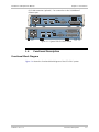
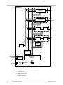
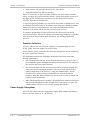
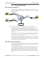
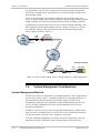
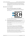
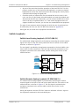
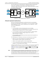
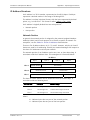
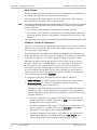
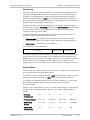
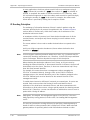
Chapter 1 Introduction
Installation and Operation Manual
System Timing
Internally, the FCD-E1LC uses one timing source (clock). This system clock
determines the transmit timing of the E1 main and sublinks and user channels,
and the timing of most other signal processing operations.
To achieve maximum flexibility in system integration and enable hierarchical
distribution of timing in the system, the FCD-E1LC enables you to select the
source to which the master clock is locked. The available options are as follows:
Note
•
Reference source locked to the recovered receive clock of the main link.
•
Reference source locked to the recovered receive clock of the sublink.
•
Reference source locked to an external clock (such as the transmit clock
applied to a data channel using the DTE2 mode).
The DTE2 mode is not available when the data channel uses the X.21 interface.
The Ethernet interface cannot be used as a reference source.
•
System clock source locked to the internal crystal oscillator, which has an
accuracy of ±50 ppm.
In addition to the selection of a master clock source, you can specify a fallback
source, which is automatically selected in case the master source fails. The fail
criteria are loss of the receive signal on the port selected as the master source,
or inactive RTS line on the data channels. The internal oscillator always serves as
a fallback source, which is automatically selected in case the other selected
timing sources fail.
Main Link Timing
FCD-E1LC recovers the main link receive clock signal, and uses it as the timing
source for the receive path. The main link transmit timing source, which is derived
from the main system clock, can be locked to one of the following sources:
•
Recovered receive clock
•
External clock signal derived from one of the synchronous data channels)
•
Sublink recovered receive clock
•
Internal oscillator.
Sublink Timing
FCD-E1LC recovers the sublink receive clock signal, and uses it as the timing
source for the receive path. The sublink transmit timing source is always derived
from the main system clock.
Synchronous Data Channel Timing
The FCD-E1LC data channel has three timing modes:
•
1-14
DCE – transmit and receive clock for the user’s equipment connected to the
data channel are derived from the main system clock.
Functional Description
FCD-E1LC Ver. 1.0