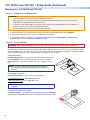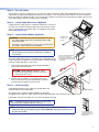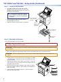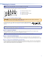
1
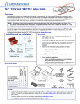
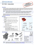
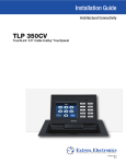
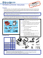
a V to 350C CV user P L the T TLP 350 ting nnec er to the ilable at o c a re ef Befo ource, r ich is av om. er s ide, wh xtron.c pow u e . g www TLP 350CV and TLE 350 • Setup Guide Overview The Extron TLP 350CV 3.5-inch Cable Cubby® TouchLink™ touchpanel and TLE 350 enclosure provide AV connectivity using convenient pullout cables. The TLP 350CV also provides simple and versatile configuration and control for a range of IP Link® control systems via an Ethernet connection, using a required IP Link controller, a touch screen, and 10 customizable buttons. Video and audio input is provided by two BNC connectors. NOTE: The network output must connect via a network switch, hub, or router to an Ethernet LAN or the Internet, with an Extron IP Link controller on the same network. Suggested controllers include IPL T S series (for example, IPL T S4), IPL 250, IPL T CR48, IPL T SFI244, or IPCP series. The first four pages of this guide provides basic instructions for experienced installers to mount either the TLP 350CV or the TLE 350. The last four pages show initial configuration for the TLP 350CV. For reference material and full instructions about configuring the touchpanel, see the TLP 350CV User Guide, which is available on the Extron website (www.extron.com). Tools Required for Installation Vacuum Cleaner Before making any cuts, select the best location for the TLP 350CV or TLE 350. Ensure that the edge that opens on the lid is oriented correctly. Ensure there is enough space for all the system cables and components, including cable retractors, if they are to be installed. Decide on the method for cutting a hole in the table: Square Tape Measure Safety Glasses Phillips Screw Driver 1/4" Hex Nut Driver Hand router and template zz CNC wood router zz Jigsaw and paper template Verify that you have the correct template or dimensions. Check all relevant regulations. zz Ensure the installation complies with local, state, and national building and electrical codes. zz Ensure the installation complies with the Americans with Disabilities Act or other accessibility requirements. Without Power Module With Power Module Included Parts zz AC Power Module* 1 0 Pass-through AAPs† 4 4 Blank AAPs 3 5 1-space bracket kit 0 0 2-space bracket kit 2 3 3-space bracket kit 1 1 Blank AAPs AC Power Module* Pass-thru AAPs #4−40 Screws and Nuts TLP 350CV or TLE 350 Zip Ties AAP Shelf Bracket Kits (2 brackets/kit) 12 VDC, 1 A Power Supply 100-240V 50-60Hz 1A MAX Marking Pen Planning Table Clamps 1 Pos 2 Pos 3 Pos NOTES: * † Inside the US, the TLP 350CV may be purchased with or without an AC power module. If a power module is required for the TLE 350, it must be purchased separately. Outside the US, see the Extron website to purchase an AC power module that is suitable for your location. Active or Passive AAPs must be purchased separately (see the Extron website). 1 TLP 350CV and TLE 350 • Setup Guide (Continued) Mounting the TLP 350CV and TLE 350 Step 1 — Obtain Cut-out Dimensions ATTENTION: • The table should be cut only by licensed and bonded craftspeople. • Make certain the correct cut-out dimensions are being used before proceeding to the next step. Extron is not responsible for mounting holes that are incorrectly cut. • The surfaces of the Cable Cubby enclosure have screws and other protruding hardware that could damage fine furniture. Do not rest the enclosure on unprotected furniture. • Ensure the table surface is at least 0.375 inches (0.95 cm) thick. zz If using a hand router, you should purchase the Extron TLP 350CV routing template (part number 70-694-01). zz If using a CNC wood router, use the exact cut-out dimensions (see below). zz If using a reciprocating saw or jigsaw use the paper cut-out template (part number 68‑2148‑01, available under the Downloads tab on the TLP 350CV page at www.extron.com.) Step 2 — Cut the Surface CAUTION: Risk of personal injury: To avoid eye injury, wear safety glasses when operating power equipment. Be certain the cut is laid out in exactly the desired location and the edge that opens on the lid is correctly oriented. After verifying and checking dimensions, cut a hole in the surface of the furniture where the enclosure will be installed (see “Preparing the Table” in the TLP 350CV User Guide). There are three methods for cutting the hole in the table: Using a hand router Recommended method — Use the Extron TLP 350CV routing template, part number 70-694-01. Refer to the Routing Template User Guide, available at www.extron.com, to prepare the template and use the template to cut the hole. NOTE: The metal router guide must be purchased separately. It CAB LE HSA CU 20 BB 0 Y 30 0 is reusable and should not be discarded when the installation is complete. USE H R SA AC 20 CES0 S Using a CNC wood cutter Recommended method — Use the exact cut-out dimensions: 7.50 +0.00/-0.02 inches W x 6.00 +0.00/-0.02 inches D (19.05 +0.00/-0.05 cm W x 15.24 +0.00/-0.05 cm D) NOTE: The underlined dimension is the connector or AAP access side for the unit. Using a reciprocating saw or jigsaw C u T n tro Ex e r th fo V te C pla 0 em 71 tu T P t-O L " 17 x 1" :1 : 1 1 k. ze ale in si c r e t s t sh g in Pa Pr no o D O d. lle sta a in are be ut to t-o or ct cu . all V du ce late w 0M e 1 ro a p p th e urf m n 7 th e s e te o TLP th th n e firm e m itio th . on ov o os C m ) fr p here ed e ll e 1. R ray th w sta g. 2. (g ark ure in enin M rnit ing op 3. fu be e is t th u C 4. g in R m e.) Tri lin of is e th dg cut r E ot ute o n (D P/N/ 68 -2 04 6-0 1 R .B ev Acceptable method — Use the paper cut-out template (part number 68‑2148‑01, available under the Downloads tab on the TLP 350CV page at www.extron.com.) 2 C USEAB LE R AC CUBB CES Y S 300 Step 3 — Run all Cables Run all cables necessary to support the AC connector, the cables stored in the cubby, and all planned AAP connectors. Run the cables below the table and through the hole that was cut in Step 2. Leave enough slack in the cables to connect or route them before the cubby is installed in the table. Leave enough space under the enclosure for the external power supply and connection of AV cables and the network connection for the TLP 350CV. Step 4 — Install Cable Retractors (Optional) If required, Extron cable retractors should be installed in the enclosure at this stage. For complete information about retractors and how to install them, see the Retractors User Guide, which is available from the Extron website (www.extron.com). Step 5 — Install Power Module (Optional) ATTENTION: For units that are used in North America, only use AC power modules that are UL Listed Model “Cable Cubby AC Power Module”. Install the power module on the left side. The unit is not UL Listed if it uses any AC power module other than Model “Cable Cubby AC Power Module”. NOTE: For models that do not include a power module, see the Extron website to select a power module that is suitable for your location. The power module takes up two or three AAP spaces, depending on the model, and may be installed before or after the AAP assembly is installed. It may be installed with AAPs on either side. Push the module through the bottom of the enclosure. Secure the module in place with #4-40 Phillips head screws and star washers. 1. Secure the power module into position with #4-40 Phillips head screws and star washers. CAUTION: Risk of electric shock: To ensure good electrical grounding, you must use the star washers with the screws. 2. Run the cable or conduit to a convenient junction box. Extron recommends the circuit be attached to a junction box that is directly wired to the main circuit. Step 6 — AAP Assembly Install all desired cables into the cable pass‑through AAPs and install the AAPs into the Cable Cubby. Rear Brackets The simplest way to install the cables and AAPs is to populate Front Brackets the AAP brackets outside the cubby and then install the populated AAP shelf assembly into the cubby. Install cables in the pass-through holes as shown in the figure to the right. TIP: Hand tightening the #4-40 nuts makes it easier to place and secure the assembly inside the enclosure. NOTE: An extra column of AAP bracket mounting points is available for use with TLP single‑space AAP mounting brackets (part number 70-693-01). Single-space brackets do not fit in any other location. The extra column of mounting points is for installing single-space AAP brackets. 3 TLP 350CV and TLE 350 • Setup Guide (Continued) Step 7 — Install the AAP Assembly 1. From under the table, push the first AAP assembly through the bottom of the enclosure. The holes in the rear bracket must align with the bottom row of holes on the rear face of the enclosure. TIP: Ensure there is enough space above the AAP assembly for the lid to close completely without cables or connectors contacting the touchpanel. 2. Secure the AAP assembly into position with the provided Phillips head screws. Philips Head Screws (secures AAP Shelf Assembly) 3. Tighten the nuts that secure the AAPs to the brackets. 2 Large holes provide tool access to fasten rear brackets. A U D IO 1 Push assembly through bottom of enclosure. R TE PU M CO 3 Tighten down AAP Nuts. Step 8 — Mounting the Enclosure Mount the Cable Cubby enclosure in the table. CAUTION: Risk of personal injury: The flanged edges of the trim ring are sharp. Exercise caution when the cubby is not installed in a table to prevent personal injury. ATTENTION: The trim ring edges are soft and can easily be nicked or bent. Exercise caution when handling and mounting the enclosure. 1. Remove the edge grommet protecting the edges of the trim ring and the plastic film on the finished surfaces. ATTENTION: Do not use isopropyl alcohol or other solvents to clean the Cable Cubby. Strong solvents will ruin some finishes. 2. Carefully lower the enclosure into the hole cut in the table (see “Step 2 — Cut the Surface” on page 2). Ensure the trim ring (e) is flush with the top of the table. c) to the pins on each side of the enclosure. It may be necessary to loosen the wingnuts (a) and the Phillips head screws (b). 3. Under the table, attach the table clamps ( 4. When the clamps are properly seated on the pins, tighten the Phillips head screws until the clamp faces (d) are tightly secured against the bottom of the table. 5 4 5. To prevent the screws from becoming loose, secure the wingnuts against the table clamp bodies. 1 3 2 4 Connecting the TLP 350CV NOTE: The rest of this guide applies only to the TLP 350CV (not to the TLE 350). The cable connections are located in a panel on the bottom of the TLP 350CV: a b c d VID / Y POWER 12V 1.0A MAX LAN C PREVIEW INPUT a b c d External power supply connector LAN and PoE connector Composite or S-video luma signal S-video chroma signal Step 9 — Connect the External Power Supply ATTENTION: Before connecting the power supply, read the cautions listed in the “Power Connector” section of the TLP 350CV User Guide, which is available at www.extron.com. POWER 12V 1.0A MAX - Connect the two pole, 3.5 mm captive screw connector from the power supply (provided with the unit) to the power supply socket on the rear panel (a). The power supply provides 12 VDC and 1.0 A. 3/16" (5 mm) Max. NOTE: For advice about using captive screw connections, see the notes in the “Power Connector” section of the TLP 350CV User Guide, which is available at www.extron.com. Step 10 — Connect the Network Using a standard Ethernet cable, connect the TLP 350CV to the network via the LAN port (b). The TLP 350CV must be connected to the same network environment as the assigned IP Link controller. NOTE: To configure the TLP 350CV, connect it directly to a PC with an Ethernet crossover cable. Step 11 — Connect the Preview Inputs Two BNC connectors carry video from a composite or S-video source allowing a TLP 350CV user to preview video from that source. Composite video is connected to Vid/Y (c). For S-video, the luma signal is connected to Vid/Y (c) and chroma to C (d). Step 12 — Power on the TLP 350CV for the First Time Power on all the devices connected to the TLP 350CV. When the 12 VDC power supply is switched on, the TLP 350CV will boot up and, if a graphical user interface (GUI) has been designed and loaded onto the touchpanel, that screen will be displayed. If a GUI has not been loaded, a plain blue screen will be displayed. 5 TLP 350CV and TLE 350 • Setup Guide (Continued) Front Panel Features With the lid down, the screen, light sensor, and the illumination LED are disabled. They are all activated by opening the lid. 4 1 5 6 7 2 8 3 For a complete description of all these features and their function, see the TLP 350CV User Guide. a Light Sensor — monitors ambient light level and adjusts screen brightness. b LCD screen — has a 320x240 resolution with a touch overlay. Extron software is used to design and configure a graphic user interface to display buttons, text, or icons, which have user‑defined functions associated with them (see GUI Design and Configuration on page 8). c d Speaker — provides audible feedback for the user. e f g h Menu Button (under faceplate) — activates the on-screen menus for calibrating the unit. Configurable Side buttons — 10 dedicated, customizable function buttons provide quick access to key functions. A set of replacement buttons is included with the TLP 350CV. Individual buttons with additional labels are available on the Extron Web site. See the TLP 350CV User Guide for instructions on changing the buttons. Reset Button (under faceplate) — allows the unit to be reset to one of four different modes (see page 8). Reset LED — provides feedback about the mode status when the user presses the reset button. Illumination LED — provides light for cable cubby enclosure. NOTE: The menu and reset buttons are accessible through small holes without removing the faceplate. A paperclip may be used to press the buttons. 6 Initial Configuration Before use, configure the touchpanel, using the on-screen menus. e in the figure on page 6). The Main menu screen opens. 1. Press the Menu button once ( Main Sleep timer: 005 Min Down Vol Vid Up Backlight: 073% Down Up Time IP Auto Backlight LED Backlight On On Exit 2. Touch an on-screen button to highlight and select that option (the button turns green with a yellow border). 3. Use the Up and Down buttons to adjust the value. Some options have a single button and toggle between Off and On when the button is pressed. There are five different screens (Main, Volume, Time, Network, and Video) that can be selected by pressing the appropriate button at the left side of the screen. There is also an Exit button at the bottom right corner of the screen for saving changes and leaving the menus. Use the screens to adjust the following options (for more information, see the TLP 350CV User Guide). Main — Adjusts the Sleep timer, Backlight, Auto Backlight, and LED Backlight functions. Volume — Adjusts the Master, Click, Sounds, and Line In volume settings. Time — Sets the correct time and date. IP — (Network configuration) Sets the IP Address and the Subnet Mask, and enables or disables Dynamic Host Configuration Protocol. Video — Provides a small video preview window and the controls to adjust the video contrast, color, brightness, and tint. 7 TLP 350CV and TLE 350 • Setup Guide (Continued) Calibration Screen e) once to access the calibration menu. From any other screen, press the recessed menu button twice (within one second) to access the calibration menu. The calibration screen opens with the on-screen button in the top left corner highlighted. 1. From the main setup screen, press the recessed menu button ( + + Press and Hold Highlighted Box Until Color Changes + + 2. Press the highlighted button until it turns gray and a new button is highlighted. When all four points have been calibrated, the screen reopens to the Main Screen. 3. Press Exit to close the on-screen menus. 4. Reattach the bezel. Reset Modes The touchpanel has four reset modes: Factory Firmware Mode, Run or Stop Events Mode, Reset All IP Settings Mode, and Reset Factory Defaults Mode. These modes can be initiated by pressing the reset button (f in the figure on page 6). Do not use the reset button until you have read all the information about the different modes (see the TLP 350CV User Guide). GUI Design and Configuration Use Extron GUI Configurator (version 1.3 or later) to design the graphical user interface that will appear on the TouchLink panel. Use Extron Global Configurator (version 3.3 or later) to assign functions to the elements of the graphical user interface. For complete information about these software programs, see the help file of the appropriate program. Extron Headquarters +1.800.633.9876 (Inside USA/Canada Only) Extron USA - West Extron USA - East +1.714.491.1500+1.919.850.1000 +1.714.491.1517 FAX +1.919.850.1001 FAX Extron Europe +800.3987.6673 (Inside Europe Only) +31.33.453.4040 +31.33.453.4050 FAX Extron Asia +65.6383.4400 +65.6383.4664 FAX Extron Japan +81.3.3511.7655 +81.3.3511.7656 FAX Extron China +86.21.3760.1568 +86.21.3760.1566 FAX Extron Middle East +971.4.299.1800 +971.4.299.1880 FAX © 2013 Extron Electronics All rights reserved. www.extron.com 8 Extron Korea +82.2.3444.1571 +82.2.3444.1575 FAX Extron India 1800.3070.3777 (Inside India Only) +91.80.3055.3777 +91.80.3055.3737 FAX 68-1692-50 Rev. C 04 13