1
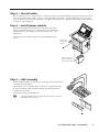
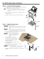
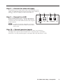
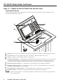
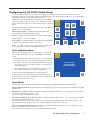
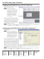
TLP 350CV Setup Guide The Extron TouchLink™ 3.5 inch Cable Cubby® TLP 350CV provide users with access to AV connectivity using convenient pullout cables. It also provides simple and versatile configuration and control for a range of IP Link® control systems. With a required IP Link controller, the touchpanel and 10 customizable buttons provide control of an AV system and room environment. On-screen graphic and text objects allow users to activate or regulate system control functions. The TLP 350CV communicates with the configurable IP Link controller via an Ethernet connection. Two BNC connectors allow the screen to be used to preview composite video or S-video. N The RJ-45 output on the rear panel of the TLP 350CV must be connected to a network switch, hub, or router that is connected to an Ethernet LAN or the Internet. An Extron IP Link controller must also be connected to the same network. Suggested models include: • IPL T S series • IPL T CR 48 • IPL 250 • IPL T SFI 244 This guide provides basic instructions for an experienced installer to mount and perform initial configuration on the TLP 350CV. When possible in the following pages, line drawings are used to clarify steps discussed in the text. Where appropriate, images have one or more numbers corresponding to a specific step described. Visit the TouchLink™ panel site at www.extron.com/touchlink for assistance in the setup and operation of the TLP 350CV, or to enroll in online training. For additional assistance with the touchlink panels, call 1.800.633.9877. Installation Overview Install and set up the TLP 350CV enclosure as follows: c Verify the surface cutout dimensions of the TLP 350CV "Step 1 — Obtain cutout dimensions" on page 2. To obtain the most recent cutout dimensions, visit the Extron Web site at www.extron.com. c If planning to use a routing template that has not been prepared, prepare the template. Refer to the TLP 350CV User’s Manual, available on the included DVD or the Extron Web site, www.extron.com. c Cut a hole in the surface where the enclosure will be installed. See "Step 2 — Cut the surface" on page 2. Use one of the following as a guide: • The optional metal routing template • The cut-out dimensions, programmed into a CNC wood router • A paper surface cut-out template Run all cables necessary to support the AC connector, the cables stored in the cubby, and all planned AAP connectors. See "Step 3 — Run all cables" on page 3. Leave enough slack in the cables to connect or route them before the cubby is installed in the table. c c Install the power module. If the location requires electrical conduit, install an Extron flexible conduit kit. Refer to the Flexible Conduit Kit Installation Instructions, Extron part #68-734-01 available at www.extron.com. See "Step 4 — Install power module" on page 3. c Install cables into the cable pass-through AAPs and loosely fasten to the AAP Shelf. If applicable, install passive AAPs and loosely fasten to the AAP shelf. Connect cables to the rear connectors. See "Step 5 — AAP assembly" on page 3. c Install the AAP shelf assembly into the Cable Cubby. See "Step 6 — Install the AAP assembly" on page 4. c Mount the TLP 350CV in the table. See "Step 7 — Mount the enclosure" on page 4 c Connect the external power supply. See "Step 8 — Connect the external supply" on page 5. c Connect a LAN cable. See "Step 9 — Connect to a LAN" on page 5. c If using the video monitoring capabilities of the TLP 350CV, make video input connections. See "Step 10 — Connect preview inputs" on page 5. c Apply power. See "Step 11 — Power on the TLP 350CV for the first time" on page 6". 68-1692-50 Rev. A 12 09 TLP 350CV Setup Guide, Continued Step 1 — Obtain cutout dimensions Determine the optimum location for the TLP 350CV keeping in mind the size of the enclosure that will be below the table and also the ease of operation for a user. Cutout dimensions are available as a router guide, printed dimensions and a cutout template. If using the router guide, follow the instructions included with it. Printed dimensions are available in the Appendix of the TLP 350CV User's Manual available on the included DVD or at www.extron.com. W Make certain the correct cutout dimensions are being used before proceeding to the next step. Extron is not responsible for improperly positioned Cable Cubby models. W Wear safety glasses when operating power equipment. Failure to comply can result in eye injury. Double-check before you cut: c If using a routing template, be certain the correct template for the TLP 350CV is being used. c If using a CNC router, be certain the correct dimensions for the TLP 350CV are entered. c If using a reciprocating saw or jigsaw, be certain the correct paper template for the TLP 350CV is being used. c Be certain the cut is laid out in exactly the desired location. c Be certain the cut is laid out so the connector access side is oriented as desired. Step 2 — Cut the surface After verifying and checking dimensions, cut a hole in the surface of the furniture where the enclosure will be installed. See "Preparing the Table" in chapter 2 of the TLP 350CV User’s Manual. C The opening in the table for the Cable Cubby should be cut only by licensed and bonded craftspeople. Exercise care to prevent scarring or damaging the furniture. The surfaces of the Cable Cubby enclosure have screws and other protruding hardware that could damage fine furniture. Do not rest the enclosure on unprotected furniture. C Ensure the table surface is at least 3/8 inch (0.375 in) (0.95 cm) thick. There are three methods for cutting the hole in the table: • Hand router, • CNC wood cutter, and • reciprocating saw or jigsaw A hand router using the routing template or a CNC wood router are the most accurate, preferred, and recommended methods for preparing the table for the TLP 350CV. RECOMMENDED — A hand router and the Extron TLP 350CV routing template, part #70-694-01. Refer to the Routing Template User’s Manual, available on the Extron Web site, www.extron.com, to prepare the template and use the template to cut the hole. N The metal router guide is reusable. Do not discard this router guide when the installation is complete. RECOMMENDED — A CNC wood router and the exact cut-out dimensions: 7.50 +0.00/-0.02 in W x 6.00 +0.00/-0.02 in D (19.05 +0.00/-0.05 cm W x 15.24 +0.00/-0.05 cm D) N 2 The underlined dimension is the unit’s connector or AAP access side. Acceptable — A reciprocating saw or jigsaw and a paper cut-out template (available on the Extron Web site, www.extron.com.) TLP 350CV Cable Cubby • Setup Guide Step 3 — Run all cables Run all cables necessary to support the AC connector, the cables stored in the cubby, and all planned AAP connectors. Leave enough slack in the cables to connect or route them before the cubby is installed in the table. Leave enough space under the enclosure for the external power supply and connection of computer and AV cables and the network connection of the TLP 350CV. Step 4 — Install power module Install the included power module before installing other AAPs. The power module takes up two or three AAP spaces and must be installed in the location furthest to the left of the enclosure. (See illustration.) Secure the power module into position with #4-40 Phillips head screws. Install the power module on the left side. Push module through bottom of enclosure. Secure in place with screws. Step 5 — AAP assembly Install all desired cables into the cable pass‑through AAPs and install the AAPs into the Cable Cubby. A U D IO The simplest way to install the cables and AAPs is to populate the AAP brackets outside the cubby and then install the populated AAP shelf assembly into the cubby. R TE PU M CO Install cables in the pass-through holes: T Leaving the #4-40 nuts finger tight will make it easier to place the assembly into the enclosure. TLP 350CV Cable Cubby • Setup Guide 3 TLP 350CV Setup Guide, Continued Step 6 — Install the AAP assembly 1. From the underside of the Cable Cubby, gently push the AAP shelf assembly into position at the desired elevation. T Ensure there is enough space above the AAP assembly for the lid to close completely without cables or connectors contacting the touchpanel. 2. Secure the AAP shelf assembly into position with the provided Phillips head screws. 3. Tighten the nuts that secure the AAPs to the shelf brackets. 2 Philips Head Screws (secures AAP Shelf Assembly) A U D IO 1 Push assembly through bottom of enclosure. R TE PU M CO Step 7 — Mount the enclosure Mount the Cable Cubby in the table. W The flanged edges of the trim ring are sharp. Exercise caution when the cubby is not installed in a table to prevent personal injury. C The trim ring edges are soft and can easily be nicked or bent. Exercise caution when handling and mounting the enclosure. 1. AAP Nuts Remove the edge grommet protecting the corners of the trim ring and the plastic film on the finished surfaces. C Do not use isopropyl alcohol or other solvents to clean the Cable Cubby. Strong solvents will ruin some finishes. 2. Carefully lower the Cable Cubby enclosure into the cut out to test the fit. If necessary, remove the enclosure and use a file or rasp to enlarge or smooth edges of the opening. 3. Install the table clamps onto the pins on the side of the enclosure. 4. Snugly tighten the screws on the clamps to secure the enclosure to the bottom of the table. C 5. 3 Tighten down DIS PLA Y ON DIS PLA Y OF F AU TO Ex tron VO LU ME PC LAP TO P IMA GE VO LU ME DV D DO C CA M AU XIL IAR Y Do not overtighten the screw clamps. Overtightening can bend the horizontal flange of the table clamp. Table Clamp Tighten the wing nuts on the table clamps to lock the clamp in position. Both Sides 4 TLP 350CV Cable Cubby • Setup Guide Step 8 — Connect the external supply Connect the two pole, 3.5 mm captive screw connector from the power supply (provided with the unit) to the power supply socket on the rear panel (a). The power supply provides 12 VDC and 1.0 A. a b c d Step 9 — Connect to a LAN Using a standard ethernet cable, connect the TLP 350CV to the network via the LAN port (b). The TLP 350CV must be connected to the same network environment as the assigned IP Link controller. POWER 12V 1.0A MAX LAN VID / Y C PREVIEW INPUT N For graphic user interface configuration, a PC may be directly connected to the TLP 350CV with an ethernet crossover cable. Step 10 — Connect preview inputs Two BNC connectors carry video from a composite or S-video source allowing a TLP 350CV user to preview video from that source. Composite video is connected to Vid/Y (c). For S-video, the luma signal is connected to Vid/Y (c) and chroma to C (d). TLP 350CV Cable Cubby • Setup Guide 5 TLP 350CV Setup Guide, Continued Step 11 — Power on the TLP 350CV for the first time Front Panel Features The front panel provides control and operation of connected devices via the touchscreen, the side buttons, and a speaker mounted inside the cable well. a d b e f g h c a b c d Light Sensor — Provides auto-dimming of the display to maximize viewability in differing lighting conditions. LCD touchscreen — The backlit LCD screen has a resolution of 320 x 240, with touch overlay. Speaker — Supports aural feedback of button or panel presses. Configurable Side buttons — 10 dedicated, customizable function buttons provide quick access to key functions. A set of replacement buttons is included with the TLP 350CV. Individual buttons with additional labels are available on the Extron Web site. See the TLP 350CV User's Manual for instructions on changing the buttons. e f Menu Button (under faceplate) — A menu button is used to adjust system and display preferences. g h Reset LED Indicator (under faceplate) — Green LED that flashes to indicate the various reset modes. Reset Button (under faceplate) — A reset button is used to activate any of the predefined factor reset modes, including returning the panel to factory defaults. Illumination LEDs — A small block of LEDs illuminate the Cable Cubby inner AAP plates. N The menu and reset buttons are accessible through small holes without removing the faceplate. A paperclip may be used to press the buttons. 6 TLP 350CV Cable Cubby • Setup Guide Configuring the TLP 350CV (Initial Setup) Prior to using the TLP 350CV, it is essential to configure it, using the on-screen menus. The setup menu and calibration screen are accessed using the front panel menu button (e). Press the menu button once to enter the Main setup menu and twice to access the calibration screen. There are five screens selected by pressing the appropriate button at the left and upper right side of the screen. There is also an Exit Sleep timer: 50000 Sec Main Vid button at the bottom right corner of the screen for leaving the setup Down Up menus. The setup menu pages adjust the following features. For additional details, see the User's Manual. Main ( shown at right) — Adjusts the Sleep timer, Backlight, Auto Backlight, and LED Backlight functions. Vol Backlight: 073% Down Volume — Adjusts the Master, Click, and Sounds volume settings. Time Time — Sets the correct time and date. Network (IP) — Sets the IP address, the subnet mask, and enables or disables Dynamic Host Configuration Protocol. Up IP Auto Backlight LED Backlight On On Exit Video — provides a small video preview window and the controls to set up the video contrast, color, brightness, and tint. Enter Calibration Menu If the touchscreen panel does not react properly to a finger touch, it may require calibration. To access the touchpanel calibration screen: + 1. From the main setup screen (shown above), press the recessed menu button (e) once to access the calibration menu. From any other screen, press the recessed menu button twice (within one second) to access the calibration menu. The screen shown on the right appears. + Press and Hold Highlighted Box Until Color Changes 2. Press and hold on the green box until the color reverts to grey with a white border and a second box is highlighted. 3. Move to the newly highlighted box and repeat step 2. 4. Repeat until all four boxes have been pressed and are gray. + + Once all four boxes have been calibrated the screen automatically returns to the Main menu (see above). Reset Modes The TLP 350CV has four reset modes that can be initiated by pressing the Reset button (Front Panel (f)): Factory Firmware Mode: Hold the Reset button while applying power to reset the unit back to the firmware shipped with the unit. Run/Stop Events Mode: Hold the Reset button until the reset LED (g) blinks once (~3 sec.), then release and within 1 second, press Reset momentarily (<1 sec.). This mode toggles events either On or Off. Reset All IP Settings Mode: Hold the Reset button until the reset LED blinks twice (~6 sec.), then release and within 1 second, press Reset momentarily (<1 sec). This mode resets the IP address, subnet, gateway, port mapping, and DHCP settings back to factory defaults. The reset LED blinks 4 times in quick succession, confirming the reset and turning events off. Reset Factory Defaults Mode: Hold the Reset button until the reset LED blinks 3 times (~9 sec.), then release and within 1 second press Reset momentarily (<1 sec). This mode causes a complete reset to factory defaults (except firmware). TLP 350CV Cable Cubby • Setup Guide 7 TLP 350CV Setup Guide, Continued Designing the TLP 350CV Interface with GUI Configurator Install the GUI Configurator software on a PC and use it to design the interface that will appear on the TLP 350CV screen. N The Extron GUI Configurator software is on the disk included with the TouchLink Panel and may also be downloaded (free of charge) from the Extron Web site (www.extron.com). For information about downloading GUI Configurator, consult the TLP 350CV User's Manual, also available from the Extron Web site (www.extron.com). Open the program by clicking on the desktop icon or by using Windows Explorer to navigate to the correct file on your computer. When the program opens (see the screen at right), there is an option to open an existing project, open an existing template, or start a new project to design a completely new interface. N Consult the GUI Configurator Help File for information about using GUI Configurator. To open the help file, click on the Help menu and select Contents or press the F1 button on your keyboard. Configuring the TLP 350CV Interface with Global Configurator 3 Install the Global Configurator 3 software on a PC and use it to assign functions to the screen elements created with GUI Configurator. N The Extron Global Configurator 3 software is on the disk included with the TouchLink Panel and may also be downloaded (free of charge) from the Extron Web site (www.extron.com). For information about downloading Global Configurator 3, consult the TLP 350CV User's Manual. Open the program by clicking on the desktop icon or by using Windows Explorer to navigate to the correct file on your computer. When the program opens (see the screen at right), follow the on‑screen instructions to configure the IP address of the units. Open the project created with GUI Configurator 3 and assign functions to the buttons and screen graphics and text. When the functions have been assigned to all screen objects, build the project and upload it to the IP Link unit. For complete information, consult the TLP 350CV User's Manual N Consult the Global Configurator 3 Help File for information about using Global Configurator 3. To open the help file, click on the Help menu and select Contents or press the F1 button on the keyboard. Extron USA - West Headquarters +800.633.9876 Inside USA / Canada Only +1.714.491.1500 +1.714.491.1517 FAX Extron USA - East Extron Europe Extron Asia Extron Japan Extron China Extron Middle East +800.633.9876 +800.3987.6673 +800.7339.8766 +81.3.3511.7655 +81.3.3511.7656 FAX +400.883.1568 +971.4.2991800 +971.4.2991880 FAX +1.919.863.1794 +1.919.863.1797 FAX +31.33.453.4040 +31.33.453.4050 FAX +65.6383.4400 +65.6383.4664 FAX Inside USA / Canada Only Inside Europe Only Inside Asia Only © 2009 Extron Electronics. All rights reserved. Inside China Only +86.21.3760.1568 +86.21.3760.1566 FAX