1
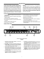
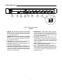
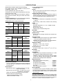
0RGHO6&06&0(
8VHU*XLGH
6&06&0(
(,*+7&+$11(/0,&523+21(0,;(5
¢6KXUH,QFRUSRUDWHG
&5HY 3ULQWHGLQ86$
DESCRIPTION
switchable 48 V phantom power, and a 1/4-inch send/receive
insert jack.
The SCM800 operates on 120 Vac power; the SCM800E operates 230 Vac power. Both models are supplied with rackmounting hardware, link cable and removable block terminal
connectors. An accessory rack panel adapter (Model
RKC800, available separately) converts the removable block
input and output connectors to XLR connectors, and the Aux
connectors to phono jacks.
The Shure Model SCM800 is a full-featured, eight-channel microphone mixer for sound reinforcement, general audio recording, and audio-visual systems. Any low-impedance, balanced dynamic or condenser microphone, including a wireless microphone system, can be used with the SCM800 mixer.
Each SCM800 accepts up to eight microphone- or line–level
inputs and one aux-level input (two input jacks feed the same
channel). Up to four SCM800 mixers can be linked to provide
up to 32 input channels. Each input channel has a two-band
equalizer, switchable microphone- or line-level operation,
FEATURES
S Compatible with Shure SCM810 and FP410 automatic miS
S
S
S
S
S
crophone mixers
Adjustable EQ per channel: low-frequency rolloff and highfrequency shelving
48 V phantom power selectable for each input
S
S Active balanced microphone- and line-level inputs and linelevel output
Linking capability for systems up to 32 microphones
Two Aux-level input jacks that feed one channel
Insert jack on each channel
Manual mixing of input channels
Internal Modification permits 230 V operation (SCM800) or
120 V operation (SCM800E)
Front-panel headphones output with level control
S
S Peak-responding output limiter with selectable thresholds
S Highly RF-resistant chassis and circuitry
S LED indication of channel clipping
and LED indicator
SCM800 FRONT PANEL
1
3
2
5
4
7
6
8
10
9
MODEL SCM800/E FRONT PANEL
FIGURE 1
6. AUX INPUT 1/4-inch Phone Jack: Mixes external auxiliary- or line-level sources, i.e., tape recorders, into output.
Signal appears at output of all linked mixers.
7. MASTER Level Control: Determines the overall mix level.
8. Output Level Meter: Nine-segment LED meter indicates
peak output signal level. Last LED indicates limiter action.
9. PHONES Control and 1/4-inch Phone Jack: Permits
monitoring of mixer output through headphones.
PHONES control determines headphones output level.
10. POWER LED: Lights green when unit is powered.
1. Microphone Channel Gain Controls 1 - 8: Allows adjustment of microphone gain.
2. Input LED 1 - 8: Lights red at 6 dB below clipping level.
3. Low-Cut Filter 1 - 8: Recessed screwdriver adjustment
provides adjustable low-frequency rolloff (high pass) to
reduce undesirable low-frequency signals.
4. High-Frequency Shelving Filter 1 - 8: Recessed screwdriver adjustment provides level boost or cut in mid/highfrequency region for compensation of off-axis lavalier microphones, or for cutting the high-frequency sibilance of
vocal microphones.
5. AUX Level Control: Sets the input level for aux-level
equipment connected to the adjacent 1/4-inch phone jack
INPUT or rear-panel 1/4-inch AUX input.
3
SCM800 REAR PANEL
120VAC 50/60 Hz 200mA
LINK
OUT
AUX/INS/INS INSERT
INSERT
INSERT
INSERT
INSERT
INSERT
INSERT
INSERT
(SWITCH) AUX IN
MIC/PHM/LINE
MIC/PHM/LINE
MIC/PHM/LINE
MIC/PHM/LINE
MIC/PHM/LINE
MIC/PHM/LINE
MIC/PHM/LINE
MIC/PHM/LINE
LINE
SWITCH
SWITCH
SWITCH
SWITCH
SWITCH
SWITCH
SWITCH
SWITCH
OUTPUT
LINK
IN
+Ć
11
12
13
8
14
+Ć
7
6
+Ć
16
17
+Ć
5
+Ć
15
4
3
+Ć
18
+Ć
2
+Ć
MICĆ
LEVEL
(MIC)
1
+Ć
PHANTOM
LINEĆ
(PHM)
LEVEL
(LINE)
(SWITCH BEHIND
CONNECTOR)
MODEL SCM800/E REAR PANEL
FIGURE 2
15. SEND/RECEIVE 1/4-inch Insert Jacks: Post-fader,
post-EQ insert point to add external compressor/limiter,
graphic or parametric EQ, or other signal processors. Tip
is send, ring is return. Can be modified for use as a Direct
Out (see Internal Modifications).
16. AUX/INS/INS 3-Position Slide Switch: Selects either
aux input function or insert function for channel 8 (only) Insert jack. Left switch position is AUX IN; center and right
positions are INSERT. This switch is located behind Line
Output connector.
17. INPUT 1-8 Removable Block Connectors: Active balanced microphone- or line-level inputs.
18. Input 1 - 8 MIC/PHM/LINE 3-Position Slide Switch: Selects operation at either microphone-level (left), microphone-level with 48 V phantom power (center), or line-level (right) signals. This switch is located behind the removable block connector.
11. SCM800: 120 VAC Power Connector and Rocker
Switch: Switch turns unit on when power cord is plugged
into 120 Vac. Can be internally changed to 230 V operation (see Voltage Selection).
SCM800E: 230 VAC Power Connector and Rocker
Switch: Switch turns unit on when power cord is plugged
into 230 Vac. Can be internally changed to 120 V operation (see Voltage Selection).
12. DIP Switch: The 7-position DIP switch provides control
of the output limiter threshold (see DIP Switches).
13. LINK IN/OUT Jacks: Permit multiple SCM800 mixers to
be stacked for additional inputs.
14. LINE OUTPUT Removable Block Connector: Active
balanced line-level signal for connection to amplifiers, recorders or other mixers. If necessary, output level can be
changed to microphone level. Refer to the Internal Modifications section of this manual.
4
SYSTEM SETUP
RACK MOUNTING THE SCM800/E
To mount an SCM800 or SCM800E in a standard 483 mm
(19-inch) audio equipment rack so that the front panel faces
out, as shown in Figure 4. Then secure secure the mixer to the
rack with the four supplied Phillips head screws.
RACK MOUNTING THE SCM800/E
FIGURE 4
SCM800/E CONNECTIONS
Refer to Figure 5 and proceed as follows:
1. Connect microphone- or line-level signal sources to the
Channel Input connectors (use conventional two-conductor shielded cables).
2. Insert a screwdriver or similar tool into the slot above each
block connector and adjust the input slide switch as required: microphone level (left position), 48 V phantom
power (center position), or line level (right switch position).
3. Connect the Line Level Output of the SCM800/E to the
input of other mixers, equalizers, amplifiers, or recorders.
If multiple SCM800/E mixers are to be used, refer to the
Mixer Linking paragraph of this manual.
4. If headphone monitors are to be used, plug them into
the1/4-inch PHONES jack on the front-panel.
5. Connect the power cord to a 120 Vac (SCM800) or 230
Vac (SCM800E) power source.
TO STEREO OR MONO HEADPHONES
FROM AUX– OR LINE–LEVEL SOURCE
TO AMP/REC/MIXER INPUT (CH. 1–7)
FROM MIC/LINE SOURCE (CH. 1–8)
TO AMP/RECORD/MIXER INPUT
OR FROM AUX SOURCE (CH. 8)
MIXER OUTPUT TO AMP/REC/MIXER INPUT
TO LINKED SCM800 MIXERS
TO POWER SOURCE
NOTE: For instructions on how to change the operating voltage of either model, refer to the Internal Modifications section
of this manual.
SCM800/E AUDIO CONNECTIONS
FIGURE 5
OUTPUT LIMITER THRESHOLD SETTINGS
The DIP switches on the rear-panel, shown below in Figure 3,
control the output limiter threshold settings. Switches 5 and 6
change the output limiter threshold to OFF (default setting),
+16 dBm, +8 dBm, or +4 dBm. Other settings are as shown in
the table at right. Refer to the Internal Modifications section of
this manual for additional settings.
NOTE: Switches 1, 2, 3, 4 and 7 are inactive and are not used.
DIP SWITCH FUNCTIONS
DIP Switch Position
Limiter Threshold
5 Up
Limiter Off
6 Up
(default)
5 Down
6 Up
5 Up
6 Down
(MIXER
REAR
PANEL)
5 Down
6 Down
1 2 3 4 5 6 7
OUTPUT LIMITER THRESHOLD DIP SWITCH
FIGURE 3
5
+8 dBm
+16 dBm
+4 dBm
LINKING MULTIPLE SCM800 MIXERS
Up to four SCM800 mixers can be “linked” using the supplied
link cables If additional inputs are needed. Such a configuration can provide 32 mic inputs. Refer to Figure 6.
When multiple SCM800 mixers are linked, all input signals appear at all linked mixer outputs––there is no master-slave relationship. The output controls and functions of each linked mixer are post-link and do not affect the signals appearing at other
linked mixer outputs. Each mixer’s Master level control only
controls its own output. Each output can be used independently. In a linked system, the Aux input of any mixer appears at
each linked mixer’s output. See Internal Modifications to defeat the linking of Aux signals.
Link jacks should be connected sequentially: the LINK OUT of
one mixer to the LINK IN of the next, leaving one LINK OUT
and one LINK IN unconnected.
NOTE: Each doubling of the number of linked mixers decreases the master output level by 6 dB.
LINKING MULTIPLE SCM800/E MIXERS
FIGURE 6
LINKING TO OTHER SHURE AUTOMATIC MIXERS
An SCM800 can be interfaced with Shure SCM810 and FP410
automatic microphone mixers via the link jacks. Linking an
SCM800 is equivalent to adding an additional mixer with eight
open microphones to a system. Because of the loading effects
of additional open microphones, only one SCM800 can be
linked to an automatic system. When using more than one
SCM800 with other Shure automatic mixers, connect them as
described in the following section.
NOTE: When linking an SCM800 to an automatic system, use
the SCM800 LINK OUT jack to interface with the LINK IN jack
of the automatic system (see Figure 7).
LINKING AN SCM800/E TO OTHER AUTOMATIC MIXERS
FIGURE 7
USING AN SCM800 AS A SUBMIXER
The master output of the SCM800 (or the output of a mixer in a
group of linked SCM800 mixers) can be connected to a channel input or the aux input of an automatic mixer, or other types
of mixers. See Figure 8.
SCM800
OUT
IN
SCM800
IN
LINE OUT
MIC IN
SCM810
USING AN SCM800/E AS A SUBMIXER
FIGURE 8
ADDITIONAL LINK CABLES
Additional 381 mm (15 in.) link cables are available as Shure
Part No. 95A8889. Longer cables in a variety of lengths are
available from Apple Computer as computer printer connections; they are variously referred to by Apple as “shielded serial
cable with two mini DIN-8 connectors,” and “Apple System Peripheral–8 Cable.”
6
BASIC MIXER OPERATION
1. Turn on the Power switch.
2. Adjust each channel level so that its Overload LED flickers only during very loud speech or noise.
3. Turn unused channel controls full counterclockwise.
4. Adjust the Low-Cut and High-Frequency controls adjacent to each Input Gain control until all microphones
sound alike.
5. Adjust the SCM800 Master level control for the desired
output level, as indicated by the output peak meter.
6. Adjust the headphones volume level with the PHONES
control knob.
LIMITER
The SCM800’s output limiter prevents distortion during loud
program peaks without affecting normal program levels. Increasing the individual or Master level controls will increase
the average output and, in turn, the amount of limiting. The limiter prevents excessive overloading of devices connected to
the SCM800 output. As supplied, the limiter is defeated.
The limiter threshold can be set for a peak output level of +4,
+8, or +16 dBm. With the threshold set at +16 dBm, the mixer
has 12 dB of headroom at a nominal level of +4 dBm. Refer to
the Internal Modifications section for information on how to
change the limiter’s settings.
EQUALIZER FUNCTIONS
High-Frequency Shelving
The fixed-frequency equalizer produces a 6 dB boost or cut at
5 kHz and above (see Figure 10). High-frequency shelving is
extremely useful for boosting flat frequency response, tempering very sibilant vocal microphones, or enhancing the sound of
off-axis lavalier microphones.
Low Cut Filter (High-Pass)
The low-cut (or high-pass) filter allows all frequencies above
its cutoff point to pass from filter input to filter output without attenuation, while frequencies below the cutoff are attenuated
(see Figure 9). The cutoff point is defined as the frequency
where the signal has dropped 3 dB relative to the flat, or bandpass, region. Below the cutoff point, the filter exhibits increasingly more attenuation as the frequency diminishes. The rate
at which this attenuation occurs is defined in decibels per octave (dB/oct). The SCM800 has a one-pole, low-cut (highpass) filter of 6 dB per octave.
Low-cut filters are ideally used for attenuating, or rolling off, the
audio signal where extraneous noise, excessive proximity effect, or other unwanted material is present. For example, the
low-frequency vibration cause by footsteps and vehicle traffic
can be transmitted through microphone stands to the microphone, and then into the sound system. These frequencies,
typically ranging from 5 to 80 Hz, are generally not desirable.
+10
+6
+4
+2
50%
ROTATE
0
-2
-4
-6
-8
+2
-10
200
FULL CW
0
-2
-4
FULL CCW
-8
50%
ROTATION
20
100
1,000
FREQUENCY (Hz)
FULL
CCW
1,000
FREQUENCY (Hz)
10,000 20,000
HIGH-FREQUENCY SHELVING EFFECTS
FIGURE 10
-6
-10
FULL
CW
+8
5,000
LOW–CUT FILTER EFFECTS
FIGURE 9
7
SPECIFICATIONS
Measurement Conditions (unless otherwise specified):
Line voltage 120 Vac, 60 Hz (SCM800) or 230 Vac, 50 Hz
(SCM800E); full gain; 1 kHz.
Source impedances: Mic 150 :, Line 150 :
Terminations: Line 10 k:, Phones 300 :tip-sleeve and ringsleeve), Direct Out 10 k:
Equalization controls adjusted for flat response, Channel 1
gain control full clockwise, other gain controls full counterclockwise
Common Mode Rejection
>70 dB at 1 kHz
Frequency Response (Ref .1 kHz, channel controls centered)
50 Hz to 20 kHz r2 dB; -3 dB corner at 25 Hz
Equalization
Low-frequency: 6 dB/octave cut, adjustable corner from 25
to 320 Hz
High-frequency: r6 dB at 5 kHz, r8 dB at 10 kHz, shelving
Polarity
Mic/Line, Send inputs to all outputs are non-inverting; Aux
input to all outputs is inverting
Overload and Shorting Protection
Shorting outputs, even for prolonged periods, causes no
damage. Microphone inputs are not damaged by signals up
to 3 V; Line and Monitor inputs by signals up to 20 V
Voltage Gain (typical, controls full clockwise)
Output
Input
Line
Headphones
Direct Out
Low-impedance
mic (150 :)
80 dB
88 dB
34 dB
Line
40 dB
48 dB
–6 dB
Aux
44 dB
52 dB
—
Send/Return
20 dB
28 dB
—
Limiter
Type: Peak
Threshold: Switchable: off, +4, +8, +16 (dBm at output)
Attack Time: 2 ms
Recovery Time: 300 ms
Indicator: Lights red when limiting occurs
Input LEDs
Light at 6 dB below clipping
Phantom Power
46 Vdc open-circuit through 6.8 k: series resistance per
DIN 45 596
Inputs
Impedance
Input
Designed
for use with
Actual
(typical)
Input
Clipping Level
Mic
19-600 :
10 k:
-15 dBV
Line
d2 k:
10 k:
+22 dBV
Aux
d2 k:
10 k:
+22 dBV
Send/Return
d2 k:
10 k:
+18 dBV
Operating Voltage
SCM800: 120 Vac rated nominal (see Voltage Selection
for 230 Vac operation), 50/60 Hz, 200 mA
SCM800E: 230 Vac rated nominal (see Voltage Selection
for 120 Vac operation), 50/60 Hz, 100 mA
Temperature Range
Operating: 0q to 60q C (32q to 140q F )
Storage: -30q to 70q C (-22q to 158qF)
Overall Dimensions
44.5 mm H x 483 mm W x 317 mm D (13/4 x 19 x 121/2 in.)
Outputs
Impedance
Output
Designed
for use with
Actual
(typical)
Output
Clipping Level
Line
>600 :
60 :
+18 dBV
Headphones
8-200 :,
60 : recommended
300 :
+12 dBV
Direct Out
>2 k:
1 k:
+18 dBV
Send/Return
>2 k:
1 k:
+18 dBV
Net Weight
4.3 kg (9 lb 9 oz)
Certifications
SCM800: Listed by Underwriters Laboratories, Inc.; listed
as Certified by Canadian Standards Association
SCM800E: Conforms to European Union directives; eligible
to bear CE marking; VDE GS-Certified to EN 60950;
EU EMC Immunity Requirements: EN50082-1
Replacement Parts
Knob, Channel Gain & Phones (white) . . . . . . . 95A8238
Knob, Master (blue) . . . . . . . . . . . . . . . . . . . . . . . . 95B8238
Line (Power) Cord (SCM800) . . . . . . . . . . . . . . 95A8389*
Line (Power) Cord (SCM800E) . . . . . . . . . . . . . 95A8247*
Link Cable . . . . . . . . . . . . . . . . . . . . . . . . . . . . . . . . 95A8889
Three -Terminal Block Connector . . . . . . . . . . . . 95A8580
Total Harmonic Distortion
<0.1% at +18 dBV output level, 50 Hz to 20 kHz (through 20
Hz-20 kHz filter; Input 1 and Master at 5, all other controls full
counterclockwise)
Hum and Noise
Equivalent Input Noise: -125 dBV (150 : source; through
400 Hz–20 kHz filter)
Equivalent Input Hum and Noise: -123 dBV (150 : source;
through 20 Hz - 20 kHz filter)
Output Hum and Noise (through 20 Hz to 20 kHz filter;
channel controls full counterclockwise):
Master full counterclockwise: -90 dBV
Master full clockwise: -62 dBV
Service Statement
For additional service or parts information, please contact
the Shure Service Department at 1-800-516-2525. Outside
the United States, please contact your authorized Shure
Service Center.
*For systems requiring other mains connectors, use a power cord with
an IEC 320 type mating connector for connection to the SCM800, and
an appropriate plug on the other end for connection to the mains. The
supplied cord uses Harmonized IEC Cordage with color coding as follows: Brown = Line, Blue = Neutral, Green/Yellow = Ground.
8
INTERNAL MODIFICATIONS
WARNING: All modifications must be performed by qualified service technicians. Voltages in this equipment are hazardous to life. No user-serviceable parts inside. Refer all
servicing to qualified service personnel. The safety certifications of the SCM800 do not apply when the operating voltage is changed from the factory setting.
ABOUT PRINTED CIRCUIT BOARD MODIFICATIONS
S A jumper is represented by “X” on the printed circuit
board legend, a resistor is represented by an “R.”
S The first number in the reference designator indicates
the channel number; i.e., R1027 refers to a Channel 1
resistor, and X7216 refers to a Channel 7 jumper, etc.
S Components in the Master section are preceded by
the number “9” (X901, etc.).
S The circuit board contains holes where resistors are
to be added.
S A single drop of solder can serve as a jumper between
adjacent jumper pads.
S All Channel modifications in this section use
Channel 1 as an example.
REMOVING THE TOP COVER
To gain access to the main printed circuit board, remove the
eight Phillips head screws securing the top cover to the chassis and remove it. Most internal modifications can be made
from the top of the main board.
MODIFYING THE SCM800 FOR 220–240 VAC, 50/60 HZ OPERATION
The SCM800 can be internally modified to operate on 230 Vac,
50/60 Hz power.
NOTE: The supplied cord uses Harmonized IEC Cordage with
the following color coding: Brown = Line, Blue = Neutral,
Green/Yellow = Ground. For systems requiring other mains
connectors, obtain a power cord with an IEC 320 type mating
connector for connection to the SCM800, and an appropriate
plug on the other end for connection to the mains.
Procedure:
1. Disconnect the SCM800 from the AC power source.
2. Remove the top cover.
3. Locate Voltage Selector switch SW903 adjacent to power
transformer T901. Use a screwdriver to turn the center rotor on the SW903 to the 230V position.
4. Locate Fuse F901 and remove it. Replace it with a 100
mA, 250 V, time delay fuse for 230V operation. Fuse part
numbers are listed in following table:
Fuse Type
100 mA, 250 V
Shure Part No.
80C258
Littelfuse Part No.
218.100
200 mA, 250 V
80BC8196
239.200
5. Replace the power cord with a cord rated for for 230V operation, i.e., an IEC appliance connector on the equipment end and a CEE 7/7 (“Schuko”) mains connector on
the other.
MODIFYING THE SCM800E FOR 100–120 VAC, 50/60 HZ OPERATION
The SCM800E can be internally modified to operate on 120
Vac, 50/60 Hz power.
NOTE: The supplied cord uses Harmonized IEC Cordage with
the following color coding: Brown = Line, Blue = Neutral,
Green/Yellow = Ground. For systems requiring other mains
connectors, obtain a power cord with an IEC 320 type mating
connector for connection to the SCM800E, and an appropriate
plug on the other end for connection to the mains.
Procedure:
1. Disconnect the SCM800E from the AC power source.
2. Remove the top cover.
3. Locate Voltage Selector switch SW903 adjacent to power
transformer T901. Use a screwdriver to turn the center rotor on the SW903 to the 120V position.
4. Locate Fuse F901 and remove it. Replace it with a 200
mA, 250 V time delay fuse for 120 V operation. Fuse part
numbers are listed in the following table:
Fuse Type
Shure Part No.
Littelfuse Part No.
200 mA, 250 V
80BC8196
239.200
100 mA, 250 V
80C258
218.100
5. Replace the power cord with a cord rated for 120V operation, i.e., an IEC appliance connector on the equipment
end and a mains connector suitable for 120V operation on
the other.
9
INSERTING A 15 dB MICROPHONE PREAMPLIFIER PAD
Each channel’s microphone preamplifier gain can be reduced
by 15 dB. This may be desirable with extremely high-output microphones.
Procedure:
To pad the gain of the MIC position
1. Remove surface mount resistor R1023.
2. Solder a 680 : resistor at jumper X112. For a greater gain
reduction, use a resistor with a value greater than 680 :.
Use a lesser value resistor for less reduction.
To pad the gain of the PHM (phantom) position:
1. Remove surface mount resistor R1026.
2. Solder a 1.5 k: resistor at jumper X110. This reduces
gain by 8 dB. For a greater gain reduction, use a resistor
with a value greater than 1.5 k:. Use a lesser value resistor for less reduction.
NOTE To compensate for higher output condenser microphones, the factory set gain in the PHM position is 13 dB lower
than the gain in the MIC position.
LINE-LEVEL OUTPUT TO MIC-LEVEL OUTPUT
Procedure:
1. Short jumper X901.
2. Remove resistors R900 and R909.
DISABLE MASTER LEVEL CONTROL
The Master gain control can be disabled so it cannot be tampered with. The following table indicates the resistor value to
be used for the desired gain.
Master Section Gain
Resistance
-6 dB
5.1 k:
0
10 k:
6 dB
20 k:
Procedure:
1. Remove resistor R9230.
2. Install new resistor at jumper X914.
CHANGE LIMITER THRESHOLD
All three threshold settings (+16, +8 and +4 dBm) can be
changed. To shift the threshold down by 6 dB, resistor R will be
82 k:. To shift the limiter thresholds up by 6 dB, R will be 330 k:.
Procedure:
1. Remove resistors R9177 and R9180.
2. Install new resistor R at jumper X907.
LOCAL AUX OPERATION
With linked mixers, the Aux input from a modified mixer does
not link.
Procedure:
Remove resistor R9024.
SEND/RETURN (INSERT) TO DIRECT OUT
Changes a channel’s 1/4-inch insert jack to a Direct Out jack.
Procedure:
1. Remove resistors at X101, X102, X105 and X106, and
X808 if modifying channel 8.
2. Short jumpers R1011 and R1020.
SEND/RETURN TO DIRECT OUT POST-FADER
A channel’s Insert phone jack can be changed to Direct Out,
post-fader.
Procedure:
1. Remove resistors at X101, X102 and X105.
2. Short jumpers at R1020.
10
REMOTE VOLUME CONTROL OF CHANNELS
The channel, aux, or master levels can be controlled remotely
by a dc voltage via an external VCA (Voltage Controlled Amplifier). An example of an external VCA is the ST-VCA1 from Radio Design Labs (1–800–281–2683 or www.rdlnet.com).
Procedure:
For channel control:
1. Connect the tip of a 1/4-in. connector to the line input of
the VCA, and the sleeve to the ground of the VCA.
2. Connect the ring to the line output of the VCA.
3. Plug the 1/4-in. connector to the Insert jack of the
SCM800.
4. Set the channel level control should be set to 5.
For Aux In control:
1. Connect the external source to the VCA line input.
2. Connect the VCA line output to the tip and sleeve of the
SCM800 Aux input.
3. Set the Aux control to 5.
For Master control:
1. Connect SCM800 Line output to the VCA line input.
2. Connect the VCA line output to the external device (amplifier, tape recorder, etc.).
3. Set Master control to 5.
11
SHURE Incorporated http://www.shure.com
United States, Canada, Latin America, Caribbean:
5800 W. Touhy Avenue, Niles, IL 60714-4608, U.S.A.
Phone: 847-600-2000 U.S. Fax: 847-600-1212 Intl Fax: 847-600-6446
Europe, Middle East, Africa:
Shure Europe GmbH, Phone: 49-7131-72140 Fax: 49-7131-721414
Asia, Pacific:
Shure Asia Limited, Phone: 852-2893-4290 Fax: 852-2893-4055