1
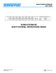
Model SCM810/M810E
User Guide
SCM810/SCM810E
EIGHT-CHANNEL MICROPHONE MIXER
©2005, Shure Incorporated
27C8504 (Rev. 8)
Printed in U.S.A.
TABLE OF CONTENTS
DESCRIPTION . . . . . . . . . . . . . . . . . . . . . . . . . . . . . . . . . . . . . . . . . . . . . . . . . . . . . . . . . . . . . . . . 3
SYSTEM FEATURES . . . . . . . . . . . . . . . . . . . . . . . . . . . . . . . . . . . . . . . . . . . . . . . . . . . . . . . 3
OPERATING PRINCIPLES . . . . . . . . . . . . . . . . . . . . . . . . . . . . . . . . . . . . . . . . . . . . . . . . . . 3
FRONT PANEL FEATURES . . . . . . . . . . . . . . . . . . . . . . . . . . . . . . . . . . . . . . . . . . . . . . . . . 4
REAR PANEL FEATURES . . . . . . . . . . . . . . . . . . . . . . . . . . . . . . . . . . . . . . . . . . . . . . . . . . . 4
DIP SWITCHES . . . . . . . . . . . . . . . . . . . . . . . . . . . . . . . . . . . . . . . . . . . . . . . . . . . . . . . . . . . 5
INSTALLATION AND SYSTEM SETUP . . . . . . . . . . . . . . . . . . . . . . . . . . . . . . . . . . . . . . . . . . . . 6
RACK MOUNTING THE MIXER . . . . . . . . . . . . . . . . . . . . . . . . . . . . . . . . . . . . . . . . . . . . . . 6
SCM810/E CONNECTIONS . . . . . . . . . . . . . . . . . . . . . . . . . . . . . . . . . . . . . . . . . . . . . . . . . . 6
OUTPUT LIMITER SETTINGS . . . . . . . . . . . . . . . . . . . . . . . . . . . . . . . . . . . . . . . . . . . . . . . . 6
EQUALIZER FUNCTIONS . . . . . . . . . . . . . . . . . . . . . . . . . . . . . . . . . . . . . . . . . . . . . . . . . . . 7
USING AN EQUALIZER/FEEDBACK CONTROLLER WITH AN AUTOMATIC MIXER . . . . 7
BASIC MIXER OPERATION . . . . . . . . . . . . . . . . . . . . . . . . . . . . . . . . . . . . . . . . . . . . . . . . . . . . . 7
NETWORKING MULTIPLE MIXERS . . . . . . . . . . . . . . . . . . . . . . . . . . . . . . . . . . . . . . . . . . . . . . . 8
GLOBAL/LOCAL FUNCTIONS . . . . . . . . . . . . . . . . . . . . . . . . . . . . . . . . . . . . . . . . . . . . . . . 8
LINK CABLES . . . . . . . . . . . . . . . . . . . . . . . . . . . . . . . . . . . . . . . . . . . . . . . . . . . . . . . . . . . . 8
SPECIFICATIONS . . . . . . . . . . . . . . . . . . . . . . . . . . . . . . . . . . . . . . . . . . . . . . . . . . . . . . . . . . . . . 9
ADVANCED FUNCTIONS . . . . . . . . . . . . . . . . . . . . . . . . . . . . . . . . . . . . . . . . . . . . . . . . . . . . . . 10
LOGIC CONNECTION SPECIFICATIONS . . . . . . . . . . . . . . . . . . . . . . . . . . . . . . . . . . . . . 10
SUGGESTED LOGIC APPLICATIONS . . . . . . . . . . . . . . . . . . . . . . . . . . . . . . . . . . . . . . . . 11
VOLTAGE SELECTION . . . . . . . . . . . . . . . . . . . . . . . . . . . . . . . . . . . . . . . . . . . . . . . . . . . . 13
INTERNAL MODIFICATIONS . . . . . . . . . . . . . . . . . . . . . . . . . . . . . . . . . . . . . . . . . . . . . . . 14
! IMPORTANT SAFETY INSTRUCTIONS !
1.
2.
3.
4.
5.
6.
7.
8.
9.
10.
READ these instructions.
KEEP these instructions.
HEED all warnings.
FOLLOW all instructions.
DO NOT use this apparatus near water.
CLEAN ONLY with dry cloth.
DO NOT block any ventilation openings. Install in accordance with the manufacturer's instructions.
DO NOT install near any heat sources such as radiators, heat registers, stoves,
or other apparatus (including amplifiers) that produce heat.
DO NOT defeat the safety purpose of the polarized or grounding-type plug. A
polarized plug has two blades with one wider than the other. A grounding type
plug has two blades and a third grounding prong. The wider blade or the third
prong are provided for your safety. If the provided plug does not fit into your outlet, consult an electrician for replacement of the obsolete outlet.
PROTECT the power cord from being walked on or pinched, particularly at plugs,
convenience receptacles, and the point where they exit from the apparatus.
11.
12.
13.
14.
15.
This symbol indicates that there are important operating and
maintenance instructions in the literature accompanying this unit.
ONLY USE attachments/accessories specified by the manufacturer.
USE only with a cart, stand, tripod, bracket, or table
specified by the manufacturer, or sold with the
apparatus. When a cart is used, use caution when
moving the cart/apparatus combination to avoid
injury from tip-over.
UNPLUG this apparatus during lightning storms or when unused for long periods of
time.
REFER all servicing to qualified service personnel. Servicing is required when the
apparatus has been damaged in any way, such as power-supply cord or plug is damaged, liquid has been spilled or objects have fallen into the apparatus, the apparatus
has been exposed to rain or moisture, does not operate normally, or has been
dropped.
DO NOT expose the apparatus to dripping and splashing. DO NOT put objects filled
with liquids, such as vases, on the apparatus.
This symbol indicates that dangerous voltage constituting a
risk of electric shock is present within this unit.
WARNING: Voltages in this equipment are hazardous to life. No user-serviceable parts inside. Refer all servicing to qualified service personnel. The
safety certifications do not apply when the operating voltage is changed from the factory setting.
2
DESCRIPTION
Each input channel has a two-band equalizer and three logic terminals. The
equalizer reduces unwanted low-frequency audio pickup and makes different microphone types-lavaliers, boundary and handheld-sound similar. The
logic terminals can be used to control external devices.
The Shure Model SCM810/E is an eight-channel automatic microphone
mixer designed for use in sound reinforcement, audio recording, and
broadcast applications. The SCM810 dramatically improves audio quality
in any application where multiple microphones are required. Any low-impedance dynamic or condenser microphone (including wireless) can be
used with the SCM810/E. Multiple SCM810 mixers can be linked to other
SCM810/E mixers, as well as to Shure Models FP410, SCM410, SCM800,
and AMS8100 mixers.
The SCM810/E operates on 100-120 Vac power; the SCM810E operates
on 220-240 Vac power. Each mixer is supplied with a power cord,
rack-mounting hardware, and a link cable.
SYSTEM FEATURES
•
•
•
•
•
•
Fast-acting, noise-free microphone selection that automatically
adjusts to changes in background room noise
Automatic gain adjustment as additional microphones are activated
Last Mic Lock-On circuit that maintains ambient sound
Adjustable low-frequency rolloff and high-frequency shelving for
each channel
Channel activation and clipping indicators
•
•
•
•
Peak-responding output limiter with selectable thresholds and
LED indicator
Active balanced microphone-level XLR inputs and an active balanced Mic/Line level XLR output
Aux-level input with manual level control
Front-panel headphones output with level control
Linking capability for up to 400 microphones
OPERATING PRINCIPLES
•
The operating concept behind the SCM810/E Automatic Mixer is Shure's
patented* IntelliMix® circuitry. IntelliMix delivers seamless automatic mixing
by combining three separate functions:
•
Noise Adaptive Threshold. Distinguishes between constant
background noise (such as air conditioning) and changing sound
(such as speech) for each input channel. It continuously adjusts
the activation threshold so that only speech levels louder than the
background noise activate a channel.
•
3
MaxBus. Controls the number of channels that may be activated
for a single sound source. One talker activates only one channel,
even if multiple microphones “hear” that talker.
Last Mic Lock-On. Keeps the most recently activated microphone open until another microphone is activated. Without Last
Mic Lock-On, a long pause in conversation would cause all microphones to turn off, which would sound as if the audio signal had
been lost. Last Mic Lock-On ensures that background ambience
is always present.
FRONT PANEL FEATURES
�
�
�
�
�
�
�
�
쐅
�
MODEL SCM810 FRONT PANEL
FIGURE 1
� Microphone Channel Gain Controls 1 - 8: Allows adjustment of
�
�
�
�
� Aux INPUT 1/4-inch Phone Jack: Mixes external auxiliary- or
microphone gain.
Input LED 1 - 8: Lights green when channel is active; lights red at 6
dB below clipping level.
Low-Cut Filter 1 - 8: Recessed screwdriver adjustment provides
adjustable low-frequency rolloff (high pass) to reduce undesirable
low-frequency signals.
High-Frequency Shelving Filter 1 - 8: Provides level boost or cut in
mid/high-frequency region to compensate for off-axis tone coloration,
or for cutting high-frequency sibilance.
AUX Level Control: Sets the input level for aux-level equipment connected to the adjacent 1/4-inch INPUT phone jack or rear-panel
1/4-inch AUX input.
�
�
�
쐅
line-level sources into output. This out is not automatic. Signal
appears at output of all linked mixers.
MASTER Level Control: Determines the overall mix level.
Output Level Meter: Nine-segment LED meter indicates peak output
signal level. Last LED indicates limiter action.
PHONES Control and 1/4-inch Phone Jack: Permits monitoring of
mixer output through headphones. The PHONES knob controls headphones output level.
POWER LED: Lights green when unit is powered.
REAR PANEL FEATURES
쐈
쐉
씉
씈
씌
씊
씍
씋
씎
SCM810 REAR PANEL
FIGURE 2
쐈 AC Power Connector and Rocker Switch: Connector supplies AC
씋 DIRECT OUT 1/4-inch Phone Jacks: Provides non-gated aux-level
power to unit when plugged into a power source: the rocker switch
turns the unit on.
signal from each channel. Direct outs are wired pre-fader and pre-EQ.
Can be modified for use as a gated channel output, send/receive
insert point, or external speech gate for mixing consoles (see Internal
Modifications section).
쐉 Microphone Logic: DB-25 male connector interfaces with each
channel's GATE OUT, MUTE IN, and OVERRIDE IN logic terminals.
See the Suggested Logic Applications section. NOTE: THIS IS NOT
AN RS-232 PORT.
씌 AUX/D.O./D.O. Switch: Located behind the Line Output connector,
this switch selects either aux input function or direct output function for
channel 8 Direct Out jack. Left switch position is AUX IN; center and
right positions are DIRECT OUT.
씈 DIP Switch: The 7-position DIP switch provides setup options for the
mixer (see DIP Switches section).
씉 LINK IN/OUT Jacks: Allow multiple mixers to be stacked for addi-
씍 INPUT 1-8 Removable Block Connectors: Active balanced micro-
씊 LINE OUTPUT Removable Block Connector: Active balanced
씎 Input 1 - 8 MIC/PHM/LINE Switch: Located behind the removable
phone- or line-level inputs.
tional inputs. Up to 50 SCM810 mixers can be linked.
block connector, this switch selects operation at either microphone-level (left), microphone-level with 48 V phantom power (center), or line-level (right) signals.
line-level signal for connection to amplifiers, recorders or other mixers.
Output can be modified to microphone level (see Internal
Modifications).
4
DIP SWITCHES
The rear-panel DIP switch provides the following setup options. The positions shown in bold type are the factory settings.
(MIXER
REAR
PANEL)
NOTE: Switch positions and effects are shown in Figure 3 and also on the
mixer label.
DIP
SWITCH
SW702
12 3 4 5 6 7
MODIFIABLE FUNCTION SWITCHES
FIGURE 3
DIP SWITCH SW702 FUNCTIONS
Switch
Function
Switch Position
Number→
Manual/Auto
Last Mic
Lock-On
Hold Time
Off-Attenuation
Level
Limiter
Threshold
Link
Local/Global
1
2
3
4
5,6
7
5 Up
6 Up
5 Down
6 Up
Switch Up
Auto
On
0.4 second
15 dB
5 Up
6 Down
5 Down
6 Down
Switch Down
Manual
All mics off after
hold time
1.0 second
∞ (completely off)
= Limiter off
= +8 dBm
Global
= +16 dBm
= +4 dBm
Local
Off-Attenuation: Changes the off-attenuation level from 15 dB to infinity
(∞). With the 15 dB setting, an unused microphone is 15 dB lower in level
than when it is activated. With the ∞ setting, an unused microphone is completely off.
Manual/Auto: Automatic activation is defeated in the Manual position. In
Manual mode, functions as a standard 8x1 mixer.
Last Mic Lock-On: Last Mic Lock-On feature keeps the most recently activated microphone turned on until a newly activated microphone takes its
place. When defeated, microphones turn off after their preset hold time.
Limiter Threshold: Changes the output limiter threshold. Settings are
OFF (factory setting), +16 dBm, +8 dBm, or +4 dBm (see Internal Modifications for other threshold settings).
Hold Time: Adjusts the time an activated microphone (which is not locked
on) remains on after the talker stops talking. Settings are 0.4 seconds or
1.0 second.
Link Global/Local: Determines whether each linked SCM810 output contains only its own program output, or that of all linked mixers (see Mixer
Linking for more information).
5
INSTALLATION AND SYSTEM SETUP
RACK MOUNTING THE MIXER
To mount the SCM810 in a standard 483 mm (19-inch) audio equipment
rack, slide the mixer into the rack and secure it with the supplied Phillips
head screws, as shown in Figure 4. Use all four screws.
RACK MOUNTING THE SCM810/E
FIGURE 4
SCM810/E CONNECTIONS
Make audio connections as follows (see Figure 5).
1. Connect microphone- or line-level signal sources to the Channel Input
connectors (use conventional 2-conductor shielded cables).
2. Insert a screwdriver or other tool in the slot above each block connector and adjust the input slide switch as required: microphone (left position), microphone with 48 V phantom power (center position), or line
level (right switch position).
3. Connect the SCM810 Line Level Output to the input of mixers, EQs,
amplifiers or recorders.
4. For headphones monitoring, connect headphones to the front-panel
1/4-inch PHONES jack.
5. Connect the power cord to 120 Vac (SCM810) or 230 Vac
(SCM810E). If the operating voltage is to be changed, refer to the
Internal Modifications section.
TO STEREO OR MONO HEADPHONES
FROM AUX– OR LINE–LEVEL SOURCE
TO AMP/REC/MIXER INPUT (CH. 1–7)
FROM MIC/LINE SOURCE (CH. 1–8)
TO AMP/RECORD/MIXER INPUT
OR FROM AUX SOURCE (CH. 8)
MIXER OUTPUT TO AMP/REC/MIXER INPUT
TO LINKED SCM810 MIXERS
TO ADVANCED FUNCTION WIRING
TO 120 VAC POWER SOURCE
AUDIO CONNECTIONS
FIGURE 5
OUTPUT LIMITER SETTINGS
Increasing the individual channel or Master Gain controls will increase the
average output and, in turn, the amount of limiting. As supplied, the output limiter is defeated. However, you can change the limiter threshold so
that the peak output level is +4, +8, or +16 dBm. Refer to the Internal Modifications section.
The output limiter prevents distortion during loud program peaks without affecting normal program levels. This prevents overloading of the devices
connected to the SCM810/E output.
6
EQUALIZER FUNCTIONS
Low Cut Filter (High-Pass)
The low-cut (or high-pass) filter allows all frequencies above its cutoff point
to pass from filter input to filter output without attenuation, while frequencies
below the cutoff are attenuated (see Figure 6). The cutoff point is defined
as the frequency where the signal has dropped 3 dB relative to the flat, or
bandpass, region. Below the cutoff point, the filter exhibits increasingly
more attenuation as the frequency diminishes. The rate at which this attenuation occurs is defined in decibels per octave (dB/oct). The SCM810 has
a one-pole, low-cut (high-pass) filter of 6 dB per octave.
+2
Low-cut filters are ideally used for attenuating, or rolling off, the audio signal
where extraneous noise, excessive proximity effect, or other unwanted material is present. For example, the low-frequency vibration cause by footsteps and vehicle traffic can be transmitted through microphone stands to
the microphone, and then into the sound system. These frequencies, typically ranging from 5 to 80 Hz, are generally not desirable.
-10
0
FULL CW
-2
-4
-6
FULL CCW
-8
50%
ROTATION
20
100
1,000
FREQUENCY (Hz)
5,000
LOW-CUT FILTER EFFECTS
FIGURE 6
+10
High-Frequency Shelving
FULL
CW
+8
+6
The fixed-frequency equalizer produces a 6 dB boost or cut at 5 kHz and
above (see Figure 7). High-frequency shelving is extremely useful for
boosting flat frequency response, tempering very sibilant vocal
microphones, or enhancing the sound of off-axis lavalier microphones.
+4
+2
50%
ROTATE
0
-2
-4
-6
-8
-10
200
FULL
CCW
1,000
10,000 20,000
FREQUENCY (Hz)
HIGH-FREQUENCY SHELVING EFFECTS
FIGURE 7
USING AN EQUALIZER/FEEDBACK CONTROLLER WITH AN AUTOMATIC MIXER
After equalizing the sound system, set the SCM810 to AUTOMATIC mode.
Remember that the input of an automatic mixer drops by 3 dB every time
the number activated inputs doubles. When using an SCM810 in MANUAL
mode, the master output drops by 9 dB when all 8 inputs are activated.
Conversely, it will rise by 9 dB when switched back to AUTOMATIC mode.
When setting up a sound system which has an outboard equalizer or feedback controller in the signal chain, set the SCM810 to MANUAL. This activates all microphone inputs, so every possible feedback path is open. With
the SCM810 in MANUAL mode, equalize the sound system and/or “Ring
Out” the room to set the feedback controller.
BASIC MIXER OPERATION
5. If a headphone monitor is to be used, adjust the PHONES control
knob until the desired volume level is reached.The SCM810/E is now
ready to use.
1. Turn on the Power switch.
2. Adjust each channel level so that its Overload LED flickers only during
very loud speech or noise.
3. Turn unused channel controls full counterclockwise.
4. Adjust the SCM810 Master level control for the required output level,
as indicated by the output peak meter.
NOTE: The SCM810/E mixer is fully automatic. For most applications, no
additional adjustments are required.
NOTE: The extreme sensitivity of the IntelliMix circuitry may allow some channel gating due to static discharge or electrical disturbance to the power
or signal lines. The unit will not be damaged: normal operation will resume after the disturbance ceases.
7
NETWORKING MULTIPLE MIXERS
As long as the link jacks of all mixers are connected (out-to-in, sequentially,
leaving one Link In and one Link Out jack unconnected), the automatic mixing functions will be shared by all units. All input signals appear at all linked
mixer outputs. There is no master/slave relationship.
If additional inputs are needed, more SCM810 mixers (as many as 50) can
be “linked” using supplied link cables. Such a configuration can provide up
to 400 microphone inputs.
To link multiple mixers, connect the LINK OUT of the first mixer to the LINK
IN of the next mixer, and so on (see Figure 8). Leave the LINK IN jack of
the first mixer and the LINK OUT jack of the last mixer unconnected.
The output controls and functions of each linked mixer are post-link and do
not affect the signals appearing at other linked mixer outputs. Each mixer's
Master level control only controls its own output. Each output can be used
independently.
REMARQUE : Ces jacks sont conçus pour le jumelage des mélangeurs uniquement et non pas pour les entrées ou sorties audio (se reporter à la figure 5).
NOTE: The actual off-attenuation in the 15 dB switch position increases as
more mixers are linked. This reduces excessive noise and reverberation
contributed by the increased number of attenuated microphones.
In a linked system, the Aux input of any mixer appears at each linked mixer's output. See Internal Modifications to defeat the linking of Aux signals.
IMPORTANT: When using the logic terminals on linked mixers, connect the
LOGIC GROUND terminals of each unit together. Switching clicks may result if this is not done.
LINKING MIXERS
FIGURE 8
GLOBAL/LOCAL FUNCTIONS
The Global/Local switch selects which input channels appear at that linked
mixer's output. Set to the Global position, all input channels appear at that
mixer's output. Set to the Local position, only its own eight input channels
appear at that mixer's output. The Master level control, in any mode, only
controls the level of its own output.
SCM810 “C” (GLOBAL)
The Master level control is independent of the Global/Local switch. The output level of each mixer is affected only by its own Master control. All automatic functions (such as Last Mic Lock-on and MaxBus) are connected on
all linked mixers and are not affected by the Global/Local switch.
LINK
Link Global/
Local Switch
Audio Output
Contains...
A
Local
A
B
Local
B
C
Global
A, B, C
SCM810 “A” (LOCAL)
SCM810 “B” (LOCAL)
An example of the possibilities of this setup is shown in Figure 9 Here two
SCM810s are set to Local, and the resulting sound distribution provides
local sound reinforcement while avoiding feedback. This is a simple
“mix-minus” setup. The third SCM810 is set to Global and feeds a tape
recorder, At the same time, the automatic functions (Last Mic Lock-On,
etc.) remain common to all mixers. The following table summarizes the
mixer settings.
MIXER
RECORDER
LOUDSPEAKER
LOUDSPEAKER
LINKED SCM810 MIXERS
FIGURE 9
LINK CABLES
connections; they are variously referred to by Apple as “shielded serial
cable with two mini DIN-8 connectors,” and “Apple System Peripheral-8
Cable.”
Additional link cables are available as Shure Part No. 95A1143 (305 mm12 in.). Longer cables in a variety of lengths are available from Apple Computer as computer printer
8
SPECIFICATIONS
Input Channel Activation
Attack Time 4 ms
Hold Time0.4 s (Switchable to 1.0 s)
Decay Time0.5 s
Off-Attenuation
15 dB (switchable to ∞)
Overload and Shorting Protection
Shorting outputs, even for prolonged periods, causes no damage. Microphone inputs are not damaged by signals up to 3 V; Line and Monitor
inputs by signals up to 20 V
Equalization
Low-frequency 6 dB/octave cut, adjustable
corner from 25 to 320 Hz
High-frequency±6 dB at 5 kHz, ±8 dB at
10 kHz, shelving
Limiter
Type Peak
Threshold Switchable: off, +4, +8, +16
(dBm at output)
Attack Time2 ms
Recovery Time300 ms
Indicator Lights red when limiting occurs
Input LEDs
Green on channel activation, red at 6 dB below clipping
Phantom Power
46 Vdc open-circuit through 6.8 kΩ series resistance per DIN 45 596
Operating Voltage
SCM810: 120 Vac rated nominal (see Voltage Selection for 230 Vac operation), 50/60 Hz, 200 mA
SCM810E: 230 Vac rated nominal (see Voltage Selection for 120 Vac
operation), 50/60 Hz, 100 mA
Temperature Range
Operating0° to 60° C (32° to 140° F)
Storage-30° to 70° C (-20° to 165° F)
Overall Dimensions
44.5 mm H x 483 mm W x 317 mm D
(1 3/4 x 19 x 12 1/2 inches)
Net Weight
4.3 kg (9 lb 9 oz)
Certifications
Measurement Conditions (unless otherwise specified): Line voltage 120
Vac, 60 Hz (SCM810) or 230 Vac, 50 Hz (SCM810E); full gain; 1 kHz, one
channel activated; source impedances: Mic 150 Ω, Line 150 Ω; terminations: Line 10 kΩ, Phones 300 Ω (tip-sleeve and ring-sleeve), Direct Out 10
kΩ; Auto mode, equalization controls adjusted for flat response
Frequency Response (Ref 1 kHz, channel controls centered)
50 Hz to 20 kHz ±2 dB; -3 dB corner at 25 Hz
Voltage Gain (typical, controls full clockwise)
Output
Line
Headphones
Direct Out
Low-impedance
mic (150 Ω)
80 dB
88 dB
34 dB
Line
40 dB
48 dB
-6 dB
Aux
44 dB
52 dB
-
Send/Return
20 dB
28 dB
-
Input
Inputs
Impedance
Input
Designed for
use with
Actual
(typical)
Input
Clipping
Level
Mic
19-600 Ω
1.6 kΩ
-15 dBV
Line
≤2 kΩ
10 kΩ
+22 dBV
Aux
≤2 kΩ
10 kΩ
+22 dBV
Send/Return
≤2 kΩ
10 kΩ
+18 dBV
Outputs
Impedance
Output
Designed for
use with
Actual
(typical)
Output
Clipping
Level
Line
>600 Ω
60 Ω
+18 dBV
Headphones
8-200 Ω,
60 Ω
recommended
300 Ω
+12 dBV
Direct Out
>2 kΩ
1 kΩ
+18 dBV
Send/Return
>2 kΩ
1 kΩ
+18 dBV
SCM810: Listed by Underwriters Laboratories, Inc., listed as Certified by
Canadian Standards Association; SCM810E: Conforms to European Union
directives, eligible to bear CE marking; VDE GS-Certified to EN 60 950;
meets European Union EMC Immunity Requirements (EN 50 082-1, 1992).
Replacement Parts
Block Connector ....................................................................... 95A8580
Knob, Master & Phones (white) ................................................ 95A8238
Knob, Channel Gain (blue) ....................................................... 95B8238
Line (Power) Cord (SCM810) ..................................................95A8389*
Line (Power) Cord (SCM810E)................................................95A8247*
Link Cable................................................................................. 95A8889
Total Harmonic Distortion
<0.1% at +18 dBV output level, 50 Hz to 20 kHz (through 20 Hz-20 kHz
filter; Input 1 and Master at 5, all other controls full counterclockwise)
Hum and Noise
Equivalent Input Noise . . . . . . . . . . . . . . . . –125 dBV (150 Ω source;
through 400 Hz –20 kHz filter)
Equivalent Input Hum and Noise:
. . . . . . . . . . . . . . . . . . . . . . . . . . . . –123 dBV (150 Ω source; through
20 Hz - 20 kHz filter)
*For systems requiring other mains connectors, obtain a power cord
with an IEC 320 type mating connector for connection to the SCM810,
and an appropriate plug on the other end for connection to the mains.
The supplied cord uses Harmonized IEC Cordage with color coding
as follows: Brown = Line, Blue = Neutral, Green/Yellow = Ground.
Output Hum and Noise (through 20 Hz to 20 kHz filter; channel controls
full counterclockwise))
Master full counterclockwise . . . . . . . . . . . . . . . . . . . . . . . . . –90 dBV
Master full clockwise . . . . . . . . . . . . . . . . . . . . . . . . . . . . . . . –70 dBV
Common Mode Rejection
>70 dB at 1 kHz
Polarity
Mic/Line, Send inputs to all outputs are non-inverting; Aux input to all
outputs is inverting
9
ADVANCED FUNCTIONS
The SCM810's Advanced Functions are recommended only for those who are technically knowledgeable and familiar with audio
electronics.
LOGIC CONNECTION SPECIFICATIONS
Logic controls are accessed at the DB-25 multi-pin connector on the rear
panel (Figure 11). The pin connections are given in the following table.
The logic functions of the SCM810 expand the mixer's range of installation
and control options. Logic can be used for everything from simple cough
switches to elaborate computer-controlled room systems. (Shure's AMS
Update publication contains additional applications of advanced logic. This
publication is available by contacting Shure's Applications Group.) The following logic functions are available for each channel:
GATE 1
GATE 3
GATE 5
GATE 7
LOGIC
MUTE 1
MUTE 3
MUTE 5
MUTE 7 GROUND
O’RIDE 2
O’RIDE 4
O’RIDE 6
O’RIDE 8
GATE OUT: Follows channel gating and goes to logic “low” (sinks current)
when microphone is gated on. 500 mA of current sinking ability is provided
(see Figure 10A).
+5 V
+5 V
MUTE 2
55K
10K
GATE
OUT
MUTE IN
OR
OVERRIDE
IN
MUTE 4
MUTE 6
MUTE 8
GATE 2
GATE 4
GATE 6
GATE 8
O’RIDE 1
O’RIDE 3
O’RIDE 5
O’RIDE 7
TO
SCM810
CIRCUIT
LOGIC CONNECTOR
FIGURE 11
FROM
SCM810
CIRCUIT
LOGIC CONNECTIONS
LOGIC
GROUND
A
B
LOGIC EQUIVALENT CIRCUIT DIAGRAMS
FIGURE 10
MUTE IN: Applying logic “low” (from GATE OUT or a switch closure to logic
ground) gates channel off (see Figure 10B). Channel output drops to -∞.
OVERRIDE IN: Applying logic “low” (from GATE OUT or a switch closure
to logic ground) forces channel on (see Figure 10B). Factory setting provides that when both Mute and Override are activated, Mute takes precedence (see Internal Modifications for Override precedence).
LOGIC GROUND: Logic ground is distinct from the SCM810 audio ground.
Make all logic ground connections to this pin, including power supply
ground of external logic circuitry. To avoid switching clicks, do not connect
logic ground to audio, chassis or rack grounds.
10
Logic Function
Input
Channel
Connector Pin No.
GATE OUT1
GATE OUT 2
GATE OUT 3
GATE OUT 4
GATE OUT 5
GATE OUT 6
GATE OUT 7
GATE OUT 8
1
2
3
4
5
6
7
8
1
15
4
18
7
21
10
24
OVERRIDE IN 1
OVERRIDE IN 2
OVERRIDE IN 3
OVERRIDE IN 4
OVERRIDE IN 5
OVERRIDE IN 6
OVERRIDE IN 7
OVERRIDE IN 8
1
2
3
4
5
6
7
8
14
3
17
6
20
9
23
12
MUTE IN 1
MUTE IN 2
MUTE IN 3
MUTE IN 4
MUTE IN 5
MUTE IN 6
MUTE IN 7
MUTE IN 8
1
2
3
4
5
6
7
8
2
16
5
19
8
22
11
25
Logic Ground
all
13
SUGGESTED LOGIC APPLICATIONS
Remote Channel-On Indicators
This section contains suggestions on the uses of the SCM810's logic capabilities. Note that uses of these functions are not limited to the listed applications. The user is limited only by individual imagination and creativity. For
additional suggestions and solutions to installation problems, contact
Shure's Applications Group.
Remote indicators can be used to indicate when a talker's microphone is
on. Connect the LEDs and a 5-volt supply to the GATE OUT pins as shown
in Figure 14 (Channels 1, 2 and 3 shown modified). To avoid switching
clicks in the audio output, do not ground the power supply negative terminal
in the audio system or rack ground.
In the following paragraphs, the wiring diagrams refer to the DB-25 connector pins shown in Figure 4.
IMPORTANT: If a single cable is used for the microphone audio signal and
the LED dc power, separate shielded pairs must be used. Failure to carry
the dc power on a shielded pair may result in audible clicking due to capacitive coupling between the dc power lines and microphone lines.
Cough Button
The talker can turn off his or her microphone during coughing or private
conversations by installing an SPST pushbutton switch between the MUTE
IN and Logic Ground pins for each channel to be modified (see Figure 12Channels 1, 2 and 3 modified). When a channel is muted, no audio is
passed. (See “Dead Zone on MUTE IN Defeat” in Internal Modifications
section for more information on MUTE IN logic.)
+
5 V POWER –
SUPPLY
LOGIC
GROUND
LOGIC
GROUND
M1
G1
G3
M3
G2
R = 470 &!, 1/4 W
M2
REMOTE CHANNEL-ON INDICATORS
FIGURE 14
COUGH BUTTONS
FIGURE 12
Disabling the Gating Function (Bypass)
To keep certain microphones on at all times, wire the desired microphone
channel's OVERRIDE IN pins together to the Logic Ground pin. The
selected channels now function as they would in a non-automatic mixer
(see Figure 15-Channels 1, 2 and 3 modified).
Chairperson-Controlled Muting
The chairperson can, by activating a switch, silence all other microphones
and be heard without interruption. For operation in this mode, connect all
the MUTE IN pins together except that of the chairperson's channel, and
wire an SPST pushbutton or toggle switch between those MUTE IN and
Logic Ground pins (see Figure 13-the chairperson is shown as Channel 1).
LOGIC
GROUND
O2
An alternative to a switch is to connect the chairperson's GATE OUT to the
MUTE IN of other channels. When the chairperson's microphone activates,
all other microphones mute.
O1
CH. 1
M3
M2
M4
M5
M7
LOGIC
GROUND
O3
GATING BYPASS
FIGURE 15
M6
CHAIRPERSON-CONTROLLED MUTING
FIGURE 13
11
Inhibiting Gating for Unwanted Sounds
As described in the Operating Principles section, MaxBus attempts to activate only one microphone per sound source. Muting a microphone channel
prevents its audio from appearing at the mixer's output. However, the muted microphone still communicates with other mic channels via MaxBus. A
sound source picked up by a muted microphone will not activate other microphones.
+
12 V
POWER
SUPPLY
–
Sound sources that may cause unwanted microphone channel activation
include:
•
A noisy fax machine or printer
•
A squeaky door
•
A paging system loudspeaker
•
An audio teleconferencing return signal loudspeaker
The SCM810 can prevent these and similar sounds from activating microphones by taking the following steps.
1. Place one microphone near the unwanted sound source. Connect that
microphone's signal to a channel input,
-orconnect the unwanted sound source directly into a Mic/Line channel
input.
2. Mute that channel using the logic terminal (see Figure 16-Channel 1 is
muted).
3. Adjust that channel's gain control just to the level where other microphones in the system do not activate for the unwanted sound. If the
channel gain is set too high, other system microphones will be difficult
to activate for desired sounds. If set too low, unwanted sounds will
continue to activate other microphones.
ÑÑ
ÑÑÑÑÑÑÑÑÑ
ÑÑ
ÑÑÑÑÑÑÑÑÑ
LOGIC
GROUND
ÑÑ
Ñ
ÑÑÑÑÑÑÑÑ
ÑÑ
Ñ
ÑÑÑ
ÑÑÑ
ÑÑÑÑÑÑÑÑÑÑ
ÑÑÑÑÑÑÑÑÑÑÑ
G3 G5
G1
D = 1N4148
FROM
POWER
AMP
LOUDSPEAKER MUTING
FIGURE 17
“Filibuster” Mode
In normal operation, when several people talk, each microphone gates on
so that no speech is missed. In “filibuster” action, a microphone that is gated on prevents other microphones from gating on. Once a microphone has
gated on, other microphones cannot gate on until the talker has paused
long enough for that microphone to gate off. Thus the person talking has
the floor and cannot be interrupted.
LOGIC
GROUND
M1
To establish this function, first perform the internal Mute to “Inhibit” modification (see Internal Modifications). Then connect all the MUTE IN pins of
the modified channels together, all the GATE OUT pins of the modified
channels together, and the GATE OUT pin of one modified channel to the
MUTE IN pin of another modified channel (see Figure 18-Channels 1, 2
and 3 modified). Turn the Last Mic Lock-On switch (SW702, position 2) to
off.
INHIBITING GATING UNWANTED SOUNDS
FIGURE 16
Loudspeaker Muting
Some applications require a loudspeaker to be placed near each talker to
provide audio reinforcement, or to permit telephone conversation or
conference monitoring. Each loudspeaker can cause feedback unless it is
automatically switched off when the talker near it speaks. To provide this
function, connect the GATE OUT terminal of each channel to a separate
loudspeaker muting relay as shown in Figure 17 (Channels 1, 3 and 5
shown modified). Recommended relays are Omron G6B-1174P-US-DC12,
Potter & Brumfield R10-E1Y2-V185, or equivalent (available through
Digi-Key and Newark Electronics).
NOTE: To prevent high-frequency oscillation, do not wire a channel's GATE
OUT pin to its own MUTE IN pin unless the Mute to “Inhibit” change has
been made.
G3
M1 M3
G1
JUMPER
NOTE: A diode across each relay coil is required to suppress inductive voltage spikes which may damage the SCM810.
An existing sound system using 24-volt relays can be used with the
SCM810 without modification if the relay coil current draw is under 500 mA.
G2
M2
“FILIBUSTER” MODE
FIGURE 18
Inhibit Function
See Internal Modifications.
12
LOGIC
GROUND
Diode Isolation of Logic Controls
Mixer logic may be used with 15-volt CMOS logic if a pull-up resistor is
used with each GATE output (see Figure 20-Channel 1 modified).
Two or more control functions using the same logic pins can be isolated
with diodes. In this manner a channel can be muted by an overall group
mute switch, or by its own cough button (see Figure 19-Channels 1, 3 and
5 modified).
+
15 V
POWER
SUPPLY
5.1 K
–
D = 1N4148 OR
EQUIVALENT
GROUP
MUTE
ÑÑÑÑÑÑÑÑÑ
Ñ
Ñ
ÑÑÑÑÑÑÑÑÑ
Ñ
ÑÑÑÑÑÑÑÑÑ
M1
M3
M5
CMOS
GATES
LOGIC
GROUND
LOGIC
GROUND
G1
M1
COUGH
BUTTONS
O1
15-VOLT CMOS
FIGURE 20
DIODE ISOLATION OF LOGIC CONTROLS
FIGURE 19
External Logic Devices
Digital Controls or Microcomputers
SCM810 logic levels are directly compatible with TTL and 5-volt CMOS logic families. For information on logic gate use, refer to the TTL Cookbook
and CMOS Cookbook, both by D. Lancaster, Howard Sams Publishing Co.
The SCM810 logic pins can interface with custom-designed digital control
circuitry or microcomputers for unlimited possibilities of system control
functions.
VOLTAGE SELECTION
5. Replace the power cord with a cord rated for 230 V operation, i.e., an
IEC appliance connector on the equipment end and a CEE 7/7
(“Schuko”) mains connector on the other.*
The SCM810 can be internally modified to operate from 230 Vac, 50/60 Hz
power.
WARNING: Voltages in this equipment are hazardous to life.
No user-serviceable parts inside. Refer all servicing to qualified
service personnel. The safety certifications of the SCM810 do not
apply when the operating voltage is changed from the factory
setting.
Similarly, the SCM810E can be internally modified to operate from 120 Vac,
50/60 Hz power.
*For systems requiring other mains connectors, obtain a power cord
with an IEC 320 type mating connector for connection to the SCM810,
and an appropriate plug on the other end for connection to the mains.
The supplied cord uses Harmonized IEC Cordage with color coding as
follows: Brown = Line, Blue = Neutral, Green/Yellow = Ground.
To change the operating voltage, follow these steps.
1. Disconnect the SCM810 from the AC power source.
2. Remove the eight Phillips head screws securing the top cover.
3. Locate Voltage Selector switch SW903 adjacent to power transformer
T901 and, using a screwdriver, turn the center rotor to the 230 V position.
4. Locate Fuse F901 and remove it. Replace it with a 100 mA, 250 V,
time delay fuse for 230-volt operation (200 mA, 250 V, slow-blow fuse
for 120-volt operation).
Fuse part numbers are:
Fuse Type
Shure Part No.
Whitefishes Part
No.
100 mA, 250 V
80C258
218.100
200 mA, 250 V
80BC8196
239.200
13
INTERNAL MODIFICATIONS
3. For individual channel modifications, the first number of the reference
designation refers to its channel number, i.e., R1027 refers to a Channel 1 resistor, X7216 refers to a Channel 7 jumper, etc. All references
to Channels 1 through 8 in the following paragraphs use Channel 1
jumpers and resistors as reference. Modifications affecting the Master
section are preceded by the number “9" (X901, etc.).
WARNING: All modifications must be performed by qualified service technicians.
This section describes SCM810 modifications that can be made using solder “jumpers” on the printed circuit board; the pads where jumpers may be
used are placed close together so that a single solder drop functions as a
jumper. Note too that:
1. he only printed circuit board legends used for these modifications are
jumpers (X's) and resistors (R's).
2. Where resistors are to be added, through-holes are present on the
board.
To gain access to the main printed circuit board, remove the 8 Phillips head
screws securing the top cover, and remove the top cover. Most modifications can be made from the top of the main board.
Line-Level Output to Mic-Level Output
Procedure: Short jumper X901. Remove resistors R900 and R909.
Disable Master Level Control
The Master gain control can be disabled so it cannot be tampered with. The
table indicates the resistor value to be used for the desired gain.
Master Section Gain
Resistance
-6 dB
5.1 kΩ
0
10 kΩ
6 dB
20 kΩ
Procedure: Remove resistor R9230. Install new resistor at jumper X914.
Change Limiter Threshold
Procedure: Remove resistors R9177 and R9180. Install new resistor R at
jumper X907.
All three threshold settings (+16, +8 and +4 dBm) can be changed. To shift
the threshold down by 6 dB, resistor R will be 82 kΩ. To shift the limiter
thresholds up by 6 dB, R will be 330 kΩ.
Local Aux Operation
With linked mixers, the Aux input from a modified mixer does not link.
Procedure: Remove resistor R9024.
Direct Out to Post-Fader
A channel's Direct Out phone jacks can be changed from pre- to post-fader.
Procedure: Short jumper X106. Remove resistor R1011.
Direct Out to Post-Fader Send/Return (Insert)
Procedure: Short jumpers X101, X102, X105 and X106. Remove resistors
R1011 and R1020.
Changes a channel's 1/4-inch Direct Out jack to a post-fader insert point.
Send is tip of phone jack; return is ring. Insert jacks are useful for inserting
line-level signal processors into a channel. For instance, a parametric EQ
or compressor/limiter can be inserted into a channel for additional processing.
Direct Out to Gated Direct Out
Procedure: Short jumpers X104 and X906 (in Master section). Remove resistor R1011.
This post-fader, post-EQ channel output is gated, but without NOMA. In this
mode, if the Local/Global switch is in “Local”, a manual mix of channel inputs is present at the Line output. The Off-Attenuation level of the Gated
Direct Out signal is infinite.
14
SCM810 Speech Gate for Mixing Console
The SCM810 can be used in conjunction with large mixing consoles to provide automatic mixing for talk shows, panel discussions, and news shows.
Large consoles have channel insert jacks so that external signal processing devices can be patched into individual channel signal paths. With this
modification the SCM810 can be placed into unbalanced insert jacks, and
the SCM810 used as a high-quality, external, 8-channel speech gate. This
arrangement allows the operator complete control of each channel via the
console's input control strip, while the SCM810 keeps the number of open
microphones to a minimum.
Procedure: Short jumpers X103, X107, X108 and X906 (in the Master section). Remove resistors R1011, R1019, and R1020.
In this operational mode:
1. The Direct Out jack tip is the input from the mixing console, and the
ring is the output to the mixing console.
2. The SCM810 channel inputs, faders and EQ do not function.
3. NOMA does not function, channel Off-Attenuation is infinite.
4. The front-panel channel overload indicators indicate gating and overload for each input.
5. The “Local” operating mode provides a non-automatic audio signal at
the output for use in external mixes.
6. If the insert point on the mixing console is pre-fader, the gain trims
should be set such that all microphone levels are similar.
MUTE IN Precedence to OVERRIDE IN Precedence
Procedure: Short jumper X114. Remove resistor R1046.
With this modification and when both MUTE IN and OVERRIDE IN logic are
grounded for a channel, the Override mode will take precedence (as supplied, the MUTE IN takes precedence over OVERRIDE IN).
Dead Zone on MUTE IN Defeat
Procedure: Short jumper X115.
As supplied, MUTE IN is intended for use as a momentary cough button or
privacy function (mute when necessary). However, if the MUTE IN is intended to be used so that the talker must unmute microphones to enable
speech pickup (unmute when needed), this modification is needed. This removes the muted channel from the MaxBus which eliminates “dead zones.”
A dead zone is an area in which a microphone picks up a talker through a
muted microphone and other microphones do not activate for that talker.
Change MUTE IN to Inhibit
Procedure: Short jumper X111.
As supplied, a channel will mute when its MUTE IN terminal is grounded.
The mute function can be changed to “Inhibit” by an internal modification
for each channel. After the modification, a logic “Low” at the MUTE IN terminal prevents that channel from gating on if it is off, but allows it to remain
on if it is already on.
IMPORTANT: To prevent high-frequency oscillation, never connect a
channel's GATE OUT to its own MUTE IN unless the “Inhibit” modification
has been made.
Change OVERRIDE IN to MUTE IN for Use with Filibuster Mode
This modification should only be performed with the Change MUTE IN to
Inhibit modification described above.
Procedure: Short jumper X113. Remove resistors R1046 and R1058.
Change Off-Attenuation Level
This modification changes the off-attenuation level from -15 dB to a selected value. Select from the following resistor values.
Off-Attenuation Level
Resistor Value
10 dB
18 kΩ
20 dB
50 kΩ
30 dB
150 kΩ
Procedure: Remove resistors R9088 and R9145. Install new resistor at
jumper points X904 and X908.
15
Increase Hold Time
Procedure: Install a 470 kΩ resistor across jumper points X902. Move DIP
switch down to 1.0-second position.
In addition to the dip switch SW702 options of 0.4- and 1.0-second hold
time, the hold time can be increased to 1.5 seconds. (More than 1.5 seconds is not recommended.)
Decrease Hold Time
The hold time can be decreased from the factory preset of 0.4 seconds to
0.3 seconds. (Less than 0.3 seconds is not recommended.)
Procedure: Install a 2 MΩ resistor at jumpers X903.
Remote Control of Link Global/Local, Off-Attenuation, Last Mic Lock-on,
and Automatic/Manual DIP Switches
If desired, these functions can each be remotely controlled with an SPST
switch.
Procedure:
1. Solder a wire in the pc board jumper hole adjacent to the desired function (printed on the printed circuit board). These jumpers are located
just behind DIP switch SW902.
2. Solder a wire in the pc board jumper hole marked “GND” near switch
SW902.
3. Set the desired DIP switch(es) to the Up position.
4. Run the jumper wires to the desired remote location and solder them
to an SPST toggle switch. The wires can exit the SCM810 chassis
above the DIP switches. Shorting any wire to the Ground wire will set
the function(s) to the corresponding switch “down” position.
SHURE Incorporated http://www.shure.com
United States, Canada, Latin America, Caribbean:
5800 W. Touhy Avenue, Niles, IL 60714-4608, U.S.A.
Phone: 847-600-2000 U.S. Fax: 847-600-1212 Intl Fax: 847-600-6446
Europe, Middle East, Africa:
Shure Europe GmbH, Phone: 49-7131-72140 Fax: 49-7131-721414
Asia, Pacific:
Shure Asia Limited, Phone: 852-2893-4290 Fax: 852-2893-4055
16