1
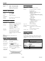
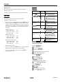
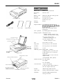
ES-800C
Scanner Specifications
Scanner main unit
Scanner type:
Flatbed, color/monochrome
Photoelectric
device:
CCD line sensor
Effective pixels:
3400 dots by 4680 dots at 400 dpi, 100%
Maximum
document size:
216 mm by 297 mm
(8.5 inches by 11.7 inches)
US letter size or A4
Scanning
resolution:
400 dpi
Output resolution: 50, 72, 75,80,90,100,120,133,144,
150,160,175,180,200,216,240,300,320,
360,400,480,600 and 800 dpi.
User’s Guide
Power cable
Image Sample
Values above 400 through software
interpolation.
Color separation:
By switching light sources (G, R, B)
Reading sequence: Monochrome mode:
One-time scanning (Dropout color
selectable from Green, Red, or Blue.)
Color page sequence mode:
Three-time scanning (G, R, B)
Document cover
Color line sequence mode:
One-time scanning (G, R, B)
Carriage (at home p
Document table
\
ERROR light
READY light
POWER light
Size:
50% to 200% in 1% steps.
Image data:
8 bits per pixel per color maximum
Gradation:
8 bits per pixel per color maximum
Brightness:
7 levels
Halftoning process: Enable/disable
POWEli switch
‘RESET switch
(Halftoning mode A only in color line
sequence mode)
Transportation screw
Option control connector
selectable.
3 halftoning modes (A, B, and C) and
4 dither patterns (A, B, C, and D) for
bi-level data
/
(2 downloadable dither patterns)
Gamma correction: 2 for CRT display
3 for printer
1 for user defined
Color correction:
Ground termina
SCSI ID rotary switch
SCSI interface connectors
Scanners
1 type for CRT display
3 types for printer output, available in
color line sequence mode only
Interface:
Bidirectional parallel and SCSI
Light source:
Noble gas fluorescent lamps (3 lamps)
Reliability:
Main unit: MCBF 100,000 cycles of
carriage movement
11&I92
ES-800C-1
ES-800C
Dimensions and
weight:
Width: 368 mm (14.5 inches)
Depth: 577 mm (22.5 inches)
Height: 161 mm (6.5 inches)
Weight: about 12 kg (26 lbs)
SCSI Specifications
Interface type:
ANSI X3.131-1986 standard
Function:
The following functions are included.
BUS FREE phase
ARBITRATION phase
SELECTION/ RESELECTION phase
COMMAND phase
(Logical Unit number is fixed to 0 and
command link function is not supported.)
DATA phase
Data in phase
Data out phase
STATUS phase
MESSAGE phase
(Includes MESSAGE IN phase and
MESSAGE OUT phase)
ATTENTION condition
RESET condition
Electrical Specifications
Voltage:
120 VAC, flO%
Frequency:
49.5 to 60.5 Hz
Power
consumption:
Approx. 50 W (max)
Insulation
resistance:
20 m between AC power line and
chassis at 500 VDC
Environmental Conditions
Temperature:
Humidity:
Operation: 40” F to 95” F (5” C to 35” C)
Storage: 10’ F to 150” F (-20” C to 60” C)
Logic level:
Operation: 30% to SO%, without
condensation
Electrical standard: As per ANSI X3.131-1986
Storage: 20% to 85%, without
condensation
Operating
conditions:
Ordinary office or home conditions.
Extreme dust should be avoided.
Operation under direct sunlight
or near a strong light source should be
avoided.
Note:
Specijcations are subject to change without notice.
Parallel Interface Specifications
Interface type:
Bidirectional parallel interface
Data format:
S-bit parallel
Synchronization:
By external strobe pulse
Handshaking:
By ACKNLG and BUSY signals
Logic level:
Input/output data and interface control
signals are TTL level compatible
Connector type:
36-pin Centronics@ type connector
TTL level compatible
ID Setting:
Selectable from 0 to 7 with the rotary
switch.
(8 and 9 should not be selected.)
Connector type:
Two 50-pin connectors
Scanning Functions
Scanner settings
The table below summarizes the scanner functions and the
settings available on your scanner. All of these functions are
controlled by the software commands from your scanner
software.
Function
Resolution
Size
Available settings
23 settings from 50 to 800 dpi
50% to 200% at 1% step
Color line sequence mode, color page sequence
mode and monochrome mode (dropout color
Gamma correction
Color correction
4 dither patterns
5 settings for output devices
4 settings for output devices
Connector pin
arrangement:
18
36
ES-800C-2
11/2/92
Scanners
ES-800C
Resolution guidelines
Problems and Solutions
This table shows the recommended resolutions in dots per
inch or pixels per inch for the image types and printing
methods. Also, you may want to experiment with your
scanner settings, possibly using a cropped version of your
image to save time, until you achieve the desired results.
Line art
Black and white printer
Electroniccolor printer
Printing presu’lmagesetter
Gray scale
300-400 7 5
150-200
300-400
400-800
150-200
Color
75
150-200
150-200
Data format
The problems you may have while using the scanner often
involve the operation of your software and computer.
Problems fall in the following major categories:
Ll Incorrect setup of the interface
CI Inappropriate selection of the scanner functions
Ll Incorrect setup of your computer or software
Cl Incorrect operation of your software.
Scanner errors
If an error occurs, the scanner stops operating and the READY
and ERROR lights show the type of error.
~~
Command error
Initialization
The scanner received incorrect commands from your
scanning software.
The scanner can be initialized (returned to a fixed set of
conditions) in three ways.
When this error occurs, try the scanning operation with your
software over again. The scanner returns to normal when it
receives correct commands. Normally you do not need to
reset the scanner.
Hardware initialization:
0 When the power is turned on.
Ll When the scanner receives an INIT signal at the parallel
interface (pin 31 goes low).
Software initialization:
Ll When the software command ESC 62 (initialize the
scanner) is received.
Default settings
The table below shows the default conditions when the
scanner is initialized.
Item
1 Default
Data format
Resolution
Size
Reading area
Color mode
1 bit/pixel/color
1 100 dpi
1100%
1850 x 1170 dots, no offset
1 Monochrome (standard)
When the scanner is initialized, the scanner terminates the
scanning operation, and the carriage returns to the home
position (rear of the scanner).
Scanners
Interface error
The interface setup is wrong, or the scanner is not properly
connected to the computer.
When this error occurs, check the interface connection. Push
the RESET button or turn the scanner off and then back on to
reset it.
Fatal error
This indicates one of the following problems:
One or more fluorescent lamps needs to be replaced.
The transportation screw is not released.
The scanner is broken.
There is a problem, such as an open cover, with the
optional automatic document feeder.
Check that the transportation screw is released and check the
automatic document feeder; then push the RESET button. If
the scanner still does not operate properly, try turning the
scanner off and then back on. If the scanner still does not
operate properly, or if this error occurs repeatedly, consult
your dealer.
1112i92
ES-800C-3
ES-800C
Option error
This indicates a problem such as a paper jam with an
installed option unit.
Check the option unit and correct the cause of the trouble.
Self Test
To run the self test, follow the instructions below:
1. Set the SCSI ID switch to 8.
2. Turn on the power while holding down the RESET button.
Continue holding the RESET button until initialization is
complete. (It takes approximately 10 seconds for self test
initialization to complete. Watch for the LEDs to change in
the sequence described below to tell that initialization is
complete.)
Just after power on:
Power LED (green) - O N
Ready LED (green) - O F F
Error LED (red)
- OFF
After a few seconds:
Power LED (green) - O N
Ready LED (green) - O N
Error LED (red)
- OFF
Options
1 Product
Number
Automatic Document 8813011
Feeder (ADF)
Option Name
1 Description
Feeds up to 30 sheets. Replaces
scanner cover, but still allows
scanning of individual items.
Transoarencv Unit
1 8813021
1 Allows scanning of slides,
negatives. and transparencies.
Replaces scanner cover, but still
allows scanning of individual
items. Allows scanning of items up
to 5”x 5”.
Includes bidirectional parallel
BIDIDOS
Bidirectional Parallel
board for the PC, cable, TWAIN
Interface Kit
scanner driver, and image editing
software.
Includes SCSI board for the PC,
SCSIDOS
SCSIDCX Interface
cable, TWAIN scanner driver, and
Kit
image editing software.
1 ESMAC
1 Includes scanner Plug-In Module
Mac Interface Kit
(PIM) and Desk Accessory (DA),
cable, Epson Apple Scanner
Driver, and image editing software.
Bidirectional Parallel 1 8808012 1 Available separately from kit for
customers who already have
Interface Board for
scanning software. Provides a
the PC
bidirectional port in the PC to
connect to the parallel interface in
the scanner.
Available separately from kit for
Bidirectional Parallel Cl-SE-A
customers who already have
Cable
I scanningsoftware.
I BO1901 I
I Scanner.
ES-8OOC
.~
I I
I
After a few more seconds:
Power LED (green) - O N
Ready LED (green) - O F F
Error LED (red)
- O N
Interface Kit Contents
Finally, all LEDS are lit
BIDIDOS interface Kit
3. You can now release the RESET button. The self test mode
begins, and the scanner operates automatically.
J Picture Publisher 3.1
4. You can stop the self test either by pressing RESET or
turning the power off.
Q TWAIN Scanner Driver
U Caere OCR TryPack
Cl Bidirectional Interface Board for the PC
0 Bidirectional Parallel Cable
SCSIDOS Intetfkce Kit
U Picture Publisher 3.1
U Caere OCR TryPack
3 TWAIN Scanner Driver
3 SCSI Interface Board for the PC
U SCSI Cable (50-pin to 50-pin)
ESMAC Intetface Kit
Ll Adobe Photoshop 2.0
0 PIMand DA
Q Epson Apple Scanner Driver
Cl SCSI Cable (50-pin to 25-pin)
ES-800C-4
11 f2f92
Scanners
ES-800C
Information Reference List
Engineering Change Notices
None
Product Support Bulletins
None
Technical Support Bulletins
None
Related Documentation
TM-ES800C
ES-80OC Service Manual
PL-E!%OOC
E%OOC Parts Price List
SPKESSOOC
EW3OOC Self Paced Kit
4001696
E!%OOC User’s Guide
TM-B813021
Transparency Unit Service Manual
PL-B813021
Transparency Unit Parts Price List
SPKB813021
Transparency Unit Self Paced Kit
Scanners
1 l/2/92
ES-800C-5