1
®
ScanVue5 Mini Kiosk
User Manual
M37574–01T
Industrial Electronic Engineers, Inc.
ScanVue5®
User Manual
(U.S. Patent No. 6,213,394 B1)
2000,2001,2002,2003,2004,2005,2008
23-June-2008
i
INDUSTRIAL ELECTRONIC ENGINEERS, INC.
®
ScanVue5 Mini Kiosk
User Manual
M37574–01T
Industrial Electronic Engineers, Inc.
7740 Lemona Avenue
Van Nuys, CA 91409
NOTICES
This document contains proprietary information shall not be used or reproduced or its contents disclosed in
whole or in part, without the prior written consent of Industrial Electronic Engineers, Inc.
Industrial Electronic Engineers, Inc. reserves the right to make improvements to the software described in this
documentation at any time and without notice. The information contained herein is subject to change without
notice and should not be construed as a commitment by Industrial Electronic Engineers, Inc.
The software described in this document is provided as a licensed item in conjunction with Industrial Electronic
Engineers, Inc. equipment. It may not be copied or distributed for use on other than the machines it was
licensed for.
DISCLAIMER OFALL LIABILITIES
Industrial Electronic Engineers, Inc. shall have no liability or responsibility to you or any other person or entity
with respect to any liability, loss or damage caused or alleged to be caused directly or indirectly by this
documentation or the hardware or software described in it. This includes but is not limited to any interruption
of service, loss of business or anticipatory profits or consequential damages resulting from the use or operation
of such software or computer programs.
All information in this manual was deemed correct at the time of printing. Updated versions of this manual will
be published periodically and may be downloaded in Abode Acrobat (PDF) format from IEE’s website
WWW.IEEINC.COM.
Copyright © 2000, 2001, 2002, 2003, 2004, 2005, 2006, 2008 Industrial Electronic Engineers, Inc.
All Rights Reserved.
23-June-2008
ii
®
ScanVue5 Mini Kiosk
User Manual
M37574–01T
Industrial Electronic Engineers, Inc.
NO PART OF THIS PUBLICATION MAY BE REPRODUCED
WITHOUT THE WRITTEN PERMISSION OF
INDUSTRIAL ELECTRONIC ENGINEERS, INC.
STANDARDS CERTIFICATION
The ScanVue5® product described in this manual has been fully tested and certified
by an independent testing laboratory and is compliant with the following international
standards.
UL Standard 60950 (ITE) listed product.
CSA standard C22.2 No. 950 recognized product.
CFR Title 47 part 15, Class B
EN55022,1998 Class A, EN55024,1998, EN61000-3, EN61000-4
The Metrologic™ scanner mounted in the underside of the ScanVue® Price Verifier
unit complies with the following standards and regulatory requirements for CDRH
Class IIa laser devices:
21 CFR, Parts 1040.10 & 1040.11, Class IIa Laser Product.
CUL listed 94J8 I.T.E.
CFR Title 47 part 15, Class A
ICES–003 Class A
EN60825–1:1994/A11:1996. 0.681 milliwatt (Peak)
23-June-2008
iii
®
ScanVue5 Mini Kiosk
User Manual
M37574–01T
Industrial Electronic Engineers, Inc.
The internal PC Card radio is certified by the manufacturer to be compliant with the
following standards:
CFR Title 47 part 2
ICES–003 Class A
US—FCC part 15.247; Europe—ETS 300 328; Japan—RCR STD-33
CAUTIONS
Caution—THE METROLOGIC™ BARCODE SCANNER USES A VISIBLE RED LASER DIODE.
☼ LASER LIGHT DO NOT STARE INTO BEAM
Caution—USE OF CONTROLS OR ADJUSTMENTS OR PERFORMANCE OF PROCEDURES
OTHER THAN THOSE SPECIFIED HEREIN MAY RESULT IN HAZARDOUS RADIATION
EXPOSURE.
Caution–Label Placement on Barcode Scanner
23-June-2008
iv
®
ScanVue5 Mini Kiosk
User Manual
M37574–01T
Industrial Electronic Engineers, Inc.
Caution–Label Enlarged
Caution: DO NOT DISPLAY A FIXED IMAGE FOR EXTENDED PERIODS OF TIME AS THIS MAY CAUSE A
PERMANENT LATENT (GHOST) IMAGE ON THE LCD. THE WARRANTY DOES NOT COVER THIS EFFECT.
23-June-2008
v
®
ScanVue5 Mini Kiosk
User Manual
M37574–01T
Industrial Electronic Engineers, Inc.
TABLE OF CONTENTS
TABLE OF FIGURES ...........................................................................................................ix
Chapter 1—Introduction ....................................................................................................... 1
What’s in this Manual.................................................................................................. 1
ScanVue® Models....................................................................................................... 1
ScanVue5® Description............................................................................................... 2
Demonstration Mode .................................................................................................. 2
Technical Knowledge Required .................................................................................. 2
Installation..................................................................................................................................... 2
Operation...................................................................................................................................... 3
Application Program Interface (API) ............................................................................................. 3
Technical Assistance............................................................................................................ 5
Chapter 2—Installing ScanVue5® ........................................................................................ 6
Items Shipped with ScanVue5® .................................................................................. 6
Mounting the ScanVue5® Unit..................................................................................... 6
Wall Mounted ............................................................................................................................... 7
Stand Mount ................................................................................................................................. 8
Wiring the Ethernet Model ............................................................................................................ 9
Wiring the RF Wireless Model .................................................................................. 10
Entering the ESSID .................................................................................................................... 10
Setting Up a Wireless RF Link.................................................................................................... 11
Adding a Hand Scanner............................................................................................ 12
Wiring and Configuring the Hand Scanner ................................................................................. 12
Adding a Serial Printer.............................................................................................. 14
Wiring and Configuring the Serial Port........................................................................................ 14
Sending Data to the Printer ........................................................................................................ 15
Connecting To the USB Port..................................................................................... 16
Wiring Precautions ................................................................................................... 16
Chapter 3—Installing the Software ..................................................................................... 17
Server Install ............................................................................................................ 18
Unit Configuration..................................................................................................... 18
ScanVue5® Software Updates .................................................................................. 18
Chapter 4—Network Configuration ..................................................................................... 19
Introduction............................................................................................................... 19
Network Activity ........................................................................................................ 19
ScanVue5® Configuration ......................................................................................... 20
Quickstart ................................................................................................................................... 20
Configuration Information Screens ............................................................................................. 20
Wireless Configuration Information............................................................................................. 21
23-June-2008
vi
®
ScanVue5 Mini Kiosk
User Manual
M37574–01T
Industrial Electronic Engineers, Inc.
UnitConfig Program .................................................................................................................... 21
Using Unit Configuration............................................................................................................. 22
Configuration Rules .................................................................................................. 23
WEP Types ................................................................................................................................ 29
WEP Description ........................................................................................................................ 29
Setting WEP ............................................................................................................................... 29
Loading WEP Keys from Network .............................................................................................. 29
Loading WEP Keys by Barcode ................................................................................................. 30
WPA ......................................................................................................................... 31
Chapter 5—Interfacing to the Back Office Server ............................................................... 32
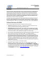
Overview .................................................................................................................. 33
Software Developers Kit (SDK)................................................................................. 33
ProductInfo Protocol Description .............................................................................. 34
Protocol Implementation Rules ................................................................................. 35
ScanVue5® Implementation Rules ............................................................................ 36
ScanVue5® Supported Modes .................................................................................. 37
Fixed Unit Identification............................................................................................................... 37
User Configurable Unit identification........................................................................................... 37
Setup for Windows Networking (SMB) ....................................................................................... 37
®
ScanVue5 FTP server configuration......................................................................................... 37
Setup for FTP, QFX, NTP, PRODUCTINFO .............................................................................. 38
Product Query configuration....................................................................................................... 38
Presentation configuration .......................................................................................................... 39
Miscellaneous configuration ....................................................................................................... 41
Command modes....................................................................................................................... 43
Programmatic Modes ................................................................................................................. 44
QFX Quick File Transfer Protocol ............................................................................. 45
Using Graphics Characters....................................................................................... 46
Using Input Devices.................................................................................................. 47
Touch Screen ............................................................................................................................. 47
Keypad ....................................................................................................................................... 48
Push Buttons .............................................................................................................................. 48
Magnetic Stripe Reader.............................................................................................................. 49
Configuring,Scanvue5 for Input Devices ................................................................... 49
Enable Multiplexer ...................................................................................................................... 49
Start Event and End Event Masks.............................................................................................. 49
Push Buttons .............................................................................................................................. 49
Touch Screen ............................................................................................................................. 49
Keypad ....................................................................................................................................... 50
Data Bytes (Parameters) ............................................................................................................ 50
Structure of EVENT packet....................................................................................... 50
Examples (shown in hex form) ................................................................................................... 52
ScanVue420 Vacuum Fluorescent Display ............................................................... 53
Description ............................................................................................................... 53
Operation.................................................................................................................. 53
Text Slideshow ........................................................................................................................... 54
Changing Language Character Sets......................................................................... 54
Customer Messages................................................................................................. 55
Changing Messages................................................................................................................... 55
Appendix A—Configuring with Barcodes ............................................................................ 56
Barcode Reader Settings.......................................................................................... 56
23-June-2008
vii
®
ScanVue5 Mini Kiosk
User Manual
M37574–01T
Industrial Electronic Engineers, Inc.
Recommended Scanner Settings ............................................................................. 56
Configuring ScanVue5® ............................................................................................ 56
Appendix B—ScanVue5® Initialization File......................................................................... 61
Overview .................................................................................................................. 61
Real Time Clock ....................................................................................................... 61
Rules for the ScanVue.ini File................................................................................... 62
Sections & Commands ............................................................................................. 63
Example of Initialization File ..................................................................................... 65
Appendix C—Creating a Slideshow.................................................................................... 67
Creating a Slideshow File ......................................................................................... 67
Using Multiple Graphics Windows............................................................................. 67
Sections & Commands ............................................................................................. 68
Examples of Slideshows........................................................................................... 69
Appendix D—Font and Language Sets............................................................................... 72
Graphics (TFT) Display Models ................................................................................ 72
Vacuum Fluorescent (VF) Display Models ................................................................ 73
Appendix E—ProductInfo Protocol ..................................................................................... 76
Appendix F—Mounting Bracket Outlines ............................................................................ 83
Appendix G—Application Notes ......................................................................................... 85
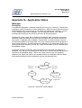
Wallpaper ................................................................................................................. 85
Description.................................................................................................................................. 85
Creating Wallpaper..................................................................................................................... 86
Using Wallpaper ......................................................................................................................... 86
Text Over Graphics (Mixed Mode) Operation............................................................ 88
Network Messages ................................................................................................... 89
Greeting Message .................................................................................................... 91
Appendix H—Expanded Text API....................................................................................... 92
API Notation ............................................................................................................. 92
Defining a Text Box .................................................................................................. 92
Text Color................................................................................................................. 93
Writing to a Text Box ................................................................................................ 94
Text Timeout ............................................................................................................ 94
Appendix J—IEE FTP Site ................................................................................................. 95
Appendix K—Running an Open Socket .............................................................................. 95
Appendix L—Network Diagnostics...................................................................................... 96
Diagnostic Configurations........................................................................................................... 96
Diagnostic Screens and Messages ............................................................................................ 97
23-June-2008
viii
®
ScanVue5 Mini Kiosk
User Manual
M37574–01T
Industrial Electronic Engineers, Inc.
TABLE OF FIGURES
Fig 1—Wall Mount Bracket..............................................................................................7
Fig 2—Optional Stand Mounted ......................................................................................8
Figure 6—Connector Location—Rear of ScanVue5 ......................................................10
Table 1—Cobra Scanner Setup Codes .........................................................................12
Figure 7—Wiring Cobra Hand Scanner .........................................................................13
Figure 8—Wiring a Serial Printer ...................................................................................16
Figure 9—Configuration Status Screen 1 ......................................................................21
Figure 10—Configuration Status Screen 2 ....................................................................21
Figure 11—Unit Configuration (UnitConfig) Screen .......................................................23
Figure 12A—Unit Configuration V6.20 AMLCD .............................................................26
Figure 12B—Unit Configuration V6.20 VFD ..................................................................28
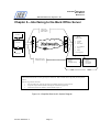
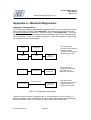
Figure 14—Simplified ScanVue5® System Diagram ......................................................32
Figure 15—Greeting Screen..........................................................................................53
Figure 16—Item Description & Price Display.................................................................54
Table 2—Barcode Configuration Labels ........................................................................59
Figure 17–Real Time Clock Display ..............................................................................62
Figure 18—Timing Chart for Multiple Window Example.................................................71
Figure 19—Multiple Graphics Windows.........................................................................71
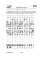
Table 3—Default ASCII Character Set For TFT Display ................................................72
Table 4—Default ASCII Character Set for VF Display ...................................................73
Table 5—European Character Set for VF Display .........................................................74
Table 6—Katakana Character Set for VF Display..........................................................74
Table 7—Cyrillic Character Set for VF Display ..............................................................75
Table 8—Hebrew Character Set for VF Display ............................................................75
Figure 24—Slimline Wall Mount Bracket .......................................................................83
Figure 25—Co-Located Printer Wall Mount Bracket ......................................................84
Figure 26—ScanVue5® State Diagram..........................................................................85
Figure 27—Wallpaper Image.........................................................................................86
Figure 28—Text Over Wallpaper ...................................................................................87
Figure 29—UnitConfig Screen, msgChecking Mode......................................................90
Figure 30—Default English Greeting Message..............................................................91
Figure 31—Spanish Greeting Message.........................................................................91
Figure 13—Diagnostic Configurations ...........................................................................96
Change history ............................................................................................................100
23-June-2008
ix
®
ScanVue5 Mini Kiosk
User Manual
M37574–01T
Industrial Electronic Engineers, Inc.
Chapter 1—Introduction
What’s in this Manual
This manual provides instructions for installation and operation of the IEE ScanVue5®
Price Verifier. Chapter 1 introduces the ScanVue5® hardware and describes its basic
functions and features. The following chapters describe how to physically install the unit
in its intended location, configure and set up your specific network and interface
ScanVue5® to a back office server through its Application Programming Interface (API).
The current software version number is displayed on the first status screen appearing
after powering up the unit (if properly configured). A barcode is available to display the
status screen directly (Appendix A); the host can query the unit for the same information.
Software updates, the entire CD-ROM SDK contents and later versions of this manual
are available on IEE’s FTP web server at www.ieeinc.com.
Be aware that ScanVue5 models running V5.x software cannot be upgraded to V6.x
software as the hardware platform is different. The same server application will work
with both software versions with the exception that some features supported in V6.x may
not be supported in V5.x.
Revision R of this manual is current with software version V6.20. Certain features may
not be supported in earlier software versions or hardware platforms. User Manuals
specific to software versions and hardware platforms can be obtained on request.
ScanVue® Models
The ScanVue® can be configured as a kiosk or as a price verifier. In its kiosk form it may
be sold with touchscreen, printer, keypad, magnetic stripe reader, barcode reader and
LCD display. Each input device is optional so that in its price verifier form it consists of a
number of different models that appear externally identical but have different features.
Model TA05–2XX is a hard–wired only unit with a ¼ VGA color AMLCD display. Models
TA05–1X and TA05–3X have an optional 11Mbps (IEEE 802.11b) wireless–network
interface installed, while Model TV42–XX has a 4x20 fixed width character vacuum
fluorescent (VF) display with optional wireless–network. Each of these models have an
optional bank of 4 switches on the front panel. These switches have no pre–assigned
functions but when depressed send the switch number and time–open and –close
events to the host computer. Models with a co-located Citizen printer (uses the same
power supply for the printer and ScanVue5 and shares a dual mounting bracket),
keypads and a magnetic stripe reader are available. AMLCD models also have a 16x12
digital touch screen available that operates in a similar way to the switches, sending the
X,Y co-ordinate of the location on the screen when touched.
All these models are transparent to the API—that is, they may be interchanged without
having to modify host computer software or your network. A sister product, ShopVue5®
which uses the same display in a slim housing without the scanner can also co–exist on
the same network. It operates from the same software and can be used in locations
where only the advertising is needed such as a checkout stand.
23-June-2008 Rev T
Page 1
®
ScanVue5 Mini Kiosk
User Manual
M37574–01T
Industrial Electronic Engineers, Inc.
ScanVue5® Description
ScanVue5® is a multi–function price verifier designed to allow a retail store customer to
check the price of any UPC barcoded product without having to leave the aisle or shelf
area. As well as displaying the price and description of scanned items, ScanVue5® color
graphics LCD can display specials or promotions, manufacturers co-op advertising,
check gift card balances or provide other customer information. Thus, as well as
performing a service to the customer, ScanVue5® can directly generate advertising
revenue for the store. The advertising display can be sequential still images (slides),
short animation clips, text, graphics or a mix of all these types of display. The
contemporary housing design merges well with almost any store décor and custom color
combinations are available if the units are ordered in sufficient quantities. A number of
different options for mounting the ScanVue5® unit are available.
The ScanVue5® price verifier consists of a barcode scanner located in the underside of
the housing, a 5.7”, ¼ VGA color graphics LCD display or [optional] 4x20 vacuum
fluorescent display, 4 [optional] front panel push button switches that can be used to
perform any function required by the end user, and an embedded microprocessor–based
controller running an application program that drives the scanner, the push buttons and
the graphics display and manages the operation of the unit. Communications between
ScanVue5® and the host computer can be hardwired 10baseT Ethernet or wireless
802.11x. An external RS232 serial port is available via an optional Y cable and supports
a hand scanner a coupon printer or any other serial device. The electronics package is
completely contained in a high impact ABS injection molded case. A metal mounting
bracket is shipped with the unit. The unit meets most worldwide regulatory safety and
EMC standards including UL1950, CSA22.2, TUV, FCC, CDRH, NOM and CE.
A new feature of ScanVue5’s software is the ability to run a “protocol converter”. This
means that an existing price-verifier application running on a network server for another
type of unit can be converted at the ScanVue5 side to run without a rewrite of the host
application code. Contact factory for quote for a custom protocol converter.
Demonstration Mode
Demo mode provides a functional demonstration of Scanvue in a ‘stand alone’ mode
without the need to connect to a network. In demo mode, an internal server and item
lookup file will display graphic item information when the appropriate item barcode is
scanned. The demo program uses multiple level images to show how additional item
information can be displayed—for instance, a food item can display a recipe on the
second level.
Demo mode is entered by scanning Demo Mode and then the Save and Reset
barcodes. The unit will stay in this mode until barcoded back to its normal mode. Demo
item barcodes are available in the documentation section of the CD-ROM.
Technical Knowledge Required
Installation
The installation of ScanVue5® is a reasonably easy process for a person familiar with
installing and maintaining local area networks (LAN’s). Although we have provided
various software tools to help with the network setup, this manual is not intended to be a
23-June-2008 Rev T
Page 2
®
ScanVue5 Mini Kiosk
User Manual
M37574–01T
Industrial Electronic Engineers, Inc.
training guide for novice network installers. It is assumed the installation will be done by
a person having a sufficient level of technical expertise with LAN hardware and software
to understand the content of this manual and complete the job with minimal outside help.
A system or network administrator is capable of performing the installation with ease.
IEE can provide additional technical assistance in getting the system running, if required.
Operation
Once ScanVue5® units are installed and configured, any person familiar with a PC and
able to write simple macros or script files will be able to create graphics–based
presentations (called slideshows) using Microsoft WordPad™ or a similar text editor.
Image files can be obtained from various sources—downloaded from a website,
scanned in from a digital scanner or transferred from a digital camera. Familiarity with a
graphics editor program would be helpful in preparing the images for slideshow
presentations.
Application Program Interface (API)
An API that provides the interface between ScanVue5® and the network host computer
application is described in detail in Chapter 4. The API is written in ANSI “C” and can be
integrated with any ANSI ‘C’ compiler. The database application and its interface to
ScanVue5® will generally reside on the network host computer (sometimes called the
network server). Numerous different hardware or software platforms may be used as
long as TCP/IP is the network transport–protocol. Typical platforms are AS400, VAX,
Wintel hardware running Windows NT/2000/ME/XP, Unix, VMS, Oracle, SQL…
The database application program is responsible for receiving a request from a scanner,
retrieving the price and description from the database, and returning that data to the unit
that initiated the request. The development and maintenance of any host computer
based application program required to access a product–information database is the
sole responsibility of the end user or their system integrator. IEE provides an SDK
including some license free “C” source code to assist the end user in writing applications
on their host machine.
23-June-2008 Rev T
Page 3
®
ScanVue5 Mini Kiosk
User Manual
M37574–01T
Industrial Electronic Engineers, Inc.
23-June-2008 Rev T
Page 4
®
ScanVue5 Mini Kiosk
User Manual
M37574–01T
Industrial Electronic Engineers, Inc.
Technical Assistance
If you require technical assistance in bringing up your ScanVue5® Price Verifier, please
call (818) 787–0311 and ask for Technical Support. Please be prepared to discuss your
configuration and setup parameters.
23-June-2008 Rev T
Page 5
®
ScanVue5 Mini Kiosk
User Manual
M37574–01T
Industrial Electronic Engineers, Inc.
Chapter 2—Installing ScanVue5®
Items Shipped with ScanVue5®
ScanVue5® with barcode scanner and display. Model options include:
¼ VGA TFT display
VFD 4x20 display
¼ VGA Blue/White display (only available with Ethernet and linear scanner)
Ethernet 10BaseT or Ethernet+802.11b Wi-Fi.
Co-located Citizen label printer
20 Key keypad
Magnetic stripe reader
16 x 20 digital touch screen
Omni-directional or linear scanner
A 16VDC/30W AC desktop ‘brick’ with a standard 8 pin DIN female connector. The input
is universal 90-264VAC/50-60Hz and the power supply has global certifications.
SDK (software developers kit) includes programs for setting up the ScanVue5® unit and
the server, API code, demo programs, font files, user manuals in PDF format, and thirdparty useful utilities.
Mounting brackets are provided.
A desktop stand kit is available as an option (P/N 38572-02)
The following accessories are available.
Stand mount kit (IEE P/N xxxxx-02)
6' DC power extender cable with DINF to DINM connectors (IEE P/N 37082–72).
Y cable for Symbol Cobra or NCR 7837 hand scanner (IEE P/N 37915-XX).
Y cable for NCR 7137 Thermal Printer (IEE P/N 38094-XX).
Y cable for NCR K590 Self Service Printer (IEE P/N 38254-XX)
Y cable, RS232 Universal with DB9F connector (IEE P/N 38516-07)
Mounting the ScanVue5® Unit
There are two (2) ways the ScanVue5® Price Verifier can be mounted.
1. Wall mounted from the back of the unit.
2. Stand mounted for desk or counter top installation
23-June-2008 Rev T
Page 6
®
ScanVue5 Mini Kiosk
User Manual
M37574–01T
Industrial Electronic Engineers, Inc.
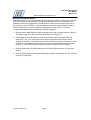
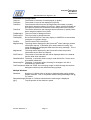
Wall Mounted
The wall mount bracket is provided as a standard item shipped with the unit (Appendix F
for actual dimensions). The wall bracket can be mounted on any type of flat vertical
surface using the 6 mounting bosses with holes. The bracket can also be mounted by a
special double-sided tape to a glass column or wall. Mounting hardware is not provided
as the material used in the vertical wall can vary depending on the location chosen and
either wood screws or toggle bolts or equivalent are recommended. Do not use wood
screws or sheet metal screws in drywall—they will not hold the weight of the unit.
Note: contact factory for recommendation of double sided tape—do not use the kind you might find
in the local drug store or hardware store.
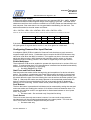
The wall mount bracket is removed from the rear of the unit, sliding it up and off of the 4
vertical tongues, and mounted to the wall, column or endcap. A hole is provided in the
bracket for bringing the power and/or network connection through from the wall or
column.
Locking screws (x2)
Fig 1—Wall Mount Bracket
The ScanVue5 unit is pushed close to the wall about 1” above the bracket tongues.
Push it downward until the 4 tongues mate securely with their counterpart slots in the
rear of the housing. Tighten the 2 locking screws through the slots in the housing until
snug—this will prevent anybody from removing the unit from its mount.
23-June-2008 Rev T
Page 7
®
ScanVue5 Mini Kiosk
User Manual
M37574–01T
Industrial Electronic Engineers, Inc.
A double-wide bracket that places the label printer directly on the left side of Scanvue is
provided when the co-located printer option is purchased. The printer and Scanvue are
mounted side by side on a sub-panel pre-wired for a single power supply and ready to
be mounted to a wall almost exactly like a single Scanvue.
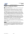
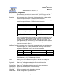
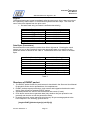
Stand Mount
An optional kit can be purchased (IEE P/N xxxxx-01) for mounting the unit on a desktop
or counter top. The stand comes with assembly instructions and a special VESA mount
bracket to replace the wall mount bracket. Once mounted on the stand the unit can be
swiveled left and right, up and down and raised or lowered to get the best possible
position for the scanner.
Fig 2—Optional Stand Mounted
23-June-2008 Rev T
Page 8
®
ScanVue5 Mini Kiosk
User Manual
M37574–01T
Industrial Electronic Engineers, Inc.
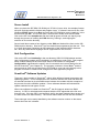
Wiring the Ethernet Model
Once the ScanVue5® unit is mounted in place there are 2 cables (1 cable only if 802.3af
IEEE PoE option is selected) that must be connected before it can be operated. For
aesthetic reasons we suggest the AC and network outlets are mounted close to (or in)
the ceiling or close to the floor. The two cables may also be routed inside the wall or
column and plug into the AC and network connections in the ceiling. This is the
recommended method and provides the cleanest installation.
1. Plug the RJ45 cable Ethernet cable connected to the hub or switch on your LAN into
the RJ45 connector in the rear of the ScanVue5® unit (Figure 6).
2. Connect the 8–pin DIN extension cord and the DIN connector coming from the
ScanVue5® unit. Line up the arrows on the two connectors and the pins will be
aligned for insertion. On some models, the 8–pin DIN connector is mounted on a PC
board that is accessible from the back of the unit underneath the mounting bracket
(Figure 6). The RJ45 Ethernet connector is also mounted on this PC board
3. Plug the other end of the DIN extension cord into the DIN connector on the power
supply.
4. Plug the power supply into a grounded electrical outlet—the ScanVue5® unit will start
its boot–up sequence.
23-June-2008 Rev T
Page 9
®
ScanVue5 Mini Kiosk
User Manual
M37574–01T
Industrial Electronic Engineers, Inc.
Figure 6—Connector Location—Rear of ScanVue5
Wiring the RF Wireless Model
If you purchased the wireless network option, the 802.11b Wi-Fi card will already be
installed and tested at the factory. The installation is the same as shown above for a
hardwired unit, except no RJ45 cable is needed for wireless operation.
Installation of RF communication links requires special expertise and is part of your site
network and as such the manufacturer of the access point (and your network staff)
should be the first line of technical support. Most of the manufacturers of access points
have extensive technical documentation on performing RF site surveys and correct
installation of the units on their web sites.
Entering the ESSID
Each wireless RF access point has a network name (called an ESSID) that consists of
up to 32 letters and numbers. When a new ScanVue5® is shipped from the factory, a
default ESSID (INSTALL) is stored in configuration memory. Before it will communicate
23-June-2008 Rev T
Page 10
®
ScanVue5 Mini Kiosk
User Manual
M37574–01T
Industrial Electronic Engineers, Inc.
with the access point, the ScanVue5® must have a matching, case sensitive ESSID
entered into its memory to replace the default. The ESSID can be entered through the
ScanVue5® internal barcode reader.
The ESS ID is a barcode label in the following format:
NN nn x1…x32
where NN=fixed characters, nn=# of characters in ID (1–32)
x1…x32 = ID (1–32 characters)
Load the ESS ID as follows:
1. Create a barcode label with the ESS ID formatted as described above.
2. Power the ScanVue5® unit and verify the barcode scanner is operational—look at the
underside and check the scanner is lit and rotating.
3. Scan the ESS ID barcode you created.
4. Scan the “Save Configuration and Reboot” barcode.
5. The ScanVue5® unit will reboot and should now communicate with the network.
Setting Up a Wireless RF Link
Before installing a new wireless RF data link, it is important to perform an RF site survey
to characterize the immediate environment and ensure a reliable system is designed.
The general pointers we indicate below will assist in the initial installation and diagnosis
of a link problem, however your first line of technical support is the specialized help
available from the manufacturer of the access point or your IS or VAR people doing the
installation.
1. Unobstructed line–of–sight is best. If you can, arrange the ScanVue5® units so there
is an unobstructed line–of–sight to the access point. Under these ideal conditions
and assuming no interference from other 2.4Ghz sources, you should get up to 150'
distance. In a typical office or retail environment 30'–50' is more typical.
2. Mount the access point as high as possible in the line–of–sight. This way the signals
should travel above racks, shelving, customers, etc. The human body is 90% water
and a good RF signal absorber—this is why cell phones often don’t work well inside
buildings and around crowds of other people.
3. Keep reflective surfaces like mirrors and polished stainless steel, and metal objects
with sharp points to a minimum and away from the antenna as much as possible.
4. If you are having trouble making a connection, try moving the ScanVue5® closer to
the access point, raising it, or lowering it.
As the ScanVue5® unit cannot easily be moved once installed, it is often more
convenient to have a portable signal strength meter or an IEEE802.11b RF NIC card
in a laptop computer during installs. The NIC driver will have a RSSI graph or will
display the signal strength as a percentage depending on the NIC used.
23-June-2008 Rev T
Page 11
®
ScanVue5 Mini Kiosk
User Manual
M37574–01T
Industrial Electronic Engineers, Inc.
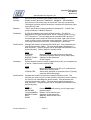
Adding a Hand Scanner
If your ScanVue5® has software version 4.12 or later, a hand scanner on a cable may be
installed in addition to the fixed scanner. The hand scanner is useful for departments
that sell large items that cannot easily be read by the fixed scanner. ScanVue5® works
with either scanner transparently—that is, either the fixed scanner or the hand scanner
can be used to read an item barcode without having to select which one is being used.
Two manufacturers hand scanners are supported. The Symbol Cobra 1902T scanner
requires an optional ScanVue5® power supply Y cable (IEE P/N 37915–XX, where XX
specifies the cable length) that provides the additional RS232 port, serial port 2, for the
hand scanner to connect to the ScanVue5® unit. The Cobra scanner comes with its own
wall mount power supply to power the scanner and is required in addition to the power
supply that powers the ScanVue5® unit. The RS232 port is factory pre-set to run the
hand scanner. The NCR model 7837 construction and cabling is almost identical to the
Cobra and supported in the same way. The following paragraphs describe setting up
the Cobra scanner in detail. A similar setup is required for the NCR scanner.
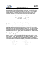
Wiring and Configuring the Hand Scanner
Once the Cobra scanner is powered up, it must be configured to communicate with
ScanVue5®. Section 4 of the Cobra manual contains the barcodes required to perform
the setup needed. A manual can be obtained from the Symbol website
www.symbol.com if you don’t have one. Scan the following barcodes in the order
shown in Table 1.
Barcode
Set all defaults
Standard RS232C
RTS/CTS option 2
Scan Suffix
1
0
1
3
Scan Options
<DATA><SUFFIX>
Enter
Cobra Manual Page #
4–10
4–23
4–30
4–116
4–119
4–119
4–119
4–119
4–117
4–117
4–118
Note
Default: 7–bit, odd parity
Numeric bar code
Numeric bar code
Numeric bar code
Numeric bar code
Table 1—Cobra Scanner Setup Codes
Y Cable
Part No. 37915
Power supply
provided with
ScanVue5
23-June-2008 Rev T
Page 12
®
ScanVue5 Mini Kiosk
User Manual
M37574–01T
Industrial Electronic Engineers, Inc.
RS232
connector
Symbol Cobra
Scanner
Cobra Scanner
Power Supply
Power supply and
RS232 cables provided
with Cobra scanner
Figure 7—Wiring Cobra Hand Scanner
23-June-2008 Rev T
Page 13
®
ScanVue5 Mini Kiosk
User Manual
M37574–01T
Industrial Electronic Engineers, Inc.
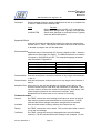
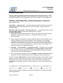
Adding a Serial Printer
Software versions 4.16 and later provide support for an external serial printer as well as
a hand scanner. The factory default setting for serial port 2 is SCANNER for hand
scanner use. If a serial printer is required instead of the scanner, serial port 2 must be
changed to OUTPUT or BIDIRECTIONAL using UnitConfig or the modeset commands.
The port may also be disabled by setting it to NONE.
In OUTPUT mode the port parameters are pre-configured for the NCR model 7197
Thermal Receipt Printer. You must also purchase a special Y cable (IEE P/N 38094–XX,
where XX specifies the cable length) which breaks out the RS232 port for the printer
from the DIN power connector on the rear of Scanvue.
In BIDIRECTIONAL mode the port parameters are pre-configured for the NCR model
K590 Self Service Printer. A Y cable (IEE P/N 38254–XX) is required to connect this
printer to ScanVue5®. The K590 printer has built-in sensors and diagnostics to detect
error conditions that can be reported back to the server through this port.
Other manufacturers serial printers may require a different Y cable or port settings.
Check with the factory before attempting to connect a different printer.
In OUTPUT or BIDIRECTIONAL mode, serial port 2 is a transparent RS232 data port.
ScanVue5® receives pre-formatted data and control codes from a printer driver resident
on the network host, which it passes, unmodified, through serial port 2 to the printer.
Any data returned from the K590 printer in BIDIRECTIONAL mode will be passed up to
the network host unmodified. Printer drivers are specific to the printer used and must be
provided by the user.
Wiring and Configuring the Serial Port
Use the UnitConfig program or modeset utility to change the serial port configuration to
OUTPUT or BIDIRECTIONAL. If you are using an MS Windows system, open a DOS
box and change to the C:\POS directory where modeset is stored and send the 2
following lines. The modeset utility, found on the CD-ROM, must be copied onto your
server before these commands can be sent.
C:\POS modeset -iPort2function=OUTPUT {BIDIRECTIONAL} <IP>
C:\POS modeset -c -r <IP>
where <IP> is the unit’s IP address.
The default serial port 2 settings for OUTPUT are 9600 baud, no parity, 8 data bits, 1
stop bit for and for BIDIRECTIONAL are 19200baud, no parity, 8 data bits, 1 stop bit.
The printer port settings must be set to the same parameters to be able to communicate
with it. If you want to run the printer faster or change other parameters, a utility program
PortSet is provided on the CD-ROM for modifying serial port settings.
23-June-2008 Rev T
Page 14
®
ScanVue5 Mini Kiosk
User Manual
M37574–01T
Industrial Electronic Engineers, Inc.
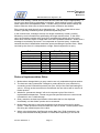
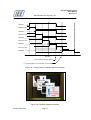
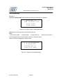
Sending Data to the Printer
The host server must use nominal-mode ProductInfo packets to send data to the printer
(see Chapter 5). The packets required are Data type, Special Text sub-type. An
example of a typical message is:
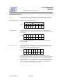
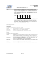
Byte Count
0-3
4-7
8-11
12-18
23-June-2008 Rev T
Value (Oh)
00 00 00 13
44 41 54 41
53 50 45 43
48 65 6C 6C 6F 21 0A
Page 15
Meaning
Length of packet (19 bytes)
‘DATA’ Data type
‘SPEC’ Special Text sub-type
‘Hello!<LF>’ Text sent to printer
®
ScanVue5 Mini Kiosk
User Manual
M37574–01T
Industrial Electronic Engineers, Inc.
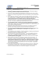
Y Cable
Part No. 38094
or 38254
Power supply
provided with
ScanVue5
DB9 female
connector
Serial
Printer
Figure 8—Wiring a Serial Printer
Connecting To the USB Port
A Type I, USB 1.0 port is available on the rear panel. The USB port does not provide
power to the load device. Any standard USB cable will connect this port to a device
such as a printer. The LX800 has three sockets, the one closest to the motherboard is
NOT connected electrically; it is there for spacing only.
The USB port is currently used to connect an external Magnetic Stripe Reader (MSR).
See the section under Port3Configuration for more details.
Wiring Precautions
While ScanVue5® is designed to withstand power and data line surges, spikes and other
anomalies in accordance with IEC and CE specifications, it will probably not survive a
direct lightning strike. In parts of the USA and worldwide where there is a high likelihood
of thunderstorm activity it is good practice to install lightning surge protectors on all
power and data lines. ScanVue5® should be treated like any other network and
computer product installed in your facility.
23-June-2008 Rev T
Page 16
®
ScanVue5 Mini Kiosk
User Manual
M37574–01T
Industrial Electronic Engineers, Inc.
Chapter 3—Installing the Software
Note: it may be easier to follow the step by step Quickstart Guide (available on the CD
ROM in the documentation section).
Before installing the Scanvue5 programs, we highly recommend you install the latest
updates or service packs to the operating system you are using. The UnitConfig
program especially requires a minimum level of Internet Explorer to be running. On
Windows 98, IE Explorer 6.0 or later and NT or XP require IE Explorer 5.50 or later.
The SetupServer program on the CD–ROM must be run on your Windows network
server to create a specific ScanVue5® directory called POS on your servers’ hard disk,
share it and copy the default scanvue.ini file into this directory. ScanVue5® units look
for this file in the POS share when they boot up and will not operate if they can’t find it.
In software versions after and including V5.02, the .ini file will be searched for in all lower
case characters. This takes care of servers that are case sensitive (such as Unix)
You should also install UnitConfig the graphical, table oriented version of modeset on
the server as it provides the easiest way to change the configuration of a unit on the
network (as opposed to scanning barcodes or sending modeset commands). You may
also install UnitConfig on a desktop or laptop computer for setting up ScanVue5® units
without a large network complicating it. You will need a network interface card (NIC)
installed in your PC and configured properly to communicate with ScanVue5®.
UnitConfig version 3.3 or later can also be run directly from the CD-ROM.
For servers that are running other than Windows, sources are provided for the server
software. There are also freely available drivers to allow any operating system to act as
a Windows–type server.
Important: Scanvue5 V6.2 and later software will detect either scanvue.ini or
realscan.ini files. This ensures that an existing NCR installation using realscan.ini will
work with new Scanvue units. The shared ScanVue directory and the file must be on the
server and the ScanVue5® unit must be able to find it when they power up. If you want
to change the operating modes (or configuration) of a specific unit anytime after the
system is up and running, the UnitConfig program is available in the POS directory or
on the CD-ROM.
23-June-2008 Rev T
Page 17
®
ScanVue5 Mini Kiosk
User Manual
M37574–01T
Industrial Electronic Engineers, Inc.
Server Install
When you place the IEE SDK CD–ROM (p/n 37720-01) into a drive, the autoplay feature
will open a window with the folders and program icons. If it doesn’t start on its own, click
Windows START button, then Run and enter the CD-ROM drive name (usually d:) in the
text box and click OK. The CD will open a new window–double click the IEE folder.
Click on the IEE icon SetupServer and the install program will lead you step by step
through the process of creating the POS directory, sharing it, and copying the
scanvue.ini file into the directory.
Server install also creates a font directory under POS and loads all the fonts on the CD–
ROM into this directory. ScanVue5® has one default font programmed into the unit. This
is a 16x32 pixel glyph containing all 256 characters of the extended ASCII character
set—thus any Latin based language can be supported from this font set.
Unit Configuration
Click on the IEE icon UnitConfig in the root directory SDK CD–ROM window and the
Unit Configuration program will be installed in a subdirectory under POS. This program,
which consists entirely of the one screen shown in the section on using Unit
Configuration, implements the specific set of commands and controls defined in the
API for ScanVue5® (see Chapter 5). The program is written in Visual Basic® and the
sources and an OCX are provided on the CD–ROM so users can write directly to this
program and make or initiate mode changes from their application program
ScanVue5® Software Updates
There are 2 basic models of ScanVue5®, which utilize different internal processors and
operating systems. This is transparent to the customer and the API user and there are
no external functional or physical differences between the models with the exception of
the process for online software updates. Future software releases will include both
update methods for both types of units.
When new software is loaded into ScanVue5®, the file image is written into RAM
memory. A CRC is calculated and compared with the CRC appended to the file sent
from the host. If the two CRC’s are identical, the file has been loaded without errors and
it is then written into flash memory. The unit will reboot itself and run the new software.
The model type can be easily identified by the software version number on the status
screen when the unit is booted.
23-June-2008 Rev T
Page 18
®
ScanVue5 Mini Kiosk
User Manual
M37574–01T
Industrial Electronic Engineers, Inc.
Chapter 4—Network Configuration
Introduction
ScanVue5® is a network–connected device which uses industry standard TCP/IP
protocols for communication. Connecting ScanVue5® to your network requires the same
kind of preparation as connecting a workstation to your network. This manual assumes
you know how to obtain the relevant information about your existing network
configuration and choose the appropriate configuration parameters so your network will
recognize ScanVue5® devices. We suggest using switches rather than hubs to connect
to ScanVue5® units as the bandwidth and response time is improved.
ScanVue5® supports two activities—displaying item price and description and displaying
a graphics slideshow. The unit has two primary modes of operation: an idle mode where
a slideshow from 2 to 50 sequential images is continuously displayed, and an interactive
mode where a customer scans an item and price and description information is returned
by the host server. The four buttons on the front panel can be configured to only be
active when in the interactive mode. In order to display product information, ScanVue5®
must connect to a host computer that has the product information stored in its database.
If you are using an MS Windows network, we highly recommend Windows NT, 2000,
ME, or XP. Windows 95 and 98 can be used as a server for ScanVue5®, but they are
not supported. NT 4 Server and Windows 2000 will provide the best performance in
terms of response speed, especially if you are using an RF wireless system rather than
hardwired Ethernet (10/100baseT).
Network Activity
ScanVue5® includes servers for FTP (port 21), ProductInfo (port 1283), and clients for
FTP, SMB (Windows networking), ProductInfo (Product Information Protocol) and QFX
(Quick File eXchange). FTP, SMB or QFX can be used to get the graphics files for
ScanVue5®’s slideshow. SMB is the default mode.
ScanVue5® ships from the factory with the following default network settings.
IP Address:
Unit ID:
User Name:
Windows Server:
Wireless
DHCP¹
Sub–Net Mask:
ScanVue5®
GUEST
Password:
SVSERVE
Windows Share:
TRUE (unencrypted)
¹Some hard–wired only models default to 10.0.0.227
23-June-2008 Rev T
Page 19
255.255.0.0
(none)
POS
®
ScanVue5 Mini Kiosk
User Manual
M37574–01T
Industrial Electronic Engineers, Inc.
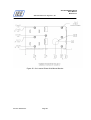
ScanVue5® requires a file server for storing graphics files and a ProductInfo server (host
or back office computer) for the price/description database. These servers may be (but
don’t have to be) on the same physical computer. The file server must have the
ScanVue5® initialization file (ScanVue.ini) in its POS shared directory (if SMB–based) or
the default directory for FTP or QFX, and may also have font, graphic, and slideshow
script files. The file server can be a Windows system, or an FTP or QFX server on any
type of hardware or OS provided it runs TCP/IP.
ScanVue5® sends the UPC number read from a barcoded item placed under the
scanner to the ‘ProductInfo’ server on the host computer which uses this number as a
key to find the item in the price and description database(s). After the item records are
retrieved, the host application prepares the response and sends it back to ScanVue5®
where the information is displayed. The response can be text only, graphics only or a
combination of text and graphics.
ScanVue5® Configuration
There are three ways to configure a ScanVue5® unit:
1. Using its internal barcode reader to scan special purpose barcodes.
2. Commands sent across the network using the UnitConfig or modeset programs
3. Following the procedure in the ‘Quickstart Guide’. Of course ScanVue5® must be
able to communicate with the server on the network before its configuration can
be changed on the network.
If you are using wireless RF units, you must enter the ESSID of the access point you
are communicating with via the barcode reader before the unit will associate with the
access point. Additionally, if your network uses WEP or WPA, ScanVue5® must be
setup to match the access point.
Quickstart
The CD–ROM contains the ‘Quickstart Guide for Scanvue5’ (P/N 37681–01). The guide
applies to all Scanvue5 models and describes how to simply configure your units to
match the network settings using a desktop PC and a crossover cable or a passive hub
(see page 4). This is the easiest way to bring up the first few units without the added
complications of a large network.
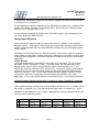
Configuration Information Screens
When ScanVue5® boots up, two configuration status screens (Fig. 9 and 10) are
sequentially displayed which show the current settings of the unit. Each screen is
displayed for 10 seconds then the unit will load the slideshow from the server and start
running. These screens can be displayed at any time by scanning the ‘show config
screen 1’ and ‘show config screen 2’ bar codes shown in Appendix A. In software
versions later than V4.15, wireless RF configurations display brown text on a light green
background and hardwired Ethernet units display yellow text on a blue background.
23-June-2008 Rev T
Page 20
®
ScanVue5 Mini Kiosk
User Manual
M37574–01T
Industrial Electronic Engineers, Inc.
Figure 9—Configuration Status Screen 1
Figure 10—Configuration Status Screen 2
Wireless Configuration Information
Three wireless radio link parameters are kept in the UnitConfig program. These
parameters are stored by the radio and give the end user a feel for the link quality and
the physical placement of the ScanVue5 unit. The 3 parameters are
Mode
Content
Link
Outrageous, excellent, good, fair, poor (quality of link in 1 of 5 categories)
Level
-256 dBM (signal level in dBM, lower number is better)
Noise
-136 dBM (noise level in dBM, higher number is better)
UnitConfig Program
Configuring ScanVue5® units over the network requires a GUI program called Unit
Configuration which is installed from the CD–ROM. Generally, configuration by special
barcode is kept for those occasions when a devices network configuration is incompatible
with the local network. Changes can be made off–line that will allow the unit to connect to
the network, just like the ‘Quickstart Guide”, but without needing the PC. Appendix B
23-June-2008 Rev T
Page 21
®
ScanVue5 Mini Kiosk
User Manual
M37574–01T
Industrial Electronic Engineers, Inc.
describes this method. Once the unit is network compatible the rest of the configuration
can be done through Unit Configuration.
Unit Configuration is a VisualBasic® program that provides a simple graphical way to
query and configure any ScanVue5® unit. It uses the ScanVue5® mode commands
(Chapter 5) to setup the unit. This program is available in both source and executable
form.
Modeset is a DOS command line program equivalent to UnitConfig that can query and
set modes through a text file or directly from the directory prompt.
Ex: modeset [mode value]
sets the mode to the specified value
modeset –g [mode]
returns the value of the mode
modeset
lists all non-hidden modes and their values
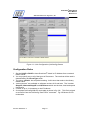
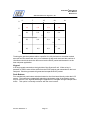
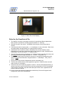
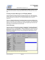
Using Unit Configuration
When the program is first started, all boxes in the screen are blank. Enter the IP
address of the ScanVue5® unit you wish to change in the Unit IP Address box. Click
the Read Modes button–all the Modes and their Content (values) will be read from the
subject unit and displayed as shown in Fig. 9.
To change a mode; highlight the New Content box in the same row as the mode you
want to change by clicking on it. Enter the new value in the box and click the Set Mode
button. If the value is accepted, the box and the button will turn green. If it is not
accepted, the box and button will turn red. Now click the Commit button, this will
commit the change to flash memory in the ScanVue5® unit. Multiple changes can be
made before committing them. If any of the changes are not accepted, the Set Mode
button will turn red and those changes marked in red were not made.
Clicking the Close button will blank the screen including the IP address box and allow a
new IP address, hence a new unit to be selected.
Clicking the TextReset button will apply changes made to text modes so they can be
seen immediately. As with other modes, the changes are not permanently stored until
the Commit button is clicked.
The SaveToFile button will save the setup to a text file where it can be stored and
printed if necessary. This is usually done for troubleshooting or maintaining hard copy
records of each unit’s configuration.
The Restart Unit button will cause a ‘soft boot’ of the selected unit.
Clicking on the Help button brings up a help screen that is a brief overview of how to use
the program. Additionally, the light color area at the bottom of the screen will display
context sensitive help for each mode as the mode is highlighted. For some modes, the
values available are indicated in this area. Other modes (for example Serial Number)
cannot be changed and will always turn the New Content box and Set Mode button red.
The Exit button closes the Unit Configuration program.
23-June-2008 Rev T
Page 22
®
ScanVue5 Mini Kiosk
User Manual
M37574–01T
Industrial Electronic Engineers, Inc.
Figure 11—Unit Configuration (UnitConfig) Screen
Configuration Rules
1. Set the UnitIP to DHCP to have ScanVue5® obtain its IP Address from a network
DHCP server.
2. You may specify any or all of the types of file servers. The one that will be used is
determined by the ServerType mode.
3. The value –default– has a special meaning: it will return that mode to the factory
default value.
4. “named servers” are available on software versions 6.10 and later. The 3 modes
SloppiIP, AlternateSloppiIP and QFXServer which are the host, host backup and
demoserve
5. a name of up to 12 characters or the IP Address.
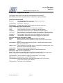
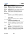
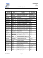
6. A complete UnitConfig AMLCD mode table is shown in fig 12A. This file is printed
as a text file from the UnitConfig “SaveToFile” command. Fig 12B shows a VFD
mode table.
23-June-2008 Rev T
Page 23
®
ScanVue5 Mini Kiosk
User Manual
M37574–01T
Industrial Electronic Engineers, Inc.
Mode
Content
Version
6.20x AMLCD
dateTime
20030303120301
buildInfo
20060726143227
productName
ScanVue
serialNumber
999999
unitID
ScanVue
unitIP
(via DHCP)
unitMask
255.255.0.0
gatewayIP
10.0.10.13
domain
(Not Set)
DNS
10.0.10.13
windowsServ
SVSERVE
shareName
POS
WINSserverIP
10.0.10.13
FTPServerIP
10.0.10.13
userName
GUEST
password
(Not Set)
SLOPPIHost
(Not Set)
AlternateSLOPPIHost
(Not Set)
sloppiport
1283
SLOPPITimeout 300
QFXHost
(Not Set)
QFXport
1284
QFXTimeout
300
KeepAliveTime 0
textRows
7
textCols
20
textHPos
0
textVPos
8
textForegnd
35
textBackgnd
180
TextDisplay
EXCLUSIVE
TextTransparent FALSE
Port2Function
Scanner
Port2Input
Line
POStimeout
30
PointerHScale
31
PointerVScale
23
RegisterINI
TRUE
RegisterStart
TRUE
SingleQTrans
FALSE
IgnoreAckNak
FALSE
IgnoreResponseChars 0
QueryPadTo
0
BypassNCRprefix TRUE
NoBarcodes
FALSE
QueryPrefix
(Not Set)
23-June-2008 Rev T
Page 24
®
ScanVue5 Mini Kiosk
User Manual
M37574–01T
Industrial Electronic Engineers, Inc.
ShowShortPoll
60
ShowLongPoll
300
TrivialComm
TRUE
sendUnitID
TRUE
sendError
FALSE
sendResponse FALSE
NTPhost
10.0.10.13
NTPTZoffset
480
eventStart
00000000
eventEnd
00000000
user1
(Not Set)
msgChecking
" Checking...
One moment please "
msgUnavail
" Unavailable
Please try later "
DisplaySetup
5
DisplaySetup2
5
DisplayAll
FALSE
ShowLogo
TRUE
WallPaperEvent 00000000
NetworkName
INSTALL
Diversity
PRIMARY
Wireless
TRUE
WEPEncryption None
WEPKey1
(Not Set)
WEPKey2
(Not Set)
WEPKey3
(Not Set)
WEPKey4
(Not Set)
WEPKeyIndex
1
BasePrefix
(Not Set)
HomeURL
(Not Set)
URLPrefix
(Not Set)
URLSuffix
(Not Set)
vPrefix
(Not Set)
vSuffix
(Not Set)
btPrefix
(Not Set)
btSuffix
(Not Set)
ScreenBlank
0
BDelay
0
MacAddr
00:e0:98:f5:84:6f
Link
100
Level
228
Noise
0
msrPrefix
(Not Set)
msrSuffix
(Not Set)
PLUFile
SSHPassword
********
AllowSSH
TRUE
DebounceKeypad TRUE
ProductCode
38196-01-620x
LocalHost
FALSE
Port3Function
(unknown)
23-June-2008 Rev T
Page 25
®
ScanVue5 Mini Kiosk
User Manual
M37574–01T
Industrial Electronic Engineers, Inc.
Port3Input
Character
UseWPA
FALSE
wpaScanSsid
TRUE
wpaKeyMgmnt
None
wpaPairwise
None
wpaGroup
None
wpaEAP
None
wpaPSKPassphrase
(Not Set)
wpaIdentity
(Not Set)
wpaPassword
********
wpaCACert
(Not Set)
wpaClientCert
(Not Set)
wpaPrivateKey (Not Set)
wpaPrivateKeyPasswd ********
wpaPhase1
(Not Set)
wpaPhase2
(Not Set)
wpaProto
(unknown)
wpaCACert2
(Not Set)
wpaClientCert2 (Not Set)
wpaPrivateKey2 Not Set)
wpaPrivateKey2Passwd ********
ServerType
SMB
Figure 12A—Unit Configuration V6.20 AMLCD
Mode
Content
Version
6.20x VFD
dateTime
20030305114715
buildInfo
20060724035241
productName
ScanVue
serialNumber
999999
unitID
ScanVue
unitIP
(via DHCP)
unitMask
255.255.0.0
gatewayIP
10.0.10.13
domain
(Not Set)
DNS
10.0.10.13
windowsServ
SVSERVE
shareName
POS
WINSserverIP
10.0.10.13
FTPServerIP
10.0.10.13
userName
GUEST
password
(Not Set)
SLOPPIHost
(Not Set)
AlternateSLOPPIHost
(Not Set)
sloppiport
1283
23-June-2008 Rev T
Page 26
®
ScanVue5 Mini Kiosk
User Manual
M37574–01T
Industrial Electronic Engineers, Inc.
SLOPPITimeout 300
QFXHost
(Not Set)
QFXport
1284
QFXTimeout
300
KeepAliveTime
0
ExtCharacterSet
EUROPEAN
Port2Function
Scanner
Port2Input
Line
POStimeout
30
RegisterINI
TRUE
RegisterStart
TRUE
SingleQTrans
FALSE
IgnoreAckNak
FALSE
IgnoreResponseChars 0
QueryPadTo
0
BypassNCRprefix
TRUE
NoBarcodes
FALSE
QueryPrefix
(Not Set)
ShowShortPoll
60
ShowLongPoll
300
TrivialComm
TRUE
sendUnitID
TRUE
sendError
FALSE
sendResponse
FALSE
NTPhost
10.0.10.13
NTPTZoffset
480
eventStart
00000000
eventEnd
00000000
user1
(Not Set)
msgChecking
" Checking...
msgUnavail
" Unavailable
DisplaySetup
5
DisplaySetup2
5
DisplayAll
FALSE
ShowLogo
TRUE
NetworkName
INSTALL
Diversity
PRIMARY
Wireless
FALSE
WEPEncryption
None
WEPKey1
(Not Set)
WEPKey2
(Not Set)
WEPKey3
(Not Set)
WEPKey4
(Not Set)
WEPKeyIndex
1
BasePrefix
(Not Set)
HomeURL
(Not Set)
URLPrefix
(Not Set)
URLSuffix
(Not Set)
vPrefix
(Not Set)
vSuffix
(Not Set)
23-June-2008 Rev T
One moment please "
Please try later "
Page 27
®
ScanVue5 Mini Kiosk
User Manual
M37574–01T
Industrial Electronic Engineers, Inc.
btPrefix
(Not Set)
btSuffix
(Not Set)
BannerText
" SELF SERVICE\x0A PRICE VERIFIER\x0AScan your
item belowfor price/sale info!"
ScreenBlank
0
BDelay
0
MacAddr
00:60:b3:79:2d:c6
Link
Level
Noise
msrPrefix
(Not Set)
msrSuffix
(Not Set)
PLUFile
SSHPassword
********
AllowSSH
TRUE
DebounceKeypad
TRUE
ProductCode
38196-02-620x
LocalHost
FALSE
Port3Function
(unknown)
Port3Input
Character
UseWPA
FALSE
wpaScanSsid
TRUE
wpaKeyMgmnt
None
wpaPairwise
None
wpaGroup
None
wpaEAP
None
wpaPSKPassphrase
(Not Set)
wpaIdentity
(Not Set)
wpaPassword
********
wpaCACert
(Not Set)
wpaClientCert
(Not Set)
wpaPrivateKey
(Not Set)
wpaPrivateKeyPasswd ********
wpaPhase1
(Not Set)
wpaPhase2
(Not Set)
wpaProto
(unknown)
wpaCACert2
(Not Set)
wpaClientCert2
(Not Set)
wpaPrivateKey2
(Not Set)
wpaPrivateKey2Passwd ********
ServerType
SMB
Figure 12B—Unit Configuration V6.20 VFD
23-June-2008 Rev T
Page 28
®
ScanVue5 Mini Kiosk
User Manual
M37574–01T
Industrial Electronic Engineers, Inc.
Network Security
WEP Types
ScanVue5® supports 2 different types of WEP (Wireless Equivalent Privacy) encryption
in software versions 4.12 and later. WEP encryption is set by the WEPEncryption mode.
WEPEncryption Mode Value
NONE
OPEN40
OPEN128
Function
WEP encryption off
Open System 40–bit encryption
Open System 128–bit encryption
WEP Description
There are 4 unique encryption keys WEPKey1 through WEPKey4. Each key contains
10 hex digits for 40–bit encryption or 26 hex digits for 128–bit encryption. Default value
of the keys is a string of zero digits of the appropriate length.
The mode WEPKeyIndex determines which of the 4 keys is used. The default is
WEPKey1. The selected key must match the type of encryption selected. For example;
if WEPEncryption is set to SHARED128 and WEPKeyIndex is set to WEPkey2, then
WEPkey2 must contain 26 hex digits (or 128 bits). WEPkeyindex and the encryption
data can be set by barcode in software versions after 6.12.
Note: If the encryption type is changed, ScanVue will not verify the keys already stored are appropriate for
the new type.
Exception—If you are using Symbol Technologies access points, they do not support
Shared System WEP encryption.
Setting WEP
Before you start:
1. The WEP encryption mode and WEP keys for the network you are installing to must
be known.
2. The WEP encryption mode and WEP keys in the access point and the Scanvue5 unit
must match exactly or they will not associate.
3. When installing and configuring a new or replacement Scanvue unit into a network
running WEP, you must disable WEP at the access point or the Scanvue5 unit will
not associate with it.
4. WEP keys are set using the UnitConfig program.
5. If you do not want to disable WEP on your network, an alternative method is to bring
up the Scanvue5 unit offline, for example on a laptop, to set the WEP keys—all the
rules still apply but the WEP keys can be loaded without disabling WEP on your
network and UnitConfig can be run locally rather than on the network server.
6. The 3rd option for loading WEP keys is by barcoding them into the unit. You must be
able to generate and print the necessary barcodes to use this method.
Loading WEP Keys from Network
1. This procedure applies to either on-line or off-line computer connections
2. Disable WEP in the access point and boot up the Scanvue5 unit. It should boot up
and associate (connect) with the access point.
3. Run the UnitConfig program.
23-June-2008 Rev T
Page 29
®
ScanVue5 Mini Kiosk
User Manual
M37574–01T
Industrial Electronic Engineers, Inc.
4. Select WEPEncryption mode and set its value to one of the 3 choices shown in the
table above. If WEP if not being used, leave its default setting of NONE.
5. Select WEPKey1 through WEPKey4 and set all 4 key values.
6. Using WEPKeyIndex set the key value you are using.
7. Commit the changes and reboot the Scanvue unit. New WEP settings will take effect
when the unit has finished rebooting.
8. Enable WEP on the access point–provided the WEP encryption mode and WEP key
selected on Scanvue5 matches the access point settings, Scanvue5 will associate
(connect) seamlessly.
Loading WEP Keys by Barcode
1. The unit does not have to be connected to a computer to load WEP keys by barcode.
2. Preferred format is Code 128 and hex digits A-F should always be upper case
3. Set the WEP encryption mode being used.
WEP encryption mode
NONE
OPEN40
OPEN128
Function
WEP encryption off
Open System 40–bit encryption
Open System 128–bit encryption
Barcode
WE4NONE
WE6OPEN40
WE7OPEN128
4. Set the WEPkey index which selects which one of the 4 possible WEPkeys will be
used. The default WEPkey is WEPkey1—if you intend to use only this one key then
only the WEPkey1 value needs to be loaded.
WEPkey Index #
WEPkey1 (default)
WEPkey2
WEPkey3
WEPkey4
Barcode
AW0001
AW0002
AW0003
AW0004
5. Set the WEPkey value according to the encryption mode selected
WEPkey value
WEPkey1
WEPkey2
WEPkey3
WEPkey4
Barcode 40 bit key
(10 hex digits)
WK1h1…h10
WK2h1…h10
WK3h1…h10
WK4h1…h10
Barcode 128 bit key
(26 hex digits)
WK1h1…h26
WK2h1…h26
WK3h1…h26
WK4h1…h26
6. Scan “Save Configuration”—the settings will be saved and the unit will reboot with
the new WEP keys installed
23-June-2008 Rev T
Page 30
®
ScanVue5 Mini Kiosk
User Manual
M37574–01T
Industrial Electronic Engineers, Inc.
WPA
Scanvue5, V6.20 and later versions support WPA and WPA2. The UnitConfig program
provides the user interface to setup the various WPA mode(s) for the radio inside the
Scanvue5. The supported ScanVue settings are shown in the table below. For
additional security requirements contact IEE Sales.
SCANVUE
WPA
WPA-2
USEWPA
TRUE
WPDSCANSSID
TRUE
WPAKEYMGMNT WPA-PSK
WPAPAIRWISE
TKIP
WPAGROUP
TKIP
23-June-2008 Rev T
USEWPA
TRUE
WPDSCANSSID
TRUE
WPAKEYMGMNT WPA-PSK
WPAPAIRWISE
CCMP
WPAGROUP
CCMP
Page 31
®
ScanVue5 Mini Kiosk
User Manual
M37574–01T
Industrial Electronic Engineers, Inc.
Chapter 5—Interfacing to the Back Office Server
UPC Code
[request] sent
from scanner
Scanner
HOST
COMPUTER
Controller
Display
AS400*
VAX
WINTEL*
NT*/2000/98
Unix*
Other
*=most popular
ScanVue5
Image and/or text
returned by HOST
Product
Images
[Graphics Files]
Product
Price &
Description
[Text File]
Relational Data Base
The API (Application Programming Interface) is a description of the ProductInfo protocol that enables the host computer to
communicate with ScanVue. It is not a physical piece of hardware. Both ends of the API are physically the same piece of
software.
ScanVue only performs 3 functions:
1.
2.
3.
Scan the product UPC (barcode) and send it to the HOST computer across the network.
Accept the response from the HOST and display the information appropriately
Automatically download a slideshow from the HOST and play it.
Figure 14—Simplified ScanVue5® System Diagram
23-June-2008 Rev T
Page 32
®
ScanVue5 Mini Kiosk
User Manual
M37574–01T
Industrial Electronic Engineers, Inc.
Overview
A generic protocol called ‘ProductInfo’ has been created especially for interfacing price
verifier units such as ScanVue5® with the back office server that holds the database
containing item prices and descriptions. Implementations of ProductInfo directed at
specific hardware platforms, ScanVue5® in this case, are a subset of the full protocol.
This is one part of the API or Application Programming Interface for that specific device.
The other part of the API is concerned with configuration, control and setting modes.
Both parts are covered in detail in this Chapter.
The application that links ScanVue5® and the back office server’s data must reside on
the server. Almost any platform that runs a TCP/IP network can be used as a server.
Known hardware platforms in use include AS400, VAX and Wintel. Software platforms
include Windows NT, UNIX, Linux, and VMS, running Oracle, SQL or other databases.
Software Developers Kit (SDK)
The CD–ROM shipped with ScanVue5® contains the following items:
SetupServer.exe program (IEE logo). Creates the necessary directories on the
server and installs all required files and utilities into them.
UnitConfig.exe install program (IEE logo). Installs the unit configuration program
into the POS directory on the server. UnitConfig is a GUI program used for setting
up ScanVue5® from the network. Written in VisualBasic, the .exe, VB sources and
an OCX are provided. When installed the program has a wrench logo.
User manuals, quickstart guides and other useful documents in Acrobat (.pdf) format.
Source code for demo servers and some utilities. The sample programs
demonstrate communications with ScanVue5® using the ProductInfo and QFX
protocols and include ProductInfo and QFX servers. The VB sources and an OCX
are provided for the Unit Configuration program so it may be embedded in the host
application. All other programs are written in ANSI C and have been compiled and
run without modification under NT, linux, UNIX, and VMS. QFX is a faster, lower
overhead alternative to FTP and SMB and provides the added benefit of supporting
graphic files in any format.
A number of useful freeware and shareware utilities.
ScanVue5® requires images in either GIF or FIF (Fast Image Format), ¼ VGA
(320x240 pixel) format. We recommend the use of ImageMagick for image file
conversion from other formats into either GIF or uncompressed form. ImageMagick
is a collection of tools and libraries for reading writing and manipulating images in 68
standard formats including TIFF, JPEG, PNG, PDF, PhotoCD and GIF. Information
on ImageMagick can be found at www.imagemagick.org.
23-June-2008 Rev T
Page 33
®
ScanVue5 Mini Kiosk
User Manual
M37574–01T
Industrial Electronic Engineers, Inc.
ProductInfo Protocol Description
ScanVue5® has an embedded protocol engine that uses TCP/IP to send the UPC
barcode number from the price verifier to the host computer, and return the price and
description information retrieved from the host computers’ database by its resident
application.
ProductInfo is a TCP based, bi–directional message–passing protocol that uses the
same format when moving data in either direction. In normal operation, the client opens
a connection for each request generated, usually a scanned barcode, and keeps it open
until the server instructs the client to close it. The client can also wait for the server to
open a socket thus allowing asynchronous operation.
An optional non-normal mode provides a permanently open socket so the server can
continuously monitor the state of the client. This mode was created specifically for a
customer.
The protocol also sends events marking a change of state (opening or closing) of any of
the four optional front panel switches. These events may be used by the hosts resident
application to control functions or modes within the application, for instance to change
language displayed when a switch is pressed.
An abstract system level diagram showing the relationship between ScanVue5®, the
network and the host computer is shown in Figure 14. The API is shown at both ends of
the network for clarity. In practice, the application to interface the host computer server
to ScanVue5® will reside on the host computer.
In the interest of robustness, both ends accept any message whether defined or not,
invalid or unknown messages are simply discarded. A maximum reasonable message
length may be used as a means to detect implementation bugs that could result in
loss of synchronization. Such errors terminate the connection. If the client detects it,
it may send an error token following re–establishment of the connection in order to log
the error on the server. If the server is able to detect this condition, it can log it directly.
When the server receives a product query from the price verifier, it must respond even if
the message is just to terminate the connection. Following submitting a query, the client
may choose to take an error action if it receives nothing from the server within a defined
timeout period. The server can make capability queries and/or mode changes before,
during, after, or in lieu of sending any response. If the server wishes to space
messages more widely than the client’s default timeout, it must send a ‘Set Mode’
packet to change the timeout; this need only be done once per query, but must be
done on each query.
The client may send capability messages regardless of whether the key name is known
to the server and the server may retain this information. When the server needs to know
the value of one of these capabilities, it can consult this retained information. If it is not
known, a capability query may be sent and the server may wait a moment for a reply to
be received. This reply will asynchronously update the server’s information, and the
value should be found there by a subsequent lookup following the brief interval required
for the client to respond to the query. If it remains undefined, it can be assumed that the
client declined to respond, probably because that capability name is not known to it.
Mode settings allow the server to select between optional behaviors or parameters in the
client. Theoretically, this can work both ways. If the server wants the client to adopt a
23-June-2008 Rev T
Page 34
®
ScanVue5 Mini Kiosk
User Manual
M37574–01T
Industrial Electronic Engineers, Inc.
certain mode setting, it sends the command and the client will respond appropriately. If
not, an error report may be generated in response. Mode settings occupy a separate
name–space from the capabilities table. A mode setting could be used to change the
timeout value the client uses to decide that a socket connection has broken.
Error reports are used primarily as a debugging tool. The string starts with an error
number, optionally followed by white–space and explanatory text.
In the nominal case, messages consist of a length, followed by a token, possibly
followed by more information as specified by the length and the token. In the trivial
case, the message consists solely as a NUL–terminated text string; this is the case
when each of the four bytes of length field is an ASCII printable character. When such a
message is received by the server, it is interpreted as a product query; it optionally
contains the client’s identification and white–space preceding the product code. When
received by the client, it is interpreted as a single, textual response to a query.
Tokens
Terminate connection
Capability query
Capability
Mode set/query
Mode Response
Error Report
Product query
Data
Registration
Event
Data Types
TERM
CAPQ
CAPR
MDSQ
MODR
ERR_
PROD
DATA
RGST
EVNT
No Operation
Display Text
Special Text
UNC
URL
FIF
NOP_
TEXT
SPEC
UNC_
URL_
FIF_
Protocol Implementation Rules
1. Mode values changed during a query session are only retained during that session.
2. The host can make “permanent” changes to mode values for query sessions by
connecting to the ProductInfo protocol port (Port 1283) of the client and setting the
values. As long as that connection is maintained, the new values will be used in all
further queries.
3. Whether a “permanent change” will survive a power cycle of the client is
implementation dependent. Clients may provide special functions to record mode
information in non–volatile storage.
4. Query sessions are best kept limited to information that is to be displayed
immediately, so that further queries can be answered.
5. Mode values that start or end with whitespace must be sent enclosed in double
quotes. These quotes are removed when the value is stored. Double quotes within
the string are treated as part of the value.
6. When using double-byte font files such as the Kanji font (7640 characters), text
strings must be defined as Big-Endian or Little-Endian depending on the server.
23-June-2008 Rev T
Page 35
®
ScanVue5 Mini Kiosk
User Manual
M37574–01T
Industrial Electronic Engineers, Inc.
ScanVue5® Implementation Rules
1. ScanVue5® maintains an asynchronous ProductInfo server. The host can open a
connection and send messages to this listener at any time.
2. ScanVue5® sends carriage return/linefeed pairs to indicate an end–of–line (<NUL>
marks end–of–string) to accommodate various host computers, but will accept either
or both.
3. When started up, ScanVue5® makes a copy of the setup information stored in the
non–volatile memory. Changing a mode’s value modifies this copy and is the source
of mode values when a mode request is executed. Setting a mode does not
preserve the new value in non–volatile memory; the new value(s) must be
specifically committed. A second copy of the setup information is kept as the current
value set. This copy is modified by the SCANVUE.INI file contents.
4. The values that are read for modes are those default values and may not reflect the
current operational values. This will occur when the initialization file overrides the
default values. Setting values sets what will be recorded to non–volatile memory, but
may not affect immediate operations.
5. Changing a mode’s value may not cause ScanVue5® to immediately change its
behavior; some changes require the unit be reset before they take effect.
6. The modes that are immediately affected when changed are: Timeout, TrivialComm,
SendUnitID, SendError, SendResponse, TextBackgnd, TextForegnd, and
QueryPrefix.
7. The text display modes (TextHPos, TextVPos, TextRows, TextCols) can be forced to
take effect by setting the TextReset mode to TRUE.
8. The QueryPrefix can contain binary information. To set a QueryPrefix with binary
values, use a ‘C’ language format string for the value. ScanVue5® accepts “\x”
followed by two hex digits as a single character with the value of the two hex digits;
no other sequences are recognized.
9. When powered up, ScanVue5® will attempt to register with the host system. If it
cannot do so, it waits 10 seconds and tries again. After each failure, it waits one
second longer than the previous time, ad infinitum. Additionally, whenever ScanVue
detects that the initialization file has changed, it will make one attempt to re–register.
This allows a host computer that has gone down to force all ScanVue®s to register
without knowing which or how many ScanVues® are on the network. Registration
can be selectively disabled.
10. Text transfers using the default extended ASCII character set shown in Appendix D
should be sent in nominal mode. This is because many libraries do not properly
handle the characters outside of the usual ASCII range (32–127) correctly.
23-June-2008 Rev T
Page 36
®
ScanVue5 Mini Kiosk
User Manual
M37574–01T
Industrial Electronic Engineers, Inc.
ScanVue5® Supported Modes
This section defines the device specific implementation for ScanVue5®
Note: Mode names are case insensitive. Values have case preserved.
Fixed Unit Identification
BuildInfo
ProductName
SerialNumber
The date and time of the software release in the format
YYYYMMDDhhmmss; read–only.
“ScanVue®”; read–only.
Contains the unique serial number for the unit; read–only.
User Configurable Unit identification
UnitID
UnitIP
UnitMask
GatewayIP
UserName
Password
The host name of the unit, 19 characters maximum.
The IP address of the unit, in standard IP dotted notation.
The network mask for the unit, in standard IP dotted notation.
The IP address of the gateway machine, in standard IP dotted notation.
Required only if access to the various hosts must be routed on the LAN.
The username ScanVue5® uses when logging into the file server.
The password ScanVue5® uses when logging into the file server.
Setup for Windows Networking (SMB)
Domain
DNS
Network domain is required when security is a concern.
Domain Name Server IP Address (if required to resolve network host
names)
NetworkName Name of the wireless network (ESSID). Identifies the network access
point for wireless units.
WINSServerIP The IP address of the WINS server, in standard IP dotted notation, if the
file server is not on the local network.
WindowsServ The host name of the Windows server.
ShareName
The name of the shared directory on the Windows server.
ScanVue5® FTP server configuration
(Note: These modes are only applicable to models using the pSOS+ operating system.
Models using the Linux operating system do not have an FTP server)
FTPUserName The user name for logging into ScanVue5®’s FTP server.
FTPPassword The password for the FTPUserName.
FTPSuperName The Super–User name for logging into ScanVue5®’s FTP server
(required for updating the software).
FTPSuperPwd The Super–user’s password.
23-June-2008 Rev T
Page 37
®
ScanVue5 Mini Kiosk
User Manual
M37574–01T
Industrial Electronic Engineers, Inc.
Setup for FTP, QFX, NTP, PRODUCTINFO
ServerType
Sets the file host as Windows networking (“SMB”), FTP (“FTP”), or QFX
(“QFX”).
FTPServerIP
The IP address of the FTP server in standard IP dotted notation.
QFXPort
The IP port to use for QFX communications.
QFXServer
The IP address of the QFX server.
QFXTimeout
The number of hundredths of a second to wait before timing out on QFX
communications.
NTPHost
The IP address of the NTP server to provide the date and time, in
standard IP dotted notation. The date obtained is assumed to be GMT.
NTPTZOffset The number of minutes to offset from GMT for the local time zone.
SloppiHost
The IP address of the PRODUCTINFO server in standard IP dotted
notation. Can also be a host name up to 12 characters long.
AlternateSloppiHost
The IP address of the backup PRODUCTINFO server in standard IP
dotted notation. Can also be a host name up to 12 characters long.
If SloppiHost fails to respond to a scan request in 10 seconds, the host
server will automatically switch to the AlternateSloppiHost server and
remain there until either the unit reboots or the server is turned off
SloppiPort
The IP port to use when sending product information requests and
listening for connections.
SloppiTimeout The maximum wait time, in hundredths of a second, for an initial
response to a product information query, kept in non–volatile storage.
Product Query configuration
IgnoreAckNak
Sets ScanVue to ignore ACK and NACK characters when received at
the beginning of an expected packet. Default is FALSE.
IgnoreResponseChars
Sets ScanVue to ignore the number of characters specified, from 0–255
at the beginning of the response packet to a query; default=0.
QueryPadTo
Sets the number of text characters for a barcode query to at least the
specified number of bytes by adding NUL bytes after the query string.
Value is 0 to 64. Default=0. Has no effect if value <= # bytes in
barcode+3
QueryPrefix
Up to 198 characters. If set, it is prefixed to all query requests.
SendError
Controls whether error messages are sent in response to unknown
messages, mode set commands with improper parameters, etc. The
default is FALSE.
SendResponse Controls whether confirmation messages are returned after setting a
mode’s value.
SendUnitID
Controls whether the UnitID string is sent as part of product information
requests. The default is TRUE.
TrivialComm
The protocol method to use for product information queries
23-June-2008 Rev T
Page 38
®
ScanVue5 Mini Kiosk
User Manual
M37574–01T
Industrial Electronic Engineers, Inc.
Presentation configuration
TextCols
TextRows
TextHPos
The number of columns of text displayed (in pixels)
The number of rows of text displayed (in pixels)
The horizontal offset from the left edge where text starts (in pixels).
Must be an integral multiple of four pixels. Space must be available on
the right side of the line–characters cannot be pushed off the screen.
TextVPos
The vertical offset from the top edge where text starts (in pixels). Must
be an integral multiple of four pixels.
TextBackgnd
The color index for background text.
TextForegnd
The color index for foreground text.
TextDisplay
Set to EXCLUSIVE for a text only display, or MIXED for a text window
overlayed on a graphic image.
FontFile
The file name of the current font.
MsgChecking The string that is displayed by the ScanVue5® when making a product
information request. If /filename.gif is used instead of a string, the
image filename.gif is displayed rather than the string message. This is
known as wallpaper
MsgUnavail
The string that is displayed by the ScanVue5® when the product
information server does not respond.
POSTimeout
The number of seconds that text will be displayed before it is cleared
and the slide show restarted.
ShowShortPoll The delay, in seconds, before trying to read the INI file, if it has never
succeeded; default=60.
ShowLongPoll The delay, in seconds, before checking for changes in the INI or
slideshow file; default=300.
TextTransparent When set TRUE, the underlying image is visible through the text box
background with only the characters being opaque.
Multiple Windows
Showtime
Number of 1/100sec ticks an image is displayed when using multiple
graphic windows. Use in conjunction with the DelayNextImage and @
x,y modes.
DelayNextImage Number of 1/100sec ticks before the next image is displayed
@x,y
Top left position of the window in pixels
23-June-2008 Rev T
Page 39
®
ScanVue5 Mini Kiosk
User Manual
M37574–01T
Industrial Electronic Engineers, Inc.
Real Time Clock Display
ClockFontFile The filename and path of the font file for the clock display. A different
font than the text display may be used.
ClockHPos
Leftmost (horizontal) position of the clock display in pixels. Top left
corner of display screen is 0,0, bottom right corner is 319,219
ClockVPos
Topmost (vertical) position of the clock display in pixels. Specifying
ClockHPos,ClockVPos defines the top left corner of the clock display.
Clock_Fcolor
Foreground color of clock display (0-255)
Clock_Bcolor Background color of clock display (0-255).
ClockFormat
=0; 12 hour display, no AM/PM; =12; 12 hour display with AM/PM
ClockUpdateInterval
=1; displays hh:mm:ss; =60; displays hh:mm
=24; 24 hour display.
ScanShowClock
Turns off clock during a scan, or forces it to remain on at all times.
TRUE=display clock at all times, FALSE=turn of clock during a scan
ClockTransparent
When set TRUE, the underlying image is visible through the text
background with only the clock characters being opaque. If set FALSE
the clock is displayed in a box who’s color is defined by Clock_Bcolor.
23-June-2008 Rev T
Page 40
®
ScanVue5 Mini Kiosk
User Manual
M37574–01T
Industrial Electronic Engineers, Inc.
Miscellaneous configuration
DateTime
EventEnd
EventStart
The current date and time in the format YYYYMMDDhhmmss. This will
be correct only if the host has set this value, or if NTPHost is set and
ScanVue5® is able to obtain the correct time from the NTP server.
An 8 character string of hex digits (32 bit mask) which enables ending
events for a specific device as defined in the table below.
An 8 character string of hex digits (32 bit mask) which enables starting
events for a specific device as defined in the table below.
Mode
Disable mask
Pushbutton 0 (leftmost)
Pushbutton 1 (2nd from left)
Pushbutton 2 (3rd from left)
Pushbutton 3 (rightmost)
Touch panel pressed
Key pressed
Value (mask setting)
00000000h
00000001h
00000002h
00000004h
00000008h
00000010h
00000020h
Start and end masks are both present in a transmitted packet but one is
always disabled. An input device using both start and stop events will
generate two complete packets, one for start and one for stop. For
most applications the end mask is not required and should be disabled.
Examples and a full explanation of Event mask usage is in the Using
Input Devices section on p.42.
WallPaperEvent An 8 character string of hex digits representing a bit map which enable
event messages (e.g., button pushes) to be sent only during the time
wallpaper is displayed (usually after an item is scanned)
Button
Position
Label
Value(h)
Left
2nd from Left
3rd from left
Right
Event0
00000001
Event1
00000002
Event2
00000004
Event3
00000008
The default value 00000000(h) allows all 4 events to operate at all times
and 0000000F(h) only when wallpaper is active.
User1
A string up to 255 characters long that can be set and read by the
application.
RegisterINI
ScanVue5® will register itself with the ProductInfo host after
successfully reading a new INI file.
RegisterStart
ScanVue5® will register with the ProductInfo host upon startup.
DisplaySetup Display the first information screen at startup.
DisplaySetup2 Display the second information screen at startup
DisplayAll
Display passwords on the information screens
NoBarCodes
Disable configuration by barcode mode
23-June-2008 Rev T
Page 41
®
ScanVue5 Mini Kiosk
User Manual
M37574–01T
Industrial Electronic Engineers, Inc.
Version
Returns a string containing the software version number
Diversity
Enable diversity antennas. ‘ENABLED’; ‘PRIMARY’; ‘SECONDARY’.
Use primary or secondary only as ScanVue5® has only one antenna.
The default is primary and the antenna is connected to the primary input
on the RF NIC card.
Wireless
‘TRUE’ sets ScanVue communications to wireless RF. ‘FALSE’ sets
communications to 10baseT Ethernet.
FlashHash
A CRC calculated on the content of flash memory. The CRC is
displayed on the initial bootup status screen. Display format is CCCC–
TTTT where the 1st four hex digits are the calculated CRC and the 2nd
four hex digits are the received CRC from the host. Both CRC’s must
match to ensure no file corruption during download. There is no error
correcting mechanism at this time. Also displays in UnitConfig.
Port2Function
Changes the function of the external RS232 port. Port parameters are
fixed for each device (Value). The port passes data transparently in
both directions. The port function can be changed with modeset or the
UnitConfig utility. Factory default is scanner mode.
Value
SCANNER
OUTPUT
BIDIRECTIONAL
KEYPAD
Port2Input
Defines whether Scanvue sends a character at a time or a complete line
to server. Default value=CHARACTER
Value
LINE
CHARACTER
Port3Function
Function
Receives data from hand scanner (input port)
Passes through data sent by server (output port)
Operates in both directions
20 key keypad
Function
Buffers all characters until CR or LF received then
sends entire string to host.
Sends each character as received to host. Typically
used with NCR K590 printer
Changes the function of the second external RS232 port #3. This
physical port does not exist on later (LX800) ScanVues, but the settings
are used for the USB Magnetic Stripe Reader. Port parameters are
fixed for each device (Value). The port passes data transparently in
both directions. The port function can be changed with modeset or the
UnitConfig utility.
Value
OUTPUT
KEYBOARD
TOUCHSCREEN
BIDIRECTIONAL
MSR
NONE
23-June-2008 Rev T
Function
Passes through data sent by server (output port)
Keyboard input
Enables Touch Screen input
Operates in both directions
Magnetic Stripe Reader input
Disabled
Page 42
®
ScanVue5 Mini Kiosk
User Manual
M37574–01T
Industrial Electronic Engineers, Inc.
Port3Input
Defines whether Scanvue sends a character at a time or a complete line
to server. Default value=CHARACTER
Value
LINE
CHARACTER
Function
Buffers all characters until CR or LF received then
sends entire string to host. Typically used with MSR
Sends each character as received to host. Typically
used with NCR K590 printer
BypassNCRPrefix
Instructs Scanvue to accept NCR prefixed bar codes for programming.
Default value = TRUE. NCR prefix mode does not have to be turned off
to be able to program the unit with barcodes.
ExtCharacterSet
Applicable only to ScanVue420 VF (Century) display models. Selects a
character set (language) for display. The default character set contains
‘European’ in 64 positions AO-DF. The extended language character
sets are shown in Appendix D.
Character Set
ASCII+European
ASCII+Katakana
ASCII+Cyrillic
ASCII+Hebrew
Value
EUROPEAN (default)
KATAKANA
CYRILLIC
HEBREW
PointerHScale Sets the touchscreen horizontal resolution to any integer value between
1 and 16
PointerVScale
Sets the touchscreen vertical resolution to any integer value between 1
and 12
KeepAliveTime When set to 0, the unit will operate in its normal mode: that is, it will
close the socket on port 1283 when the transaction is complete. If any
non-zero value is entered, the socket is kept open by “keep alives” sent
at the frequency based on the value set in seconds. Note:
KeepAliveTime must be reset to 0 to connect to UnitConfig
Command modes
Commit
Set TRUE, causes the mode settings received to be written in internal
flash memory and become the defaults for future operation. FALSE
indicates that some settings have been changed but not recorded.
Invalidate
Sets all mode values to factory defaults and restarts the unit.
Restart
Set TRUE, causes the unit to restart. This must be done after a commit
to use the new settings.
TextReset
Set TRUE, causes the setting for displayed text to be immediately
enforced. FALSE indicates that some settings have changed. For the
23-June-2008 Rev T
Page 43
®
ScanVue5 Mini Kiosk
User Manual
M37574–01T
Industrial Electronic Engineers, Inc.
text values to become permanent, the commit command must also be
issued.
Programmatic Modes
Programmatic modes are for use within another program and cannot be read or set
interactively with UnitConfig or modeset. For example, UnitStatus is a mode used within
the ‘heartbeat’ utility program to report on the status of the unit being read. These
modes may also be used within your own program.
GiveHelpText
Appends help text to null MDSQ requests.
Timeout
The maximum wait time, in hundredths of a second, for an initial
response to a product information query. Valid for the current
connection only.
Reports on the state and activity of the unit. Returns a single line of
values separated by spaces. Counters restart from zero if maximum
count exceeded or unit is reset. In order the values are:
UnitStatus
Number of seconds unit has been running since last reset. Largest
number is 42949672 (~16 months).
A single character indicates the current state of the slideshow. N=no
slideshow loaded; R=slideshow running; L=slideshow being loaded.
Total number of slideshows that have been successfully loaded and
started. Maximum count 65535.
Number of slides defined in current slideshow script. Maximum number
65535. If not running, it is the number in previous show or the current
show that was not able to load slides.
Number of slides successfully loaded. If the show is running this is the
actual number of running slides. If not running, it is the number for the
previous show or the current show that was not able to load slides.
e.g., 160 slides defined, 147 loaded.
Total number of slides displayed since last reset. Maximum value is
4294967295.
Total number of images displayed since last reset. Maximum value is
4294967295 and includes text messages, start up screen, frames from
pushed animations…
Number of barcodes scanned since startup. Maximum value is
4294967295 and excludes barcodes scanned while the unit is busy with
another product request.
Number of responses from the host to product info queries. Maximum
value is 4294967295. Includes both positive and negative responses.
Number of times the unit received no response from the server.
Maximum value is 4294967295.
23-June-2008 Rev T
Page 44
®
ScanVue5 Mini Kiosk
User Manual
M37574–01T
Industrial Electronic Engineers, Inc.
QFX Quick File Transfer Protocol
QFX is a very low overhead protocol that is a much simpler and faster alternative to FTP
for moving files quickly across the network. There is no authentication. The QFX server
allows only read access to files in and below its default directory; this is the extent of
security.
QFX packets consist of a 4–byte (network order) packet length, a 4–character token,
and possibly data. Packet length includes the 4–byte length field.
Tokens are:
INFO
SEND
DIFF
ERRR
File information request/response
File send request/response
File timestamp comparison
Error response
INFO exchange:
request:
[ length ][ INFO ][ filespec <NUL>]
response:
[ length ][ INFO ][ YYYYMMDDhhmmss size <NUL>]
Four digits for year, two each for month (January is 01), day (01–
31), hour (00–23), minute (00–59), and second (00–59), followed
by a single space–character, and finally the size of the file, in
bytes.
response:
[ length ][ ERRR ]
Requested file does not exist or request is malformed.
Explanatory message is optional, should be string consisting of
number, whitespace, optional text.
request:
[ length ][ SEND ][ filespec <NUL>]
response:
[ length ][ SEND ][ file data ]
response:
[ length ][ ERRR ]
Requested file does not exist or request is malformed.
Explanatory message is optional, should be string consisting of
number, whitespace, optional text.
23-June-2008 Rev T
Page 45
®
ScanVue5 Mini Kiosk
User Manual
M37574–01T
Industrial Electronic Engineers, Inc.
request:
[ length ][ DIFF ][ filespec <NUL>][ YYYYMMDDhhmmss<NUL>]
response:
[ length ][ DIFF ][ Bool ]
Bool value is TRUE if the file’s date/time are DIFFERENT than the
provided timestamp and FALSE if it is the same.
response:
[ length ][ ERRR ]
Requested file does not exist or request is malformed.
Explanatory message is optional, should be string consisting of
number, whitespace, optional text.
[filespec] uses UNIX style forward–slash directory notation. It is the responsibility of the
server to convert the notation to the native method, and to guarantee that the path
cannot extend outside of the default directory.
The directory ‘/’ refers to the current directory; a leading ‘/’ is ignored. The QFX server
must guarantee the requested file is in or below its current directory.
Line–terminators are newline characters; carriage returns are optional.
The server is responsible to read text files and transmit them with appropriate line
breaks. Specifically, this applies to VAX/VMS.
Using Graphics Characters
ScanVue5® with an AMLCD can display graphics characters such as Kanji and Chinese
(ideograms) as well as standard Latin text characters. The graphics font file is
downloaded into the price verifier at boot up time by a command line in the scanvue.ini
file. As only one font file can be stored at a time, the characters displayed are limited to
those in the currently loaded font set. Certain font files contain other characters; for
example the Kanji font set also contains English, Greek and Cyrillic characters and GB
(simplified) Chinese includes 128 US-ASCII characters. Note: although standard USASCII characters are single byte coded, using the US-ASCII characters in the GB
Chinese font file requires the double byte codes specified in that font file.
Displaying graphics characters requires two hex bytes (double-byte text) per character
due to the large number of glyphs in the font set (Kanji has 7,640 characters). The rules
for using double byte text are shown here.
Double byte text strings come in two types, Big-Endian and Little-Endian. The server
hardware determines if you will need big endian or little endian strings. Double byte
strings sent in trivial mode must be double NUL (00 00) terminated whereas strings sent
in nominal mode do not have to be.
Big-Endian text strings start with the bytes FE FF and end with the bytes 00 00.
Ex: FE FF b1 b2 b3 b4 b5 b6 b7 b8 b9 b10………..00 00
Little-Endian text strings start with the bytes FF FE and end with the bytes 00 00
Ex: FF FE b1 b2 b3 b4 b5 b6 b7 b8 b9 b10………..00 00
where b1-b10 are a string of 5 double-byte character codes.
23-June-2008 Rev T
Page 46
®
ScanVue5 Mini Kiosk
User Manual
M37574–01T
Industrial Electronic Engineers, Inc.
In scanvue.ini, double byte strings can be used for wallpaper but the text must start with
<< instead of < or // instead of /.
For the Demoserve data file (data.dat) on the CD-ROM, the characters |> indicate a BigEndian string and |< indicates a Little-Endian string. Note: Demoserve actually sends
the FE FF or FF FE bytes not |> or |<.
A utility program, dmp2gdf, provided on the CD-ROM creates a .gdf (double-byte) font
file from a single byte ASCII font file.
Using Input Devices
Scanvue5 has four optional types of manual input device in addition to the standard
barcode scanner. Each type of manual input device generates message tokens with a
similar message packet structure called EVENTS and thus they are all treated together
in this section.
Activating any of the input devices—barcode scanner, touch screen, keypad, magnetic
stripe reader or push button, causes Scanvue5 to transmit the input data, usually a string
of alphanumeric characters, to the host computer for further action by the server based
application.
Touch Screen
The digital touch panel is organized in a 16 column x 12 row matrix. The LCD screen
resolution is 320 x 240 pixels (¼ VGA). Thus each of the 192 discrete touch areas
formed by the matrix is a 20 x 20 pixel square, which is dimensionally ¼”x ¼” and
defines the maximum resolution of the touch screen. Resolution scaling (increasing the
dimensional size of the discrete touch areas) may be set for each axis independently
down to 1 column x 1 row—in other words where the whole display screen is a single
touch button. Resolution scaling can also be changed dynamically by the users
application. In fact, the internal resolution is changed to be 2:1 for increased sensitivity.
reported position={measured position x vertical (or horiz.) scale}/max. resolution
rounded to the next highest integer.
Factory default setting is at the touch screens highest resolution of 31 x 23 where the top
left corner co-ordinate is y,x = 0,0 and the bottom right corner co-ordinate y,x = 23,31.
Examples of calculations for a 4 x 4 matrix—although this is done internally and the user
will only see the reported position.
x
y
@4,4 pos. 1
@4,4 pos. 2
@3,3 pos. 3
@3,3 pos. 4
@2,2 pos. 5
@2,2 pos. 6
h=(31x4)/31
=4
v=(23x4)/23
=4
h=(25x4)/31
=3.23 ~ 4
v=(19x4)/23
=3.31 ~ 4
h=(23x4)/31
=2.97 ~3
v=(17x4)/23
=2.96 ~ 3
h=(17x4)/31
=2.19 ~ 3
v=(13x4)/23
=2.26 ~ 3
h=(15x4)/31
h=1.94 ~ 2
v=(11x4)/23
=1.91 ~ 2
h=(9x4)/31
h=1.16 ~ 2
v=(7x4)/23
=1.57 ~ 2
23-June-2008 Rev T
Page 47
®
ScanVue5 Mini Kiosk
User Manual
M37574–01T
Industrial Electronic Engineers, Inc.
0
7
15
23
31
0
1,1
1,2
1,3
1,4
2,2
2,3
2,4
3,3
3,4
5
6
2,1
11
5
4
3,1
3,2
17
3
2
4,1
4,2
4,3
23
4,4
1
Touching the panel anywhere within a specific 20 x 20 pixel area or resolution scaled
area will stuff the start mask and y,x co-ordinates of that touch area and the number of
10 millisec clock ticks since the last event into the EVNT packet and transmit it to the
host computer application.
Keypad
A 20 key keypad mounted on the right side of the Scanvue5 unit. When a key is
pressed, its ASCII code will be stuffed into the EVNT packet and transmitted to the host
computer. Each key pressed will generated a separate EVNT packet.
Push Buttons
Four mechanical push button switches located on the front bezel directly under the LCD
screen. The buttons are strategically placed so the bottom edge of the display screen
may be used for ‘soft’ legends allowing the application to navigate through multiple menu
levels. This option is mutually exclusive with the touch screen.
23-June-2008 Rev T
Page 48
®
ScanVue5 Mini Kiosk
User Manual
M37574–01T
Industrial Electronic Engineers, Inc.
Magnetic Stripe Reader
A three track swipe reader that reads data from any standard ISO 7811, ANSI , AAMVA
or California DMV encoded magnetic stripe credit, loyalty or gift card. Decoded ASCII
characters read from the 3 tracks are stuffed into an EVNT packet and transmitted to the
host computer. Raw card data is not encrypted before transmitting it to the host. The
data is transmitted as a serial stream as follows:
<S1> <DATA1> <ES> <S2> <DATA2> <ES> <S3> <DATA3> <ES>
where S1, S2, S3 are the start sentinels for track1, track2 and track3 and ES is the end sentinel for all tracks.
Sentinels
S1
S2
S3
ES
<DataN>
ISO format
%
;
+
?
ASCII
CADMV format
%
;
!
?
ASCII
Invalid track
E
If the track data is not valid <DataN> will be character E. The status LED is normally
off, lights green for a good read or red for ½ sec, then green for a bad read.
Configuring,Scanvue5 for Input Devices
A multiplexer (MUX) PCB is installed in Scanvue5 units that have a touch screen or
magnetic stripe input device. Pushbuttons do not require the MUX PCB however they
cannot be used when the MUX is installed. The keypad may be run from the external
serial port without using a MUX however this precludes using a printer on this port.
Scanvue5 must be running version 5.02 or later to support any of the input devices.
Enable Multiplexer
The multiplexer PCB must be enabled to operate with input devices in versions 5.02 and
earlier. In versions later than 5.02, the multiplexer is detected and enabled automatically
and this mode will not show up in UnitConfig.
Set MUX ENABLED to TRUE
Start Event and End Event Masks
Start and end event masks define the beginning and completion of a device activation
period. For instance, a pushbutton start mask defines when the button is pressed and
the end mask defines when it is released. The mode values are 8 digit hex masks (32
bit) which define the type of device initiating the event as well as the button position (see
Table 1). Start and end masks are always present in the transmitted packet when the
device is used but for most applications the end event mask should be disabled by
setting it to 0 in UnitConfig. Set the mode values (mask settings) as shown in Table 1
Push Buttons
The time the button is pressed and held down can be measured by setting the start and
end event masks and reading the number of 10 millisec clock ticks between them. For
example, this could be useful in an application to discriminate between a ‘short’ press
and a ‘long’ press.
Set start mask. Set end mask only if required for timing
Touch Screen
The touch screen has only start events, however 2 or more touch areas pressed
simultaneously will be recorded and transmitted in the same packet. The clock tick
count in this case is the time elapsed from the prior event.
Set start mask only.
23-June-2008 Rev T
Page 49
®
ScanVue5 Mini Kiosk
User Manual
M37574–01T
Industrial Electronic Engineers, Inc.
Keypad
The keypad end event is sent immediately after the start event—this is done to lock out
the ‘repeat key’ feature built in to commercial keyboard decoder chips. The clock tick
count is the time elapsed from the prior event.
Set start mask only (end mask is stuffed automatically)
Mode (Description)
Disable mask (factory default)
Push button 0 (leftmost)
Push button 0 (2nd from left)
Push button 0 (3rd from left)
Push button 0 (rightmost)
Touch panel pressed
Keypad pressed/released
Table 1
Value (Mask Setting)
00000000 h
00000001h
00000002h
00000004h
00000008h
00000010h
00000020h
Data Bytes (Parameters)
Each transmitted event packet contains three 8 hex digit words. Pressing the touch
screen or a key on the keypad will cause the appropriate data to be stuffed into the
parameter words as shown in the Table 2. Push buttons do not set values in the data
bytes.
Mode (Description)
Value (Setting)
Touch Screen
Parameter 0
00000010h
Parameter 1
scaled y co-ordinate (1-16)
Parameter 2
scaled x co-ordinate (1-12)
Keypad
Parameter 0
ASCII keycode
Parameter 1
00000000h (not used)
Parameter 2
00000000h (not used)
Table 2
Structure of EVENT packet
1. The EVENT packet format for push buttons is described in the Scanvue User Manual
ProductInfo section but is repeated here for completeness.
2. EVENT packets report push button, touch screen and keypad activations but each
device type will send a separate EVENT packet.
3. Separate packets are sent for start events and end events (if used).
4. Push button events do not generate data (only whether they are pressed or not
pressed) and thus do not set the parameter values.
5. Pressing the touch screen transmits a (minimum) 33 byte message packet to the
host computer in the following general format.
[length+EVNT]+[24 data bytes]+[unit ID]+[0]
23-June-2008 Rev T
Page 50
®
ScanVue5 Mini Kiosk
User Manual
M37574–01T
Industrial Electronic Engineers, Inc.
where
length=4 bytes whose value is the number of bytes in the message including the length byte
EVNT=4 byte character string token
24 data bytes consisting of:
32 bit mask of events started (4 bytes)
32 bit mask of events ended (4 bytes)
32 bit unsigned count of the number of 10 millisecond clock ticks since last event (4 bytes)
32 bit parameter 0 data word (4 bytes)
32 bit parameter 1 data word (4 bytes)
32 bit parameter 2 data word (4 bytes)
variable length character string containing unit ID (if mode enabled in UnitConfig)
0= message terminator containing 0 zero value (1 byte).
23-June-2008 Rev T
Page 51
®
ScanVue5 Mini Kiosk
User Manual
M37574–01T
Industrial Electronic Engineers, Inc.
Examples (shown in hex form)
Touch screen start event packet for bottom right corner press (11,15)
[00000028 45564E54 00000010 00000000 000001F4 00000010 0000000B 0000000F 5343414E565545 00] h
length
EVNT
start mask stop mask tick count
for touch
500 mS
touch
y co-ord
11
x co-ord SCANVUE terminator
15
Keypad start event packet for 9 key press
[00000028 45564E54 00000020 00000000 000001F4 00000039 00000000 00000000 5343414E565545 00] h
length
EVNT
start mask stop mask tick count keycode not used
for keypad
500 mS 9 key pressed
not used
SCANVUE terminator
Push button start event packet for button 2 (no unit ID)
[00000021 45564E54 00000004 00000000 00000000 00000000 00000000 00000000 00] h
length
EVNT
start mask stop mask tick count not used not used not used terminator
for button 2
Pushbutton end event packet for button 2, 500mS button press, (no unit ID)
[00000021 45564E54 00000000 00000004 000001F4 00000000 00000000 00000000 00] h
length
EVNT
start mask stop mask tick count not used not used not used terminator
for button 2 500 mS
23-June-2008 Rev T
Page 52
®
ScanVue5 Mini Kiosk
User Manual
M37574–01T
Industrial Electronic Engineers, Inc.
ScanVue420 Vacuum Fluorescent Display
Note: references in this manual to the use of graphics images, double-byte text and
downloaded fonts are not applicable to the Scanvue420 model.
Description
ScanVue420 has a 4 line x 20 character x 5mm high, 5x7 dot matrix vacuum fluorescent
(VF) display and shows text in a fixed font size and pitch. The default character set is
US-ASCII extended with 64 European characters. There are three (3) more 64 character
extended language sets Cyrillic, Hebrew and Katakana that can be selected from the
UnitConfig program by entering the character set name in the mode ExtCharacterSet.
This feature allows the end user to set the character set to the language of choice.
Once ScanVue420 is set to display one of these optional character sets, any message
sent to the display will use the characters in that chosen language set. The language
character sets are shown in Appendix D and always contains the US-ASCII characters
shown in Table 4 plus one of the optional 64 character sets shown in Tables 5-8.
The user may change any or all of the 3 internal customer messages (factory default is
English) into one of the 4 language character sets available on the VF display. This will
allow the user to display customer messages in the language of the country the unit is
installed in.
As this model cannot show graphics or inherently run a slideshow, the customer greeting
screen shown in Figure 15 is normally displayed as a static screen. It is possible to
create a loop of linked text messages on the server side that can be sent to ScanVue420
in a timed sequence to create a ‘text slideshow’.
Operation
When ScanVue420 finishes booting up it will display the info status screens first, then
the logo screen and finally the static greeting screen shown in Figure 15. This screen
will be continuously displayed until either an item is scanned or the host server sends a
different message.
Welcome to
IEE ScanVue 420
Scan Your
Item Here
Figure 15—Greeting Screen
When a barcoded item is read by the scanner, ScanVue® sends the ASCII characters to
the server using the protocols described in Chapter 4 and 5. The mode SendUnitID will
transmit the units ID as well as the ASCII characters when set TRUE (default). If the VF
unit is mixed with LCD units in the same installation, it is important to keep this mode set
23-June-2008 Rev T
Page 53
®
ScanVue5 Mini Kiosk
User Manual
M37574–01T
Industrial Electronic Engineers, Inc.
true so the server application can discriminate between VF and LCD unit requests and
not send graphics images to VF units. A VF unit receiving an image will display the
default no response message then will display a blank screen. The host server should
respond to a VF unit with a formatted text information block (TIB) of all 80 characters,
including the blanks, to locate the actual text in the required positions on the lines
(Figure 16)—there are no direct text formatting commands in the present version.
Vintners Merlot Wine
1/5 Gallon
$11.49
ON SALE TODAY
$8.99
Figure 16—Item Description & Price Display
Text Slideshow
If you want to send multiple messages in sequence, this must be controlled from the
host server end. For instance, a text based series of messages for continuous
advertising could be sent to the display under control of the host. The host would have
to have the sequence of messages in a message file (or multiple small files) and send
them in a sequential loop with a delay for adequate viewing time. The loop control would
require an interrupt when the host receives data from the ScanVue420 barcode reader
to stop the message sequence, retrieve the item description and price, display it for a set
time and then return to the message loop.
Changing Language Character Sets
Appendix D shows the VF displays’ default ASCII font set with 64 empty character codes
between A0 and DF and the four extended language character sets that can fill these
empty positions. Initially, the default character set is US-ASCII+European. The ASCII
characters are always available but the extended character set can be changed from
UnitConfig by selecting the mode ExtCharacterSet and entering the appropriate value in
the New Content box. Only one extended language at a time can be loaded.
Extended Language
Value
ASCII+European
ASCII+Katakana
ASCII+Cyrillic
ASCII+Hebrew
EUROPEAN (default)
KATAKANA
CYRILLIC
HEBREW
23-June-2008 Rev T
Page 54
®
ScanVue5 Mini Kiosk
User Manual
M37574–01T
Industrial Electronic Engineers, Inc.
Customer Messages
Three (3) internally generated customer messages are built into ScanVue420. These
messages give specific information to the customer while using the price verifier. Text
content and language can be changed for use in other countries. The messages are:
Checking…...One moment please Message displayed when an item has been
scanned and there is a delay in returning the price and description—usually due to
heavy network traffic.
Unavailable…..please try later Message displayed if ScanVue420 times-out before
the server returns price and description or an error message—usually means the
network is down.
Welcome to IEE ScanVue420….Scan your item here
Greeting screen (see Fig 15).
This is the static ‘greeting screen’ that is displayed to a customer.
Changing Messages
1. Change the ScanVue420 character set to the one you want to use from UnitConfig.
Make all the changes before restarting. The default character set is USASCII+European.
2. When creating new messages, standard characters (that is, those available on your
computer keyboard) can be entered directly from the keyboard. Non-standard
characters must be entered in hex code form. Hex codes consist of 4 hex digits
(\xdd; where \x specifies that a hex code follows, and dd is the hex code for the character you want as
shown the character code table) but occupy only 1 character space on the display. See
examples in Appendix H–Applications Notes.
3. Checking… and Unavailable… and Welcome to IEE… messages can be changed
by entering the new text in the msgChecking or msgUnavailable or BannerText
rows in the UnitConfig program screen. Non-standard ASCII characters must be
entered as hex codes as described above.
4. After changing these messages, click the Set Mode, Commit and Reboot buttons in
sequence. The unit will reboot and the new messages will be saved and active.
The text file string in BannerText to create the default message is shown below. In this
example \ is used to define the start and end of the text string and * to denote a space.
The example is only shown this way to make it clear, and is not required when you
create an actual message—however the blank spaces to get the correct alignment are
required.
\*****Welcome*to*******IEE*ScanVue*420********Scan*Your***********Item*Here******\
↑
↑
↑
line 1
line 2
line 3
line 4
There is a real example of changing messages and language in the Application Notes
section (Appendix H).
23-June-2008 Rev T
Page 55
®
ScanVue5 Mini Kiosk
User Manual
M37574–01T
Industrial Electronic Engineers, Inc.
Appendix A—Configuring with Barcodes
Barcode Reader Settings
Note: the barcode reader is shipped with setting changes “locked out” and cannot be
re-configured in the field. This is done at the factory because barcode readers have
been maliciously changed by customers in the field. If you need to change the barcode
reader settings, reboot the unit and scan any new configuration barcode(s), the first one
which has to be within the first 60 seconds of the boot cycle. Do not wait for the unit
to finish booting—it will be too late. This will “unlock” the scanner temporarily and allow
you make any required changes. After re-booting, the scanner will be locked again with
the new configuration mode set.
To set the scanner to its permanently “unlocked” mode, re-boot the unit and scan the
“recall defaults” barcode within 60 seconds. The scanner will then accept any setting
changes at anytime.
Units shipped after 3Q2006 use the Metrologic IS3480 scanner rather than the model
IS6520. The IS3480 is a physically more compact scanner but otherwise will function
identically to the IS6520. The default settings of the barcode reader can easily be
changed by directly scanning the specific barcodes shown in the MetroSelect™
Configuration Guide. Download a copy of the Guide (document # MLPN2407.pdf) found
under Omniquest™ model # IS6520 or the xxxxxxxxx IS3480 Guide on the Metrologic™
web site at www.metrologic.com/proguide.htm. The Guide provides all the information
for making configuration changes to the scanner.
Recommended Scanner Settings
Density
Height
Ratio
Compute Check Character:
Print Check Character:
Print Start and Stop Characters:
Serial Port Settings
7.59 CPI
0.5 inch
3:1
enabled
enabled
enabled
7–bits, odd parity (default for Metrologic scanner)
Lower case requires twice the width of upper case.
Barcodes printed on a laser printer using the recommended settings are generally easily
read. The Metrologic scanner sometimes has difficulty reading barcodes that are very
wide. Wide barcodes must be held completely flat to be read properly. If your setup
information does not contain lower case characters, the density can be relaxed.
Configuring ScanVue5®
ScanVue5® can also be configured for the network by scanning barcodes with its
barcode scanner instead of sending the commands over the network. It is preferable to
have a copy of the full Metrologic™ Configuration Guide, but at the very least you will
23-June-2008 Rev T
Page 56
®
ScanVue5 Mini Kiosk
User Manual
M37574–01T
Industrial Electronic Engineers, Inc.
need a hard copy of pages v[p6] (Recall Defaults), A4[p11] (Code 39), and E9[p76]
(NCR Prefix ID) of the Configuration Guide.
Create barcode labels in Code128 containing the network information as shown in Table
2 on pages 58 & 59. A program such as ‘Avery Label Pro’ or ‘B–Coder Lite’ from
Taltech can create these for you. ‘B–Coder Pro’ can also print the barcodes required to
configure the scanner.
Follow the step–by–step procedure outlined in the following pages to configure
ScanVue5® using barcodes:
1. Power up the ScanVue5® unit. Wait until it finishes booting, the 2 blue status
screens have been displayed and the IEE logo clears. If you have an RF unit, a red
connection diagnostic screen may appear if the unit doesn’t connect to your network.
Either way, you are ready to reconfigure.
2. Scan the following label.
Recall Defaults
Each label will generate a single beep when scanned properly, then a double beep
to acknowledge the operation is complete.
3. Scan the specific labels (listed in Table 1) required to change the configuration to
your network’s parameters. Each setup label will beep once when scanned
correctly. ScanVue5® will display the raw code, then the setup name and entered
value. Frequently used bar codes are provided as a .PDF file on the CD–ROM and
may be printed and used directly from the page.
4. When all the setup labels have been scanned in and visually verified, scan the Save
Configuration label. This causes the complete configuration setup to be written to
ScanVue5® non–volatile memory and reboot so the changes will take effect.
5. At this point, use the MetroSelect™ Configuration Guide to scan in the configuration
for the barcode scanner. Recommended settings are shown on page 31. The most
common configuration requires scanning the Enable NCR Prefix ID code. This
prevents any legitimate UPC barcode from being read as a configuration barcode.
6. If you need to enter WEP keys by barcode, refer to pages 22 and 23 for specific
instruction on how to do this.
7. This completes the network configuration for ScanVue5®. If your network servers
have already been set up, ScanVue5® will start communication with the network
normally.
23-June-2008 Rev T
Page 57
®
ScanVue5 Mini Kiosk
User Manual
M37574–01T
Industrial Electronic Engineers, Inc.
Mode/Setting
Barcode
Description
Default Setting
Unit ID
IDLSS………S
A unique unit name, 19 characters maximum.
SCANVUE5®
Unit IP1,4
UIAAAAAAAA
10.0.0.227 or DHCP
Network Mask1,4
UMAAAAAAAA
IP Address. Each unit must have a unique
address.
IP Sub–net mask
Windows Server2,7
WSLSS……..S
Host name of the file server, 83 characters max.
SVSERVE
Shared Directory2
SDLSS……...S
Share name on the file server, 83 characters max.
POS
SFAAAAAAAA
IP Address of the FTP–based file server.
Not Set
WULSS……..S
GUEST
File Server IP1,7
2
Network User Name
255.255.0.0 or DHCP
Network Name
NNLSS………S
Used to connect to the file server, 19 characters
max.
Used to connect to the file server, 31 characters
max.
ESS ID–network name for wireless networks
DNS IP1
DNAAAAAAAA
IP Address of DNS
Not Set
Gateway IP1
GWAAAAAAAA
IP Address for routed or segmented networks.
Not Set
WINS Server IP1
WWAAAAAAAA
Required for Windows networking.
Not Set
Domain/Workgroup2
DWLSS………S
Domain or workgroup name, 83 characters max.
IEE
Product Info IP1
DSAAAAAAAA
IP address of users ProductInfo server.
10.0.10.13
DPnnnn
Port number for ProductInfo.
1283
TOnnnn
Duration (secs) product information is shown
30
WN0001
Selects wireless RF mode
Wireless=T, otherwise=F
10baseT Ethernet3
WN0000
Selects hard wired Ethernet
Diversity Antenna3
SA0000
Sets RF card diversity antenna mode
Hardwired=T,
otherwise=F
FALSE
Primary Antenna3
SA0001
Sets RF card primary antenna
TRUE
Network Password
2
WPLSS……..S
2
Product Info Port
3
Product Info Timeout
Wireless RF
3
23-June-2008 RevT
3
Page 58
Not Set
INSTALL
®
ScanVue5 Mini Kiosk
User Manual
M37574–01T
Industrial Electronic Engineers, Inc.
Mode/Setting
Barcode
Description
Default Setting
Secondary Antenna3
SA0002
Sets RF card secondary antenna
FALSE
Save Configuration
KQ0000
Save configuration in EEPROM.BIN file & reboot.
N/A
Backup Configuration
CFGSAVE
Create backup of EEPROM.BIN file
N/A
Restore Configuration
CFGREST
Restore backup to EEPROM.BIN file
N/A
Factory defaults
IN123456789
Scan twice; restores factory default configuration
N/A
Reboot unit
IN987654321
Scan twice; reboot without saving config
N/A
Scanner defaults
User Manual
Sets Metrologic scanner to its default settings
N/A
Show config screen 1
IS0001
Displays 1st config status screen
N/A
Show config screen 2
IS0002
Displays 2nd config status screen
N/A
Show wireless stats
IS0003
Displays channel, signal strength & noise stats.
N/A
WEPkey Index
WA000N
Enables 1 of 4 WEP keys, where N=1-4
WEPkey1
WEPkey Value
WKNh1…...h26
Where N=Index 1-4 and h=hex digit (4 bits)
h1….h26 all 0’s
WEP encryption off
WE4NONE
Disables WEP encryption
TRUE
Open System 40
WE6OPEN40
Open System 40 bit WEP encryption
FALSE
Open System 128
WE7OPEN128
Open System 128 bit WEP encryption
FALSE
Shared System 408
WE8SHARED40
Shared System 40 bit WEP encryption
FALSE
Shared System 1289
WE9SHARED128
Shared System 128 bit WEP encryption
FALSE
Multiplexer Disable
MX0000
Disables the internal serial 3 input multiplexer
TRUE
Multiplexer Enable
MX0001
Enables the internal serial 3 input multiplexer
FALSE
Reboot Immediate
RS0000
Immediately reboots unit
N/A
Table 2—Barcode Configuration Labels
23-June-2008 RevT
Page 59
®
ScanVue5 Mini Kiosk
User Manual
M37574–01T
Industrial Electronic Engineers, Inc.
1
IP addresses (‘XXXXXXXX’) are in hexl notation. Each of the quads in the address becomes a pair of hex digits (e.g., 10.0.0.10 is encoded as 0A00000A).
2
String values start with the count of characters (‘L’) followed by the characters of the string (‘SSSSSSS’). ScanVue5® preserves the case of characters in strings even if it is not
meaningful to the network or host. The length field is always 2 digits i.e., 3 must be 03.
3
Numerical values (‘L’ and ‘NNNQ’) are decimal. Numerical values must be followed by a non–digit character. Purely numerical parameters (e.g., Product Info Port) should be followed
by an upper–case alpha character to prevent confusion caused by check–characters and stop codes.
4
If shipped as a hardwired unit it has the default IP address shown. If shipped as an RF wireless unit the default is DHCP.
5
The barcode is shown in the Metrologic user manual
6
There are 2 different screens depending on the type of RF radio card installed.
7
Setting the Host name also sets SMB file–access mode. Setting the File Server IP also sets FTP file–access modes.
Not available
9
Not available
8
Command barcodes must be at least six characters long, including the two–character prefix but excluding the check character and any
start and stop characters. Extra padding characters may be added to guarantee this. Padding characters should be upper case alpha
characters and are ignored. Numerical values may be zero padded (e.g., ‘0001’ instead of ‘1’).
It is highly recommended that barcodes be created in Code 128. The barcodes shown in the table are in Code 128 format. Some
other codes generate numeric check characters which MUST be terminated with an alpha character to prevent ambiguity.
The following single and paired characters should NOT be used in barcodes: A, F, E0, FF, B1, B2, B3
23-June-2008 RevT
Page 60
ScanVue5® Mini Kiosk
User Manual
M37574–01T
Industrial Electronic Engineers, Inc.
Appendix B—ScanVue5® Initialization File
Overview
A default initialization file (scanvue.ini) is placed into the share directory on the server by
the installation program when the server software on the CD–ROM provided is installed.
The .ini file must be on the server, in the share directory and the ScanVue5® units which
are hard coded to look for the .ini file in the share directory, must find it or they will not
be able to establish a connection to the network.
Software V6.20 and later will also detect filename realscan.ini as well as scanvue.ini.
This change ensures that existing NCR installations can be run interchangeably. The
scanvue.ini file is read by every display on that network server once a communication
link is established. The .ini file controls the behavior of every unit linked to that server.
As well as defining the defaults for text display, colors and wallpaper, the .ini file
provides a way for ScanVue5® units to be grouped together and access different
slideshows as a group. For example, in a multi department store, each department can
be running different slideshows at the same time, each one showing promotions or
teaser advertising tailored to that department’s specific products. Slideshows can be
changed as desired with specially created versions for holidays or sales events.
Real Time Clock
A real-time clock display can be superimposed on the LCD screen (see Fig 17) as
defined in the scanvue.ini file. ScanVue5® maintains an internal clock tick counter but
does not store ‘real time’. Date and time are initially set by the NTPServer and TZOffset
modes in the.ini file (see example p49) or with UnitConfig and should be periodically
updated by the DateTime mode from your server application. The host must be running
an NTP or similar time server that the application can access for the current date and
time.
The clock display font, foreground and background colors and position on the screen are
defined independently of the font used for text display. This is the only case where 2
different fonts can be used at the same time. The clock feature is intended for internal
company purposes rather than for customers and may be used for example, as a time
clock for employees to clock in and out of the store by scanning their ID cards under the
barcode reader.
23-June-2008 RevT
Page 61
ScanVue5® Mini Kiosk
User Manual
M37574–01T
Industrial Electronic Engineers, Inc.
Figure 17–Real Time Clock Display
Rules for the ScanVue.ini File
1. The .ini file is a text file consisting of sections for specifying different parameters.
Each section is marked in enclosing square brackets i.e. [Group].
2. Sections may be in any order. Initialization lines may be in any order within a
section.
3. Lines that start with a single quote ( ‘ ) or octothorpe ( # ) are comments. Blank lines
and white space (except possibly in a value field) are ignored.
4. Initialization lines consist of a token, followed by zero or more blanks or tabs,
followed by an equal sign, followed by zero or more blanks or tabs, followed by the
initialization value for the token, i.e., TOKEN=Value
5. Tokens/Value pairs may be directed to an individual unit by preceding the token with
the Unit ID enclosed in angle brackets i.e., <Tools1> Text_Rows = 4
6. Tokens/Value pairs may be directed to all units in a group by preceding the token
with the Group name enclosed in angle brackets i.e., <Shoedept> Text_Fcolor =
Green.
7. Group names may consist of alpha and numeric characters only.
8. Tokens and sections that are unrecognized are ignored. Default values are used
when a token is not present.
9. Values are set in the order they appear in the file. If there are duplicate tokens in a
section, the value used is the last one on the list except when a Unit ID is specified.
If the Unit ID is specified, only that token/value pair will be used, regardless of the
position within the section.
10. A font file must be specified (replaces the default font) if the text foreground and
background colors are to be specified.
23-June-2008 RevT
Page 62
ScanVue5® Mini Kiosk
User Manual
M37574–01T
Industrial Electronic Engineers, Inc.
11. If the clock function is being used, a second font file may be specified for the clock
display. This is the only case where 2 font files can be used at the same time.
12. The NPTServer mode sets the time when scanvue.ini is run (at boot time). To keep
the clock accurate, periodic updates using the TimeDate mode from your application
is recommended.
Sections & Commands
(note: commands are not case sensitive)
[DISPLAY]
Configures the way text is shown on the display.
Text_Rows
Text_Cols
Text_Fcolor*
Text_Bcolor*
TextHPos
Number of rows in line–display operation mode.
Number of columns or characters in line–display operation mode.
Foreground color for displayed text (0-255).
Background color for displayed text (0-255).
The horizontal offset from the left edge where text starts (in
pixels). Must be an integral multiple of four pixels. Space must be
available on the right side of the line–characters cannot be pushed
off the screen.
The vertical offset from the top edge where text starts (in pixels).
Must be an integral multiple of four pixels.
The full path for the file that contains the font.
The full path for the slideshow file.
A text string displayed when a barcode is scanned. The default
string is Checking…Please wait. When the host returns the price
and description, it overwrites this message. Alternatively, the
value may be an image filename (/filename) instead of the
message string, in which case the image (wallpaper) will be
displayed.
A text string displayed when a barcode is scanned and the host
cannot be reached. The default string is Unavailable…Please try
later.
The number of seconds that text will be displayed before it is
cleared and the slide show restarted. Can only be used in the .ini
file. Performs the same function as the POSTimeout mode (in
UnitConfig or modeset).
TextVPos
FontFile
SlideshowFile
Msgchecking**
MsgUnavail
POSmOut
*A font file must be specified (to replace the default font) to use these two parameters. The 256 color palette
can be displayed on a desktop computer by running the file [ScanvueTextColors2.htm) on the CD_ROM
from from a browser.
**Msgchecking can specify either a message string or an image file (called wallpaper) but not both.
[GROUP]
Assigns individual units to a group.
GroupName
The Token is the name of the group and the value is a list of one
or more Unit IDs, separated by commas that belong to that group.
The same group name can appear on more than one line, with
more Unit IDs listed. Units may belong to more than one group.
23-June-2008 RevT
Page 63
ScanVue5® Mini Kiosk
User Manual
M37574–01T
Industrial Electronic Engineers, Inc.
Note: if both ScanVue5 (LCD) and Scanvue420 (VF) units are used in the same installation , the VF models
should be placed in a different group than the LCD models to prevent graphics images being sent to them as
they do not respond to images and will display a blank screen after the “unavailable….try later” message.
[REDIRECT]
Allows specified unit to be redirected to another initialization file
UnitID
The Token is the unit’s ID number, and the value is the UNC for
the new initialization file. If ScanVue5® recognizes its ID in the list
of IDs, it uses the value to obtain the new .ini file. A list of which
initialization files have been referenced in this process must be
kept so that loops can be detected and terminated.
[CLOCK]
Superimposes a real time clock display on the LCD screen
ClockFontFile
Clock_Fcolor
Clock_Bcolor
ClockTransparent
The full path for the file that contains the required font.
Foreground color for the clock display (0-255).
Background color for the clock display (0-255).
If set to transparent, there is no text box around the display.
Value=TRUE, clock text box is transparent.
Value=FALSE, clock is in a text box of background color.
ClockHPos
Defines the horizontal (column) position of the left side of the clock
display box (in pixels)
The left column pixel is 0 and the right column pixel is 319
ClockVPos
Defines the vertical (row) position of the top of the clock display
box (in pixels).
The top row pixel is 0 and the bottom row pixel is 219
ClockFormat
Defines the format of the clock display.
Value=0, 12 hour display without AM/PM.
Value=12, 12 hour display with AM/PM.
Value=24, 24 hour display.
ClockUpdateInterval Defines the clock display update interval in seconds. If a multiple
of 60 the seconds display is suppressed.
Value=1 to 59 inclusive, displays count of seconds.
Value=60, seconds display is suppressed.
ScanShowClock
Defines if clock display is suppressed during a scan cycle.
Value=TRUE, clock display is on all the time.
Value=FALSE, clock display is suppressed during a scan cycle.
NPTServer
Gets the time from a time server.
Value=<IP Address>, IPaddress of the time server
TZOffset
Defines local time zone offset in minutes from GMT.
Value=n, n=# minutes difference from Greenwich Mean Time.
US East Coast offset is 300 (minutes) from GMT
23-June-2008 RevT
Page 64
ScanVue5® Mini Kiosk
User Manual
M37574–01T
Industrial Electronic Engineers, Inc.
Example of Initialization File
# Define which ScanVue5® units are grouped together. TextOnly group are
# VF display units (fixed size fonts) while Fourline and Twoline groups are
# LCD display units set up for text use with specified font and colors
[GROUP]
ToolDept
Cosmetics
HouseWare
FourLine
TwoLine
TextOnly
=tools1, tools2, toolsentrance
=cosmet1, cosmet2, makeup1
=kitchen, china, bridal, appliance
=tools1, tools2, cosmet1, kitchen
=toolsentrance, cosmet2, makeup1, china, bridal, appliance
=stationery, tirecenter, garden
# Set up the display characteristics
[DISPLAY]
<FourLine>
<TwoLine>
Text_Rows
=4
Text_Rows
=2
Text_Cols
=20
<FourLine> FontFile
=VGAfonts/cour4x20
<TwoLine>
FontFile
=VGAfonts/cour2x20
Msgchecking = Checking….Please Wait
<Tooldept> SlideshowFile =shows/tools.sho
<HouseWare>SlideshowFile =shows/housewares.sho
SlideshowFile =shows/everybodyelse.sho
#Text colors: tool dept, brown over green; cosmetics dept, yellow over blue
#from TextColors1.htm color chart.
<ToolDept>
<ToolDept>
<Cosmetics>
<Cosmetics>
Text_Fcolor
Text_Bcolor
Text_Fcolor
Text_Bcolor
= 44
= 18
= 35
= 180
# Members of these groups are directed to a different .ini file
[REDIRECT]
<HouseWare>InitFile
<FourLine> InitFile
=tools.ini
=textonly.ini
#Put a real time clock display in the bottom left corner of the screen
#Clock feature only available on Scanvue5 LCD models
[Clock]
#Clock font is 8x14 pixels/char
ClockFontFile=C:\POS\fonts\bit8x14.gft
23-June-2008 RevT
Page 65
ScanVue5® Mini Kiosk
User Manual
M37574–01T
Industrial Electronic Engineers, Inc.
#Clock position is bottom left corner of screen
ClockHPos=0
ClockVPos=300
#Foreground (character) and background (display box) colors
Clock_Fcolor=35
Clock_Bcolor=180
#Make the display box disappear so the characters are floating on the image
ClockTransparent=TRUE
#12 hour clock display with AM/PM meridian
Clockformat=12
#Display seconds
ClockUpdateInterval=1
#Turn off clock display during a scan cycle
ScanShowClock=FALSE
#Get time and date from time server and send to Scanvue
NPTServer=10.12.14.16
#Pacific coast time is 8 hours (480 minutes) later than GMT
TZOffset=480
23-June-2008 RevT
Page 66
ScanVue5® Mini Kiosk
User Manual
M37574–01T
Industrial Electronic Engineers, Inc.
Appendix C—Creating a Slideshow
This section contains detailed instructions for creating a slideshow file. There are two ways to
create a slideshow. A program called Slideshow Editor and its a User’s Guide is available
on the CD-ROM. An easy way to make a slideshow without having to learn to use a new
program is to use a text editor like Windows® Notepad to create the script necessary to run
the graphics images (slides).
A slideshow is a file containing graphic images and a script (the instructions) on how these
images are to be displayed. Slideshow files reside on the network in the servers’ share
directory and are ‘pushed’ to the displays by commands in the slideshow file and stored in the
unit’s RAM memory. The slideshow is executed from within the unit.
A slideshow file consists of a sequential list of references to graphics images in the order in
which they are to be displayed, specifying the duration each image is displayed. The file
uses Token=Value pairs to define the sources of the image files. Blank lines, lines starting
with a single quote ( ‘ ) or an octothorpe ( # ) are ignored, as is white space around tokens or
the equal sign separating the token and its value.
Creating a Slideshow File
The SLIDESHOW section is a script that is interpreted by ScanVue5® as it is executed.
Slideshow entries consist of two items of information: the slide image by sequence number
and the duration the image is to be displayed in ticks where a tick=1/100 second. A FRAME
may be defined to equal a number of ticks; for example FRAME=100 makes FRAME = 1
second. Frame can be shortened to F, which can then be used as the duration (F1 = 1
second or F3 = 3 seconds)
CAUTION: DO NOT DISPLAY A FIXED IMAGE FOR LONG PERIODS OF TIME AS THIS MAY
CAUSE A PERMANENT LATENT (GHOST) IMAGE ON THE LCD. THE LCD WARRANTY DOES
NOT COVER THIS EFFECT.
This effect known as “imaging sticking” is caused by an ion charge buildup in the liquid crystal
material and is inherent to all AMLCD displays. The LCD manufacturer recommends no
longer than 5 minutes before changing the image, the purpose being to turn ‘off’ the pixels
that are ‘on’ for a period of time. This will prevent image sticking from occurring.
Using Multiple Graphics Windows
Several graphics windows can be displayed on the screen simultaneously. Multiple
window displays are specified from the slideshow file. Each window can be individually
sized, positioned on the screen and its display time and delay time to the next window
selected. Figure 18 (p64) shows the timing diagram for the example slideshow file and
the overlapping window display is shown in Figure 19.
Images used during multiple windows presentations must be sized prior to running them
in the slideshow file. It is also recommended that the same color palette be used for
23-June-2008 RevT
Page 67
ScanVue5® Mini Kiosk
User Manual
M37574–01T
Industrial Electronic Engineers, Inc.
each of the images as the last palette loaded will affect all previous images (windows) on
the screen at that time. Images can be edited with any good commercial image editing
program such as CorelDraw or Adobe Photoshop. A shareware program, ImageMagik,
is provided on the CD-ROM. A full screen image is 320x240 pixels thus image windows
will want be smaller than this size depending on how the multiple windows are displayed
For example, if 4 non-overlapping images are used to fill the screen, each image will be
160x120 pixels. The images may also overlap each other. The minimum recommended
image size is 160x120 pixels—any smaller than this gets difficult to see unless it’s a logo
or a name.
Rules
1. Each of the 4 items can be on the same line, separated by commas or on different lines.
2. The text command SLIDE in an entry can be replaced with the percent sign for brevity.
For example; SLIDE15 would become %15.
3. Graphics image files (slides) must be in a 320x240 non–interlaced GIF–89a format.
4. Image files (slides) for multiple windows displays must be sized <320x240 pixels. All
other image specifications apply.
5. The FTP server pushing the slideshow file to ScanVue5® must be set to binary mode.
Sections & Commands
[SETUP]
Reference information for the rest of the file.
Frame
Number of ticks (1/100th second increments); e.g. FRAME=100
makes FRAME=1 second. Can be shortened to F in file.
Root_Dir
The root directory for graphics images. The specified string is
prepended onto the names of the graphics files in the show.
[FILES]
The list of graphics images (.GIF files) to be used in the slideshow
[SHOW]
The script for the slideshow. Controls the sequencing and timing
for the slideshow.
Sliden
Where ‘n’ is replaced with the sequence number (which is not
related to the order in which slides are displayed). Sequence
numbers 1, 01, and 001 are the same sequence number. The
value is the path to the file, relative to the root directory.
Multiple Windows Commands
Showtime
23-June-2008 RevT
Number of ticks (1/100th second) the image will be displayed.
Page 68
ScanVue5® Mini Kiosk
User Manual
M37574–01T
Industrial Electronic Engineers, Inc.
DelayNextImage
Number of ticks (1/100th second) before the next image is
displayed.
@X,Y
Top/Left position of the window (in pixels). X=0 is the left edge
and Y=0 is the top edge of the screen display area
Examples of Slideshows
Example 1
# Specify the root directory for the graphic image files
[SETUP]
ROOT_DIR = Graphics/MyShow
FRAME=100
# Here are the image files. These all 320x240 pixel GIF images
[FILES]
SLIDE1 = FrontYard.GIF
SLIDE2 = WalkWay.GIF
%3 = Porch.GIF
%4 = FrontDoor.GIF
%5 = EntryHall.GIF
%6 = CoatCloset.GIF
%7 = FamilyRoom.GIF
%8 = Backyard.GIF
%9 = Kitchen.GIF
%10 = DiningRoom.GIF
# Here comes the slideshow
[SHOW]
SLIDE1, F10
# Slide 1 display for 10 secs
SLIDE2, F5
# Slide 2 display for 5 secs
SLIDE3, F5
SLIDE4, F5
SLIDE5, F5
SLIDE6, F2
SLIDE7, F5
SLIDE8, F5,
SLIDE9, F5,
SLIDE10, F10
Slide 10 displays for 10 secs
# End – Slideshow will now start over
#Example 2
#Multiple Windows Display
[SETUP]
ROOT_DIR = Graphics\MultipleWindows
FRAME = 500
23-June-2008 RevT
Page 69
ScanVue5® Mini Kiosk
User Manual
M37574–01T
Industrial Electronic Engineers, Inc.
#Image files for multiple window displays. For 4 quarter screen
#images, size is 160x120 pixels.
[FILES]
%11 = window1.GIF
%12 = window2.GIF
%13 = window3.GIF
%14 = window4.GIF
%15 = window5.GIF
#Here’s 5 overlapping windows displayed
[SHOW]
#Format Example:
#%11 Showtime, DelayNextImage, @x,y
%11 1000, 250 @0,0
%12 750, 250 @53,40
%13 500, 250 @106,80
%14 250, 250 @160,120
%15 500
23-June-2008 RevT
@80,60
# paints “window1.GIF” in top left corner of
# screen. Window opens for 10 secs. 2½
# secs after start next window arrives.
# paints “window2.GIF”. Top left corner at
# 53 pixels from left edge, 40 pixels from top
# edge. Window opens for 7½ secs. 2½
# secs after start, next window arrives.
# paints “window3.GIF”. Top left corner at
# 106 pixels from left edge, 80 pixels from
# top edge. Window opens for 5 secs. 2½
# secs after start, next window arrives.
# paints “window4.GIF”. Top left corner at
# 160 pixels from left edge, 120 pixels from
# top edge. Window opens for 2½ secs. 2½
# secs after start, next window arrives.
# 4 prior images timeout. This image shows
# for 5 secs in the center of the screen then
# times out. No other image is called as the
# DelayNextImage parameter isn’t specified.
Page 70
ScanVue5® Mini Kiosk
User Manual
M37574–01T
Industrial Electronic Engineers, Inc.
Window1
Delay 2½ secs
Window2
Delay 2½ secs
Window3
Delay 2½ secs
Window4
Delay 2½ secs
Window5
0
2½
5
7½
Seconds
10
12½
First 4 windows expire together
th
5 window displays for 5 secs after 2½ sec delay
Figure 18—Timing Chart for Multiple Window Example
Figure 19—Multiple Graphics Windows
23-June-2008 RevT
Page 71
17½
ScanVue5® Mini Kiosk
User Manual
M37574–01T
Industrial Electronic Engineers, Inc.
Appendix D—Font and Language Sets
Graphics (TFT) Display Models
ScanVue5® with TFT display has the built–in default font set shown in Table 3. The
16x32 pixel font has the extended ASCII character set (0–255) and can be displayed 20
characters per line. A different font can be downloaded when the unit boots up by
specifying it in the scanvue.ini file. Only one font at a time can reside in ScanVue.
While ScanVue can display characters outside of the usual ASCII range of 32–127,
many libraries will not correctly handle those characters in normal text. Nominal mode
transfers should be used to write text with the extended character set (128-255).
Table 3—Default ASCII Character Set For TFT Display
23-June-2008 RevT
Page 72
ScanVue5® Mini Kiosk
User Manual
M37574–01T
Industrial Electronic Engineers, Inc.
Vacuum Fluorescent (VF) Display Models
VF display models have the fixed built–in character set shown in Table 4. The empty
code positions from A0-DF can be filled with one of the language character sets shown
in Tables 5-8 [see section on ScanVue420 p50] with European as the default.
Table 4—Default ASCII Character Set for VF Display
23-June-2008 RevT
Page 73
ScanVue5® Mini Kiosk
User Manual
M37574–01T
Industrial Electronic Engineers, Inc.
Table 5—European Character Set for VF Display
Table 6—Katakana Character Set for VF Display
23-June-2008 RevT
Page 74
ScanVue5® Mini Kiosk
User Manual
M37574–01T
Industrial Electronic Engineers, Inc.
Table 7—Cyrillic Character Set for VF Display
Table 8—Hebrew Character Set for VF Display
23-June-2008 RevT
Page 75
ScanVue5® Mini Kiosk
User Manual
M37574–01T
Industrial Electronic Engineers, Inc.
Appendix E—ProductInfo Protocol
Abstract: This specification describes a bi–directional message passing
protocol called ‘Product Information Protocol’, that was created especially for
retail store price–verifier applications. The protocol is designed to be generic
and is not tied to any specific retail hardware device. Any network topology
or configuration capable of using or connecting to TCP/IP will be able to
support ProductInfo based applications.
The IEE Inc. ScanVue and ShopVue retail products use a sub–set of the
ProductInfo protocol to meet their functionality requirements. The specific
implementations for these products are covered in their respective user manual
application programming interface (API) section.
IEE Inc.
7740 Lemona Avenue
Van Nuys, CA 91409–9234
23-June-2008 RevT
Page 76
ScanVue5® Mini Kiosk
User Manual
M37574–01T
Industrial Electronic Engineers, Inc.
Introduction
The ProductInfo Protocol provides a network–based messaging system whereby a client can obtain item
price and description information about specific products. This information can be in any form such as
text, graphic images, sound or combinations. The protocol will be submitted as an RFC for the Internet
community.
Protocol Types
There are two forms of the protocol: trivial and nominal. The trivial version consists purely of <NUL> terminated
text sent from the client to the host, or from the host to the client. From the client, it is a product query; from the
host it is a text response. This may not support all the features of any particular device, so nominal mode must be
used for advanced features.
The trivial and nominal cases can be distinguished by examination of the first byte; in trivial mode it will
always be a printable ASCII character—in nominal it will be zero (unless you are sending individual
packets in excess of 16MB). When a trivial–mode message is received by the server it is interpreted as a
product query; it optionally contains the client’s identification and white space preceding the product code.
When received by the client, it is interpreted as a single, text response to a query. In either case, sessions
are closed by the server.
In the nominal case, messages consist of a length, followed by a token, possibly followed by more
information as specified by the length and the token.
Symmetry
The format is the same in both directions but the implementations at either end may or may not understand
all the same tokens. In normal operation, the client opens a connection for each request, and keeps it open
until the server instructs the client to close it. The client can also wait for the server to open a socket, to
allow asynchronous operation. Either side may act as client, or server, or both.
Errors
In the interest of robustness, both ends will accept any message whether defined or not invalid messages
are discarded. A maximum reasonable message length may be used as a means to detect implementation
bugs that could result in loss of synchronization; such errors terminate the connection. If the client detects
a loss of synchronization it may send an error token following re–establishment of the connection in order
to log the error on the server. If the server detects this condition, it can log it directly.
Following a query, the client may choose to take an error action if it receives nothing from the server
within a defined timeout period.
Status Requests
The server can make capability queries and/or mode changes before, after, or in lieu of sending any
response. The client may send capability messages regardless of whether the key name is known to the
server; the server retains this information. When the server needs to know the value of one of these
capabilities, it consults this retained information. If it is not known, a capability query may be sent and the
server may wait a moment for a reply to be received. This reply will asynchronously update the server’s
information, and the value should be found there by a subsequent lookup following the brief interval
required for the client to respond to the query. If it remains undefined, it can be assumed that the client
declined to respond, most probably because that capability name is not known to it.
23-June-2008 RevT
Page 77
ScanVue5® Mini Kiosk
User Manual
M37574–01T
Industrial Electronic Engineers, Inc.
Client Mode Changes
The notion of a mode setting is to allow the server to select between optional behaviors or parameters in the
client. If the server wants the client to adopt a certain mode setting, it sends the command. The client will
do so, if applicable. If not, optionally, an error report may be generated in response. Mode values are set
by using token–value pairs. Mode values can be queried by sending the mode name alone. Error reports
are used primarily as a debugging tool. The string starts with an error number, optionally followed by
white space and explanatory text.
Packet Types
Packet Types
Function
Token
Terminate connection
TERM
Capability query
CAPQ
Capability response
CAPR
Mode Set/Query
MDSQ
Mode Response
MODR
Error report
ERR_
Product query
PROD
Data
DATA
Registration
RGST
Event
EVNT
1
Data Types
Function
No Operation
Display Text
Special Text1
UNC
URL
File
The meaning of any Special Text is implementation–defined.
23-June-2008 RevT
Page 78
Token
NOP_
TEXT
SPEC
UNC_
URL_
FILE
ScanVue5® Mini Kiosk
User Manual
M37574–01T
Industrial Electronic Engineers, Inc.
Nominal Mode Packets
General
Every nominal–mode packet starts with a header containing the packet length
and the token and may contain no other data. Packets are described below.
Terminate Connection:
Requires only the length and the token.
Length
Byte #
Capability Query:
Token
0
1
2
3
4
5
6
7
0
0
0
8
T
E
R
M
The name of the capability to be queried is a string following the header.
Capability names are case insensitive. The header for a SendUnitID capability
query would be
Byte #
0
1
2
3
4
5
6
7
0
0
0
19
C
A
P
Q
The query string “SENDUNITID” and a terminating <NUL> immediately
follow the header.
Capability Response:
If the capability being queried is known, a response is sent. The name of the
capability and its value is a string in token/value format following the header.
The header for a SendUnitID response might be:
Byte #
0
1
2
3
4
5
6
7
0
0
0
24
C
A
P
R
The response string “SENDUNITID=TRUE” and a terminating <NUL>
immediately follow the header. There can be white space on either or both sides
of the equals sign. The value starts with the first non–white space character.
Values can be empty. If the capability query is a zero–length string, ScanVue®
responds with a <CR><LF> separated list of all supported capabilities and their
types. If the query is a single axterix (‘*’), ScanVue5® will respond with a
<CR><LF> separated list of modes and their values.
23-June-2008 RevT
Page 79
ScanVue5® Mini Kiosk
User Manual
M37574–01T
Industrial Electronic Engineers, Inc.
Mode Set/Query:
The name of the mode and its value are in a token/value string following the
header. If the mode name alone is in the string, it is a query. Mode names are
case–insensitive. The header for a SendUnitID query would be:
Byte #
0
1
2
3
4
5
6
7
0
0
0
19
M
D
S
Q
The query string “SENDUNITID” and a terminating <NUL> immediately
follow the header. To set SendUnitID, the string would be (e.g.)
“SENDUNITID=ON”, and byte 3 would be 22 instead of 19.
Mode Response:
If the mode being queried of set is known, a response is sent. The name of the
mode and its value is a string in token/value format following the header. The
header for a SendUnitID response might be:
Byte #
0
1
2
3
4
5
6
7
0
0
0
22
M
O
D
R
The response string “SENDUNITID=ON” and a terminating <NUL>
immediately follow the header. There can be white space on either or both sides
of the equals sign. If the mode query is a zero–length string, ScanVue will
respond with a <CR><LF> separated list of all supported modes and their types
in the form “MODENAME=TYPE,SIZE” where TYPE is BOOLEAN,
NUMBER, or STRING, and SIZE is the number of bytes in the STRING and
only appears for STRING. If the mode query is the single–character string “*”,
ScanVue will respond with a <CR><LF> separated list of all supported modes
and their current values.
Error Report:
Error reports are primarily intended for debugging purposes. If enabled, error
reports are sent if, for example, the host queries a capability that the client does
not accept. Such error strings are in the format of a number possibly followed
by white space and explanatory text. There is no assignment of numbers to
specific errors, but the value zero should be reserved for non–error conditions.
An “OK” error response could be:
Byte #
0
1
2
3
4
5
6
7
0
0
0
13
E
R
R
_
The response string “0 OK” and a terminating <NUL> immediately follow the
header.
23-June-2008 RevT
Page 80
ScanVue5® Mini Kiosk
User Manual
M37574–01T
Industrial Electronic Engineers, Inc.
Product Query:
The product query string immediately follows the header. The header for a
request about product ABC would be:
Byte #
0
1
2
3
4
5
6
7
0
0
0
12
P
R
O
D
The query string “ABC” and a terminating <NUL> immediately follow the
header. Mode settings can cause the client to send its unit ID and a <TAB>
character before the product data, and/or add terminating <CR> and/or <LF>
characters at the end of the query string.
Data:
Data can be one of several types. The data–type token immediately follows the
packet–type token, and the data follows after that. The header for a data packet
to display the word “hi” would be:
Byte #
0
1
2
3
4
5
6
7
8
9
10
11
0
0
0
15
D
A
T
A
T
E
X
T
The data string “hi” and a terminating <NUL> immediately follow the header.
Registration:
Registration information consists of three sequential <NUL> terminated strings
following the header. The first string is the unit ID, the second is the product–
type identification, and the third is the IP address of the registering client. The
header for a registration packet for “Entry”, product type “SCANVUE5 ®
200102161901”, and IP address of “10.0.0.227” would be:
Byte #
0
1
2
3
4
5
6
7
0
0
0
79
R
G
S
T
Each registration string and its terminating <NUL> immediately follows the
header or the previous registration string. When a client receives a registration
packet, it should respond by sending its own registration.
23-June-2008 RevT
Page 81
ScanVue5® Mini Kiosk
User Manual
M37574–01T
Industrial Electronic Engineers, Inc.
Event:
A client can support up to 32 application specific events and can report the
beginning and end of each event with a 100th second timer (which need not be
supported). Events are mapped into a 32–bit word, in standard network order.
Clients may allow the host to enable and disable individual events, or to select
reports only for starting or ending events. The packet header for events from
UnitID “Unit1” is:
Byte #
0
1
2
3
4
5
6
7
0
0
0
26
E
V
N
T
Immediately following the header is: the 32–bit map of events that have started
since the last report, the 32–bit map of events that have ended since the last
report, a 32–bit timer value and a NUL terminated string that is the sending
unit’s UnitID. The bytes following the header if event zero started and event
one ended at time 5 from UNIT1 would be:
0 0 0 1 0 0 0 2 0 0 0 5 85 78 73 84
49 0.
Client Requirements
Capabilities
The following capabilities must be supported by a client:
Timeout
SendUnitID
TrivialComm
Changing the client’s protocol timeout value is supported.
Sending the unit’s ID can be enabled and disabled.
Controls the default communication method used for queries.
Modes
The following modes must be supported:
Timeout
TrivialComm
Hundredths of a second represented in a 32–bit value. This specifies the amount of
time that a client will wait, after sending an initial query, before it terminates the
connection to the server and displays an error message (if no other response has been
received). The default is 300 (3 seconds).
Controls the communication method used for queries. The default is TRUE. The
response to a trivial–mode query need not be in trivial–mode.
SendUnitID
Controls the inclusion of the Unit ID in a trivial–mode query. The default is TRUE.
SendError
Controls the sending of error reports. The default is FALSE.
SendResponse
Controls the sending of responses to mode set commands. The default is FALSE.
23-June-2008 RevT
Page 82
ScanVue5® Mini Kiosk
User Manual
M37574–01T
Industrial Electronic Engineers, Inc.
Appendix F—Mounting Bracket Outlines
Figure 24—Slimline Wall Mount Bracket
23-June-2008 RevT
Page 83
ScanVue5® Mini Kiosk
User Manual
M37574–01T
Industrial Electronic Engineers, Inc.
Figure 25—Co-Located Printer Wall Mount Bracket
23-June-2008 RevT
Page 84
ScanVue5® Mini Kiosk
User Manual
M37574–01T
Industrial Electronic Engineers, Inc.
Appendix G—Application Notes
Wallpaper
Description
In its default configuration, scanning a barcode will bring up a ‘Checking…Please Wait’
message in yellow characters on a blue background. When the server returns the price
and description of the scanned item a new screen will replace the ‘Checking…’screen.
A user–defined image called ‘wallpaper’ can be displayed instead of the default
message while waiting for the server to return the product information.
Wallpaper is a static image that is displayed immediately after a barcode scan and is
used as a graphic backdrop for the price and description text that follows the barcode
scan query. If wallpaper has to display a ‘Please Wait’ or similar message, that text
must be embedded into the image (this is not to be confused with text over graphics or
mixed mode operation). Another purpose for wallpaper is to provide labels for the four
optional pushbutton switches (see Fig 28). Again, these labels must be embedded into
the wallpaper image.
Immediately following a barcode scan the slideshow is interrupted and wallpaper is
displayed. The item price and description returned as a result of the barcode query are
overlaid on the wallpaper image. This is true mixed mode (or text over graphics)
operation (see Figure 29). After a user settable timeout, the wallpaper and text will be
terminated and replaced by the slideshow until the next barcode scan.
Returns to
slideshow
Slideshow
Timeout
Scan item
Send query
Wallpaper
Price &
Description
Figure 26—ScanVue5® State Diagram
23-June-2008 RevT
Page 85
Server returns
Product info.
ScanVue5® Mini Kiosk
User Manual
M37574–01T
Industrial Electronic Engineers, Inc.
Creating Wallpaper
A typical wallpaper might consist of a background image, for instance a company logo,
with “Please Wait…” or a similar message in the center of the image and a one
character high row at the bottom of the display containing text labels for the 4 switches
(if the switch option was ordered). This is a single homogeneous GIF image created
using a suitable image editing program that allows text to be embedded into an image*.
A shareware image–editing program “ImageMagick” is included on the SDK CD–ROM.
Programs such as PC Paint, Adobe Photoshop or Corel Draw will do this easily if you
are more familiar with them.
Remember, any image you create must be in 320x240 pixel, non–interlaced GIF89a format
Figure 27—Wallpaper Image
Using Wallpaper
Once the wallpaper image has been created, copy it to the \pos\graphics subdirectory on
the server (assuming \pos is the share directory). The preferred method of loading the
wallpaper image into ScanVue5® is to include a line in the [Display] section of the
ScanVue.ini file MsgChecking = /graphics/wallpaper.gif where wallpaper.gif is your
wallpaper image file name. The wallpaper image will be downloaded into ScanVue5®
the first time the scanner is used. An alternative way of loading the wallpaper is to enter
the filename and path into the MsgChecking row in the UnitConfig program.
23-June-2008 RevT
Page 86
ScanVue5® Mini Kiosk
User Manual
M37574–01T
Industrial Electronic Engineers, Inc.
When a barcoded item is scanned and the wallpaper is displayed, price and description
from the server must be sent back using mixed mode (text over graphics mode). The
text is sent inside a TIB (text information block). The TIB is defined at the server in
terms of # characters wide, # characters high and location in pixels (H,V) of the top left
corner of the TIB. Character font, size, foreground and background colors must be
defined and known before the TIB can be defined. The TIB boundaries (and the text
inside the TIB) will then overlay the wallpaper image, in the color defined as the
background color.
Figure 28—Text Over Wallpaper
23-June-2008 RevT
Page 87
ScanVue5® Mini Kiosk
User Manual
M37574–01T
Industrial Electronic Engineers, Inc.
Text Over Graphics (Mixed Mode) Operation
When text is sent to ScanVue5® and overlays a graphic image without destroying the
graphic, this is known as mixed mode (or text over graphics) operation. To use this
mode of operation a graphic image file name is specified on the MsgChecking line in
UnitConfig instead of the default “Checking….Please Wait” text message. This image is
called wallpaper and will appear every time an item is scanned with the barcode reader.
In addition, the TextDisplay line in Unitconfig must be set to MIXED.
Text over graphics may only be used with wallpaper—in other words, you cannot send a
random graphic and then send text to overlay it. The implied restriction here is that the
graphic image is always the same unless you send a new one to replace it.
In Mixed mode, text is displayed inside a text information block (TIB). The TIB is
opaque and covers the image. As long as the TIB is smaller than the full 320x240 image
size some of the image will show around the edges of the TIB. A TIB could be defined
to be as small as 1 character wide x 1 character high and might only cover a small part
of the image. If the TextTransparent mode in UnitConfig is set, the TIB becomes
transparent and only the text characters are opaque. Depending on your application,
this might have a more pleasing look.
ScanVue5® can only have one 256–color palette at a time. When text is displayed any
palette can be loaded. When text is displayed over a graphic the palette from the
graphic should be used as it’s easier to modify the text color than to deal with a corrupt
appearing image. The best way to handle this is to have your art department use the
same palette for all their work or reserve certain indices for certain color values.
Default Text Setting
The default text setting is 7 rows x 20 characters. At the default font and character size,
the TIB will cover the whole screen except for about 8 pixels top and bottom. If you do
not change the default settings it will appear mixed mode doesn’t work correctly. We
recommend you set the text to 2 rows or make the font much smaller before you start
experimenting. Change it in the ScanVue.ini file.
Define the TIB using modeset commands. The parameters are height in # characters,
width in # characters, background color, foreground (text) color and the location of the
top left corner TIB in pixels from left and top edges of the screen.
Single TIB
The normal mode of operation after an item is scanned is for the wallpaper to display, a
text message (TIB) is sent by the host and overlaid on the wallpaper and then the host
should hang up. If the host doesn’t break the connection, ScanVue5® will sit and wait for
another TIB and will appear to be hung. It will eventually recover (~30 min timeout), but
the preferred way to ensure this doesn’t happen is set the mode SingleQTrans to
TRUE. This will force ScanVue5® to close the connection after the first TIB is received.
23-June-2008 RevT
Page 88
ScanVue5® Mini Kiosk
User Manual
M37574–01T
Industrial Electronic Engineers, Inc.
If you are sending multiple TIB’s, then set SingleQTrans to FALSE—however, the host
must ensure the connection is broken after the last TIB sent or ScanVue5® will sit and
wait.
Creating Customer Messages on VF Display Models
The ScanVue420 VF display model has 4 language character sets, ASCII+European
(default), ASCII+Cyrillic, ASCII+Hebrew and ASCII+Katakana that can be changed with
a mode command from UnitConfig. The 4 extended language sets are shown in
Appendix D.
There is no display formatting utility or language character conversion capability in this
version, so messages (80 characters max including blank spaces) must be padded with
spaces to center text or get it to appear as you want on the display. Non standard ASCII
characters—this means almost all characters other than English upper and lower case
and symbols, must be entered in hex code format.
Network Messages
Three (3) network related customer messages generated within the price verifier can be
changed by the user. The default messages are: Checking….. one moment please
(Mode=msgChecking) and Unavailable…..please try later (Mode=msgUnavail) and the
Default text message (Mode=BannerText). Using the UnitConfig program, locate the
mode (row) for the message you want to change, highlight the New Content box and
enter the new message.
23-June-2008 RevT
Page 89
ScanVue5® Mini Kiosk
User Manual
M37574–01T
Industrial Electronic Engineers, Inc.
Figure 29—UnitConfig Screen, msgChecking Mode
When the message has been entered, click the buttons Set Mode, Commit and Restart
in sequence. Wait…. The unit will reboot but it takes about 1 minute before the initialize
screen appears.
Example 1:
Changing “ Checking… one moment please “ into Spanish.
Highlight the New Content box in the msgChecking row as shown in Figure 28 above.
Enter “ Verificando… Un momento por favor“
The quotes delineate the starting and ending positions of the message including spaces.
In this message, there are 3 blanks at the start of the top line and 3 blanks at the end of
the top line to center the word Verificando... The U in Un starts at the 1st position in the
second line (as the display word wraps after the 20th character). As the second line is
exactly 20 characters, there are no blanks inserted and the quotes close off the
message after the word favor. This message entered as shown will display;
Verificando...
Un momento por favor
Example 2:
Change “ Checking… one moment please “ into French.
Highlight the New Content box in the msgChecking row as shown in Figure 28 above.
Enter “V\xC6rifier.. Un moment
s’il vous pla\xCCt “
In this example, 2 of the characters é (hex code \xC6) and î (hex code \xCC) are non
standard and must be entered using the hex code method shown on page 43. When
counting characters, hex codes occupy 1 character space position on the display. The
message as entered will display as:
Vérifier.. Un moment
s'il vous plaît
23-June-2008 RevT
Page 90
ScanVue5® Mini Kiosk
User Manual
M37574–01T
Industrial Electronic Engineers, Inc.
Greeting Message
Example 3:
Change the Default text English greeting message shown below to Spanish.
Welcome to
IEE ScanVue 420
Scan Your
Item Here
Figure 30—Default English Greeting Message
Highlight the new Content box in the BannerText row.
Enter
“ D\xC6 la bienveida
a ScanVue420
Escudri\xCEe su
Art\xCAcule aqu\xCA
In this example text file the hex codes count as 1 character space.
The new text file will display as shown below.
Dé la bienvenida
a ScanVue420
Escudriñe su
artículo aquí
Figure 31—Spanish Greeting Message
23-June-2008 RevT
Page 91
“
ScanVue5® Mini Kiosk
User Manual
M37574–01T
Industrial Electronic Engineers, Inc.
Appendix H—Expanded Text API
With the standard text API, only one font size with a single foreground and background
color can be displayed at a time. To support different fonts and colors on the screen at
the same time, usually done within defined window areas (known as text boxes), an
expanded text API is provided so that multiple text boxes can be defined, positioned and
displayed with each text box having its own character property controls (font style, size
and colors).
Up to eight (8) text boxes can be placed on the screen similtaneously including the
default text box defined in the INI file. Each different font style used must be in a new
text box, but each character within a single text box can have a different foreground and
background color selected from the 256 colors available on the color palette. Any text
box may be defined as “transparent” in which the text in that box will appear to float on
top of the screen image or wallpaper with no visible text box background color. The
whole text box is transparent not just individual characters.
API Notation
Items in braces { and } are optional. If not explicitly specified, the last value used for that
item (the default value) is used. Items in angle brackets < and > are parameter values
and are described in the text following.
Defining a Text Box
The following section describes how to define a text box. Up to 8 different text boxes can
be defined. Once a text box is defined, it retains its properties until the unit is powered
down or it is changed by another text message to that box even if its no longer being
displayed.
Except for the default text box in the .INI file, text boxes are created at run-time by an
escape sequence. A text box can be changed at any time, which deletes the old box
and creates a new one. A text box can contain many different colors but only a single
font. If the text box is set to transparent, the whole text box not individual characters
within that text box are transparent. Text boxes are identified by an ID # from 0-7.
Text boxes can be created with either trivial or nominal mode packets. Currently, no
error reporting is provided.
<ESC>[D<ID>;<Fc>;{<FONT>};{<Fg>}{,<Bg>};{<Cr>}{,<Cc>};{<Ph>}{,<Pv>};{<TO>};
where:
<ID> Text Box ID #, ASCII 0-7. 0 is the .INI default text box
<Fc> Control Function—2 decimal digits, 0-9
00 = mixed text (text over an image)
01 = transparent text
02 = exclusive text
23-June-2008 RevT
Page 92
ScanVue5® Mini Kiosk
User Manual
M37574–01T
Industrial Electronic Engineers, Inc.
<FONT> The font file (specify in same way as in the .INI file)
<Fg> Foreground text color, ASCII 0-255
<Bg> Background text color, ASCII 0-255
<Cr> Count of text rows
<Cc> Count of text columns
<Ph> Horizontal pixel position of top left corner of box
<Pv> Vertical pixel position of top left corner of box
where top left corner of the display is 0,0
<TO> Text timeout
Important note: while the parameters in <> are optional, the semi-colons are not.
For example:
<ESC>[D1;2;fonts/bit16x32.gft;;1,2;16,16;;
defines text box 1 with the current default text colors and timeout. Those values come
from the default text box (0).
Text Color
The foreground and background colors of each character in a string can be set with the
following ESCAPE sequence.
<ESC>[C{<Fg>}{,<Bg>};
where:
C is the character
Fg and Bg are the are the color palette index numbers (0-255) for the foreground
and background colors respectively.
If either parameter is omitted, the current values will be used. If this is the first text color
control in a message the values will be those specified for the box. If this is not the first
text color control in a message, the values set previously will be used.
Example:
The following sequence sets the foreground color of character C to index 5 and the
background color to index 253.
<ESC> [ C 5 , 2 5 3 ;
1Bh 5Bh 43h 35h 2Ch 32h 35h 33h 3Bh
23-June-2008 RevT
Page 93
ScanVue5® Mini Kiosk
User Manual
M37574–01T
Industrial Electronic Engineers, Inc.
Writing to a Text Box
Specify the text box ID # and the text to be displayed
<ESC>[<ID>;{<TEXT>}
The text string can include text color controls. Text sent without a box ID # will be
inserted into the default text box, ID=0.
Text Timeout
When sent as part of a text message, causes the current text box to timeout (be
removed from the screen). The TO value is the ASCII number of seconds
<ESC>[T<TO>;
Mixed Fonts Example:
while a text box can only contain a single font, several transparent text boxes can be
placed on top of a non-transparent box to provide the same effect as multiple fonts in a
single word. The following example creates three text boxes to display Einstein’s
equation E=mc2
<ESC>[D1;2;fonts/bit16x32.gft;35,180;1,2;16,16;10;E=
<ESC>[D2;1;fonts/bit8x16.gft;30;1,2;48,24;10;mc
<ESC>[D3;1;fonts/bit8x8.gft;5;1,1;64,20;10;2
23-June-2008 RevT
Page 94
ScanVue5® Mini Kiosk
User Manual
M37574–01T
Industrial Electronic Engineers, Inc.
Appendix J—IEE FTP Site
IEE’s FTP website has the full content of the SDK CD-ROM and software upgrades to
the price verifier unit. Any or all of these files can be downloaded to a computer.
The easiest way to reach IEE’s FTP web site is with Microsoft’s IE Explorer. The steps
to get to the FTP website are as follows.
1.
2.
3.
4.
5.
6.
Using IE Explorer, address to ftp://ftp.ieeinc.com/
Verify the correct website is found by checking the blue bar at the top.
You should see a single folder called “incoming” or possibly it will be blank.
Click on File on the menu bar.
In the dropdown menu click Login As…
In the window enter User Name: IEEMorse and Password: warcode
This should get you into the FTP site. You will see a number of folders. The upgrade
folders for VF and LCD can be downloaded—read all the instructions before you try to
upgrade a unit.
The folder called IEE has the complete contents of the SDK CD-ROM. This complete
folder or only specific folders or files may be downloaded as you wish.
Appendix K—Running an Open Socket
The price verifier is designed for a socket listener on the host server to open port 1283
from an inquiry from the price verifier and close the port when the request is complete.
A special mode has been implemented that will send keep-alives to the socket at the
frequency entered into UnitConfig. In this mode, the socket is kept open as long as the
keep-alives are sent. Other processes can be run between the price verifier and the
host that are unrelated to the price verification task.
To keep the socket open: enter any non zero integer (seconds) into the KeepAliveTime
mode in UnitConfig. Factory default is socket normal.
23-June-2008 RevT
Page 95
ScanVue5® Mini Kiosk
User Manual
M37574–01T
Industrial Electronic Engineers, Inc.
Appendix L—Network Diagnostics
Diagnostic Configurations
If you are having problems communicating with ScanVue5® units, we highly recommend
that you download a progam called WireShark® and its technical documentation from
the www.wildpackets.com web site. The prior version is called EtherHelp® . This is the
resident part of a remote network diagnostic tool IEE owns and uses for troubleshooting
network problems. There is no charge for this tool. Three useful network configurations
for troubleshooting are shown below.
Servers
ScanVue5
Switch
Hub
This configuration
provides network security
while allowing the
collection of the required
diagnostic information.
®
Dumb Hub
PC with
EtherHelp
PC server with
EtherHelp
Crossover Cable
®
ScanVue5
PC server with
EtherHelp
This stand–alone
configuration allows the
easy collection of
diagnostic information.
This stand–alone
configuration allows the
easiest collection of
diagnostic information.
Figure 13—Diagnostic Configurations
The hub must be a “dumb” or passive hub i.e., one that does not do any routing. If a
switch or intelligent hub is used, EtherHelp® will not be able to capture all of the packets
from the ScanVue. When in doubt, the crossover cable is the best solution.
23-June-2008 RevT
Page 96
ScanVue5® Mini Kiosk
User Manual
M37574–01T
Industrial Electronic Engineers, Inc.
Diagnostic Screens and Messages
Version 3.10 and later software has a built in diagnostic that will automatically attempt to
determine and resolve network connectivity problems when the unit is powered up. By
their very nature diagnostics are not completely fool proof, but they are powerful tools
and many times can pin point problems exactly or provide a strong clue to the actual
problem. The host must be able to ping the unit for the diagnostics to be meaningful.
Diagnostic screens have a bright red background, with text displayed in yellow on a blue
background. The first line of the display will indicate the type of connection being
attempted–Windows networking (SMB), FTP, or Quick File Exchange (QFX). The unit
will display, at most, one diagnostic screen between restarts. If you have multiple
problems they will show up one at a time.
The second line indicates the general class of error, Internal, Connect, or Transfer.
The third line will name the specific error, and if a file name is involved, it will be
displayed on the fourth line.
Internal Error
An Internal class error usually relates to a ScanVue5® device failure and should never
be seen. If the unit can be pinged it is working well enough to eliminate device failure as
a cause of not connecting.
Transfer Error
Transfer class errors indicate problems with transferring data over the network after a
connection has been established to the host. Again, the explanations provided are not
necessarily the only possibilities.
Data Transfer
The unit is not able to send messages to the host even
though it has a valid connection. This can be caused by
broken server software or for some protocols, by firewalls
between the unit and host.
File Unavailable
The requested file doesn’t exist or security makes it
unavailable. This diagnostic message may display even if
everything else is working. It indicates a failure to get the
.INI or the slideshow file. This message will display if the
files are available but one of the graphics is not. This is
generally a recoverable error. For the INI and slideshow
files, the unit will get them when they show up; graphic files
are bypassed.
No Attribute
This indicates that the Windows server has the file, but
cannot provide its size or time stamp. This is a failure on
the host or server.
23-June-2008 RevT
Page 97
ScanVue5® Mini Kiosk
User Manual
M37574–01T
Industrial Electronic Engineers, Inc.
Connect Error
A Connect error is the most likely type to occur. The explanations given may not be the
only possible reason for the message.
Connect Fail
A general failure to connect to the host. If the host can
ping the unit, getting this error should not be possible.
Connect Timeout
The initial connection was made but the host has not
responded to further communication in timely manner.
Refused
The host is there and the unit can connect to it. The host
may not have an appropriate server running, or security
may otherwise refuse to allow the connection.
Logon
The user name and/or password are incorrect.
Protocol Fail
For Windows networking, the unit and the host could not
find a mutually acceptable protocol level.
Share Unavailable
The directory requested does not exist, or is not shared, or
protections prevent the unit from connecting to it.
Host Resolution
The specified host name cannot be resolved to an IP
address. This can happen if the host name is incorrect or
if the host is on another subnet and there is no WINS
server available or the WINS server IP has not been set.
Transfer
This may be a transient error that will not re–occur if you
power cycle the unit and try again. Normally you should
never see this message, as it indicates a failure of software
and/or hardware on the host, the network, or on the unit.
SMB Connect Refused
This can occur in the following the following cases:
1. The share POS directory is not accessable; either
because the share does not exist, or user permissions are
not set to allow access.
2. The scanvue.ini file may not exist in the share.
3. The share may exist but access may be denied because
“Guest” account is disabled, or the account identified to
access this share may not be applied to the permissions
23-June-2008 RevT
Page 98
ScanVue5® Mini Kiosk
User Manual
M37574–01T
Industrial Electronic Engineers, Inc.
tabs (remember there is both a Sharing tab and a
Security tab).
4. The user account identified may not be set in the Unit
Configuration of the ScanVue unit, or the password for
the account may not be set correctly.
23-June-2008 RevT
Page 99
ScanVue5® Mini Kiosk
User Manual
M37574–01T
Industrial Electronic Engineers, Inc.
Change history
Date
Page
Change
4/27/01
47
Replaced backplate bracket dwg with later revision
4/27/01
24
Added explanation to TextHPos command
4/27/01
5
Changed length of extender cable to 6’ and made it an accessory
5/3/01
34
Added rule 7. FTP server must be set to binary mode.
5/3/01
i
5/14/01
25
5/14/01
25/26
5/17/01
36
6/8/01
1
Changed rev to D and S/W version to 3.14 in Introduction
6/8/01
11
New section: ScanVue Software Updates
6/8/01
15
Added desc of internal failures
7/6/01
36
Added CAUTION regarding image sticking
7/6/01
36
Removed references to slide transitions in overview and rules
7/6/01
9
Added section on RF installation
7/17/01
Added patent # to cover sheet
Added FlashHash to Misc. Modes
Added UnitStatus to Misc Modes
In Slideshow section changed QVGA directory to ROOT_DIR
Moved section on diagnostics
7/18/01
24
Added 2 modes SMB protocol for Wireless RF operation
8/6/01
5/6
Changed Pole/Column mounting description
8/9/01
39
Changed seconds to ticks, defined FRAME
8/9/01
27
FTP Server–add note about not applicable to Linux
8/9/01
28
USER1 added “up to 255 characters”
8/21/01
44
Moved old Appendix F “mounting brackets” to end, now Appendix
H renumbered figs.
8/21/01
43
Added new Appendix F “convert to RF Operation
8/22/01
27
Added description of EventStart/EventEnd re buttons
8/24/01
26
8/24/01
42
Added new modes; diversity and wireless
Added barcode labels DNxxx..;NNlss..;WNnn..;ASnn..
9/10/01
33
Added footnote superscripts tp commands
10/5/01
33
Added new barcode labels info screen display and safe reboots
11/07/01
iii
Added RF card on “standards certification” page
11/07/01
32–34
23-June-2008 RevT
Revised barcode configuration section.
Page 100
ScanVue5® Mini Kiosk
User Manual
M37574–01T
Industrial Electronic Engineers, Inc.
Date
Page
Change
12/4/01
27
Added QueryPadTo mode
1/23/02
34
Added ‘Recall Defaults’ bar code to table
1/23/02
34
Changed note 2 to make it clearer
2/28/02
12
Deleted installation of Slideshow viewer
2/28/02
34
Added barcode to reset unit to factory defaults
3/10/02
9
Added section for hand scanner configuration
3/29/02
17
Added WEP 128… Security
3/29/02
31
Added WEO 128…modes
4/16/02
34
Added default serial port settings to barcode Appendix
4/16/02
62
Added note about SingleQtrans mode when using mixed mode
4/19/02
59
Added Application note appendix H
4/22/02
30
Added new mode WallPaperEvent to control switches
8/22/02
all
Added Figure 9—renumbered figures through document
8/22/02
iii
Changed UL recognized to listed. Added EU EMC standards
8/22/02
1
Changed revF to revG and 4.13 to 4.16
8/22/02
2
Added RS232 port to technical description
8/22/02
9
Changed default ESSID to ‘INSTALL’ from ‘IEE’
8/22/02
12-13
8/22/02
20
Add paragraph. Symbol access points do not support shared
WEP.
8/22/02
34
Added mode Port2Function
8/22/02
49-50
9/17/02
47
9/17/02
41,61-63
9/17/02
55-59
9/17/02
41
Added transparent text mode
9/17/02
25
Added section on information and RF quality screens
9/17/02
20
Added examples of modeset syntax
10/8/02
40,41
Added more info to section on Scanvue420 VF display
10/8/02
58-61
Added VF character sets to Appendix D
10/24/02
22
Changed WEP description and settings
23-June-2008 RevT
Added section ‘Adding a Serial Printer’
Added RF upgrade kit part no and revised text.
Added graphics characters (double byte text)
Added multiple windows and modes
Added clock display modes
Page 101
ScanVue5® Mini Kiosk
User Manual
M37574–01T
Industrial Electronic Engineers, Inc.
Date
Page
10/28/02
51
Added TextHpos, TextVpos, PosmOut, Msgunavail modes
10/28/02
37
Add note about pSOS+ to Flashhash mode
10/28/02
38
Added new section “programmatic modes”. Moved UnitStatus,
Timout and GiveHelpText modes into this section
10/28/02
31
item 7, removed ‘fontfile’ mode. item 10, changed appendix C to D
10/28/02
32
Changed note text under Scanvue FTP Server.
10/28/02
37
Add new mode ‘BypassNCRPrefix’
10/29/02
64 on
11/1/02
77
11/5/02
44,45
11/5/02
Various
11/22/02
37
11/22/02
44-46
Changed section on Scanvue420—added language capability
11/22/02
84-86
Added application examples of changes to customer messages
11/22/02
19
05/15/03
Change
Renumbered figures from 19 onward (2 had same number)
Corrected fig callouts (fig 20 is fig 28; fig 21 is fig 29)
Added note 7 to items in Table 2
Image and table cleanup, no content change
Added mode ExtCharacterSet
Changed description of RF statistics screen
Changes from Rev H to Rev J
05/15/03
1
Add “touchscreen” to text
05/15/03
2
Add NOM, TUV to Scanvue Description
05/15/03
4
Change cable desc and P/N. Add NCR K590 printer cable
05/15/03
9
“Entering the ESSID” add case sensitive
05/15/03
10
“Adding a Hand Scanner” add para NCR 7837 hand scanner
05/15/03
12
“adding a serial printer” rewrote for clarity
05/15/03
12
‘Wiring and configuring the serial port” rewrote for clarity
05/15/03
14
“UnitConfiguration” rewrote for clarity
05/15/03
16
Changed text “slideshow from 2-50 sequential images”
05/15/03
17
“Quickstart” add ref to “Quickstart for Windows XP”
05/15/03
19
“Unit Config” change text: controls to commands
05/15/03
19
“modeset” insert “DOS” before “command line program”
05/15/03
20
“Configuration Rules. Rewrote #1
05/15/03
28
“Software Developers Kit SDK” rewrote “setupserver.exe”,
“unitconfig.exe” and deleted “servinstall”
05/15/03
32
Insert text “UnitID” 19 characters max
23-June-2008 RevT
Page 102
ScanVue5® Mini Kiosk
User Manual
M37574–01T
Industrial Electronic Engineers, Inc.
Date
Page
Change
05/15/03
37
Add new values to Port2Function
05/15/03
37
Add new mode;Port2Input
05/15/03
41
“Using Graphics Characters” added text from “Note:….
05/15/03
46
Changed push command format
05/15/03
47
“Configuring Scanvue5” change text “create barcode labels in
code128
05/15/03
48
Change text. “2. Scan the following label…”
Change following barcodes in table to remove trailing Q.
05/15/03
49
WIN SERVER IP; DOMAIN/WORKGROUP; PRODUCT INFO
PORT; PRODUCT INFO TIMEOUT; WIRELESS RF; 10BASET
ETHERNET; DIVERSITY ANTENNA; PRIMARY ANTENNA;
Change following barcodes in table to remove trailing Q.
SECONDARY ANTENNA; SAVE CONFIGURATION; FACTORY
DEFAULTS; REBOOT UNIT; SCANNER DEFAULTS; SHOW
CONFIGURATION SCREEN 1; SHOW CONFIGURATION
SCREEN 2; SHOW WIRELESS STATS;
05/15/03
50
05/15/03
50
Add 5 WEP encryption barcodes, 2 MUX barcodes and Reboot
Immediate barcode
05/15/03
51
Change text “Bar coded commands…” and next para “it is highly”
05/15/03
87
Add new section “Greeting Messages”
05/15/03
42
Add new section “Using Input Devices”
05/15/03
36
Added new input devices to Event mode description
05/15/03
57
Added note to GroupName about mixed LCD and VF units
05/15/03
59
Made some changes to example of .ini file
05/15/03
14
Added note about updating Windows with latest patches
05/15/03
9
Line 3--step 4 should be step 1.
05/15/03
9
In section “load ESSID” changed “record settings” barcode to
“save configuration and reboot”
05/15/03
17
Quickstart section—changed page ref to diagrams from p10 to p24
05/15/03
29
Corrected ref to Fig 10 to Fig 14
05/15/03
46
Section “Operation”—add text starting “The mode SendUnitID…”
09/24/03
91
Added Appendix J—Extended Text API
09/24/03
13
Add section on connecting to USB port
09/24/03
21
Added Named Servers
23-June-2008 RevT
Page 103
ScanVue5® Mini Kiosk
User Manual
M37574–01T
Industrial Electronic Engineers, Inc.
Date
Page
Change
12/4/03
22
Added item 6 to “Setting WEP”
12/4/03
23
Added section on entering WEP keys by barcode
12/4/03
51
Added item 6 and renumbered.
12/4/03
53
Added barcodes for WEPkeys
12/15/04
52
File Server IP is SF not FS
12/15/04
52
Network Name default setting is INSTALL
12/15/05
54
Changed Note 3. Length always 2 digits
1/17/05
1
Added para. about upgrading from V5.x to V6.x in “whats in…”
1/17/05
87
Enhanced explanation of ‘Text over Graphics’
1/17/05
61
Added reference to Slideshow Editor and its User Guide in para. 1
3/1/05
54
Added note about characters not to be used in barcodes
3/1/05
38
Added touchscreen modes PointerHScale and PointerVScale.
3/1/05
81
Added Fig 24 Slimline Wall Mount, incremented #’s for later Figs.
3/7/05
53
Barcode for WEPkey Index should be WA000N.
3/7/05
52
Barcodes for 3 antenna settings should begin SA not AS.
3/7/05
43
Added data format for MSR
11/16/05
85
Added UnitConfig “Greeting Screen” message for VF displays
11/16/05
89
Appendix J adds FTP site
11/16/05
42
Touchscreen inputs—add tables to show how its done internally
11/16/05
50
Appendix A—barcode scanner lockout
11/16/05
4,5,6
11/16/05
All
Revised to Version N of User Manual
11/16/05
1
Description of ScanVue models
3/21/06
44
Rewrote start/end event mask description for clarity
3/21/06
5
Add description of co-located printer
3/21/06
78
Add outline dimensions of co-located printer bracket to Appendix F
3/21/06
2
Add description of demo mode
3/21/06
1
Revised to Version P of User Manual-changed model# to Tx05-4
7/12/06
1
Revised to Version R of User Manual.
7/12/06
1
Updated to V6.20. Linux kernel 2.6x implemented
23-June-2008 RevT
Wiring for slimline Scanvue—added pics and removed old
ScanVue pics
Page 104
ScanVue5® Mini Kiosk
User Manual
M37574–01T
Industrial Electronic Engineers, Inc.
Date
Page
Change
7/12/06
40
7/12/06
14, 57
7/12/06
92
Added Appendix K—Running an Open Socket
7/12/06
25
Added WPA/WPA2 security for wireless
7/12/06
4
Added IEE part # for Universal RS232 Y cable
8/15/06
55
Added info on RoHS Metrologic scanner IS3480
6/16/08
31
Added WPA settings, removed incorrect WPA references
6/16/08
29,30,59
6/16/08
--
General text cleanup
6/16/08
42
Added Port3 configuration with MSR info
6/19/08
96
Moved Network Diagnostics to Appendex L
23-June-2008 RevT
Added KeepAliveTime mode option to port 1283 for TRUS
Scanvue.ini and realscan.ini files interchangeable file names
Updated WEP features tables
Page 105