Download ScanVue User Manual
Transcript
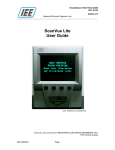
® ScanVue Interactive (Web Client) Kiosk User Manual M5000-02 ScanVue® 5000 Customer Interactive (Web Client) Kiosk User Manual (U.S. Patent No. 6,213,394 B1) IEE, INC. 7723 Kester Avenue Van Nuys, CA 91409 14-May-2015 Rev.C 1 ® ScanVue Interactive (Web Client) Kiosk User Manual M5000-02 NOTICES This document contains proprietary information shall not be used or reproduced or its contents disclosed in whole or in part, without the prior written consent of IEE, Inc. IEE, Inc. reserves the right to make improvements to the software described in this documentation at any time and without notice. The information contained herein is subject to change without notice and should not be construed as a commitment by IEE, Inc. The software described in this document is provided as a licensed item in conjunction with IEE, Inc. equipment. It may not be copied or distributed for use on other than the machines it was licensed for. DISCLAIMER OF ALL LIABILITIES IEE, Inc. shall have no liability or responsibility to you or any other person or entity with respect to any liability, loss or damage caused or alleged to be caused directly or indirectly by this documentation or the hardware or software described in it. This includes but is not limited to any interruption of service, loss of business or anticipatory profits or consequential damages resulting from the use or operation of such software or computer programs. All information in this manual was deemed correct at the time of printing. Updated versions of this manual will be published periodically and may be downloaded in Abode Acrobat (PDF) format from IEE’s website WWW.IEEINC.COM. Copyright © 2015 IEE, Inc. All Rights Reserved. 14-May-2015 Rev.C 2 ® ScanVue Interactive (Web Client) Kiosk User Manual M5000-02 STANDARDS CERTIFICATION The ScanVue® product described in this manual has been fully tested and certified by an independent testing laboratory and is compliant with the following international standards. UL Standard 60950 (ITE) listed product. CSA standard C22.2 No. 950 recognized product. RF Emmissions (Conducted): FCC CFR Title 47 part 15 Subpart B, Class A RF Emmissions (Radiated): CISPR 22 called out in FCC CFR Title 47 part 15 Subpart B, Class A EN55022, 2010/AC: 2011 Class A EN55024: 2010 EN61000-3-2: 2006 + A1: 2009 & A2: 2009 EN61000-3-3: 2008 The internal Wireless LAN PCIe Minicard is certified by the manufacturer to be compliant with the following standards: EN60950-1: 2006 + A11: 2009, EN 50385: 2002, EN 301 489-17 IEC 60950-1: 2001 FCC part 15B & part 15C CAUTIONS Caution: DO NOT DISPLAY A FIXED IMAGE FOR EXTENDED PERIODS OF TIME AS THIS MAY CAUSE LCD IMAGE PERSISTENCE PRODUCING PIXEL DISCOLORATION. 14-May-2015 Rev.C 3 ® ScanVue Interactive (Web Client) Kiosk User Manual M5000-02 TABLE OF CONTENTS TABLE OF FIGURES ................................................................................................................5 Chapter 1—Introduction.............................................................................................................6 Overview ..................................................................................................................................... 6 ® ScanVue 5000 (Web Client) Kiosk Description ......................................................................... 6 ® ScanVue 5000 (Web Client) Kiosk Operation ........................................................................... 7 Demo Mode ................................................................................................................................. 7 Interactive Mode (Home Web Page Image) ................................................................................ 7 Alternating Web Page Image Feature ......................................................................................... 8 Web Page Video Clip (Slideshow) Presentation ......................................................................... 8 4 Pushbutton Switches ................................................................................................................ 9 Configuration Example ..............................................................................................................10 ® ScanVue 5000 (Web Client) Kiosk Models .............................................................................11 Available Options ......................................................................................................................11 Configuration .............................................................................................................................12 Specifications ............................................................................................................................13 Interactive Device Options ........................................................................................................14 ® ScanVue Accessories .............................................................................................................14 Chapter 2—Getting Started .....................................................................................................15 Part 1 - SDK Installation ............................................................................................................16 Hardware and Software Required .............................................................................................16 ® ScanVue Documentation Access Instructions ........................................................................16 SDK Files and Software Installation ..........................................................................................16 SDK Contents............................................................................................................................17 Part 2 - Local PC (Host Server) Network Setup ........................................................................18 Introduction................................................................................................................................18 Network Setup Example Procedure (Windows 7) .....................................................................19 Part 3 – Demo Mode Test .........................................................................................................24 Instructions ................................................................................................................................24 Part 4 – Home Web Page (Interactive Mode) Test ...................................................................25 Sample Script / Image File Installation ......................................................................................25 Test Procedure ..........................................................................................................................25 Chapter 3—ScanVue® Connections .......................................................................................26 Connections For (PoE Power / Communication) ......................................................................26 Connections For (+12V Power / Ethernet Communication) .....................................................26 Connections For (+12V Power / Wi-Fi (802.11b/g) Communication) .......................................26 ® Mounting the ScanVue (Web Client) Kiosk .............................................................................28 Standard Wall Mount Installation ..............................................................................................28 Chapter 4—ScanVue® Web Client Configuration...................................................................29 UnitConfig Program ...................................................................................................................29 Modeset Program ......................................................................................................................31 ® ScanVue Web Client Kiosk Supported Modes ........................................................................32 Wireless Network Setup ............................................................................................................37 WEP Encryption Settings ..........................................................................................................37 WPA and WPA2 Encryption Settings ........................................................................................37 Chapter 5—Interactive Device Options ...................................................................................38 Serial Receipt Printer ................................................................................................................38 Magnetic Stripe Reader ............................................................................................................40 Touch Screen ............................................................................................................................40 14-May-2015 Rev.C 4 ® ScanVue Interactive (Web Client) Kiosk User Manual M5000-02 Appendix A—Configuring with Barcodes ................................................................................42 Barcode Scanner Settings ........................................................................................................42 ® Configuring ScanVue ..............................................................................................................42 Support Barcodes .....................................................................................................................44 Appendix B—Mounting Bracket Outline ..................................................................................47 TABLE OF FIGURES Figure 1—Configuration Info Screens 1 and 2 ............................................................... 12 Figure 2—Connector Location—Rear of ScanVue® ....................................................... 26 Figure 3—Ethernet / PoE Connector (RJ45) Pin Assignments ...................................... 27 Figure 4—Power Connector (DIN8F) Pin Assignments ................................................. 27 Figure 5—Unit Configuration (UnitConfig) Screen ......................................................... 30 Figure 6— Example WPA / WPA 2 Encryption Settings ................................................ 37 Figure 7—Wiring a Serial Printer ................................................................................... 39 Figure 8—Interface Connector Pin Assignments ........................................................... 41 Table 1—Barcode Configuration Labels ........................................................................ 43 Figure 9—Slimline Wall Mount Bracket ......................................................................... 47 14-May-2015 Rev.C 5 ® ScanVue Interactive (Web Client) Kiosk User Manual M5000-02 Chapter 1—Introduction Overview This manual provides instructions for configuration and operation of the IEE ScanVue® 5000 Interactive (Web Client) Kiosk. Included is a description of the basic functions and features of the hardware along with a description of how to physically install the unit in its intended location, set it up to operate on your specific network, configure your network, and interface the IEE ScanVue® to a host web server. The following chapters describe how to: Setup and install a local desktop or laptop PC with IEE Configuration programs. Configure ScanVue® using IEE configuration program UnitConfig or Modeset. Display web images and short Animated GIF video clips when directed to the host web server network by entering URL’s using IEE configuration program UnitConfig or Modeset. ScanVue® 5000 (Web Client) Kiosk Description ScanVue® 5000 (Web Client) Kiosk is a mini kiosk designed to scan bar coded merchandise, obtain and display current in-store promotional information. Retail consumers are provided this information to help make informed purchasing decisions. The QVGA (320x240 pixel) resolution display can be used to present in-store merchandising and multimedia presentations for promoting seasonal sales and upcoming events to help retail consumers make informed purchasing decisions. The programmable function buttons and available touch screen enhance in-store applications and allow customer interaction. Image formats supported are GIF, JPEG and PNG. Short animated GIF clips are also supported. Content developers are encouraged to use familiar design tools, such as HTML, JavaScript and PHP scripts to create images and interactive applications. ScanVue® Web Client Kiosk is a network–connected device supporting 10/100 Base-T Ethernet, Power-Over Ethernet (PoE) and 11Mbps (IEEE 802.11b) Wi-Fi communication. The contemporary housing design merges well with almost any store décor and custom color combinations are available if the units are ordered in sufficient quantities. The electronics package is completely contained in a high impact ABS injection molded case. 14-May-2015 Rev.C 6 ® ScanVue Interactive (Web Client) Kiosk User Manual M5000-02 ScanVue® 5000 (Web Client) Kiosk Operation Demo Mode The default “as-shipped” setting Demo mode provides a way to showcase the ScanVue® Web Clients’ abilities without requiring a physical connection to a host computer. An internal web server with a price-lookup database application loaded with several items is embedded in ScanVue® Web Client Kiosk. Refer to Chapter 2 - Part 3 for Demo Mode Test. To exit Demo Mode and setup for Interactive Mode to run on your network, reconfigure the Web Client and change the HomeURL and HomeURL2 to your network home pages. Refer to Interactive Mode section below and Web URL Configuration section in Chapter 4. Interactive Mode (Home Web Page Image) Mode Setting: (HomeURL) Interactive Mode is the interface between the user (customer) and the Web Client. A retail store unit, for example, running a product item price verifier, loyalty program, gift registry and other retail applications will be operating in this normal operation mode. With HomeURL specified, ScanVue® Web Client expects to find the host server web page to load and display. Web page images or short animated GIF clips are displayed continuously (with HomeURL specified) during Idle Stage until item barcode scan. HTML and PHP scripts are used for presenting images and video clips. Idle stage Image resumes after a programmed timeout. (A single image may be preferred but is not recommended due to possible LCD image persistence “pixel discoloration”). Once the home page loads, control resides primarily with the web server application. The Web Clients’ page display will persist until the either web server directs it to another page, a new URL is generated by scanning a barcode, pressing a pushbutton or the POStimeout value is exceeded in which case it will return to the homepage. Item Barcode Scan: During normal operation (Interactive Mode), customer scans product UPC barcode generating a URL with the UPC number merged with the scanner prefix and suffix specified. This unique URL is used to lookup and retrieve the specific items properties. The Web Server based product price and description information in the form of QVGA (320x240) images are then displayed on the ScanVue® Web Client. Scanning a barcoded item generates a URL with the SKU or UPC# merged with the scanner prefix and suffix specified. This unique URL can be used to lookup and retrieve the specific items properties from a table. For example; the URL http://mysite/pricelookup/123456B.html will be directed to the mysite domain, pricelookup directory. The application will retrieve the price and description data for item 123456B, format it and display its contents. In this example URLprefix = /mysite/pricelookup; URLsuffix =.html and the item SKU or UPC barcode = 123456B. 14-May-2015 Rev.C 7 ® ScanVue Interactive (Web Client) Kiosk User Manual M5000-02 Alternating Web Page Image Feature Mode Settings: (HomeURL + HomeURL2) Two web page images set using HomeURL and HomeURL2 mode settings (using HTML and PHP script) alternate during Idle Stage with programmed timeout until item barcode scan. Alternating idle stage images resume after a programmed timeout. (Possible LCD image persistence is avoided using this feature). 2 alternating graphic images can be as simple as the image below shown in complementary colors. Alternating the two images every 20 seconds is default. JOES HARDWARE JOES HARDWARE SCAN HERE SCAN HERE Web Page Video Clip (Slideshow) Presentation Mode Settings: (HomeURL or HomeURL2) A sequence of 30 or more animated .gif images set using either HomeURL or HomeURL2 mode settings (using HTML and PHP script) are displayed during Idle Stage simulating slideshow until item barcode scan. Idle stage images resume after a programmed timeout. The animated GIF should not exceed 4 Mbyte in size. Depending on the complexity of each image in the animated GIF, the presentation allows for more than 30 images. If more complex images are desired, a simple web-server driven sequence of images can be implemented on the home page. For example, the home page contains a pointer to a GIF or JPEG image with a meta-tag in the header specifying how long to display the page and which page to go to next. An almost infinitely long chain of images or a loop could be created. 14-May-2015 Rev.C 8 ® ScanVue Interactive (Web Client) Kiosk User Manual M5000-02 4 Pushbutton Switches The four pushbuttons are treated as four separate input devices. Pushing any one of the 4 pushbuttons generates a URL with the pushbutton number merged with the btPrefix and btSuffix specified. The pushbuttons are numbered 1 to 4 from left to right. PushButton Push button 1 (leftmost) Push button 2 (2nd from left) Push button 3 (3rd from left) Push button 4 (rightmost) Push button release Value (Mask Setting) fffffff1h fffffff2h fffffff4h fffffff8h fffffff0h For example: Pressing pushbutton 2 could generate the following URL (depending on settings). Press pushbutton 2 http://mysite.com/buttons.php?val=fffffff2 Releasing pushbutton 2 could generate the following URL (depending on settings). Press pushbutton 2 http://mysite.com/buttons.php?val=fffffff0 Event Start mode setting default is 0000000F. This is a bitmap indicating all 4 buttons are activated). A start event will be generated when a button is pressed. Refer to ScanVue® Supported Modes section for EventStart requirements. 14-May-2015 Rev.C 9 ® ScanVue Interactive (Web Client) Kiosk User Manual M5000-02 Configuration Example Default Configuration for Demo The ScanVue® Web Client is shipped configured in Demo Mode. Refer to Demo Mode section. Default Settings are as follows: eventStart HomeURL HomeURL2 URLPrefix btPrefix btSuffix =0000003F =http://localhost/index1.html =http://localhost/index2.html =http://localhost/barcode.php?val= =http://localhost/buttons.php?val= =(Not Set) The example above puts the ScanVue® Web Client into internal Demo Mode. With HomeURL specified, ScanVue® Web Client expects to find the embedded web page to load and display. Test Example Configuration (Web Page Operation) eventStart HomeURL HomeURL2 URLPrefix btPrefix btSuffix =0000003F =http://10.0.10.13/faucet.html =http://10.0.10.13/circle.html =http://10.0.10.13/barcode.php?val= =http://10.0.10.13/buttons.php?val= =(Not Set) The example above puts the ScanVue® Web Client into Interactive Mode which is the interface between the user (customer) and the Web Client. A retail store unit, for example, running a product item price verifier, loyalty program, gift registry and other retail applications will be operating in this mode. With HomeURL specified, ScanVue® Web Client expects to find the host server web page to load and display. HomeURL must be set to start web page for producing primary image or animated GIF clip. HomeURL2, if used, is set to secondary web page for producing alternate image or animated GIF clip. Customer scans product UPC barcode generating a URL with the UPC number merged with the scanner prefix and suffix specified. This unique URL is used to lookup and retrieve the specific items properties from a table. The Web Server based product price and description information in the form of QVGA (320x240) images are then displayed on the ScanVue® Web Client. Changing a mode setting value using UnitConfig modifies the saved configuration. ScanVue® retains the new settings in non–volatile memory. The ScanVue® Web Client supports input devices—barcode scanner, pushbuttons, optional magnetic stripe reader and optional digital touchscreen. 14-May-2015 Rev.C 10 ® ScanVue Interactive (Web Client) Kiosk User Manual M5000-02 ScanVue® 5000 (Web Client) Kiosk Models ScanVue® Model 5000 Web Client Kiosk is available with a SVGA color graphics LCD display. The ScanVue® LCD family consists of a number of different models that appear externally identical but have different features: The ScanVue® Web Client Kiosk model 5000-0010 is basic model with 10/100 BaseT Ethernet communication. The ScanVue® Web Client Kiosk model 5000-0110 has 11Mbps (IEEE 802.11b) Wi-Fi communication along with 10/100 BaseT Ethernet communication. Model Number Scheme Model #: XXXX-XXXX-XX 1st 4 Digits: Model 5000 Series XXXX-XXXX-XX 5000 LCD - 5.7” QVGA Display 2nd 4 Digits: ScanVue Configuration Options XXXX- X X 1 0-XX (4) Buttons Wi-Fi Last Digit: 0 = No 1 = Yes 0 = No 1 = Yes Special Order: XXXX-XXXX-X X (OPTIONAL) Printer Kit 2 Custom Color X Please call for custom color or special request requirements ScanVue Web Client models are available with Power-Over-Ethernet (PoE) 10/100 BaseT communication or Ethernet with power input for 11-29 VDC power. A 12 VDC 2.5A (30W) Power Supply is available as an option. Available Options For available device option requirements, refer to Interactive Device Options section. For power and communication requirements, refer to Specifications section. 14-May-2015 Rev.C 11 ® ScanVue Interactive (Web Client) Kiosk User Manual M5000-02 Configuration ScanVue® Configuration Options There are 2 ways to configure a ScanVue® unit: 1. Commands sent across the network using the UnitConfig or Modeset programs. (ScanVue® must be able to communicate with the server on the network before configuration settings can be changed on the network). 2. Scan special purpose configuration barcodes. Refer to Appendix A for instructions. UnitConfig the graphical, table oriented version of modeset provides the easiest way to change the configuration of a unit on the network (as opposed to scanning barcodes or sending modeset DOS commands. UnitConfig may be installed on a desktop or laptop computer for setting up ScanVue® units without a large network complicating it. You will need a network interface card (NIC) installed in your PC and configured properly to communicate with ScanVue®. Configuration Info Screens When ScanVue® boots up, two configuration status screens (Fig. 1) are sequentially displayed which show the current settings of the unit. Each screen is displayed for 10 seconds then the unit will load the slideshow from the server and start running. These screens can be displayed at any time by scanning ‘Info Screen 1’ and ‘Info Screen 2’ bar codes shown in Appendix A under Support Barcodes. Wireless RF configurations display brown text on a light green background and hardwired Ethernet units display yellow text on a blue background. Refer to Chapter 5 for detailed information on how to configure a ScanVue®. Figure 1—Configuration Info Screens 1 and 2 14-May-2015 Rev.C 12 ® ScanVue Interactive (Web Client) Kiosk User Manual M5000-02 Specifications Display: QVGA (320x240 pixel) color graphics 5.7” Diagonal LCD display Network Server Computer Requirements: MS Windows, Unix, Linux, VAX or any other platform that runs a TCP/IP network Supported Operating Systems: Windows 98, ME, 2000, NT, XP, Windows 7 (32-Bit), Unix, Linux and Open VMS Power Options: Wi-Fi and Ethernet Models: 11-29 VDC, 10 W typ. (24 VDC Nominal) PoE Hardwired Models: 48 VDC, 10 W typ. (IEEE 802.3af compliant) Communication Options: 11Mbps (IEEE 802.11b) Wi-Fi * Ethernet 10/100 Base-T Power-over-Ethernet (PoE) Interactive Devices: 4 front panel push button interactive switches Input Device Options: An external RS232 serial port is available via an optional Y cable that supports a serial receipt printer or other serial device. 2 USB ports – (For any desired future use such as MSR, please contact Sales) 1D/2D Barcode Scanner: Supports any 1D and 2D bar codes including PDF417 codes. UPC and NCR prefix support. Web Client Kiosk OS: Embedded Linux Web Page Image Support: Image Format: GIF, Animated GIF, JPEG, PNG Image Resolution: 320x240 Animated GIF Image Memory: 4 MB (More than 30 images) Input Data Steering: Configurable URL for each device type Configuration Setup: On Line: UnitConfig ● Off Line: Barcodes Web Application: Standard HTML 4.0, Javascript, PHP Security: WEP* ● WPA - WPA-PSK, TKIP ● WPA2 - WPA-PSK, CCMP Mounting Options: Standard wall-mount bracket Tools: SDK (software developers kit) includes ScanVue® configuration programs (UnitConfig and Modeset), Sample code, sample graphic image files and user manual ® *NOTE: WEP (Wireless Equivalent Privacy) encryption continues to be supported by ScanVue , however, the recommended solution to WEP security problems is to switch to WPA2 (Wi-Fi Protected Access). 14-May-2015 Rev.C 13 ® ScanVue Interactive (Web Client) Kiosk User Manual M5000-02 Interactive Device Options Fujitsu model FP-1000 thermal 3” receipt printer (Contact IEE Sales for this option) (Serial RS-232 communication - Requires optional Y cable – The printer is powered separately) - ® Serial RS-232 Communication - ScanVue receives pre-formatted data and control codes from a printer driver resident on the network host, which it passes, unmodified, through DIN 8 Connector (Serial RS-232) to the printer. Default Communication is 9600 BAUD, 8-bit, no Parity and 1 stop bit. 3 track USB Magnetic stripe reader (Contact IEE Sales for this option) Resistive touch screen (Contact IEE Sales for this option) ScanVue® Accessories +12 VDC 2.5A (30W) Power Supply (IEE P/N 39055-01) with a standard 8 pin DIN male connector to power ScanVue® (Typically not included with ScanVue®). The input is universal 90-264VAC/50-60Hz and the power supply has global certifications. 48 VDC, 10 W typ. (IEEE 802.3af compliant) Power Over Ethernet (PoE) Injector (IEE P/N 90180-01) with dual RJ45 jacks (J2 Ethernet IN - J1 Power / Ethernet OUT to ScanVue®) - (Typically not included with ScanVue®). The input is 100-250VAC/47-63Hz. Printer interface cable for Fujitsu model FP-1000 or equivalent printer (IEE P/N 38578-01) Y cable for ScanVue® with Fujitsu model FP-1000 or equivalent printer (IEE P/N 70665-01) Y cable, RS232 Universal with DB9F connector (IEE P/N 38516-07) 6' DC power extender cable with DIN8F to DIN8M connectors (IEE P/N 37082–72) 14-May-2015 Rev.C 14 ® ScanVue Interactive (Web Client) Kiosk User Manual M5000-02 Chapter 2—Getting Started This Chapter describes how to set up and operate a factory default IEE ScanVue® 5000 Web Client Kiosk on your laptop or desktop PC (Host Server). Several programs are installed that let you demonstrate the capabilities of the ScanVue® 5000 Web Client Kiosk and make use of the tools and utilities provided in the SDK package downloaded from IEE’s web site. These programs can be used as demonstration tools. Part of the process is to change the network settings of your computer so that it can communicate with a factory default ScanVue® 5000 Web Client Kiosk. If you need to set your computer back to its original settings, note down all the original settings before you make the changes. If your computer is already setup to operate on a private company network IEE recommends consulting with your IT group before performing this procedure. 14-May-2015 Rev.C 15 ® ScanVue Interactive (Web Client) Kiosk User Manual M5000-02 Part 1 - SDK Installation Hardware and Software Required Laptop (or desktop) computer with Windows 98/ Me / 2000 / NT / XP Pro / 7 LAN system with TCP/IP network protocol. Router or switch for connecting ScanVue® 5000 Kiosk to network. Category 5 standard straight cable when using a router or switch (or a “crossover” network patch cable when connecting directly to Host Server) IEE ScanVue® 5000 Web Client Kiosk SDK ScanVue® Documentation Access Instructions Please follow link for available ScanVue® Web Client Kiosk documentation and Software Developers Kit (SDK) from IEE web site: http://ieeinc.com/downloads 1) To download Software Developer’s Kit for setting up a PC as ScanVue® Station Server with utilities, click on SDK_5000_WC.zip and save to your choice directory. 2) Extract all files from SDK_5000_WC.zip. 3) Refer to SDK Contents section for description of folders and their contents. SDK Files and Software Installation Before installing the ScanVue® programs, IEE highly recommends installing the latest updates or service packs to the operating system you are using. 1) Copy the entire POS folder into C:\ directory on your host system or any other folder you choose. 2) Refer to instructions described in Part 2 of this Chapter to prepare the host server for communication with ScanVue® 5000 Web Client Kiosk. 3) Refer to instructions described in Part 3 of this Chapter to perform local demo mode test (default “as-shipped” setting) using sample images internal to ScanVue® Kiosk. 4) Refer to instructions described in Part 4 of this Chapter to perform home web page test using sample script files and images located on host server htdocs folder copied from SDK htdocs_kiosk folder. 14-May-2015 Rev.C 16 ® ScanVue Interactive (Web Client) Kiosk User Manual M5000-02 SDK Contents Documentation Folder Contains Manual and support documentation POS Folder UnitConfig A GUI program used for setting up ScanVue® from the network. Written in VisualBasic, the .exe, VB sources and an OCX are provided. When installed the program has a wrench logo. Modeset is the associated DOS program modeset.exe Command line utility for setting ScanVue modes instead of UnitConfig. (Also named ms.exe) htdocs-kiosk Folder Contains support folders, sample test images and sample HTML and php scripts to be copied into Host Web Server htdocs directory for test purposes Test Directory: c:\program files\apache software foundation\apache 2.0\htdocs Application Examples Folder Modeset Examples Contains DOS command line batch program examples using Modeset utility that can be used to configure a group of ScanVue units at one time UnitConfig Driver Installation (Win7) Folder Windows 7 UnitConfig Driver Installation.pdf Driver registration procedure required for running UnitConfig and Modeset programs on Windows 7 (32 Bit and 64 Bit) OS (32 Bit OS Drivers): richtxt32.ocx Files required to be registered in Win7 (64Bit OS) msflxgrd.ocx to run the UnitConfig program. comdlg32.ocx Files registered are located in directory: c:\windows\system32\ (64 Bit OS Drivers): richtxt32.ocx Files required to be registered in Win7 (64Bit OS) msflxgrd.ocx to run the UnitConfig program. comdlg32.ocx Files registered are located in directory: c:\windows\syswow64\ 14-May-2015 Rev.C 17 ® ScanVue Interactive (Web Client) Kiosk User Manual M5000-02 Part 2 - Local PC (Host Server) Network Setup Introduction ScanVue® 5000 Web Client Kiosk comes factory defaulted with IP address set for DHCP. This is for automatically obtaining IP addresses assigned from a network server when performing installations. The ScanVue® will default to 192.168.0.1 if you don’t have a DHCP server installed on your network. This section describes how to setup a local desktop or laptop PC (Host Server) to communicate with a factory default ScanVue® 5000 Kiosk. A router is expected to be installed on your network with DHCP server enabled. The Host Server must be set for Ethernet communication allowing for further configuration using IEE’s configuration program UnitConfig or Modeset. See Chapter 4 for ScanVue® Configuration. This process is specific for Windows 7 OS, however, Windows OS (98/ NT, 2000, and XP) are also supported. Your computer will be configured as a network server with one client. If you need to set your computer back to its original settings, note down all the original settings before you make the changes. If your computer is already setup to operate on a private company network, IEE recommends consulting with your IT group before performing this procedure. (Note: If a ScanVue® is connected directly to a PC without a router or switch, a crossover cable must be used). ScanVue® Factory default network settings: IP Address: Sub-Net Mask: WINSserverIP: Unit ID: 14-May-2015 Rev.C (via DHCP) 255.255.0.0 10.0.10.13 ScanVue Username: GUEST Windows Serv: SVSERVE password: (Not Set) 18 ® ScanVue Interactive (Web Client) Kiosk User Manual M5000-02 Network Setup Example Procedure (Windows 7) 1. Preliminary Disable your Windows 7 Firewall or Anti-Virus. 2. Network Security Settings Enter Control Panel All Control Panel Items Network and Sharing Center Under “View your active networks” section, click “Local Area Connection”. Verify network communication is established with status similar to the following example. (Note: Host Server obtains IP address from router DHCP server referenced in example as IPv4 Address 10.0.10.79) Close Network and Sharing Center window. 14-May-2015 Rev.C 19 ® ScanVue Interactive (Web Client) Kiosk User Manual M5000-02 3. Change Computer Name Enter Control Panel All Control Panel Items System Computer Name tab. Double-click Change settings. In the System Properties window, click Change button to bring up Computer name / Domain Changes window. Enter SVSERVE in Computer name field. Note: Workgroup must be selected with any description, provided it is 8 characters or less, no spaces. Click OK button. Follow displayed instructions to restart computer. 14-May-2015 Rev.C 20 ® ScanVue Interactive (Web Client) Kiosk User Manual M5000-02 4. Enable User Guest Account Enter Control Panel All Control Panel Items User Accounts to display administrator account. Click on “Manage another account” to show Guest account. If the Guest icon says Guest account is off, click the Guest icon to display the following window. 14-May-2015 Rev.C 21 ® ScanVue Interactive (Web Client) Kiosk User Manual M5000-02 Click Turn On button to enable Guest account. Guest account should then be indicated as follows: Close the Manage Accounts window. 14-May-2015 Rev.C 22 ® ScanVue Interactive (Web Client) Kiosk User Manual M5000-02 5. Allow ScanVue “Guest” Account on Host Server Network For Windows 7, Guest account is denied access on the network by default. This process removes Guest as a denied account from network server security settings policy. Click “Start” In Search programs and files field, type and enter GPEDIT.MSC. The Local Group Policy Editor will open. Enter Computer Configuration Windows Settings Security Settings Local Policies User Rights Assignment Double-click on Deny Access to the Computer from the Network. (See window below) Guest account may be shown as indicated below: With SVSERVE\Guest highlighted, click Remove to remove Guest then click OK. Close Local Group Policy Editor. Network setup is completed. 14-May-2015 Rev.C 23 ® ScanVue Interactive (Web Client) Kiosk User Manual M5000-02 Part 3 – Demo Mode Test Description In the default (Demo Mode) configuration, the ScanVue® Kiosk will boot to the internal home pages HomeURL (Default URL: http://localhost/index1.html) and HomeURL2 (Default URL: http://localhost/index2.html). The ScanVue® Kiosk will then be ready to accept the demo barcode scans and button presses while two home pages are cycled between two graphic images. The touch screen is active to demonstrate functionality. For units that have been re-configured, scan the Return to Factory Defaults barcode tag then the Save and Reboot tag, which will return the ScanVue® Web Client Kiosk to its factory default Demo Mode operation. Instructions Scan sample barcodes shown below and verify represented sample graphic images. The internal (local) web server application will lookup the barcode number for the item scanned and display the graphic image or text data retrieved from the lookup tables. To exit Demo Mode and setup for Interactive Mode to run on your network, reconfigure the Web Client and change the HomeURL and HomeURL2 to your network home pages. Refer to Interactive Mode section in Chapter 1 and Web URL Configuration section in Chapter 4. DEMO & INTERACTIVE MODE TEST BARCODES 14-May-2015 Rev.C 24 ® ScanVue Interactive (Web Client) Kiosk User Manual M5000-02 Part 4 – Home Web Page (Interactive Mode) Test Description In the Interactive Mode configuration, the ScanVue® Kiosk will boot to the host server web pages HomeURL and HomeURL2. The ScanVue® Kiosk will then be ready to accept test barcode scans and button presses while the two home pages are cycled between the two URL pages. Sample Script / Image File Installation 1) Make a backup of your Host Web Server htdocs directory. 2) Copy the entire htdocs-kiosk folder and sub-folders into htdocs folder. htdocs folder will contain the example HTML and php scripts referencing sample images for the ScanVue® Web Client to display. Test Procedure 1) Connect ScanVue® to Host Server Network as described in Chapter 3. 2) Apply power—the ScanVue® unit will start its boot–up sequence. 3) During boot up and connection to Host Server, note the IP address of the ScanVue® reported on the Info Screen. 4) Using UnitConfig or modified batch program using modeset utility (see Application Examples/Modeset Examples/Sample Program folder in SDK), change following mode settings as indicated (<Server IP Addr> is Host Server Address): HomeURL = HomeURL2 = URLPrefix = btPrefix = http://<Server IP Addr>/faucet.html http://<Server IP Addr>/circle.html http://<Server IP Addr>/barcode.php?val= http://<Server IP Addr>/buttons.php?val= 5) Commit settings and reboot ScanVue®. If Host Server has been set up as previously instructed, you should see alternating HomeURL (dripping faucet) and HomeURL2 (rainbow with bird) images directed by faucet.html and circle.html script files located in htdocs directory. 6) Scan sample barcodes shown on previous page and verify sample graphic images directed by barcode.php script and HTML script files located in htdocs directory. 7) Press all four pushbutton switches and verify sample graphic images (button1.jpg to button4.jpg) for each switch directed by buttons.php script file located in htdocs directory. 14-May-2015 Rev.C 25 ® ScanVue Interactive (Web Client) Kiosk User Manual M5000-02 Chapter 3—ScanVue® Connections Refer to (Figure 2) for ScanVue® rear connections. Refer to (Figure 3) for Ethernet pin assignment. Refer to (Figure 4) for +12Vdc power pin assignment. Connections For (PoE Power / Communication) PoE Hardwired connection requires only 1 cable: CAT-5 standard straight Ethernet cable 48 Vdc (IEEE 802.3af compliant) Connections For (+12V Power / Ethernet Communication) Ethernet only (non-PoE) connection requires 2 cables: +12 Vdc power to ScanVue® DIN8F connector. CAT-5 standard straight Ethernet cable to ScanVue® Ethernet Interface connector (or a “crossover” network patch cable when connecting directly to Host Server) Connections For (+12V Power / Wi-Fi (802.11b/g) Communication) Wi-Fi models require DIN8 power and hardwired Ethernet connection (required for network settings configuration): +12 Vdc power to ScanVue® DIN8F connector. CAT-5 standard straight Ethernet cable to ScanVue® Ethernet Interface connector (or a “crossover” network patch cable when connecting directly to Host Server) Figure 2—Connector Location—Rear of ScanVue® 14-May-2015 Rev.C 26 ® ScanVue Interactive (Web Client) Kiosk User Manual M5000-02 Ethernet / PoE Connector (RJ45) Pin Assignments The following table identifies the locations for the Ethernet port pins and PoE power pins (if used). Ethernet RJ45 Pin Assignment PIN. NO. 8-Pin RJ45 Pinout FUNCTION 1 TXD (+) 2 TXD (-) 3 RXD (+) 4 + POWER 5 + POWER 6 RXD (-) 7 - POWER 8 - POWER Figure 3—Ethernet / PoE Connector (RJ45) Pin Assignments Power Connector (DIN8F) Pin Assignments The following table identifies the locations for the +12 Vdc Power pins. Power DIN8F Assignment PIN. NO. Power DIN8F Pinout FUNCTION 1 GND 2 POWER +12 VDC (2.5A) 3 INTERNAL CONNECTION 4 INTERNAL CONNECTION 5 INTERNAL CONNECTION 6 INTERNAL CONNECTION 7 POWER +12 VDC (2.5A) 8 GND Figure 4—Power Connector (DIN8F) Pin Assignments 14-May-2015 Rev.C 27 ® ScanVue Interactive (Web Client) Kiosk User Manual M5000-02 Mounting the ScanVue® (Web Client) Kiosk Standard Wall Mount Installation A single slimline wall mount bracket is provided as a standard item shipped with the ScanVue® 5000 Kiosk (See Appendix B for actual dimensions). The wall bracket can be mounted on any type of flat vertical surface using the 6 mounting bosses with holes. The bracket can also be mounted by a special double-sided tape to a glass column or wall. Mounting hardware is not provided as the material used in the vertical wall can vary depending on the location chosen and either wood screws or toggle bolts or equivalent are recommended. Do not use wood screws or sheet metal screws in drywall—they will not hold the weight of the unit. Note: contact factory for recommendation of double sided tape—do not use the kind you might find in the local drug store or hardware store. The wall mount bracket is removed from the rear of the unit, sliding it up and off of the 4 vertical tongues, and mounted to the wall, column or endcap. A hole is provided in the bracket for bringing the power and/or network connection through from the wall or column. The ScanVue® unit is pushed close to the wall about 1” above the bracket tongues. Push it downward until the 4 tongues mate securely with their counterpart slots in the rear of the housing. Tighten the 2 locking screws through the slots in the housing until snug—this will prevent anybody from removing the unit from its mount. 14-May-2015 Rev.C 28 ® ScanVue Interactive (Web Client) Kiosk User Manual M5000-02 Chapter 4—ScanVue® Web Client Configuration UnitConfig Program Configuring ScanVue® units over the network requires a GUI program called Unit Config or Modeset program described below. Unit Config provides a simple graphical way to query and configure any ScanVue® unit using mode commands. Changes can also be made off–line that will allow the unit to connect to the network using Configuring with Barcodes method (See Appendix A) without requiring the PC. Generally, configuration by special barcode is kept for those occasions when a devices network configuration is incompatible with the local network. Once the unit is network compatible the rest of the configuration can be done through UnitConfig. Using UnitConfig Start UnitConfig blank. Button / Field program. When UnitConfig program is first started, all program fields are Instruction Enter the IP address of the ScanVue® unit you wish to change in the Unit IP Address field Restart Unit Click the Read Modes button. All the Modes and their Content (values) will be read from the subject unit and displayed as shown in Figure 5 To change a mode value; highlight the New Content field in the same row as the mode you want to change by clicking on it. Enter the new value in the field and click the Set Mode button. If the value is accepted, the field and the button will turn green. If it is not accepted, the field and button will turn red. The light color area at the bottom of the screen will display context sensitive help message for each mode as the mode is highlighted. For some modes, the values available are indicated in this area. Now click the Commit button. This will commit the change to memory in the ScanVue® unit. Multiple changes can be made before committing them. If any of the changes are not accepted, the Set Mode button will turn red and those changes marked in red were not made. Clicking the Close button will blank all fields allowing a new IP address for another unit to be entered Clicking the TextReset button will apply changes made to text modes so they can be seen immediately. As with other modes, the changes are not permanently stored until the Commit button is clicked The SaveToFile button will save the setup to a text file where it can be stored and printed if necessary. This is usually done for troubleshooting or maintaining hard copy records of each unit’s configuration The Restart Unit button will cause a ‘soft boot’ of the selected unit Exit The Exit button closes the UnitConfig program Read Modes Set Mode Commit Close TextReset SaveToFile 14-May-2015 Rev.C 29 ® ScanVue Interactive (Web Client) Kiosk User Manual M5000-02 Figure 5—Unit Configuration (UnitConfig) Screen Configuration Notes 1. Mode names are NOT case sensitive. ® 2. Set DHCP in unitIP to change to (via DHCP) for ScanVue to obtain an IP Address from a network DHCP server. 3. Most modes can be set to factory default or (Not Set) value by entering double quote [“”] or [–default–] as the value. 14-May-2015 Rev.C 30 ® ScanVue Interactive (Web Client) Kiosk User Manual M5000-02 Modeset Program Modeset (a DOS command line program associated with UnitConfig) may be used in place UnitConfig to query and set modes via a batch program file or directly from the DOS prompt. Examples: The following command sets ScanVue unit (IP address: 10.0.30.134) to values within TEST01.INI file, then commits change to memory and restarts ScanVue: modeset -s -fTEST01.INI -c -r 10.0.30.134 The following command sets ScanVue to specific value (Wireless=TRUE): modeset -iWireless=True 10.0.30.134 Modeset command can also be used to batch program a group of ScanVue units at one time. Refer to Modeset Example folder in the SDK. Modeset command by itself lists all non-hidden modes and their values ModeSet Options: 14-May-2015 Rev.C 31 ® ScanVue Interactive (Web Client) Kiosk User Manual M5000-02 ScanVue® Web Client Kiosk Supported Modes Notes: 1. Modes viewed in UnitConfig application that are NOT listed in this manual are used for other ScanVue models and do not apply to the Web Client Kiosk model. 2. Mode names are NOT case sensitive. ® 3. Set DHCP in unitIP to change to (via DHCP) for ScanVue to obtain an IP Address from a network DHCP server. 4. Most modes can be set to factory default or (Not Set) value by entering double quote [“”] or [–default–] as the value. Fixed Unit Identification Configuration Mode Version DateTime BuildInfo ProductName SerialNumber QueryViaBrowser Description Software version number; read–only Not available! The date and time of the software release in the format YYYYMMDD; read–only. Default “ScanVue”; read–only. Contains the unique serial number for the unit; read–only. IEE factory setup (Always TRUE for Web Client browser configuration) Default xx.xx YYYYMMDD ScanVue 999999 TRUE Note: This configuration setting is not available for ScanVue models containing software prior to version (11.01 - “ver. 1.008”). User Configurable Unit Identification Configuration Mode UnitID UnitIP UnitMask GatewayIP UserName Password 14-May-2015 Rev.C Description The host name of the unit, 19 characters maximum The IP address of the unit, in standard IP dotted notation. Unit IP default is 192.168.0.1 with no connection and with no DHCP server available. The network mask for the unit, in standard IP dotted notation. The IP address of the gateway machine, in standard IP dotted notation. Required only if access to the various hosts must be routed on the LAN The username ScanVue uses when logging into the file server The password ScanVue uses when logging into the file server 32 Default ScanVue (via DHCP) or… 192.168.0.1 255.255.0.0 10.0.10.13 GUEST (Not Set) ® ScanVue Interactive (Web Client) Kiosk User Manual M5000-02 Web URL Configuration Configuration Mode HomeURL HomeURL2 HomeURLTimeout URLPrefix URLSuffix btPrefix btSuffix msrPrefix msrSuffix 14-May-2015 Rev.C Description Default Complete URL defining the primary home or start page. Must be a valid web page. Typically, this page might load an animated GIF “slideshow”. With default HomeURL, the Web Client cycles between HomeURL and HomeURL2. Be sure to include the port number if other than port 80 (or 443 for https:// lookups), as in http://mysite.com:83/. http://localhost /index.html Example: http://mysite.com/index.html Complete URL defining the secondary home or start page. Must be a valid web page. Typically, this page might load an animated GIF “slideshow”. With default HomeURL, the Web Client cycles between HomeURL and HomeURL2. Be sure to include the port number if other than port 80 (or 443 for https:// lookups), as in http://mysite.com:83/. Example: http://mysite.com/index2.html Delay in seconds between HomeURL and HomeURL2 pages. (Timeout of 20 seconds is a fixed setting) Prefix for the barcode scanner. Any legal full or partial URL is acceptable. Example: http://mysite.com/barcode.php?val= Suffix for barcode scanner. Any legal URL suffix will suffice. May be left blank. Prefix for 4 pushbuttons. Any legal full or partial URL is acceptable. Example: http://mysite.com/buttons.php?val= Suffix for 4 pushbuttons. Any legal URL suffix will suffice. May be left blank. Prefix for Magnetic Stripe Reader (MSR). Any legal full or partial URL is acceptable. Example: http://mysite.com/msr.php?val= Suffix for MSR. Any legal suffix will suffice. May be left blank. 33 http://localhost /index2.html 20 http://localhost /barcode.php? val= (Not Set) http://localhost /buttons.php?v al= (Not Set) http://localhost /msr.php?val= (Not Set) ® ScanVue Interactive (Web Client) Kiosk User Manual M5000-02 Wireless Encryption Configuration Configuration Mode WEPEncryption WEPKey1 WEPKey2 WEPKey3 WEPKey4 WEPKeyIndex UseWPA wpaScanSsid wpaKeyMgmnt wpaPairwise wpaGroup wpaEAP wpaPSKPassphrase wpaIdentity wpaPassword wpaCACert wpaPrivateKey wpaPrivateKeyPasswd wpaPhase1 wpaPhase2 wpaProto wpaCACert2 wpaClientCert2 wpaPrivateKey2 wpaPrivateKey2Passwd 14-May-2015 Rev.C Description WEP Encryption: Open40, Open128, Shared40, Shared128, None WEP Encryption Key 1: 10 or 26 hex digits WEP Encryption Key 2: 10 or 26 hex digits WEP Encryption Key 3: 10 or 26 hex digits WEP Encryption Key 4: 10 or 26 hex digits Select the active WEP key, 1-4 WPA Enable: TRUE or FALSE Scan for SSID (Usually set for TRUE) Default None WPA Key management: WPA-EAP, WPA-PSK, IEEE8021X, None WPA Pairwise: CCMP, TKIP, None WPA Group: CCMP, TKIP, WEP104, WEP40, None WPA EAP: TTLS, PEAP, TLS, None WPA PSK passphrase (password) WPA identiry string WPA SSH CA certificate path (ex: /etc/cert/ca.pem) WPA SSH client certificate path (ex: /etc/cert/user.pem) WPA SSH private key path (ex: /etc/cert/user.prv) WPA private key password WPA phase 1 string (ex: peaplabel=0) WPA phase 2 string (ex: auth=MSCHAPV2) WPA proto value: WPA2, WPA, None WPA SSH CA certificate 2 path (ex: /etc/cert/ca2.pem) WPA SSH client certificate 2 path (ex: /etc/cert/user.pem) WPA SSH private key 2 path (ex: /etc/cert/user.prv) WPA private key 2 password None 34 (Not Set) (Not Set) (Not Set) (Not Set) 1 FALSE TRUE None None None (Not Set) (Not Set) ******** (Not Set) (Not Set) ******** (Not Set) (Not Set) None (Not Set) (Not Set) (Not Set) ******** ® ScanVue Interactive (Web Client) Kiosk User Manual M5000-02 Miscellaneous Configuration Configuration Mode Wireless EventStart Description ‘TRUE’ sets ScanVue® communications to wireless RF. ‘FALSE’ sets communications to 10baseT Ethernet An 8 character string of hex digits (32 bit mask) which enables starting events for a specific device as defined in the table below. F results in all pushbuttons set active. Mode Disable mask Pushbutton 0 (leftmost) nd Pushbutton 1 (2 from left) rd Pushbutton 2 (3 from left) Pushbutton 3 (rightmost) EventEnd Port2Function Port3Function Value OUTPUT Function Printer - 9600 baud, 8 data, no parity, 1 stop (Output) BIDIRECTIONAL Printer - 19200 baud, 8 data, no parity, 1 stop (In/Out) Changes the function of the second external RS232 port #3. This physical port does not exist, but the settings are used for optional devices. Port parameters are fixed for each device (Value). The port passes data transparently in both directions. ScanVue® buffers all input characters until CR or LF received then sends entire string of characters to host. The port function can be changed with the UnitConfig utility 14-May-2015 Rev.C Function Disabled 35 0000000F Value (mask setting) 00000000h 00000001h 00000002h 00000004h 00000008h Each button press generates message tokens with a similar message packet structure called EVENTS. Start event mask defines the beginning of a device activation. Not Required Changes the function of the external RS232 port. Port parameters are fixed for each device (Value). The port passes data transparently in both directions. ScanVue® buffers all input characters until CR or LF received then sends entire string of characters to host. The port function can be changed with the UnitConfig utility. Value NONE Default FALSE 0000000 SCANNER (unknown) ® ScanVue Interactive (Web Client) Kiosk User Manual M5000-02 Configuration Mode Wireless Port2Function Port3Function Description ‘TRUE’ sets ScanVue® communications to wireless RF. ‘FALSE’ sets communications to 10baseT Ethernet Changes the function of the external RS232 port. Port parameters are fixed for each device (Value). The port passes data transparently in both directions. ScanVue® buffers all input characters until CR or LF received then sends entire string of characters to host. The port function can be changed with the UnitConfig utility. Value OUTPUT Function Printer - 9600 baud, 8 data, no parity, 1 stop (Output) BIDIRECTIONAL Printer - 19200 baud, 8 data, no parity, 1 stop (In/Out) Changes the function of the second external RS232 port #3. This physical port does not exist, but the settings are used for optional devices. Port parameters are fixed for each device (Value). The port passes data transparently in both directions. ScanVue® buffers all input characters until CR or LF received then sends entire string of characters to host. The port function can be changed with the UnitConfig utility Value NONE 14-May-2015 Rev.C Function Disabled 36 Default FALSE SCANNER (unknown) ® ScanVue Interactive (Web Client) Kiosk User Manual M5000-02 Wireless Network Setup Each wireless RF router or access point has a network name (called an ESSID) that consists of up to 32 ® letters and numbers. ScanVue 5000 is shipped from the factory configured with a factory set ESSID ® “NetworkName”. Before communicating with the wireless router or access point, ScanVue 5000 must have a matching case sensitive ESSID entered into its memory to replace the default name. With ® ScanVue Price Verifier setup for default Ethernet (Hardwired) communication, ESSID is typically entered ® using UnitConfig. This name may also be entered through the ScanVue barcode reader using a user created barcode. See Appendix B for creating configuration barcodes. Connect the 802.11b Wi-Fi router to your configuring computer LAN card with the patch cable and configure it using the manufacturers’ instructions. ® The IP Address and Input Mask of the router must be in the range of your computer and ScanVue . The ® ESSID of the router and ScanVue must match (note: the ESSID is case sensitive). Default settings are: IP=10.0.10.13, Mask=255.255.0.0, ESSID=INSTALL ® ScanVue wireless encryption settings (WEP, WPA or WPA2) must match the router. WEP Encryption Settings ® ScanVue5 supports 2 different types of WEP (Wireless Equivalent Privacy) encryption in software versions 4.12 and later. WEP encryption is set by the WEPEncryption mode. Mode Setting Function WEP encryption off Open System 40–bit encryption Open System 128–bit encryption NONE OPEN40 OPEN128 There are 4 unique encryption keys WEPKey1 through WEPKey4. Each key contains 10 hex digits for 40–bit encryption or 26 hex digits for 128–bit encryption. Default value of the keys is a string of zero digits of the appropriate length. The mode WEPKeyIndex determines which of the 4 keys is used. The default is WEPKey1. The selected key must match the type of encryption selected. For example; if WEPEncryption is set to SHARED128 and WEPKeyIndex is set to WEPkey2, then WEPkey2 must contain 26 hex digits (or 128 bits). WEPkeyindex and the encryption data can be set by barcode. WPA and WPA2 Encryption Settings ® ScanVue supports Wi-Fi Protected Access WPA and WPA2 (802.11i). The UnitConfig program provides ® the user interface to setup various WPA mode(s) for ScanVue’s radio. Example ScanVue settings are shown in the table below. For additional security requirements, refer to Wireless Encryption ® Configuration table located in ScanVue Supported Modes section. WPA (TKIP) UseWPA wpaScanSsid wpaKeyMgmnt wpaPairwise wpaGroup WPA2 (AES) TRUE TRUE WPA-PSK TKIP TKIP UseWPA wpaScanSsid wpaKeyMgmnt wpaPairwise wpaGroup TRUE TRUE WPA-PSK CCMP CCMP Figure 6— Example WPA / WPA 2 Encryption Settings 14-May-2015 Rev.C 37 ® ScanVue Interactive (Web Client) Kiosk User Manual M5000-02 Chapter 5—Interactive Device Options ScanVue® options available are: Serial Printer, Magnetic Stripe Reader (MSR) and Digital Touch screen. Serial Receipt Printer Serial printer support is available as an option. ScanVue® provides support for the following or equivalent external serial receipt printer model: Fujitsu model FP-1000 Contact IEE Sales for this option. Configuring the Serial Port For serial printer communication, serial port 2 (Configuration Mode: port2function) must be set to OUTPUT. In OUTPUT mode, serial port 2 is a transparent RS232 data port. The port parameters are pre-configured for the co-located Communication is 9600 baud, 8 data bits, no parity, 1 stop bit. Use the UnitConfig program or modeset utility to change the serial port configuration mode setting port2function to OUTPUT. Printer Cable Wiring (See Figure 7 for Serial Printer Wiring Diagram and Figure 8 for ScanVue® power/serial connector pin assignment) Optional IEE cables available for printer interfacing to ScanVue®: Serial interface cable (IEE P/N 38578–01) connects to the supported serial printer D-Sub 25 Pin Female serial connector) Y cable (IEE P/N 70665–01) breaks out the ScanVue® DIN8 connector serial port for printer interface Printer extension cable (IEE P/N 37082–XX) where XX specifies the cable length Other manufacturers serial printers may require a different Y cable or port settings. Check with IEE Sales before attempting to connect a different printer. 14-May-2015 Rev.C 38 ® ScanVue Interactive (Web Client) Kiosk User Manual M5000-02 Printer Communication Contact IEE Sales for communication requirements. Serial Printer Wiring (Typical) Optional 1 to 1 Y Cable IEE Part No. 70665-01 Optional +12 VDC 2.5A Power Supply Part No. 39055-01 Printer Power Supply Serial Printer Optional Printer Cable Part No. 38578-01 (NOTE: The RJ12 cable should be disconnected from printer) Serial Printer Wiring Diagram (with Extension Cable) Optional 1 to 1 Y Cable IEE Part No. 70665-01 Optional +12 VDC 2.5A Power Supply Part No. 39055-01 Serial Printer Optional Extension Cable Part No. 37082-XX (-XX specifies cable length) Optional Printer Cable Part No. 38578-01 (NOTE: The RJ12 cable should be disconnected from printer) Figure 7—Wiring a Serial Printer 14-May-2015 Rev.C 39 Printer Power Supply ® ScanVue Interactive (Web Client) Kiosk User Manual M5000-02 Magnetic Stripe Reader Contact IEE Sales for this option. Touch Screen Contact IEE Sales for this option. General Interactive Device Requirements When one of the input devices is activated, an internal device driver converts the ASCII data read from the input device into a URL for the Web Client to send to the web server. Each input device generates a unique URL as described previously. That URL is opened by the Web Clients’ embedded browser and displayed for the POSTimeout value. The HomeURL page is the exception – it has no timeout assigned to it. Additional pages may be linked to, creating an infinitely long chain of potential responses to inputs (up to the length of the POSTimeout). Once POSTimeout has been reached, the unit generates a call to the HomeURL again, and the process repeats itself. 14-May-2015 Rev.C 40 ® ScanVue Interactive (Web Client) Kiosk User Manual M5000-02 Power / Serial Interface Connector (DIN 8) Pin Assignments Typical Supported Serial Printer D-Sub 25 Pin (Female) Connector * ® ScanVue (Power / Serial) DIN8F PIN. NO. FUNCTION PIN NO. FUNCTION 7 SIGNAL GROUND 1 GND 2 POWER +12 VDC (2.5A) 3 TXD (RS-232C) 3 RXD (RS-232C) 4 DSR (RS-232C) 20 DTR (RS-232C) 5 DTR (RS-232C) 6 DSR (RS-232C) 6 RXD (RS-232C) 2 TXD (RS-232C) 7 POWER +12 VDC (2.5A) 8 GND * Citizen CBM-1000II, Fujitsu FP-1000 or equivalent printer ScanVue® Power/Serial DIN8F Pinout Serial Printer Cable 38578-01 DIN8M * PIN. NO. FUNCTION 1 SIGNAL GROUND 2 INTERNAL CONNECTION 3 RXD (RS-232C) 4 DTR (RS-232C) 5 DSR (RS-232C) 6 TXD (RS-232C) 7 INTERNAL CONNECTION 8 INTERNAL CONNECTION Printer Cable DIN8M Pinout * Optional for Citizen CBM-1000II Fujitsu FP-1000 or equivalent printer Figure 8—Interface Connector Pin Assignments 14-May-2015 Rev.C 41 ® ScanVue Interactive (Web Client) Kiosk User Manual M5000-02 Appendix A—Configuring with Barcodes Barcode Scanner Settings The default settings of the barcode reader are preset for capturing any 1D and 2D bar codes including PDF417 codes. Refer to Scanner Prefix ID Bar Codes sheet for UPC and NCR prefix enable / disable barcodes. Configuring ScanVue® ScanVue® can be configured for the network by scanning barcodes with its barcode scanner instead of sending the commands over the network. Create barcode labels in Code128 containing the network information as shown in Table 1. A program such as ‘B–Coder Lite’ or ‘B–Coder Pro’ from Taltech or ‘Avery Label Pro’ can create these for you. On-line barcode generators can also be used such as: www.barcodesinc.com/generator/index.php www.nationwidebarcode.com/barcode-generator Follow the step–by–step procedure outlined in the following pages to configure ScanVue® using barcodes: 1. Power up the ScanVue® unit. Wait until it finishes booting, the 2 blue info screens have been displayed and the IEE logo clears. If you have an RF unit, a red connection diagnostic screen may appear if the unit doesn’t connect to your network. Either way, you are ready to reconfigure. 2. Scan the specific labels (listed in Table 4) required to change the configuration to your network’s parameters. ScanVue® will display the raw code, then the setup name and entered value. 3. When all the setup labels have been scanned in and visually verified, scan the following Bar code Save Settings and Reboot. This causes the complete configuration setup to be written to ScanVue® non–volatile memory and reboots for the changes to take effect. Save Settings and Reboot 4. If it is required that you need to change barcode scanner configuration for your application, please contact IEE for Barcode Scanner configuration support. 5. This completes the network configuration for ScanVue®. If your network servers have already been set up, ScanVue® will start communication with the network. 14-May-2015 Rev.C 42 ® ScanVue Interactive (Web Client) Kiosk User Manual M5000-02 Mode/Setting Barcode Unit ID Unit IP 1,4 Network Mask 1,4 Windows Server 2 2 1 ile FileServer Server IP Network User Name Network Password Network Name 2 2 1 DNS IP Gateway IP 1 WINS Server IP 1 Domain/Workgroup 2 Product Info Timeout 3 3 Default Setting IDLSS………S A unique unit name, 19 characters maximum. SCANVUE UIAAAAAAAA IP Address. Each unit must have a unique address. DHCP UMAAAAAAAA IP Sub–net mask 255.255.0.0 WSLSS……..S Host name of the file server, 83 characters max. SVSERVE SFAAAAAAAA IP Address of the FTP–based file server. Not Set WULSS……..S GUEST NNLSS………S Used to connect to the file server, 19 characters max. Used to connect to the file server, 31 characters max. ESS ID–network name for wireless networks DNAAAAAAAA IP Address of DNS Not Set GWAAAAAAAA IP Address for routed or segmented networks. Not Set WWAAAAAAAA Required for Windows networking. Not Set DWLSS………S Domain or workgroup name, 83 characters max. IEE TOnnnn Duration (secs) product information is shown 30 WPLSS……..S 2 Description Not Set INSTALL WN0001 Selects wireless RF mode Wireless=T, otherwise=F 3 WN0000 Selects hard wired Ethernet Hardwired=T, otherwise=F Save Configuration KQ0003 Save configuration in EEPROM.BIN file & reboot. N/A Factory defaults IN123456789 Scan twice; restores factory default configuration N/A Reboot unit IN987654321 Scan twice; reboot without saving config N/A Show config screen 1 IS0001 Displays 1st config status screen N/A Show config screen 2 IS0002 Displays 2nd config status screen N/A Show config screen 3 IS0003 Displays 3rd config status screen N/A Wireless RF 10baseT Ethernet Table 1—Barcode Configuration Labels Barcode Configuration Label Notes: 1 IP addresses (‘XXXXXXXX’) are in hex notation. Each of the quads in the address becomes a pair of hex digits (e.g., 10.0.0.10 is encoded as 0A00000A). 2 String values start with the count of characters (‘L’) followed by the characters of the string (‘SSSSSSS’). ScanVue® preserves the case of characters in strings even if it is not meaningful to the network or host. The length field is always 2 digits i.e., 3 must be 03. 3 Numerical values (‘L’ and ‘NNNQ’) are decimal. Numerical values must be followed by a non–digit character. Purely numerical parameters (e.g., Product Info Port) should be followed by an upper–case alpha character to prevent confusion caused by check– characters and stop codes. 5 Setting the Host name also sets SMB file–access mode. Setting the File Server IP also sets FTP file–access modes. Command barcodes must be at least six characters long, including the two–character prefix but excluding the check character and any start and stop characters. Extra padding characters may be added to guarantee this. Padding characters should be upper case alpha characters and are ignored. Numerical values may be zero padded (e.g., ‘0001’ instead of ‘1’). The following single and paired characters should NOT be used in barcodes: A, F, E0, FF, B1, B2, B3 14-May-2015 Rev.C 43 ® ScanVue Interactive (Web Client) Kiosk User Manual M5000-02 Support Barcodes INFO SCREEN BAR CODES Info Screen 1 Info Screen 2 CONFIGURATION BAR CODES Save Settings and Reboot Unit IP (via DHCP) Hardwired Network Wireless IEE DEFAULT BAR CODES Factory Default Settings Reboot Only Note: Scan Twice 14-May-2015 Rev.C Note: Scan Twice 44 ® ScanVue Interactive (Web Client) Kiosk User Manual M5000-02 SCANNER PREFIX ID ENABLE BAR CODES Enable UPC prefix IDs Enable NCR prefix IDs Disable custom prefix IDs 14-May-2015 Rev.C 45 ® ScanVue Interactive (Web Client) Kiosk User Manual M5000-02 SCANNER UPC-A TO EAN-13 ENABLE CAR CODES Save Settings 14-May-2015 Rev.C 46 ® ScanVue Interactive (Web Client) Kiosk User Manual M5000-02 Appendix B—Mounting Bracket Outline Figure 9—Slimline Wall Mount Bracket 14-May-2015 Rev.C 47


