1
User’s
Manual
Ladder Communication Modules
IM 34M6H22-02E
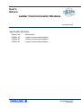
Applicable Modules:
Model Code
Model Name
F3RZ81-0F
F3RZ82-0F
Ladder Communication Module
Ladder Communication Module
F3RZ91-0F
Ladder Communication Module
IM 34M6H22-02E
Yokogawa Electric Corporation
2nd Edition
Blank Page
i
Applicable Product
z Range-free Multi-controller FA-M3
Model code
: F3RZ81-0F, F3RZ82-0F, F3RZ91-0F
Name
: Ladder Communication Module
The document number and document model code for this manual are given below.
Refer to the document number in all communications; also refer to the document
number and the document model code when purchasing additional copies of this
manual.
Document No.
:
IM 34M6H22-02E
Document Model Code
:
DOCIM
Media No. IM 34M6H22-02E (CD)
2nd Edition : Jan. 2008-00 (AR)
All Rights Reserved Copyright © 2008, Yokogawa Electric Corporation
IM 34M6H22-02E
2nd Edition : Jan. 30, 2008-00
ii
Important
About This Manual
-
This Manual should be passed on to the end user.
Before using the controller, read this manual thoroughly to have a clear
understanding of the controller.
This manual explains the functions of this product, but there is no guarantee that
they will suit the particular purpose of the user.
Under absolutely no circumstances may the contents of this manual be transcribed
or copied, in part or in whole, without permission.
The contents of this manual are subject to change without prior notice.
Every effort has been made to ensure accuracy in the preparation of this manual.
However, should any errors or omissions come to the attention of the user, please
contact the nearest Yokogawa Electric representative or sales office.
Safety Precautions when Using/Maintaining the Product
The following safety symbols are used on the product as well as in this manual.
Danger. This symbol on the product indicates that the operator must follow the
instructions laid out in this instruction manual to avoid the risk of personnel injuries,
fatalities, or damage to the instrument. Where indicated by this symbol, the manual
describes what special care the operator must exercise to prevent electrical shock
or other dangers that may result in injury or the loss of life.
Protective Ground Terminal. Before using the instrument, be sure to ground this
terminal.
Function Ground Terminal. Before using the instrument, be sure to ground this
terminal.
Alternating current. Indicates alternating current.
Direct current. Indicates direct current.
IM 34M6H22-02E
2nd Edition : Jan. 30, 2008-00
iii
The following symbols are used only in the instruction manual.
WARNING
Indicates a “Warning”.
Draws attention to information essential to prevent hardware damage, software
damage or system failure.
CAUTION
Indicates a “Caution”
Draws attention to information essential to the understanding of operation and
functions.
TIP
Indicates a “TIP”
Gives information that complements the present topic.
SEE ALSO
Indicates a “SEE ALSO” reference.
Identifies a source to which to refer.
-
For the protection and safe use of the product and the system controlled by it, be
sure to follow the instructions and precautions on safety stated in this manual
whenever handling the product. Take special note that if you handle the product in
a manner other than prescribed in these instructions, the protection feature of the
product may be damaged or impaired. In such cases, Yokogawa cannot guarantee
the quality, performance, function and safety of the product.
-
When installing protection and/or safety circuits such as lightning protection devices
and equipment for the product and control system as well as designing or installing
separate protection and/or safety circuits for fool-proof design and fail-safe design of
processes and lines using the product and the system controlled by it, the user
should implement it using devices and equipment, additional to this product.
-
If component parts or consumable are to be replaced, be sure to use parts specified
by the company.
This product is not designed or manufactured to be used in critical applications
which directly affect or threaten human lives and safety — such as nuclear power
equipment, devices using radioactivity, railway facilities, aviation equipment, air
navigation facilities, aviation facilities or medical equipment. If so used, it is the
user’s responsibility to include in the system additional equipment and devices that
ensure personnel safety.
-
-
Do not attempt to modify the product.
Exemption from Responsibility
-
Yokogawa Electric Corporation (hereinafter simply referred to as Yokogawa Electric)
makes no warranties regarding the product except those stated in the WARRANTY
that is provided separately.
-
Yokogawa Electric assumes no liability to any party for any loss or damage, direct or
indirect, caused by the use or any unpredictable defect of the product.
IM 34M6H22-02E
2nd Edition : Jan. 30, 2008-00
iv
Software Supplied by the Company
-
Yokogawa Electric makes no other warranties expressed or implied except as
provided in its warranty clause for software supplied by the company.
-
Use the software with one computer only. You must purchase another copy of the
software for use with each additional computer.
Copying the software for any purposes other than backup is strictly prohibited.
-
Store the original media, such as floppy disks, that contain the software in a safe
place.
-
Reverse engineering, such as decompiling of the software, is strictly prohibited.
No portion of the software supplied by Yokogawa Electric may be transferred,
exchanged, or sublet or leased for use by any third party without prior permission by
Yokogawa Electric.
IM 34M6H22-02E
2nd Edition : Jan. 30, 2008-00
v
General Requirements for Using the FA-M3 Controller
Avoid installing the FA-M3 controller in the following locations:
-
-
Where the instrument will be exposed to direct sunlight, or where the operating
temperature exceeds the range 0°C to 55°C (32°F to 131°F).
Where the relative humidity is outside the range 10 to 90%, or where sudden
temperature changes may occur and cause condensation.
Where corrosive or flammable gases are present.
-
Where the instrument will be exposed to direct mechanical vibration or shock.
Where the instrument may be exposed to extreme levels of radioactivity.
-
Use the correct types of wire for external wiring:
-
Use copper wire with temperature ratings greater than 75°C.
Securely tighten screws:
-
Securely tighten module mounting screws and terminal screws to avoid problems
such as faulty operation.
-
Tighten terminal block screws with the correct tightening torque as given in this
manual.
Securely lock connecting cables:
-
Securely lock the connectors of cables, and check them thoroughly before turning
on the power.
Interlock with emergency-stop circuitry using external relays:
-
Equipment incorporating the FA-M3 controller must be furnished with emergencystop circuitry that uses external relays. This circuitry should be set up to interlock
correctly with controller status (stop/run).
Ground for low impedance:
-
For safety reasons, connect the [FG] grounding terminal to a Japanese Industrial
Standards (JIS) Class D (earlier called Class 3) Ground*1 . For compliance to CE
Marking, use braided or other wires that can ensure low impedance even at high
frequencies for grounding.
*1 Japanese Industrial Standard (JIS) Class D Ground means grounding resistance of 100 Ω max.
Configure and route cables with noise control considerations:
-
Perform installation and wiring that segregates system parts that may likely become
noise sources and system parts that are susceptible to noise. Segregation can be
achieved by measures such as segregating by distance, installing a filter or
segregating the grounding system.
Configure for CE Marking Conformance:
-
For compliance to CE Marking, perform installation and cable routing according to
the description on compliance to CE Marking in the “Hardware Manual”
(IM34M6C11-01E).
IM 34M6H22-02E
2nd Edition : Jan. 30, 2008-00
vi
Keep spare parts on hand:
-
Stock up on maintenance parts including spare modules, in advance.
Discharge static electricity before operating the system:
-
Because static charge can accumulate in dry conditions, first touch grounded metal
to discharge any static electricity before touching the system.
Never use solvents such as paint thinner for cleaning:
-
Gently clean the surfaces of the FA-M3 controller with a cloth that has been soaked
in water or a neutral detergent and wringed.
-
Do not use volatile solvents such as benzine or paint thinner or chemicals for
cleaning, as they may cause deformity, discoloration, or malfunctioning.
Avoid storing the FA-M3 controller in places with high temperature or
humidity:
-
Since the CPU module has a built-in battery, avoid storage in places with high
temperature or humidity.
-
Since the service life of the battery is drastically reduced by exposure to high
temperatures, take special care (storage temperature should be from -20°C to
75°C).
-
There is a built-in lithium battery in a CPU module and temperature control module
which serves as backup power supply for programs, device information and
configuration information. The service life of this battery is more than 10 years in
standby mode at room temperature. Take note that the service life of the battery
may be shortened when installed or stored at locations of extreme low or high
temperatures. Therefore, we recommend that modules with built-in batteries be
stored at room temperature.
Always turn off the power before installing or removing modules:
-
Failing to turn off the power supply when installing or removing modules, may result
in damage.
Do not touch components in the module:
-
In some modules you can remove the right-side cover and install ROM packs or
change switch settings. While doing this, do not touch any components on the
printed-circuit board, otherwise components may be damaged and modules may fail
to work.
Do not use unused terminals:
-
Do not connect wires to unused terminals on a terminal block or in a connector.
Doing so may adversely affect the functions of the module.
IM 34M6H22-02E
2nd Edition : Jan. 30, 2008-00
vii
Waste Electrical and Electronic Equipment
Waste Electrical and Electronic Equipment (WEEE), Directive 2002/96/EC
(This directive is only valid in the EU.)
This product complies with the WEEE Directive (2002/96/EC) marking requirement.
The following marking indicates that you must not discard this electrical/electronic
product in domestic household waste.
Product Category
With reference to the equipment types in the WEEE directive Annex 1, this product is
classified as a “Monitoring and Control instrumentation” product.
Do not dispose in domestic household waste.
When disposing products in the EU, contact your local Yokogawa Europe B. V. office.
IM 34M6H22-02E
2nd Edition : Jan. 30, 2008-00
viii
Introduction
Overview of the Manual
This manual describes the specifications, operations, and communications protocol of
the ladder communication modules F3RZ81-0F, F3RZ82-0F, and F3RZ91-0F.
Related Instruction Manuals
Read the relevant manuals depending on the sequence CPU module type used:
For information on the functions of the F3SP66 or F3SP67 sequence
CPU modules, refer to:
-
Sequence CPU – Functions User's Manual (for F3SP66-4S, F3SP67-6S)
(IM34M6P14-01E)
-
Sequence CPU – Network Functions User's Manual (for F3SP66-4S, F3SP67-6S)
(IM34M6P14-02E)
For information on the functions of the F3SP28, F3SP38, F3SP53,
F3SP58, or F3SP59 sequence CPU modules, refer to:
-
Sequence CPU – Functions User' Manual (for F3SP28-3N/3S, F3SP38-6N/6S,
F3SP53-4H/4S, F3SP58-6H/6S, F3SP59-7S) (IM34M6P13-01E)
For information on the functions of the F3SP21, F3SP25, F3SP35,
F3SP05, or F3SP08 sequence CPU modules, refer to:
-
Sequence CPU – Functions User's Manual (for F3SP21, F3SP25, and F3SP35)
(IM34M6P12-02E)
For information on the instructions used with sequence CPUs, refer to:
-
Sequence CPU – Instructions User’s Manual (IM34M6P12-03E)
When creating programs using ladder language, refer to:
-
FA-M3 Programming Tool WideField2 User’s Manual (IM34M6Q15-01E)
For information on the specifications*, configuration*, installation,
wiring, trial operation, maintenance and inspection of the FA-M3, as
well as information on the system-wide limitation of module installation,
refer to:
*:
Hardware Manual (IM34M6C11-01E).
For information on the specifications of products other than the power supply module, base module, I/O module, cable
and terminal block unit, refer to their respective user’s manuals.
IM 34M6H22-02E
2nd Edition : Jan. 30, 2008-00
ix
Copyrights and Trademarks
Copyrights
Copyrights of the programs and online manual included in this CD-ROM belong to
Yokogawa Electric Corporation.
This online manual may be printed but PDF security settings have been made to prevent
alteration of its contents.
This online manual may only be printed and used for the sole purpose of operating this
product. When using a printed copy of the online manual, pay attention to possible
inconsistencies with the latest version of the online manual. Ensure that the edition
agrees with the latest CD-ROM version.
Copying, passing, selling or distribution (including transferring over computer networks)
of the contents of the online manual, in part or in whole, to any third party, is strictly
prohibited. Registering or recording onto videotapes and other media is also prohibited
without expressed permission of Yokogawa Electric Corporation.
Trademarks
-
The trade and company names that are referred to in this document are either
trademarks or registered trademarks of their respective companies.
IM 34M6H22-02E
2nd Edition : Jan. 30, 2008-00
Blank Page
TOC A-1
FA-M3
Ladder Communication Module
Part A: F3RZ81-0F/F3RZ82-0F
IM 34M6H22-02E 2nd Edition
CONTENTS
Applicable Product ....................................................................................i
Important ...................................................................................................ii
Introduction............................................................................................viii
Copyrights and Trademarks ...................................................................ix
Part A: F3RZ81-0F/F3RZ82-0F
A1. Overview .....................................................................................A1-1
A2. Specifications .............................................................................A2-1
A2.1
A2.2
A2.3
A2.4
Standard Specifications........................................................................A2-1
Model and Suffix Codes.....................................................................A2-1
Operating Environment ......................................................................A2-1
General Specifications .......................................................................A2-1
Physical Specifications.......................................................................A2-1
Function Specifications ......................................................................A2-1
Components and Functions ...............................................................A2-2
External Dimensions ..........................................................................A2-3
Switch Setup ..........................................................................................A2-4
Switches on the Module.....................................................................A2-4
External Wiring ......................................................................................A2-6
Connector Pin Assignment.................................................................A2-6
Directly Connecting to an RS-232-C Device, or DTE (data
terminal equipment) ...........................................................................A2-7
Connecting to a Modem, or DCE (data communications
equipment) .........................................................................................A2-8
Attaching/Detaching the Module..........................................................A2-9
A3. List of I/O Relays ........................................................................A3-1
A3.1
A3.2
Output Relays ........................................................................................A3-1
Input Relays ...........................................................................................A3-2
A4. List of Data Areas .......................................................................A4-1
A4.1
A4.2
Communications Mode Areas ..............................................................A4-2
Communications Mode Setup Area ...................................................A4-2
Communications Mode Status Area...................................................A4-3
Send and Receive Data Areas ..............................................................A4-6
A5. Startup Preparation ....................................................................A5-1
IM 34M6H22-02E
2nd Edition : Jan. 30, 2008-00
TOC A-2
A6. Data Communications................................................................A6-1
A6.1
A6.2
Format of Received Text.......................................................................A6-1
Break Signal...........................................................................................A6-3
A7. Programming ..............................................................................A7-1
A7.1
A7.2
A7.3
A7.4
Communications Mode Areas ..............................................................A7-1
Initializing Receive Buffer.....................................................................A7-4
Sending Data..........................................................................................A7-5
Receiving Data.......................................................................................A7-7
A8. Troubleshooting .........................................................................A8-1
A8.1
A8.2
A8.3
RDY LED is not Lit.................................................................................A8-2
Send Failure ...........................................................................................A8-3
Receive Failure ......................................................................................A8-4
Appendix A1. ASCII Code Table ............................................. Appx. A1-1
Index ........................................................................................... Index A-1
Revision Information .................................................................................i
IM 34M6H22-02E
2nd Edition : Jan. 30, 2008-00
A1-1
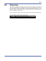
A1.
Overview
The Ladder Communication module can be used with an FA-M3 CPU module for
RS-232-C communications. The F3RZ81-0F has one and the F3RZ82-0F has two D-sub
9-pin connectors, or ports, which support a maximum transmission distance of 15 m.
Each port operates independently and a communications error at one port does not
affect the operation of the other port.
Any input relay of the Ladder Communication module may be used to raise an interrupt.
Table A1.1 Models of Ladder Communication Module
Model
F3RZ81-0F
F3RZ82-0F
Description
RS-232-C ladder communication module, one port
RS-232-C ladder communication module, two ports
IM 34M6H22-02E
2nd Edition : Jan. 30, 2008-00
Blank Page
A2-1
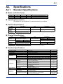
A2.
Specifications
A2.1
Standard Specifications
Model and Suffix Codes
Model
F3RZ81
F3RZ82
Suffix Code
-0F
-0F
Style Code
……
……
Option Code
Description
……
Max 115.2 kbps, one RS-232-C port
……
Max 115.2 kbps, two RS-232-C ports
Operating Environment
The F3RZ81-0F and F3RZ82-0F may be used with all CPU modules.
General Specifications
Item
Operating
temperature
Operating
humidity
Operating
environment
Specifications
Item
Specifications
0 to 55°C
Storage temperature
-20 to 75°C
10 to 90% RH (non-condensing)
Storage humidity
10 to 90% RH (non-condensing)
Must of free of corrosive gases,
flammable gases and heavy dust
Physical Specifications
Item
Specifications
Item
Specifications
320 mA
350 mA
Interface
EIA RS-232-C compliant
F3RZ81-0F
Current consumption
F3RZ82-0F
Number of ports
F3RZ81-0F
F3RZ82-0F
External dimensions
28.9 (W) x 100 (H) x 83.2 (D) mm*
Weight
F3RZ81-0F
F3RZ82-0F
Transmission
distance
Connector
1 (not isolated)
2 (not isolated)
15 m max.
120 g
120 g
D-Sub 9-pin (female), M2.6 (mm)
*: Dimensions excluding protrusions. For details, see the External Dimensions drawing.
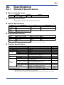
Function Specifications
Item
Connection method
Transmission mode
Synchronization
Communication protocol
Character length
Data format
Stop bits
Parity bit
Specifications
Point to point
Full-duplex/half-duplex
Start-stop synchronization
No protocol
7 or 8 bits
1 or 2 bits
None, even or odd
300, 600, 1200, 2400, 4800, 9600, 14400, 19200, 28800,
Transmission speed
38400, 57600, 76800, or 115200 bps
(1) Always on.
RS control
(2) Turn on before sending.
(1) Ignore DR when sending.
DR check
(2) Send only when DR is on.
Control lines
(1) Ignore CD when sending.
CD check
(2) Send only when CD is off.
(1) On (ready)
ER control
(2) Off (not ready)
Communication
Send buffer
Text buffer (3584 bytes max.)*3
buffer
Receive buffer
8192-byte rotary buffer (FIFO buffer)
- Yes or no
Start character
- Any single character
Format of
Yes or no
received text
End character (terminator) - Up to 2 characters long, any characters
- Also used as send terminator.
IM 34M6H22-02E
Default
―
―
―
―
*1 (see next page)
*1 (see next page)
*1 (see next page)
*2
(1)
(1)
(1)
(1)
―
―
No
$0D and $0A
(CR-LF)
2nd Edition : Jan. 30, 2008-00
A2-2
Item
Text length
Character-to-character
timeuot interval
Format of
received text
Clear-to-send timeout interval
Break transmission interval
Specifications
Can be specified as any number between 1 and 3584*3.
0 to 32760 ms in 1 ms increments,
accurate to 1 ms (0 means not monitored)
0 to 32760 ms in 1 ms increments,
accurate to 1 ms (0 means not monitored)
1 to 32760 ms in 1 ms increments, accurate to 1 ms
Default
1024
1.5 s
Monitored
(30 s)
400 ms
*1: Default values are set with the data format switch (SW2).
*2: Default values are set with the transmission speed switch (SW1).
*3: The send/receive data register size can be changed to accommodate up to 3584 bytes.
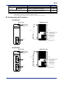
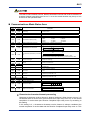
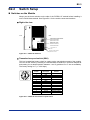
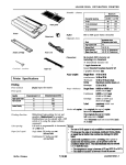
Components and Functions
z F3RZ81-0F
Front view
Indicator RDY:
RDY
RZ81-0F
Right side view
RS232C
Lit when the internal
circuit is functioning
normally.
Front
Rear
SW1
Transmission speed switch
SW3
O
F
F
1
1
2
3
4
5
6
7
8
SW2
O
F
F
1
2
3
4
5
6
7
8
Sets the transmission
speed of the module.
Data format switch
Defines the format of
communication data.
This switch is not used.
Port 1
This figure is drawn with the
panel cover removed.
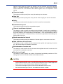
z F3RZ82-0F
Front view
Indicator RDY:
RDY
RZ82-0F
Right side view
RS232C
Lit when the internal
circuit is functioning
normally.
1
Front
Rear
SW1
Port 1
Transmission speed switch
SW3
O
F
F
2
1
2
3
4
5
6
7
8
SW2
O
F
F
1
2
3
4
5
6
7
8
Sets the transmission
speed of the module.
Data format switch
Defines the format of
communication data.
This switch is not used.
Port 2
This figure is drawn with the
panel cover removed.
IM 34M6H22-02E
2nd Edition : Jan. 30, 2008-00
A2-3
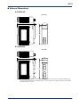
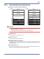
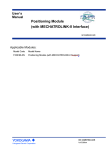
External Dimensions
z F3RZ81-0F
(Unit: mm)
83.2
6.7
28.9
2
100
z F3RZ82-0F
(Unit: mm)
83.2
6.7
28.9
2
100
Note: This module requires a minimal mounting depth of 173 (83 + 90) mm so that it can be comfortably installed on the
base module and attached with an external RS-232-C connector and cable, with adequate space to accommodate
the bending radius of the cable.
IM 34M6H22-02E
2nd Edition : Jan. 30, 2008-00
A2-4
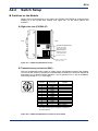
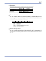
A2.2
Switch Setup
Switches on the Module
Always set the three switches on the side of the F3RZ81-0F/F3RZ82-0F module before
installing it on the FA-M3 base module. See Figure A2.1 for the switch names and
locations.
z Right side view (F3RZ82-0F)
Front
Rear
SW1
Transmission speed switch
SW3
O
F
F
1
2
3
4
5
6
7
8
Sets the transmission
speed of the module.
SW2
O
F
F
1
2
3
4
5
6
7
8
Data format switch
Defines the format of
communication data.
This switch is not used.
This figure is drawn with the
panel cover removed.
Figure A2.1 F3RZ81-0F/F3RZ82-0F Switches
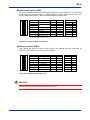
z Transmission speed switch (SW1)
This is a hexadecimal rotary switch for setting up the transmission speed of the module.
You can set the switch by inserting a small flat-blade screwdriver in its arrow-shaped slit
and rotating it to a desired position between 1 and C (positions D to F are not available).
The factory setting is ‘C’ (= 115.2 kbps).
SW1
Position
0
1
2
3
4
5
6
7
8
9
A
B
C
D-F
Transmission
speed (bps)
300
600
1200
2400
4800
9600
14400
19200
22800
38400
57.6K
76.8K
115.2K
------
Remarks
Factory setting
Not available
- The setting with SW1 applies to both port 1 and port 2.
- The SW1 setting may be changed by software for
an individual port.
Figure A2.2 F3RZ81-0F/F3RZ82-0F Transmission speed Switch
IM 34M6H22-02E
2nd Edition : Jan. 30, 2008-00
A2-5
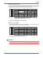
z Data format switch (SW2)
This is an 8-element DIP switch for defining a character frame. Elements 1-4 may be set
to either the ON or OFF position to define character length, parity and stop bits. The
factory setting has element 1 set to ON and elements 2-8 set to OFF.
O
F
F
1
2
3
4
5
6
7
8
SW2 Elements
1
2
3
4
5
6
7
8
Function
Character length
Parity
Stop bits
Not used
Not used
Not used
Not used
OFF
7 bits
No
Odd
1 bit
-------------
ON
8 bits
Yes
Even
2 bits
-------------
Default
8 bits
No parity
---1 bit
-------------
ON
OFF
OFF
OFF
OFF
OFF
OFF
OFF
- The SW2 setting applies to both port 1 and port 2.
- The SW2 setting may be changed by software for an individual port.
- SW2-3 is available only when SW2-2 is set to ON (= using parity).
- Always set SW2-5 to SW2-8 to OFF.
Figure A2.3 F3RZ81-0F/F3RZ82-0F Data Format Switch
z Reserved switch (SW3)
The F3RZ81-0F/F3RZ82-0F does not use the SW3 switch. The module must be used
with all elements of this switch set to OFF (factory setting).
O
F
F
1
2
3
4
5
6
7
8
SW3 Elements
1
2
3
4
5
6
7
8
Function
Not used
Not used
Not used
Not used
Not used
Not used
Not used
Not used
OFF
ON
Default
OFF
OFF
OFF
OFF
OFF
OFF
OFF
OFF
Figure A2.4 F3RZ81-0F/F3RZ82-0F Reserved Switch
CAUTION
Ensure that all unused switch elements are set to OFF.
IM 34M6H22-02E
2nd Edition : Jan. 30, 2008-00
A2-6
A2.3
External Wiring
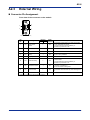
Connector Pin Assignment
Front view of the connector on the module
5
9
6
1
9-pin D-sub connector (female)
Pin
No.
Symbol
Signal
Direction
Signal
FA-M3 Remote Monitored
1
CD
Data carrier
detect
2
RD
Receive data
←
No
3
SD
Send data
→
No
4
ER
Data terminal
ready
→
No
5
SG
Signal ground
←→
No
←
Yes
6
DR
Data set ready
←
Yes
7
RS
Request to send
→
No
8
CS
Clear to send
←
Yes
9
—
Not used
—
No
Description
The module receives data only when this signal is
on and sends data as follows:
(1) Ignore CD when sending (default), or
(2) Send only when CD is off.
(1) On when powered (default), or
(2) On or off by software.
Used to check whether the remote station is ready
to receive data.
(1) Ignore DR when sending (default), or
(2) Send only when DR is on.
Used when sending data to the remote station.
(1) Always on (default), or
(2) Turn on before sending data.
Clear-to-send signal from a remote device.
The module can send data only when this signal is
on.
*: Option (1) or (2) can be selected using a program.
IM 34M6H22-02E
2nd Edition : Jan. 30, 2008-00
A2-7
Directly Connecting to an RS-232-C Device, or DTE (data terminal
equipment)
Null modem cable
Null modem cable
Shield
Connector
cover
F3RZ82-0F
(9-pin D-sub
connector)
Connector
cover
Connector
cover
1(FG)
(SD)3
2(SD)
(RD)2
3(RD)
(RS)7
4(RS) Remote
(CS)8
5(CS)
F3RZ82-0F
DTE
(9-pin D-sub
connector)
Shield
Connector
cover
(SD)3
3(SD)
(RD)2
2(RD)
(RS)7
7(RS)
(CS)8
8(CS) Remote
DTE
(DR)6
(DR)6
(25-pin D-sub
6(DR) connector)
(SG)5
6(DR) (9-pin D-sub
5(SG) connector)
(SG)5
7(SG)
(CD)1
1(CD)
(CD)1
8(CD)
(ER)4
4(ER)
(ER)4
20(ER)
*: Pin numbers of the connector of the remote DTE shown in
this diagram assumes a 25-pin D-sub connector. An
example of such a cable is YOKOGAWA's YCB cable.
Figure A2.5 Wiring to 25-pin D-sub Connector
Figure A2.6 Wiring to 9-pin D-sub Connector
z How to treat the shield
1. Ensure that the connector for the connection cable has a metal or metal-clad cover.
Connect the shield directly to the cover.
2. The connector shell of the F3RZ81-0F/F3RZ82-0F is internally connected to the
Frame Ground terminal (FG) of the FA-M3 power supply module.
z Recommended connection cable
YOKOGAWA's null-modem cable is recommended for this purpose.
Model Name
Suffix Code
Description
RS-232-C null-modem cable with control lines between 9-pin
connector (on CP7 ML gateway card) and 25-pin
connector (on RS-232-C equipment)
YCB215
-KM01
-KM05
-KM15
1 m cable
5 m cable
15 m cable
Note: This cable is for indoor use only. The wires are termination-treated.
z Internal connection diagram for YCB215 cable
YCB215 CN1 side (FA-M3)
PIN No.
CN2 side
PIN No.
Shield
Connector cover
FG
Connector cover
1
SD
SD
RD
RD
RS
RS
4
CS
CS
5
DR
DR
6
SG
SG
1
CD
CD
4
ER
ER
3
2
7
8
6
5
2
3
7
8
20
IM 34M6H22-02E
2nd Edition : Jan. 30, 2008-00
A2-8
Connecting to a Modem, or DCE (data communications equipment)
Null modem cable
Modem cable
Connector
cover
Connector
cover
(SD)3
3(SD)
(SD)3
3(SD)
(RD)2
2(RD)
(RD)2
2(RD)
(RS)7
7(RS)
(RS)7
7(RS)
8(CS) Remote
F3RZ82-0F (CS)8
(9-pin D-sub
connector)
Connector
cover
Connector
cover
F3RZ82-0F (CS)8
DCE
(DR)6
(9-pin D-sub
connector)
8(CS)
Remote
DCE
(SG)5
6(DR) (25-pin D-sub
5(SG) connector)
(SG)5
6(DR) (9-pin D-sub
5(SG) connector)
(CD)1
1(CD)
(CD)1
1(CD)
(ER)4
4(ER)
(ER)4
4(ER)
(DR)6
*: Pin numbers of the connector of the remote DCE shown in
this diagram assumes a 25-pin D-sub connector. An
example of such a cable is YOKOGAWA's YCB211 cable.
Figure A2.7 Wiring to 25-pin D-sub Connector
Figure A2.8 Wiring to 9-pin D-sub Connector
z How to treat the shield
1. Ensure that the connector for the connection cable has a metal or metal-clad cover.
Connect the shield directly to the cover.
2. The connector shell of the F3RZ81-0F/F3RZ82-0F is internally connected to the
Frame Ground terminal (FG) of the FA-M3 power supply module.
z Recommended connection cable
YOKOGAWA's modem cable is recommended for this purpose
Model Name
Suffix Code
Description
RS-232-C modem cable between 9-pin connector
(on CP7 ML gateway card) and 25-pin connector
(on modem)
YCB211
-KM01
-KM05
-KM15
1-m cable
5-m cable
15-m cable
Note: This cable is for indoor use only. The wires are termination-treated.
z Internal connection diagram for YCB211 cable
YCB211 CN1 side (FA-M3)
PIN No.
Connector cover
Shield
Connector cover
FG
1
SD
SD
RD
RD
RS
RS
CS
CS
DR
DR
SG
SG
CD
CD
ER
ER
CI
CI
3
2
2
3
7
4
8
5
6
6
5
7
1
8
4
9
20
22
IM 34M6H22-02E
2nd Edition : Jan. 30, 2008-00
A2-9
A2.4
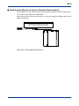
Attaching/Detaching the Module
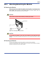
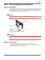
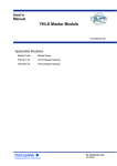
Attaching the Module
Figure A2.9 shows how to attach this module to the base module. First hook the anchor
slot at the bottom of the module to be attached onto the anchor pin on the bottom of the
base module. Push the top of the module toward the base module until the
anchor/release button (yellow button) clicks into place.
CAUTION
Always switch off the power before attaching or detaching the module.
Base Module
Anchor
pin
Ladder
Communication
Module
F01.VSD
Figure A2.9 Attaching/Detaching the Module
CAUTION
Do not bend the connector on the rear of the module by force during the above
operation. If the module is pushed with improper force, the connector may bend, causing
an error.
Detaching the Module
To remove this module from the base module, reverse the above operation.
Press the anchor/release button (yellow button) on the top of this module to unlock it
and tilt the module away from the base module.
IM 34M6H22-02E
2nd Edition : Jan. 30, 2008-00
A2-10
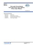
Attaching the Module in Intense Vibration Environments
If the module is used in intense vibration environments, fasten the module with a screw.
Use screws of type listed in the table below.
Insert these screws into the screw holes on top of the module and tighten them with a
Phillips screwdriver.
Screw Required
M4-size binder screw 12 to 15 mm long
(or 14-15 mm long if fitted with a washer)
F02R1.VSD
Figure A2.10 Securing Module Using Screws
IM 34M6H22-02E
2nd Edition : Jan. 30, 2008-00
A3-1
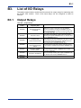
A3.
List of I/O Relays
The ladder communication module has 32 input and 32 output relays for interfacing with
the FA-M3 CPU module. Each of the input relays can be configured to raise an
interrupt.
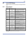
A3.1
Output Relays
Table A3.1 Output Relays
Output Relay
Number
Y33
Read Received Data
Completed*1
Y34
Request to Send*1
Y35
Request to Set
Communications Mode*1
Y36
Request to Read
Communications Mode
Status*1
Y37
Request to Initialize
Receive Buffer*1
Y38
Request to Send Break*1
Y39 to
Y48
Turn on this relay after reading data from the receive
data area. Turning on this relay turns off X01
(receive completed normally) and X07 (receive
error), and the module is ready to receive new data into
the receive data area.
Turn on this relay after having stored send data size and
send data to the registers. If data is sent successfully
following this request, X02 turns on, and if an error
occurs, X08 turns on.
Turn on this relay after having stored communications
mode setting in the communications mode area. If setup
is successful following this request, X03 turns on,
and if an error occurs, X09 turns on.
Turn on this relay to read the contents of the
communications mode area and the control line status. If
the request is completed successfully, X04 turns
on.
Turn on this relay to initialize the receive buffer and the
communications controller. X05 turns on after
successful initialization.
Turn on this relay to send a break signal. If a break is
sent successfully following this request, X06 turns
on, and if an error occurs, X08 turns on.
Reserved
Y49
Read Received Data
Completed*2
Y50
Request to Send*2
Y51
Request to Set
Communications Mode*2
Y52
Request to Read
Communications Mode
Status*2
Y53
Request to Initialize
Receive Buffer*2
Y54
Request to Send Break*2
Y55 to
Y64
Description
Output Relay Name
Turn on this relay after having read all data from the
receive data area. Turning on this relay turns off
X17 (receive completed normally) and X23
(receive error), and the module is ready to receive new
data in the receive data area.
Turn on this relay after having stored send data size and
send data to the registers. If data is sent successfully
following this request, X18 turns on, and if an error
occurs, X24 turns on.
Turn on this relay after having stored communications
mode setting in the communications mode area. If setup
is successful following this request, X19 turns on,
and if an error occurs, X25 turns on.
Turn on this relay to read the contents of the
communications mode area and the control line status. If
the request is completed successfully, X20 is turns
on.
Turn on this relay to initialize the receive buffer and the
communications controller. X21 turns on after
successful initialization.
Turn on this relay to send a break signal. If a break is
sent successfully following this request, X22 turns
on, and if an error occurs, X24 turns on.
Reserved
*1
: Applies to F3RZ81-0F or port 1 of F3RZ82-0F.
*2
: Applies to port 2 of F3RZ82-0F only. Reserved for system use in F3RZ81-0F.
: Slot number
IM 34M6H22-02E
2nd Edition : Jan. 30, 2008-00
A3-2
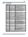
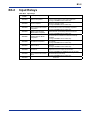
A3.2
Input Relays
Table A3.2 Input Relays
Input Relay
Number
X01
Receive Completed*1
X02
Send Completed*1
X03
Set Communications Mode
Completed*1
X04
Read Communications
Mode Status Completed*1
X05
Initialize Receive Buffer
Completed*1
X06
Send Break Completed*1
X07
Receive Error*1
X08
Send Error*1
X09
Set Communications Mode
Error*1
X10 to
X16
This relay turns on when received data is transferred
from the receive buffer to the receive data area.
Turning on Y33 turns off this relay.
This relay turns on when data is successfully sent
following a request to send.
Turning off Y34 turns off this relay.
This relay turns on when a request to set
communications mode is successfully completed.
Turning off Y35 turns off this relay.
This relay turns on when the communications mode
status has been successfully read out and stored.
Turning off Y36 turns off this relay.
This relay turns on when the receive buffer and the
communications controller have been successfully
initialized.
Turning off Y37 turns off this relay.
This relay turns on when a break signal has been sent
successfully.
Turning off Y38 turns off this relay.
This relay turns on if error is detected during data
receiving.
Turning on Y33 turns off this relay.
This relay turns on if error is detected when processing a
request to send or a request to send break.
Turning off Y34 or Y38 turns off this relay.
This relay turns on if error is detected during
communications mode setup.
Turning off Y35 turns off this relay.
Reserved
X17
Receive Completed*2
X18
Send Completed*2
X19
Set Communications Mode
Completed*2
X20
Read Communications
Mode Status Completed*2
X21
Initialize Receive Buffer
Completed*2
X22
Send Break Completed*2
X23
Receive Error*2
X24
Send Error*2
X25
Set Communications Mode
Error*2
X26 to
X32
Description
Input Relay Name
This relay turns on when received data is transferred
from the receive buffer to the receive data area.
Turning on Y49 turns off this relay.
This relay turns on when data is successfully sent
following a request to send.
Turning off Y50 turns off this relay.
This relay turns on when a request to set
communications mode is successfully completed.
Turning off Y51 turns off this relay.
This relay turns on when the communications mode
status has been successfully read out and stored.
Turning off Y52 turns off this relay.
This relay turns on when the receive buffer and the
communications controller have been successfully
initialized.
Turning off Y53 turns off this relay.
This relay turns on when a break signal has been sent
successfully.
Turning off Y54 turns off this relay.
This relay turns on if error is detected during data
receiving.
Turning on Y49 turns off this relay.
This relay turns on if error is detected when processing a
request to send or a request to send break.
Turning off Y50 or Y54 turns off this relay.
This relay turns on if error is detected during
communications mode setup.
Turning off Y51 turns off this relay.
Reserved
*1
: Applies to F3RZ81-0F or port 1 of F3RZ82-0F.
*2
: Applies to port 2 of F3RZ82 only. Reserved for system use in F3RZ81-0F.
: Slot number
IM 34M6H22-02E
2nd Edition : Jan. 30, 2008-00
A4-1
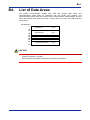
A4.
List of Data Areas
The ladder communication module has send and receive data areas and
communications mode areas for interfacing with the FA-M3 CPU module. The
communications mode areas are used to store communications mode settings, and the
send and receive data areas are used to store data to be sent and data received
respectively.
Data
Position No.
Data
Position No.
F3RZ81-0F
1
1
Send data area
(port 1)
384
385
Receive data area
(port 1)
(port 1)
Receive data area
(port 1)
Send data area
(port 2)
Receive data area
(port 2)
Send data byte count
Send status
Receive data status
Receive data byte count
Send data byte count
Send status (part 2)
Receive data status
Receive data byte count
(port 1)
(port 1)
(port 1)
(port 1)
(port 2)
Communications mode area
(port 1)
Communications mode area
(port 2)
896
897
Extended send/receive data area
Send data byte count
Send status
Receive data status
Receive data byte count
Reserved
Reserved
Reserved
Reserved
(port 1)
(port 1)
(port 1)
(port 1)
Communications mode area
(port 1)
1920
1921
1280
1281
1792
1793
1794
1795
1796
1797
1798
1799
1800
1857
(port 2)
(port 2)
1920
1921
Reserved
1984
Send data area
384
385
896
897
1792
1793
1794
1795
1796
1797
1798
1799
1800
1857
F3RZ82-0F
1984
CAUTION
-
You may customize the send data area size and receive data area size to use data
positions between 1 and 1792.
-
Data positions above 1792 are fixed and cannot be customized.
IM 34M6H22-02E
2nd Edition : Jan. 30, 2008-00
A4-2
A4.1
Communications Mode Areas
Data Position No.
1857
1888
1889
1920
1921
1952
1953
1984
Setup area
Communications mode area
(port 1)
Status area
Setup area
Communications mode area
(port 2)*
Status area
* Reserved area for F3RZ81-0F.
Each communications mode area is divided into two sub-areas: setup area and status
area. A user program writes communications mode settings to the setup area before
issuing a request to set communications mode. It reads the status area to check the
internal communications mode parameters of the module.
Communications Mode Setup Area
Data Position No
Port 1
Port 2*4
1857
1921
1858
1859
1860
1922
1923
1924
1861
1925
1862
1863
1926
1927
1864
1928
Description*2
Character-to-character timeout
0: receive successful; 1: receive error
processing
Character length
0: 7 bits; 1: 8 bits
Stop bits
0: 1 bit; 1: 2 bits
Parity
0: none; 1: odd; 2: even
0: 300
4: 4800
8: 28800
12: 115200
1: 600
5: 9600
9: 38400
Transmission speed (in bps)
2: 1200
6: 14400
10: 57600
3: 2400
7: 19200
11: 76800
Clear-to-send timeout interval 0 to 32760 (ms); 0 means not monitored
Break transmission interval
1 to 32760 (ms)
15
8 7
0
Start character of receive text
0
Start character
- All 0's if no start character is used
15
8 7
0
First terminator
1929
1866
1930
1867
1931
1868
1869
1932
1933
Reserved
1870
1934
RS control
1871
1935
ER control
1872
1936
DR check
CD check
1873
1937
1938 to
1950
1951
1888
1952
Second terminator
End character (terminator) of
receive text
1865
1874 to
1886
1887
Default
- All 0's for the first terminator if only one end character is
used.
- All 0's for the first and second terminators if no end
character is used.
0 to 1024 (number of characters on the line)*3
Receive text length
0 means no receiving.
Character-to-character timeout 0 to 32760 (ms)
interval
0 means not monitored
0: Always On
1: Turn on before sending
0: Off
1: On
0: Ignore DR when sending
1: Send only when DR is on
0: Ignore CD when sending
1: Send only when CD is off
0
*1
*1
*1
*2
30000 (= 30s)
400
0
$0D $0A
(CR LF)
1024
1500
0
1
0
0
Reserved
Send data area size
Receive data area size
- In units of words
- Total size for send and receive data areas must not
exceed 1792 words (3584 bytes)
384
512
*1: The default value is set with the SW2 switch.
*2: The default value is set with the SW1 switch.
*3: Depends on receive data area size.
*4: Reserved area for F3RZ81-0F.
IM 34M6H22-02E
2nd Edition : Jan. 30, 2008-00
A4-3
The clear-to-send timeout interval, break transmission interval and receive character-tocharacter timeout interval have an error of 1 ms so the actual duration may be up to1 ms
shorter than the specified value.
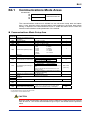
Communications Mode Status Area
Data Position No
Port 1
Port 2*
Description
Character-to-character timeout
processing
Character length
Stop bits
Parity
0: receive successful
1: receive error
0: 7 bits; 1: 8 bits
0: 1 bit; 1: 2 bits
0: none; 1: odd; 2: even
0: 300
4: 4800
8: 28800
12: 115200
1: 600
5: 9600
9: 38400
Transmission speed (in bps)
2: 1200
6: 14400
10: 57600
3: 2400
7: 19200
11: 76800
Clear-to-send timeout interval
0 to 32760 (ms); 0 means not monitored
Break transmission interval
1 to 32760 (ms)
1
5
8 7
0
Start character of receive text
0
Start character
・ All 0's if no start character is used
1
5
87
0
End character (terminator) of receive
First terminator
Second terminator
text
All 0's for the first terminator if only one end character is used
All 0's for the first and second terminators if no end character is used
0 to 1024 (number of characters on the line)*3
Receive text length
0 means no receiving
Character-to-character timeout
0 to 32760 (ms);
interval
0 means not monitored
1889
1953
1890
1891
1892
1954
1955
1956
1893
1957
1894
1895
1958
1959
1896
1960
1897
1961
1898
1962
1899
1963
1900
1901
1964
1965
Reserved
1902
1966
RS control
1903
1967
ER control
1904
1968
DR check
1905
1969
CD check
0: Always On
1: Turn on before sending
0: Off
1: On
0: Ignore DR when sending
1: Send only when DR is on
0: Ignore CD when sending
1: Send only when CD is off
1906-1916 1970-1980 Reserved
1917
1981
Send data area size
1918
1982
Receive data area size
15
1919
1983
Control line status
1920
1984
Setup error information
5
0
15
4
R
S
3
E
R
2
C
S
8 7
Data position no.
1
D
R
0
C
D
0
* Reserved area for F3RZ81-0F.
z Character-to-character timeout processing
Character-to-character receive timeout is always monitored. When timeout occurs, it is
considered either a receive error (the Receive Error input relay turns on) or the normal
completion of receive data (the Receive Completed input relay turns on) according to
this setting.
If this setting is 0, a character-to-character receive timeout is always considered the
normal completion of receive data and the Receive Completed input relay turns on. This
IM 34M6H22-02E
2nd Edition : Jan. 30, 2008-00
A4-4
setting is useful when the receive text length or the end character cannot be specified.
When a character-to-character receive timeout occurs, the character-to-character
receive timeout bit of the Receive data Status register turns on irrespective of this
setting.
z Character length
This setting is used to specify how many bits make up one character.
z Stop bits
This setting is used to specify how many bits are used to signify the end of a character.
z Parity
This setting is used to define the parity bit, which is used for error detection.
z Transmission speed
This setting is used to specify the transmission speed.
z Clear-to-send timeout interval
This setting is used to specify the maximum time allowed for starting and completing a
transmission before timeout occurs. Sending cannot start if the send condition specified
by the DR Check or CD Check setting is not satisfied, or if the communications cable is
loose or not connected. If a timeout occurs, a send error is generated. If this setting is 0,
timeout will never occur.
z Break transmission interval
This setting is used to specify the duration of a break signal. It cannot be set to 0 ms.
z Start character of receive text
This setting is used to define the start character that signifies the beginning of receive
text. No start character is attached to send text.
z End character of receive text
This setting is used to define the end character that signifies the end of receive text. No
end character is attached to send text.
z Receive text length
This setting is used to specify the number of characters for delimiting receive text. This
setting may not exceed a user-defined receive data area size.
CAUTION
-
If the receive text length is set to a value larger than the receive data area size, the
receive data area size is used. If the receive text length is set to a value larger than
3584, however, a Set Communications Mode Error is generated.
-
The receive text length is ignored if the receive data area size is set to 0.
If the receive text length is set to 0, the module can receive no data.
IM 34M6H22-02E
2nd Edition : Jan. 30, 2008-00
A4-5
z Character-to-character timeout interval
This setting is used to define the character-to-character receive timeout interval, which is
the maximum allowable lapse between two successive characters in the same text.
When a timeout occurs, whether it is considered a receive error or the normal
completion of receive text depends on the character-to-character timeout processing
setting.
z RS (Request to Send) control
The RS control signal is used to notify remote data equipment that the module has data
to send.
This setting is used to specify whether the module should always turn on the RS signal
or should turn on the RS signal only when it has data to send.
z ER (Data Terminal Ready) control
The ER control signal is used to notify remote data equipment that the module is ready
to receive data. This control signal can be turned on or turned off by a user program.
z DR (Data Set Ready) check
When connecting the module to remote DTE (data terminal equipment), the DR terminal
of the module is normally connected to the ER terminal of the remote DTE to monitor
whether the remote DTE is ready to receive data from the module.
This setting is used to specify whether the module should check that the DR signal is on
before sending data.
z CD (Data Carrier Detect) check
When connecting the module to remote DTE (data terminal equipment), the CD terminal
of the module is normally connected to the RS terminal of the remote DTE to monitor
whether the remote DTE has data to send.
This setting is used to specify whether the module should check that the CD signal is off
before sending data.
z Control line status
A user program may read the control line status to monitor the status of each control
signal.
z Send data area size, receive data area size
Use these settings to specify the size of the send and receive data areas respectively.
A total space of 1792 words (3584 bytes) may be freely shared among the send and
receive data areas. If a send or receive data area size is set to 0, however, that area is
disabled and the related function is no longer available.
CAUTION
-
If the send data area size of a port is set to 0, the send error is generated when the
request to send is issued for that port.
-
If the receive data area size of a port is set to 0, it will not be available for receiving.
Do not change the setting of the send data area size or the receive data area size
during communication.
-
If the setting of the send or receive data area size is changed during
communication, beware that there may be old data remaining in the data areas.
IM 34M6H22-02E
2nd Edition : Jan. 30, 2008-00
A4-6
A4.2
Send and Receive Data Areas
z Allocation of send and receive data areas
Data
Position No.
1
384
385
896
897
Data
Position No.
F3RZ81-0F
Send data area
(port 1)
(768 bytes)
Receive data area
(1024 bytes)
(port 1)
Send data byte count
Send status
Receive data status
Receive data byte count
Reserved
Reserved
Reserved
Reserved
384
385
896
897
Extended send/receive data area
1792
1793
1794
1795
1796
1797
1798
1799
1800
1
(port 1)
(port 1)
(port 1)
(port 1)
1280
1281
1792
1793
1794
1795
1796
1797
1798
1799
1800
F3RZ82-0F
Send data area
(port 1)
(768 bytes)
Receive data area
(1024 bytes)
(port 1)
Send data area
(port 2)
(768 bytes)
Receive data area
(1024 bytes)
(port 2)
Send data byte count
Send status
Receive data status
Receive data byte count
Send data byte count
Send status
Receive data status
Receive data byte count
(port 1)
(port 1)
(port 1)
(port 1)
(port 2)
(port 2)
(port 2)
(port 2)
CAUTION
-
You may customize the send data area size and receive data area size for using
data positions between 1 and 1792.
Data positions above 1792 are fixed and cannot be customized.
z Send data area
This area is used to store data to be sent.
z Receive data area
This area is used to store data received.
z Extended send/receive data area
For F3RZ81-0F, this is extra data space, which can be used by modifying the send data
area size and/or the receive data area size from their respective default setting values of
384 and 512 words.
z Send data byte count
This area is used to store the number of bytes to be sent. Following a request to send,
data is sent until the specified number of bytes is reached.
IM 34M6H22-02E
2nd Edition : Jan. 30, 2008-00
A4-7
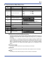
z Send status
This area is used to store the completion status after transmission.
Status
Error Code
(Decimal)
0000
0100
0201
0202
0203
Send successful
Send data size error
Send timeout
Description
Cable connection failure
DR check error
CD check error
z Receive data status
This area stores the status of the received text stored in the receive data area. The
status is a combination of error bits (see the table below). An error bit is turned on if the
corresponding error is detected for any byte of the received text. If an error bit is turned
on, there is no way to tell which byte is the cause.
15 to 06
Reserved
05
ORER
ORER
FER
PER
IBOF
RCTO
BREAK
04
FER
03
PER
02
IBOF
01
RCTO
00
BREAK
: Overrun error
: Framing error
: Parity error
: Receive buffer overflow
: Character-to-character receive timeout
: Break signal received
z Receive data byte count
This area stores the number of bytes of data received. By reading the value stored in
this area, a program can determine the size of received data. The end character in
received data is automatically deleted when the received data is stored in the receive
data area.
IM 34M6H22-02E
2nd Edition : Jan. 30, 2008-00
Blank Page
A5-1
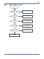
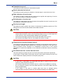
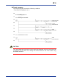
A5.
Startup Preparation
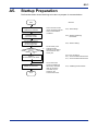
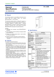
The flowchart below shows the things to be done to prepare for communications.
Start
See Also:
Set up communications
conditions by hardware.
Set the module and the
remote equipment with the
same communications
conditions.
Install the module
on the base module.
A2.4, "Attaching/detaching
the Module"
Connect the module to
equipment through a
communications line.
Writing to
communications mode areas
necessary?
Yes
A2.3, "External Wiring"
No
Not necessary if the
settings with the
switches on the side of
the module are used
as they are.
A3, "List of I/O Relays"
A4.1, "Communications Mode Areas"
A7.1, "Communications Mode Areas"
Write to
communication mode areas.
Initialize receive buffer.
End
A2.2, "Swtich Setup"
The receive buffer
should be initialized to
discard any unwanted
data due to electric
noise that may be
present on the
communications line.
A7.2, "Initializing Receive Buffer"
IM 34M6H22-02E
2nd Edition : Jan. 30, 2008-00
Blank Page
A6-1
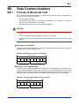
A6.
Data Communications
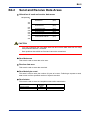
A6.1
Format of Received Text
The F3RZ81-0F/F3RZ82-0F ladder communication module may recognize a block of
received text by any of the following three means:
- By receiving a terminator
-
By receiving the number of characters designated by the Receive Text Length
setting in the communications mode area
-
By detecting a character-to-character receive timeout
CAUTION
-
A block of received text is recognized when any of the above three conditions is
met.
-
You may explicitly disable individual conditions if so desired.
However, you may not disable the condition defined by the Receive Text Length
setting.
IM 34M6H22-02E
2nd Edition : Jan. 30, 2008-00
A6-2
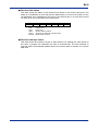
z Receiving a terminator
A block of text is recognized when a terminator (end characters) is received. The default
terminator is the CR-LF character pair.
Example: If ETX ($03) is used as a terminator
Receive data
A
B
C
ETX
D
E
Received text 1
F
G
ETX
Received text 2
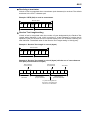
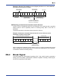
z Receive Text Length setting
A block of text is recognized when the number of bytes designated by the Receive Text
Length setting (between 1 and 1024) is received. If a start character of receive text is
specified, bytes for received text are counted starting from the character following the
start character. The default value for the Receive Text Length setting is 1024 (bytes).
Example 1: Receive Text Length is set to 4 (bytes)
Receive data
A
B
C
D
E
Received text 1
F
G
H
Received text 2
Example 2: Receive Text Length is set to 6 (bytes) with the use of start character
STX ($02) and terminator ETX ($03)
Start character
of received text
Start character
of received text
A
B
STX
Discarded
P
Q
R
S
T
Received text 1
(6 bytes received)
U
STX
E
Terminator
N
D
ETX
Received text 2
(terminator detected)
Any data arriving after the
end of text 1 and before the
start of text 2 is discarded.
IM 34M6H22-02E
2nd Edition : Jan. 30, 2008-00
A6-3
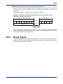
z Detecting a character-to-character receive timeout
A block of text is recognized when the next character is not received after a specified
timeout interval. This is especially useful for receiving binary data or text with no
terminator.
The default character-to-character timeout interval is 1500 ms
Example: Character-to-character timeout interval is set to 1000 ms and no
terminator is used in receive data
Receive data (with no terminator)
Receive data
Received text
Character-to-character
timeout interval
(1000 ms or longer)
When a character-to-character receive timeout occurs, it is either considered the normal
end of received text as discussed above or a receive error depending on the Characterto-Character Timeout Processing setting.
A6.2
Break Signal
The break signal is a special signal consisting of all ‘1’ bits, which is sent to generate a
framing error. The ladder communication module is capable of sending a break signal,
as well as recognizing a break signal.
IM 34M6H22-02E
2nd Edition : Jan. 30, 2008-00
Blank Page
A7-1
A7.
Programming
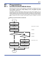
A7.1
Communications Mode Areas
Before data can be sent to remote equipment, communications conditions must be set
up. To support a variety of communications protocols, the F3RZ81-0F/F3RZ82-0F ladder
communication module allows many functions to be configured using the
communications mode areas.
For instance, while the transmission speed and the data format definition can be
specified using the SW1 rotary switch and the SW2 DIP switch on the right side of the
module respectively, they can also be set by software, by writing to the communications
mode areas from the FA-M3 CPU module using a program. This means that the settings
can be changed even after the ladder communication module is installed on the base
unit. For F3RZ82-0F, the SW1 and SW2 settings apply to both ports 1 and 2, but the
settings can be changed by software for individual ports.
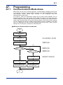
z Writing to communications mode area
Start
Verify communications
conditions.
Write data to
communications mode area.
Port 1: Data position no. 1857-1888
Port 2: Data position no. 1921-1952
Turn on Request to Set
Communications Mode relay.
Y35 for port 1
Y51 for port 2
OFF
Is Set Communications
Mode Completed relay on?
X03 for port 1
X19 for port 2
OFF
Is Set Communications
Mode Error relay on?
X09 for port 1
X25 for port 2
ON
ON
Check the setup error
information.
Turn off Request to Set
Communications Mode relay.
Turn off Request to Set
Communications Mode relay.
Set Communications Mode
Completed relay turns off.
Set Communications Mode
Error relay turns off.
Data position no. 1920 for port 1
Data position no. 1984 for port 2
End
IM 34M6H22-02E
2nd Edition : Jan. 30, 2008-00
A7-2
z Sample program
This sample program assumes the following conditions:
-
The module is installed in slot 3.
Port 1 is used for communications.
-
Transmission speed is 19200 bps.
***** Writing to communication mode area *****
*** Writing
19.2 kbps
transmission speed
*** If written normally
*** If setup error occurs
Read setup error
information
IM 34M6H22-02E
2nd Edition : Jan. 30, 2008-00
A7-3
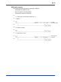
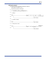
z Reading from communications mode area
Start
Turn on Request to Read
Communications Mode Status
relay.
Y36 for port 1
Y52 for port 2
OFF
Read Communications Mode
Status Completed relay on?
X04 for port 1
X20 for port 2
ON
Read mode status from
communications mode area.
Port 1: Data position no. 1889-1920
Port 2: Data position no. 1953-1984
Turn off Request to Read
Communications Mode Status
relay.
Read Communications Mode
Status Completed relay
turns off.
End
z Sample program
This sample program assumes the following conditions:
- The module is installed in slot 3.
- All the contents of the communications mode area for port 1 are to be read.
領
域
***** Reading from communications mode area *****
*** Request to read communications mode status
*** If communications mode status is read successfully
Read communication
mode status
IM 34M6H22-02E
2nd Edition : Jan. 30, 2008-00
A7-4
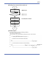
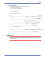
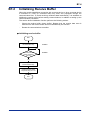
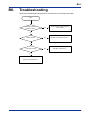
A7.2
Initializing Receive Buffer
When the module establishes connection with a remote device or when a remote device
is switched on, noise (or unwanted data) may arise and propagate through the
communications line. To avoid receiving unwanted data inadvertently, it is advisable to
initialize the receive buffer before starting communications, in addition to setting up the
communications conditions.
The receive buffer initialization function performs the following actions:
- Clears the receive buffer (rotary buffer). Beware that the receive data area is
different from the receive buffer and is not initialized by this function.
- Resets the communications controller.
z Initializing receive buffer
Start
Turn on Request to Initialize
Receive Buffer relay.
Y37 for port 1
Y53 for port 2
OFF
Is Initialize Receive
Buffer Completed
relay on?
X05 for port 1
X21 for port 2
ON
Turn off Request to Initialize
Receive Buffer relay.
Initialize Receive Buffer
Completed relay turns off.
End
IM 34M6H22-02E
2nd Edition : Jan. 30, 2008-00
A7-5
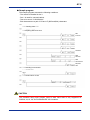
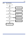
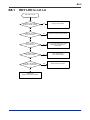
A7.3
Sending Data
z Send procedure
Start
Data position no. 1793 for port 1
Data position no. 1797 for port 2
Write send data byte count
Data position no. 1-384 for port 1
Data position no. 897-1280 for port 2
Write send data.
Y34 for port 1
Y50 for port 2
Turn on
Request to Send relay.
OFF
Is Send
Completed
relay on?
X02 for port 1
X18 for port 2
OFF
Is Send Error
relay on?
X08 for port 1
X24 for port 2
ON
ON
Check Send Data Status.
Turn off
Request to Send relay.
Turn off
Request to Send relay.
Send Completed Relay
turns off.
Send Error relay turns off.
Data position no. 1794 for port 1
Data position no. 1798 for port 2
End
CAUTION
-
This procedure assumes that default data position numbers are used for the send
data area.
The data position numbers will be different if the size of the send or receive data
area is redefined by a user.
IM 34M6H22-02E
2nd Edition : Jan. 30, 2008-00
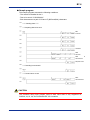
A7-6
z Sample program
This sample program assumes the following conditions:
- The module is installed in slot 3.
- Port 1 is used for communications.
- Text to be sent is "YOKOGAWA ".
- End characters are a pair of CR and LF ($0D and $0A) characters.
***** Sending data ******
*** Preparing data to be sent
Data
to be sent
Terminator
Write
send data
Write
send data size
Request to
send
*** If sending is successful
*** If a send error occurs
CAUTION
The character string input function used to store send data is only supported for
F3SP28, 38, 53, 58, and 59-N/H/F CPU modules.
IM 34M6H22-02E
2nd Edition : Jan. 30, 2008-00
A7-7
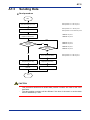
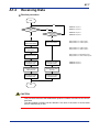
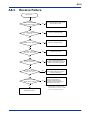
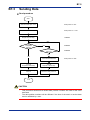
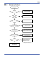
A7.4
Receiving Data
z Receive procedure
Start
OFF
Is Receive
Completed relay
on?
X01 for port 1
X17 for port 2
OFF
Is Receive Error
relay on?
X07 for port 1
X23 for port 2
ON
ON
Read
Receive Data Status.
Read
Receive Data Status.
Data position no. 1795 for port 1
Data position no. 1799 for port 2
Read receive data
byte count.
Data position no. 1796 for port 1
Data position no. 1800 for port 2
Read receive data.
Data position no. 385-896 for port 1
Data position no. 1281-1792 for port 2
Turn on
Read Receive Data
Completed relay.
Turn on
Read Receive Data
Completed relay.
Receive Completed
relay turns off.
Receive Error relay
turns off.
Turn off
Read Receive Data
Completed relay.
Turn off
Read Receive Data
Completed relay.
Y33 for port 1
Y49 for port 2
End
CAUTION
-
This procedure assumes that default data position numbers are used for the receive
data area.
The data position numbers will be different if the size of the send or receive data
area is re-defined by a user.
IM 34M6H22-02E
2nd Edition : Jan. 30, 2008-00
A7-8
z Sample program
This sample program assumes the following conditions:
- The module is installed in slot 3.
- Port 1 is used for communications.
***** Receiving data *****
*** If receiving is successful
Read receive data
status and size
Calculate
receive data size
Read
receive data
*** If a receive error occurs
Read
receive data status
CAUTION
The receive data size is stored in units of bytes in the module. You must convert the size
in bytes into size in words when reading the received data into the CPU module using
the READ instruction.
IM 34M6H22-02E
2nd Edition : Jan. 30, 2008-00
A8-1
A8.
Troubleshooting
These are troubleshooting flowcharts for common errors involving the module.
Error
Is sequence CPU
module in error?
Yes
Rectify the error of the sequence
CPU module.
No
Is RDY LED lit?
No
See A8.1, "RDY LED is not Lit."
No
See A8.2, "Send Error."
Yes
Is sending normal?
Yes
See A8.3, "Receive Error."
IM 34M6H22-02E
2nd Edition : Jan. 30, 2008-00
A8-2
A8.1
RDY LED is not Lit
RDY LED is not lit.
Is power supply module
receiving normal voltage?
No
Supply normal voltage.
No
Replace the power supply module.
No
Check total current consumption.
If it is out of the specification range,
replace the power supply or
base module.
No
Push the module in
until it clicks into place.
Yes
Replace the base module.
Yes
Is RDY LED on power
supply module lit?
Yes
Is RDY LED on
other modules lit?
Yes
Is the module inserted
in the slot correctly?
Yes
Does RDY LED light up if
installed in another slot?
No
Replace the
ladder communication module.
IM 34M6H22-02E
2nd Edition : Jan. 30, 2008-00
A8-3
A8.2
Send Failure
Send error
Is Send Error
relay on?
No
Replace the module.
Yes
Set send data byte count correctly.
Yes
The cable is loose or out of
specifications.
Yes
Is error code of
send status 0100?
No
Is error code of
send status 0201?
No
Is error code of
send status 0202?
Yes
DR check is specified so sending is
allowed only when DR is on. If DTE is
at the other end, ensure that its ER
signal is on.
Yes
CD check is specified so sending is
allowed only when CD is off. If DTE
is at the other end, ensure that its RS
signal is off.
No
Is error code of send status
0203?
No
Replace the module.
IM 34M6H22-02E
2nd Edition : Jan. 30, 2008-00
A8-4
A8.3
Receive Failure
Receive error
Is the remote equipment
sending data normally?
No
Ensure that the remote equipment is
sending data correctly.
No
See A7.4, "Receiving Data."
Yes
Is Receive Completed
relay on?
Yes
Is Receive Error relay on?
No
See A2.3, "External Wiring."
Yes
Does Receive Data Status
indicate an overrun error?
Yes
Replace the module.
Yes
Ensure that the data format
definition of the module is the same
as that of the remote equipment.
Yes
Ensure that the parity bit definition of
the module is the same as that of
the remote equipment.
Yes
Character-to-character receive
timeout occurred before a
terminator is detected or the
specified number of characters is
received (see note below).
No
Does Receive Data Status
indicate a framing error?
No
Does Receive Data Status
indicate a parity error?
No
Does Receive Data Status
indicate character timeout?
No
Note: Character-to-character receive timeout is
considered either as a receive error or the
normal completion of received data. For details,
see A4.1, "Communication Mode Areas."
Replace the module.
IM 34M6H22-02E
2nd Edition : Jan. 30, 2008-00
Appx. A1-1
Appendix A1. ASCII Code Table
High
Low
0
1
2
3
4
5
6
7
8
9
A
B
C
D
E
F
0
1
NUL
SOH
STX
ETX
EOT
ENQ
ACK
BEL
BS
HT
LF
VT
FF
CR
SO
SI
DLE
DC1
DC2
DC3
DC4
NAK
SYN
ETB
CAN
EM
SUB
ESC
FS
GS
RS
US
2
SP
!
"
#
$
%
&
'
(
)
*
+
,
.
/
3
0
1
2
3
4
5
6
7
8
9
:
;
<
=
>
?
4
@
A
B
C
D
E
F
G
H
I
J
K
L
M
N
O
5
P
Q
R
S
T
U
V
W
X
Y
Z
[
¥
]
^
_
6
`
a
b
c
d
e
f
g
h
i
j
k
l
m
n
o
7
p
q
r
s
t
u
v
w
x
y
z
{
|
}
~
DEL
IM 34M6H22-02E
2nd Edition : Jan. 30, 2008-00
Blank Page
Index A-1
FA-M3
Ladder Communication Module
Part A: F3RZ81-0F/F3RZ82-0F
IM 34M6H22-02E 2nd Edition
INDEX
B
break signal ..............................................A4-4, A6-3
break transmission interval............. A4-2, A4-3, A4-4
C
CD check ...............................A2-1, A4-2, A4-3, A4-5
character length ........... A2-1, A2-5, A4-2, A4-3, A4-4
character-to-character
receive timeout, detecting ....................... A6-3
character-to-character
timeout interval ..................... A4-2, A4-3, A4-5
character-to-character
timeout processing .........................A4-2, A4-3
clear-to-send
timeout interval ............A2-2, A4-2, A4-3, A4-4
communications condition setup ..............A5-1, A7-1
communications mode area .............................. A4-2
communications mode area, reading from ........ A7-3
communications mode area, writing to .............. A7-1
communications mode setup area .................... A4-2
communications mode status area.................... A4-3
connecting to a modem ..................................... A2-8
connecting to an RS-232-C device.................... A2-7
connector pin assignment ................................. A2-6
control line status............................ A3-1, A4-3, A4-5
receive buffer, initializing................. A3-1, A3-2, A7-4
receive data area ...................A4-1, A4-2, A4-3, A4-6
receive data area size..................... A4-1, A4-5, A4-6
receive data byte count................... A4-1, A4-6, A4-7
receive data status.......................... A4-1, A4-6, A4-7
receive error..........................A3-1, A3-2, A4-2, A4-3,
A4-5, A6-3, A7-7, A8-4
receive procedure .............................................. A7-7
receive text length ............................................. A4-4
received text, format of ............................A2-1, A6-1
RS control .............................A2-1, A4-2, A4-3, A4-5
S
send and receive data areas ....................A4-1, A4-6
send data area .......................A4-1, A4-2, A4-3, A4-6
send data area size ........................ A4-1, A4-5, A4-6
send data byte count ................................A4-1, A4-6
send error............A3-1, A3-2, A4-4, A4-5, A7-5, A8-3
send procedure.................................................. A7-5
send status................................................A4-1, A4-7
start character of receive text ...................A4-2, A4-4
stop bits..................................A2-1, A4-2, A4-3, A4-4
T
terminator...............................A2-1, A4-2, A4-3, A6-2
transmission speed switch (SW1) ............A2-2, A2-4
D
data format switch (SW2) ............... A2-2, A2-4, A2-5
DR check ...............................A2-1, A4-2, A4-3, A4-5
E
end character of
receive text ...................A4-2, A4-3, A4-4,A6-2
ER control ..............................A2-1, A4-2, A4-3, A4-5
error code .................................................A4-7, A8-3
extended send/receive data area .............A4-1, A4-6
I
input relays ........................................................ A3-2
O
output relays ...................................................... A3-1
P
parity ............................ A2-1, A2-5, A4-2, A4-3, A4-4
R
RDY LED ....................................... A2-2, A8-1, A8-2
IM 34M6H22-02E
2nd Edition : Jan. 30, 2008-00
Blank Page
TOC B-1
FA-M3
Ladder Communication Module
Part B: F3RZ91-0F
IM 34M6H22-02E 2nd Edition
CONTENTS
Applicable Product ....................................................................................i
Important ...................................................................................................ii
Introduction............................................................................................viii
Copyrights and Trademarks ...................................................................ix
Part B: F3RZ91-0F
B1. Overview .....................................................................................B1-1
B2. Specifications .............................................................................B2-1
B2.1
B2.2
B2.3
B2.4
Standard Specifications........................................................................B2-1
Model and Suffix Codes.....................................................................B2-1
Operating Environment ......................................................................B2-1
General Specifications .......................................................................B2-1
Physical Specifications.......................................................................B2-1
Function Specifications ......................................................................B2-1
Components and Functions ...............................................................B2-2
External Dimensions ..........................................................................B2-2
Switch Setup ..........................................................................................B2-3
Switches on the Module.....................................................................B2-3
External Wiring ......................................................................................B2-5
RS-422-A/RS-485 Terminal Block......................................................B2-5
Connecting Master and Slave............................................................B2-5
Terminating Resistor ..........................................................................B2-6
Attaching/Detaching the Module..........................................................B2-7
B3. List of I/O Relays ........................................................................B3-1
B3.1
B3.2
Output Relays ........................................................................................B3-1
Input Relays ...........................................................................................B3-2
B4. List of Data Areas .......................................................................B4-1
B4.1
B4.2
Communications Mode Areas ..............................................................B4-2
Communications Mode Setup Area ...................................................B4-2
Communications Mode Status Area...................................................B4-3
Send and Receive Data Areas ..............................................................B4-5
B5. Startup Preparation ....................................................................B5-1
B6. Data Communications................................................................B6-1
B6.1
B6.2
Format of Received Text.......................................................................B6-1
Break Signal...........................................................................................B6-2
IM 34M6H22-02E
2nd Edition : Jan. 30, 2008-00
TOC B-2
B7. Programming ..............................................................................B7-1
B7.1
B7.2
B7.3
B7.4
Communications Mode Areas ..............................................................B7-1
Initializing Receive Buffer.....................................................................B7-4
Sending Data..........................................................................................B7-5
Receiving Data.......................................................................................B7-7
B8. Troubleshooting .........................................................................B8-1
B8.1
B8.2
B8.3
RDY LED is not Lit.................................................................................B8-2
Send Failure ...........................................................................................B8-3
Receive Failure ......................................................................................B8-4
Appendix B1. ASCII Code Table ............................................. Appx. B1-1
Index ........................................................................................... Index B-1
Revision Information .................................................................................i
IM 34M6H22-02E
2nd Edition : Jan. 30, 2008-00
B1-1
B1.
Overview
The F3RZ91-0F Ladder Communication Module can be used with an FA-M3 CPU
module for RS-422/485 communications. It has one terminal block, or port, which
supports a maximum transmission distance of 1200 m.
Any input relay of the F3RZ91-0F may be used to raise an interrupt.
Table B1.1 Models of Ladder Communication Module
Model
F3RZ91-0F
Description
RS-422/485 ladder communication module
IM 34M6H22-02E
2nd Edition : Jan. 30, 2008-00
Blank Page
B2-1
B2.
Specifications
B2.1
Standard Specifications
Model and Suffix Codes
Suffix Code
Model
F3RZ91
-0F
Style Code
……
Option Code
……
Description
Max 115.2 kbps, one RS-422/485 port
Operating Environment
The F3RZ91-0F may be used with all CPU modules.
General Specifications
Item
Operating
temperature
Operating
humidity
Operating
environment
Specifications
Item
Specifications
0 to 55°C
Storage temperature
-20 to 75°C
10 to 90% RH (non-condensing)
Storage humidity
10 to 90% RH (non-condensing
Must of free of corrosive gases,
flammable gases and heavy dust
Physical Specifications
Item
Interface
Number of ports
Transmission
distance
Connector
Specifications
EIA RS-232-C compliant
1 (isolated)
Item
Specifications
Current consumption 350 mA
External dimensions 28.9 (W) x 100 (H) x 83.2 (D) mm*
1200 m max.
Weight
120 g
Terminal block
*: Dimensions excluding protrusions. For details, see the External Dimensions drawing.
Function Specifications
Item
Connection method
Transmission mode
Synchronization
Communication protocol
Character length
Data format
Stop bits
Parity bit
Specifications
Point to point
Full-duplex/half-duplex
Start-stop synchronization
No protocol
7 or 8 bits
1 or 2 bits
None, even, or odd
300, 600, 1200, 2400, 4800, 9600, 14400, 19200, 28800,
Transmission speed
38400, 57600, 76800, or 115200 bps
Communication
Send buffer
Text buffer (1792 bytes max.*3)
buffer
Receive buffer
8192-byte rotary buffer (FIFO buffer)
- Yes or no
Start character
- Any single character
- Yes or no
End character (terminator) - Up to 2 characters long, any characters
Format of
- Also used as send terminator.
received text
Text length
Can be specified as any number between 1 and 1792*3.
Character-to-character
0 to 32760 ms in 1 ms increments,
timeout interval
accurate to 1 ms (0 means not monitored)
0 to 32760 ms in 1 ms increments,
Clear-to-send timeout interval
accurate to 1 ms (0 means not monitored)
Break transmission interval
1 to 32760 ms in 1 ms increments, accurate to 1 ms
Default
―
―
―
―
*1
*1
*1
*2
―
―
No
$0D and $0A
(CR-LF)
1024
1.5 s
Not
monitored
400 ms
*1: Default values are set with the data format switch (SW2).
*2: Default values are set with the transmission speed switch (SW1).
*3: May be increased up to 1792 bytes using the Send Data Area Size and Receive Data Area Size data registers.
IM 34M6H22-02E
2nd Edition : Jan. 30, 2008-00
B2-2
Components and Functions
z Right side view
z Front view
Indicator RDY:
RDY
RZ91-1F
RS-422
Lit when the internal
circuit is functioning
normally.
Front
Rear
TERMINATOR
2-
4-WIRE
OFF
SD A
SD B
Terminating resistor switch:
SW1
Transmission speed switch
If a terminator is used,
select between 2- and 4wire system.
SW3
O
F
F
RD A
RD B
RS-422-A/RS-485
Terminal block:
SG
(Six M3.5 screws)
1
2
3
4
5
6
7
8
SW2
O
F
F
1
2
3
4
5
6
7
8
Sets the transmission
speed of the module.
Data format switch
Defines the format of
communication data.
This switch is not
used.
This figure is drawn with the
panel cover removed.
SHIELD
External Dimensions
(Unit: mm)
12.1
28.9
83.2
2
100
IM 34M6H22-02E
2nd Edition : Jan. 30, 2008-00
B2-3
B2.2
Switch Setup
Switches on the Module
Always set the three switches on the side of the F3RZ91-0F module before installing it
on the FA-M3 base module. See Figure B2.1 for the switch names and locations.
z Right side view
Front
Rear
SW1
Transmission speed switch
SW3
O
F
F
1
2
3
4
5
6
7
8
Sets the transmission
speed of the module.
SW2
O
F
F
1
2
3
4
5
6
7
8
Data format switch
Defines the format of
communication data.
This switch is not
used.
This figure is drawn with the
panel cover removed.
Figure B2.1 F3RZ91-0F Switches
z Transmission speed switch (SW1)
This is a hexadecimal rotary switch for setting up the transmission speed of the module.
You can set the switch by inserting a small flat-blade screwdriver in its arrow-shaped slit
and rotating it to a desired position between 1 and C (positions D to F are not available).
The factory setting is ‘C’ (= 115.2 kbps).
SW1
Position
0
1
2
3
4
5
6
7
8
9
A
B
C
D-F
Transmission
Speed (bps)
300
600
1200
2400
4800
9600
14400
19200
22800
38400
57.6K
76.8K
115.2K
------
Remarks
Factory setting
Not available
Figure B2.2 F3RZ91-0F Transmission speed Switch
IM 34M6H22-02E
2nd Edition : Jan. 30, 2008-00
B2-4
z Data format switch (SW2)
This is an 8-element DIP switch for defining a character frame. Elements 1-4 may be set
to either the ON or OFF position to define character length, parity and stop bits. The
factory setting has element 1 set to ON and elements 2-8 set to OFF.
O
F
F
1
2
3
4
5
6
7
8
SW2 Elements
1
2
3
4
5
6
7
8
Function
Character length
Parity
Stop bits
Not used
Not used
Not used
Not used
OFF
7 bits
No
Odd
1 bit
-------------
ON
8 bits
Yes
Even
2 bits
-------------
Default
8 bits
No parity
---1 bit
-------------
ON
OFF
OFF
OFF
OFF
OFF
OFF
OFF
- SW2-3 is available only when SW2-2 is set to ON (= using parity).
- Always set SW2-5 to SW2-8 to OFF.
Figure B2.3 F3RZ91-0F Data format Switch
z Reserved switch (SW3)
The F3RZ91-0F does not use the SW3 switch. The module must be used with all
elements of this switch set to OFF (factory setting).
O
F
F
1
2
3
4
5
6
7
8
SW3 Elements
1
2
3
4
5
6
7
8
Function
Not used
Not used
Not used
Not used
Not used
Not used
Not used
Not used
OFF
ON
Default
OFF
OFF
OFF
OFF
OFF
OFF
OFF
OFF
Figure B2.4 F3RZ91-0F Reserved Switch
CAUTION
Ensure that all unused switch elements are set to OFF.
IM 34M6H22-02E
2nd Edition : Jan. 30, 2008-00
B2-5
B2.3
External Wiring
RS-422-A/RS-485 Terminal Block
The terminal block of the F3RZ91-0F has six terminals (with M3.5 screws) as follows:
SD A
SD A
Send data A
→
SD B
SD B
Send data B
→
RD A
RD A
Receive data A ←
RD B
RD B
Receive data B ←
SG
SG
Signal ground
SHIELD
SHIELD
M3.5
7.3 mm
8.6 mm
Figure B2.5 F3RZ91-0F Terminal Block
Table B2.1 Compatible Wires and Crimp-on Terminals
Cable type
Rated temperature
Connection method
Compatible crimp-on
terminals and wires
Tightening torque
Shielded twist-pair cable
75°C or higher
Using crimp-on terminals
Vendor
Japan Solderless Terminal Mfg
Co., Ltd.
Nippon Tanshi Co., Ltd.
Japan Solderless Terminal Mfg
Co., Ltd.
Japan Solderless Terminal Mfg
Co., Ltd.
0.8 N-m (7.1 lbfxin)
Model
V1.25-M3
Compatible Wire
AWG22 to 18 (0.33 to 0.82 mm2)
(copper wire)
RAV1.25-3.5
V1.25-M4
AWG16 to 14 (1.3 to 2.1 mm2)
(copper wire)
V2-M4
Connecting Master and Slave
z 4-wire system
Supposing the F3RZ91-0F is a master, send and receive lines must be crossed between
the F3RZ91-0F and the slave equipment.
F3RZ91-0F
Slave equipment
Slave equipment
SD A
SD A
SD A
SD B
SD B
SD B
RD A
RD A
RD A
RD B
RD B
RD B
SG
SG
SG
SHIELD
SHIELD
SHIELD
Figure B2.6 4-wire System Connection
IM 34M6H22-02E
2nd Edition : Jan. 30, 2008-00
B2-6
z 2-wire system
At the F3RZ91-0F terminal block, short SD A with RD A, and SD B with RD B, using a
jumper wire.
Slave equipment
F3RZ91-0F
Slave equipment
SD A
SD B
RD A
RD B
SG
SG
SHIELD
SHIELD
SG
SHIELD
Figure B2.7 2-wire System Connection
CAUTION
If the 2-wire system connection is used, also set the 2-wire/4-wire selection parameter
(data position No.: 918) of the communications mode area to 2-wire.
Terminating Resistor
If the F3RZ91-0F is at one end of the communication line, it must use the internal
terminating resistor, or terminator, according to the wiring system used.
Set the terminating resistor switch to 4-WIRE for 4-wire system, or 2-WIRE for 2-wire
system. Set the switch to OFF if the F3RZ91-0F is not at an end of the line.
TERMINATOR
4-WIRE
2OFF
Figure B2.8 F3RZ91-0F Terminating Resistor Switch
IM 34M6H22-02E
2nd Edition : Jan. 30, 2008-00
B2-7
B2.4
Attaching/Detaching the Module
Attaching the Module
Figure B2.9 shows how to attach this module to the base module. First hook the anchor
slot at the bottom of the module to be attached onto the anchor pin on the bottom of the
base module. Push the top of the module toward the base module until the
anchor/release button (yellow button) clicks into place.
CAUTION
Always switch off the power before attaching or detaching the module.
Base Module
Anchor
pin
Ladder
Communication
Module
F01.VSD
Figure B2.9 Attaching/Detaching the Module
CAUTION
Do not bend the connector on the rear of the module by force during the above
operation. If the module is pushed with improper force, the connector may bend, causing
an error.
Detaching the Module
To remove this module from the base module, reverse the above operation.
Press the anchor/release button (yellow button) on the top of this module to unlock it
and tilt the module away from the base module.
IM 34M6H22-02E
2nd Edition : Jan. 30, 2008-00
B2-8
Attaching the Module in Intense Vibration Environments
If the module is used in intense vibration environments, fasten the module with a screw.
Use screws of type listed in the table below.
Insert these screws into the screw holes on top of the module and tighten them with a
Phillips screwdriver.
Screw Required
M4-size binder screw 12 to 15 mm long
(or 14-15 mm long if fitted with a washer)
F02R1.VSD
Figure B2.10 Securing Module Using Screws
IM 34M6H22-02E
2nd Edition : Jan. 30, 2008-00
B3-1
B3.
List of I/O Relays
The ladder communication module has 32 input and 32 output relays for interfacing with
the FA-M3 CPU module. Each of the input relays can be configured to raise an
interrupt.
B3.1
Output Relays
Table B3.1 Output Relays
Output Relay
Number
Y33
Read Received Data
Completed
Y34
Request to Send
Y35
Request to Set
Communications Mode
Y36
Request to Read
Communications Mode
Status
Y37
Request to Initialize
Receive Buffer
Y38
Request to Send Break
Y39 to
Y64
Description
Output Relay Name
Turn on this relay after reading data from the receive
data area. Turning on this relay turns off X01
(receive completed normally) and X07 (receive
error), and the module is ready to receive new data into
the receive data area.
Turn on this relay after having stored send data size and
send data to the registers. If data is sent successfully
following this request, X02 turns on, and if an error
occurs, X08 turns on.
Turn on this relay after having stored communications
mode setting in the communications mode area. If setup
is successful following this request, X03 turns on,
and if an error occurs, X09 turns on.
Turn on this relay to read the contents of the
communications mode area and the control line status.
If the request is completed successfully, X04 turns
on.
Turn on this relay to initialize the receive buffer and the
communications controller. X05 turns on after
successful initialization.
Turn on this relay to send a break signal. If a break is
sent successfully following this request, X06 turns
on, and if an error occurs, X08 turns on.
Reserved
IM 34M6H22-02E
2nd Edition : Jan. 30, 2008-00
B3-2
B3.2
Input Relays
Table B3.2 Input Relays
Input Relay
Number
X01
Receive Completed
X02
Send Completed
X03
Set Communications Mode
Completed
X04
Read Communications
Mode Status Completed
X05
Initialize Receive Buffer
Completed
X06
Send Break Completed
X07
Receive Error
X08
Send Error
X09
Set Communications Mode
Error
X10 to
X32
Description
Input Relay Name
This relay turns on when received data is transferred
from the receive buffer to the receive data area.
Turning on Y33 turns off this relay.
This relay turns on when data is successfully sent
following a request to send.
Turning off Y34 turns off this relay.
This relay turns on when a request to set
communications mode is successfully completed.
Turning off Y35 turns off this relay.
This relay turns on when the communications mode
status has been successfully read out and stored.
Turning off Y36 turns off this relay.
This relay turns on when the receive buffer and the
communications controller have been successfully
initialized.
Turning off Y37 turns off this relay.
This relay turns on when a break signal has been sent
successfully.
Turning off Y38 turns off this relay.
This relay turns on if error is detected during data
receiving.
Turning on Y33 turns off this relay.
This relay turns on if error is detected when processing a
request to send or a request to send break.
Turning off Y34 or Y38 turns off this relay.
This relay turns on if error is detected during
communications mode setup.
Turning off Y35 turns off this relay.
Reserved
IM 34M6H22-02E
2nd Edition : Jan. 30, 2008-00
B4-1
B4.
List of Data Areas
The ladder communication module has send and receive data areas and
communications mode areas for interfacing with the FA-M3 CPU module. The
communications mode areas are used to store communications mode settings, and the
send and receive data areas are used to store data to be sent and data received
respectively.
Data Position No.
1
Send data area
(port 1)
Receive data area
(port 1)
Send data byte count
Send status
Receive data status
Receive data byte count
(port 1)
(port 1)
(port 1)
(port 1)
Communications mode area
(port 1)
384
385
896
897
898
899
900
905
968
CAUTION
-
You may customize the send data area size and receive data area size to use data
positions between 1 and 896.
Data positions above 896 are fixed and cannot be customized.
IM 34M6H22-02E
2nd Edition : Jan. 30, 2008-00
B4-2
B4.1
Communications Mode Areas
Data Position No.
905
936
937
968
Setup area
Communications mode area
Status area
The communications mode area is divided into two sub-areas: setup area and status
area. A user program writes communications mode settings to the setup area before
issuing a request to set communications mode. It reads the status area to check the
internal communications mode parameters of the module.
Communications Mode Setup Area
Data
Position No
905
906
907
908
Description*2
Character-to-character timeout
processing
Character length
Stop bits
Parity
909
Transmission speed (in bps)
910
911
Reserved
Break transmission interval
0: receive successful; 1: receive error
0
0: 7 bits; 1: 8 bits
0: 1 bit; 1: 2 bits
0: none; 1: odd; 2: even
*1
0: 300
1: 600
2: 1200
3: 2400
4: 4800
5: 9600
6: 14400
Start character of receive text
*1
*1
7: 19200
8: 28800
9: 38400
10: 57600
11: 76800
12: 115200
*2
1 to 32760 (ms)
15
912
Default
400
8 7
0
0
0
Start character
- All 0's if no start character is used
15
913
End character (terminator) of
receive text
914
Receive text length
915
916
917
918
919 to
934
935
936
8 7
0
First terminator
Second terminator
- All 0's for the first terminator if only one end character is
used.
- All 0's for the first and second terminators if no end
character is used.
0 to 1024 (number of characters on the line)*3
0 means no receiving.
Character-to-character timeout 0 to 32760 (ms)
interval
0 means not monitored
$0D $0A
(CR LF)
1024
1500
Reserved
2-wire/4-wire selection
0 for 4-wire system, 1 for 2-wire system
0
Reserved
- In units of words
- Total size for send and receive data areas
Receive data area size (port 1) must not exceed 896 words (1792 bytes)
Send data area size (port 1)
384
512
*1: The default value is set with the SW2 switch.
*2: The default value is set with the SW1 switch.
*3: Depends on receive data area size.
CAUTION
Both the break transmission interval and receive character-to-character timeout interval
have an error of 1 ms so the actual duration may be up to1 ms shorter than the specified
value.
IM 34M6H22-02E
2nd Edition : Jan. 30, 2008-00
B4-3
Communications Mode Status Area
Data Position No
Character-to-character timeout
processing
Character length
Stop bits
Parity
937
938
939
940
941
Transmission speed (in bps)
942
943
Reserved
Break transmission interval
944
Start character of receive text
Description
0: receive successful
1: receive error
0: 7 bits;
1: 8 bits
0: 1 bit;
1: 2 bits
0: none;
1: odd;
2: even
7
8
9
10
11
12
0: 300
1: 600
2: 1200
3: 2400
4: 4800
5: 9600
6: 14400
: 19200
: 28800
: 38400
: 57600
: 76800
: 115200
1 to 32760 (ms)
15
8
7
0
0
Start character
・All 0's if no start character is used
15
945
End character (terminator) of receive
text
946
Receive text length
8
7
0
First terminator
Second terminator
・All 0's for the first terminator if only one end character is used
・All 0's for the first and second terminators if no end character is used
0 to 1024 (number of characters on the line)*3
0 means no receiving
0 to 32760 (ms);
Character-to-character timeout interval
0 means not monitored
947
948
949
950
951-964
965
966
967
2-wire/4-wire selection
Reserved
Send data area size
Receive data area size
Reserved
968
Setup error information
Reserved
0 for 4-wire system, 1 for 2-wire system
15
8
7
0
Data position no.
z Character-to-character timeout processing
Character-to-character receive timeout is always monitored. When timeout occurs, it is
considered either a receive error (the Receive Error input relay turns on) or the normal
completion of receive data (the Receive Completed input relay turns on) according to
this setting.
If this setting is 0, a character-to-character receive timeout is always considered the
normal completion of receive data and the Receive Completed input relay turns on. This
setting is useful when the receive text length or the end character cannot be specified.
When a character-to-character receive timeout occurs, the character-to-character
receive timeout bit of the Receive data Status register turns on irrespective of this
setting.
z Character length
This setting is used to specify how many bits make up one character.
z Stop bits
This setting is used to specify how many bits are used to signify the end of a character.
z Parity
This setting is used to define the parity bit, which is used for error detection.
IM 34M6H22-02E
2nd Edition : Jan. 30, 2008-00
B4-4
z Transmission speed
This setting is used to specify the transmission speed.
z Break transmission interval
This setting is used to specify the duration of a break signal. It cannot be set to 0 ms.
z Start character of receive text
This setting is used to define the start character that signifies the beginning of receive
text. No start character is attached to send text.
z End character of receive text
This setting is used to define the end character that signifies the end of receive text. No
end character is attached to send text.
z Receive text length
This setting is used to specify the number of characters for delimiting receive text. This
setting may not exceed a user-defined receive data area size.
CAUTION
-
-
If the receive text length is set to a value larger than the receive data area size, the
receive data area size is used. If the receive text length is set to a value larger than
1792, however, a Set Communications Mode Error is generated.
The receive text length is ignored if the receive data area size is set to 0.
-
If the receive text length is set to 0, the module can receive no data.
z Character-to-character timeout interval
This setting is used to define the character-to-character receive timeout interval, which is
the maximum allowable lapse between two successive characters in the same text.
When a timeout occurs, whether it is considered a receive error or the normal
completion of receive text depends on the character-to-character timeout processing
setting.
z Send data area size, receive data area size
Use these settings to specify the size of the send and receive data areas respectively.
A total space of 896 words (1792 bytes) may be freely shared among the send and
receive data areas. Specify the size in word (two bytes) units.
CAUTION
-
A send error is generated if the send data area size of a port is set to 0, but a
request to send is issued for that port.
If the receive data area size of a port is set to 0, it will not be available for receiving.
-
Do not change the setting of the send data area size or the receive data area size
during communication.
-
If the setting of the send or receive data area size is changed during
communication, beware that there may be old data remaining in the data areas.
IM 34M6H22-02E
2nd Edition : Jan. 30, 2008-00
B4-5
B4.2
Send and Receive Data Areas
z Allocation of send and receive data areas
Data position No.
1
Send data area
(port 1)
Receive data area
(port 1)
Send data byte count
Send status
Receive data status
Receive data byte count
(port 1)
(port 1)
(port 1)
(port 1)
Communications mode area
(port 1)
384
385
896
897
898
899
900
905
968
CAUTION
-
You may customize the send data area size and receive data area size for using
data positions between 1 and 896.
-
Data positions above 896 are fixed and cannot be customized.
z Send data area
This area is used to store data to be sent.
z Receive data area
This area is used to store data received.
z Send data byte count
This area is used to store the number of bytes to be sent. Following a request to send,
data is sent until the specified number of bytes is reached.
z Send status
This area is used to store the completion status after transmission.
Status
Send successful
Send data size error
Error Code
(Decimal)
0000
0100
Description
IM 34M6H22-02E
2nd Edition : Jan. 30, 2008-00
B4-6
z Receive data status
This area stores the status of the received text stored in the receive data area. The
status is a combination of error bits (see the table below). An error bit is turned on if the
corresponding error is detected for any byte of the received text. If an error bit is turned
on, there is no way to tell which byte is the cause.
15 to 06
Reserved
05
ORER
ORER
FER
PER
IBOF
RCTO
BREAK
04
FER
03
PER
02
IBOF
01
RCTO
00
BREAK
: Overrun error
: Framing error
: Parity error
: Receive buffer overflow
: Character-to-character receive timeout
: Break signal received
z Receive data byte count
This area stores the number of bytes of data received. By reading the value stored in
this area, a program can determine the size of received data. The end character in
received data is automatically deleted when the received data is stored in the receive
data area.
IM 34M6H22-02E
2nd Edition : Jan. 30, 2008-00
B5-1
B5.
Startup Preparation
The flowchart below shows the things to be done to prepare for communications.
Start
See Also:
Set up communications
conditions by hardware.
Set the module and the
remote equipment with the
same communications
conditions.
Install the module
on the base module.
B2.4, "Attaching/detaching
the Module"
Connect the module to
equipment through a
communications line.
Writing to
communications mode areas
necessary?
Yes
B2.3, "External Wiring"
No
Not necessary if the
settings with the
switches on the side of
the module are used
as they are.
B3, "List of I/O Relays"
B4.1, "Communications Mode Areas"
B7.1, "Communications Mode Areas"
Write to
communication mode areas.
Initialize receive buffer.
End
B2.2, "Swtich Setup"
The receive buffer
should be initialized to
discard any unwanted
data due to electric
noise that may be
present on the
communications line.
B7.2, "Initializing Receive Buffer"
IM 34M6H22-02E
2nd Edition : Jan. 30, 2008-00
Blank Page
B6-1
B6.
Data Communications
B6.1
Format of Received Text
The F3RZ91-0F ladder communication module may recognize a block of received text
by any of the following three means:
- By receiving a terminator
-
By receiving the number of characters designated by the Receive Text Length
setting in the communications mode area
-
By detecting a character-to-character receive timeout
CAUTION
-
A block of received text is recognized when any of the above three conditions is
met.
You may explicitly disable individual conditions if so desired.
-
However, you may not disable the condition defined by the Receive Text Length
setting.
z Receiving a terminator
A block of text is recognized when a terminator (end characters) is received. The default
terminator is the CR-LF character pair.
Example: If ETX ($03) is used as a terminator
Receive data
A
B
C
ETX
D
E
Received text 1
F
G
ETX
Received text 2
z Receive Text Length setting
A block of text is recognized when the number of bytes designated by the Receive Text
Length setting (between 1 and 1024) is received. If a start character of receive text is
specified, bytes for received text are counted starting from the character following the
start character. The default value for the Receive Text Length setting is 1024 (bytes).
Example 1: Receive Text Length is set to 4 (bytes)
Receive data
A
B
C
Received text 1
D
E
F
G
H
Received text 2
IM 34M6H22-02E
2nd Edition : Jan. 30, 2008-00
B6-2
Example 2: Receive Text Length is set to 6 (bytes) with the use of start character
STX ($02) and terminator ETX ($03)
Start character
of received text
Start character
of received text
A
B
STX
Discarded
P
Q
R
T
S
Received text 1
(6 bytes received)
U
STX
E
Terminator
N
D
ETX
Received text 2
(terminator detected)
Any data arriving after the
end of text 1 and before the
start of text 2 is discarded.
z Detecting a character-to-character receive timeout
A block of text is recognized when the next character is not received after a specified
timeout interval. This is especially useful for receiving binary data or text with no
terminator.
The default character-to-character timeout interval is 1500 ms
Example: Character-to-character timeout interval is set to 1000 ms and no
terminator is used in receive data
Receive data (with no terminator)
Receive data
Received text
Character-to-character
timeout interval
(1000 ms or longer)
When a character-to-character receive timeout occurs, it is either considered the normal
end of received text as discussed above or a receive error depending on the Characterto-Character Timeout Processing setting.
B6.2
Break Signal
The break signal is a special signal consisting of all ‘1’ bits, which is sent to generate a
framing error. The ladder communication module is capable of sending a break signal,
as well as recognizing a break signal.
IM 34M6H22-02E
2nd Edition : Jan. 30, 2008-00
B7-1
B7.
Programming
B7.1
Communications Mode Areas
Before data can be sent to remote equipment, communications conditions must be set
up. To support a variety of communications protocols, the F3RZ91-0F ladder
communication module allows many functions to be configured using the
communications mode areas.
For instance, while the transmission speed and the data format definition can be
specified using the SW1 rotary switch and the SW2 DIP switch on the right side of the
module respectively, they can also be set by software, by writing to the communications
mode areas from the FA-M3 CPU module using a program. This means that the settings
can be changed even after the ladder communication module is installed on the base
unit.
z Writing to communications mode area
Start
Verify communications
conditions.
Write data to
communications mode area.
Data position no. 905-936
Turn on Request to Set
Communications Mode relay.
Y35
OFF
Is Set Communications
Mode Completed relay on?
X03
OFF
Is Set Communications
Mode Error relay on?
X09
ON
ON
Check the setup error
information.
Turn off Request to Set
Communications Mode relay.
Turn off Request to Set
Communications Mode relay.
Set Communications Mode
Completed relay turns off.
Set Communications Mode
Error relay turns off.
Data position no. 968
End
IM 34M6H22-02E
2nd Edition : Jan. 30, 2008-00
B7-2
z Sample program
This sample program assumes the following conditions:
-
The module is installed in slot 3.
Transmission speed is 19200 bps.
***** Writing to communication mode area *****
*** Writing
19.2 kbps
transmission speed
*** If written normally
*** If setup error occurs
Read setup error
information
IM 34M6H22-02E
2nd Edition : Jan. 30, 2008-00
B7-3
z Reading from communications mode area
Start
Turn on Request to Read
Communications Mode Status
relay.
Y36
OFF
Read Communications Mode
Status Completed relay on?
X04
ON
Read mode status from
communications mode area.
Data position no. 937-968
Turn off Request to Read
Communications Mode Status
relay.
Read Communications Mode
Status Completed relay
turns off.
End
z Sample program
This sample program assumes the following conditions:
- The module is installed in slot 3.
- All the contents of the communications mode area for port 1 are to be read.
? ?
***** Reading from
communications mode area *****
*** Request to read communications mode status
*** If communications mode status is read successfully
Read communication
mode status
IM 34M6H22-02E
2nd Edition : Jan. 30, 2008-00
B7-4
B7.2
Initializing Receive Buffer
When the module establishes connection with a remote device or when a remote device
is switched on, noise (or unwanted data) may arise and propagate through the
communications line. To avoid receiving unwanted data inadvertently, it is advisable to
initialize the receive buffer before starting communications, in addition to setting up the
communications conditions.
The receive buffer initialization function performs the following actions:
- Clears the receive buffer (rotary buffer). Beware that the receive data area is
different from the receive buffer and is not initialized by this function.
- Resets the communications controller.
z Initializing receive buffer
Start
Turn on Request to Initialize
Receive Buffer relay.
Y37
OFF
Is Initialize Receive
Buffer Completed
relay on?
X05
ON
Turn off Request to Initialize
Receive Buffer relay.
Initialize Receive Buffer
Completed relay turns off.
End
IM 34M6H22-02E
2nd Edition : Jan. 30, 2008-00
B7-5
B7.3
Sending Data
z Send procedure
Start
Data position no. 897
Write send data byte count.
Data position no. 1-384
Write send data.
Turn on
Request to Send relay.
Y34
OFF
Is Send
Completed
relay on?
X02
OFF
Is Send Error
relay on?
X08
ON
ON
Check Send Data Status.
Turn off
Request to Send relay.
Turn off
Request to Send relay.
Send Completed Relay
turns off.
Send Error relay turns off.
Data position no. 898
End
CAUTION
-
This procedure assumes that default data position numbers are used for the send
data area.
The data position numbers will be different if the size of the send or receive data
area is redefined by a user.
IM 34M6H22-02E
2nd Edition : Jan. 30, 2008-00
B7-6
z Sample program
This sample program assumes the following conditions:
- The module is installed in slot 3.
- Text to be sent is "YOKOGAWA ".
- End characters are a pair of CR and LF ($0D and $0A) characters.
***** Sending data ******
*** Preparing data to be sent
Data
to be sent
Terminator
Write
send data
Write
send data size
Request to send
*** If sending is successful
*** If a send error occurs
Read
send data status
CAUTION
The character string input function used to store send data is only supported for
F3SP28, 38, 53, 58, and 59-N/H/F CPU modules.
IM 34M6H22-02E
2nd Edition : Jan. 30, 2008-00
B7-7
B7.4
Receiving Data
z Receive procedure
Start
OFF
Is Receive
Completed relay
on?
X01
OFF
Is Receive Error
relay on?
X07
ON
ON
Read
Receive Data Status.
Register No. 899
Read
Receive Data Status.
Read receive data
byte count.
Register No. 900
Register Nos. 385-896
Read receive data.
Turn on
Read Receive Data
Completed relay.
Turn on
Read Receive Data
Completed relay.
Receive Completed
relay turns off.
Receive Error relay
turns off.
Turn off
Read Receive Data
Completed relay.
Turn off
Read Receive Data
Completed relay.
Y33
End
CAUTION
-
This procedure assumes that default data position numbers are used for the receive
data area.
The data position numbers will be different if the size of the send or receive data
area is re-defined by a user.
IM 34M6H22-02E
2nd Edition : Jan. 30, 2008-00
B7-8
z Sample program
This sample program assumes the following conditions:
- The module is installed in slot 3.
***** Receiving data *****
*** If receiving is successful
Read receive data
status and size
Calculate
receive data size
Read
receive data
*** If a receive error occurs
Read
receive data status
CAUTION
The receive data size is stored in units of bytes in the module. You must convert the size
in bytes into size in words when reading the received data into the CPU module using
the READ instruction.
IM 34M6H22-02E
2nd Edition : Jan. 30, 2008-00
B8-1
B8.
Troubleshooting
These are troubleshooting flowcharts for common errors involving the module.
Error
Is sequence CPU
module in error?
Yes
Rectify the error of the sequence
CPU module.
No
Is RDY LED lit?
No
See B8.1, "RDY LED is not Lit."
No
See B8.2, "Send Error."
Yes
Is sending normal?
Yes
See B8.3, "Receive Error."
IM 34M6H22-02E
2nd Edition : Jan. 30, 2008-00
B8-2
B8.1
RDY LED is not Lit
RDY LED is not lit.
Is power supply module
receiving normal voltage?
No
Supply normal voltage.
No
Replace the power supply module.
No
Check total current consumption.
If it is out of the specification range,
replace the power supply or
base module.
No
Push the module in
until it clicks into place.
Yes
Replace the base module.
Yes
Is RDY LED on power
supply module lit?
Yes
Is RDY LED on
other modules lit?
Yes
Is the module inserted
in the slot correctly?
Yes
Does RDY LED light up if
installed in another slot?
No
Replace the
ladder communication module.
IM 34M6H22-02E
2nd Edition : Jan. 30, 2008-00
B8-3
B8.2
Send Failure
Send error
Is Send
Completed relay
on?
Yes
See B2.3, “External
Wiring” and check for correct
connection.
NG
OK
No
Correct the external wiring connection
and try again.
Is Send Error
relay on?
No
Yes
Is error code of send
status 0100?
Yes
Set send data byte count
correctly.
No
Replace the module.
IM 34M6H22-02E
2nd Edition : Jan. 30, 2008-00
B8-4
B8.3
Receive Failure
Receive error
Is the remote equipment
sending data normally?
No
Ensure that the remote equipment is
sending data correctly.
No
See B7.4, "Receiving Data."
Yes
Is Receive Completed
relay on?
Yes
Is Receive Error relay on?
No
See B2.3, "External Wiring."
Yes
Does Receive Data Status
indicate an overrun error?
Yes
Replace the module.
Yes
Ensure that the data format
definition of the module is the same
as that of the remote equipment.
Yes
Ensure that the parity bit definition of
the module is the same as that of
the remote equipment.
Yes
Character-to-character receive
timeout occurred before a
terminator is detected or the
specified number of characters is
received (see note below).
No
Does Receive Data Status
indicate a framing error?
No
Does Receive Data Status
indicate a parity error?
No
Does Receive Data Status
indicate character timeout?
No
Note: Character-to-character receive timeout is
considered either as a receive error or the
normal completion of received data. For details,
see B4.1, "Communication Mode Areas."
Replace the module.
IM 34M6H22-02E
2nd Edition : Jan. 30, 2008-00
Appx. B1-1
Appendix B1. ASCII Code Table
High
0
1
NUL
SOH
STX
ETX
EOT
ENQ
ACK
BEL
BS
HT
LF
VT
FF
CR
SO
SI
DLE
DC1
DC2
DC3
DC4
NAK
SYN
ETB
CAN
EM
SUB
ESC
FS
GS
RS
US
2
3
4
5
6
7
Low
0
1
2
3
4
5
6
7
8
9
A
B
C
D
E
F
SP
!
"
#
$
%
&
'
(
)
*
+
,
.
/
0
1
2
3
4
5
6
7
8
9
:
;
<
=
>
?
@
A
B
C
D
E
F
G
H
I
J
K
L
M
N
O
P
Q
R
S
T
U
V
W
X
Y
Z
[
¥
]
^
_
`
A
B
C
D
E
F
g
h
i
j
k
l
m
n
o
p
q
r
s
t
u
v
w
x
y
z
{
|
}
~
DEL
IM 34M6H22-02E
2nd Edition : Jan. 30, 2008-00
Blank Page
Index B-1
FA-M3
Ladder Communication Module
Part B: F3RZ91-0F
IM 34M6H22-02E 2nd Edition
INDEX
Numeric
2-wire system..................................................... B2-6
4-wire system..................................................... B2-5
B
break signal ....................................................... B6-2
break transmission interval................................ B4-4
C
character length ................................................. B4-3
character-to-character receive timeout,
detecting .................................................. B6-2
character-to-character timeout interval.............. B4-4
character-to-character timeout processing ........ B4-3
communications mode area .............................. B4-2
communications mode area, reading from ........ B7-3
communications mode area, writing to .............. B7-1
communications mode setup area..................... B4-2
communications mode status area.................... B4-3
S
send and receive data areas ............................. B4-5
send data area ................................................... B4-5
send data byte count ......................................... B4-5
send procedure.................................................. B7-5
send status......................................................... B4-5
start character of receive text ............................ B4-4
stop bits.............................................................. B4-3
T
terminating resistor ............................................ B2-6
terminator, receiving a ....................................... B6-1
transmission speed switch (SW1) ..................... B2-3
D
data format switch (SW2) .................................. B2-4
E
end character of receive text ............................. B4-4
I
input relays ....................................................... B3-2
O
output relays ...................................................... B3-1
P
parity .................................................................. B4-3
R
receive buffer, initializing.................................... B7-4
receive data area ............................................... B4-5
receive data byte count...................................... B4-6
receive data status............................................. B4-6
receive procedure .............................................. B7-7
receive text length.............................................. B4-4
received text, format of ...................................... B6-1
IM 34M6H22-02E
2nd Edition : Jan. 30, 2008-00
Blank Page
i
Revision Information
Document Name: Ladder Communication Module
Document No.: IM 34M6H22-02E
Edition
Date
Revised Item
1st
Jan. 2006
New publication
2nd
Jan. 2008
Addition of F3RZ81-0F
Written by
International Sales & Marketing Gr.
PLC Product Marketing Dept.
IA Systems Business Div.
Industrial Automation Systems Business Headquarters
Yokogawa Electric Corporation
Published by Yokogawa Electric Corporation
2-9-32 Nakacho, Musashino-shi, Tokyo, 180-8750, JAPAN
Printed by
Kohoku Publishing & Printing Inc.
IM 34M6H22-02E
2nd Edition : Jan. 30, 2008-00
Blank Page