1
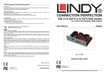
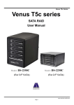
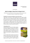
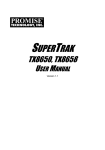
Venus T5
Venus T5
SATA RAID
User Manual
2009/07/16
Page 1
Venus T5
Contents
1. Features of ....................................................................................................................................................4
2. Introduction...................................................................................................................................................6
3. Getting Start..................................................................................................................................................8
3.1 Basic Mode...................................................................................................................................................8
3.1.1 RAID and Disk Information...................................................................................................................8
3.1.1.1 Controller Information.........................................................................................................................8
3.1.1.2 RAID Information...............................................................................................................................11
3.1.1.3 Disk Information..................................................................................................................................11
3.1.2 Event Log Viewer....................................................................................................................................13
3.1.3 Basic RAID Configuration.....................................................................................................................15
3.2 Advanced Mode..........................................................................................................................................19
3.2.1 Email Notification And Event Settings.................................................................................................19
3.2.2 Advanced RAID Configuration.............................................................................................................20
3.2.3 Firmware Information...........................................................................................................................25
4. DIP Switch and RAID Mode Cross Reference..........................................................................................28
Figures
Figure 1 – Tray Figure......................................................................................................................................4
Figure 2 – Appearance Figure..........................................................................................................................4
Figure 3 – Caddy Drive Drawer Install...........................................................................................................4
Figure 4 – Front Panel.......................................................................................................................................5
Figure 5 – Rear View.........................................................................................................................................5
Figure 6 – Functional Button............................................................................................................................6
Figure 7 – Basic Mode.......................................................................................................................................7
Figure 8 – Advanced Mode...............................................................................................................................7
Figure 9 – Controller Information...................................................................................................................9
Figure 10 – Identify The Controller...............................................................................................................10
Figure 11 – System Information.....................................................................................................................10
Figure 12 – RAID Information.......................................................................................................................11
Figure 13 – Disk Information.........................................................................................................................12
Figure 14 – SMART Information...................................................................................................................13
Figure 15 – Event Log Viewer........................................................................................................................14
Figure 16 – Save The Event Logs To A File...................................................................................................14
Figure 17 – Create RAID 10...........................................................................................................................15
Figure 18 – Setting Password for new RAID................................................................................................16
2009/07/16
Page 2
Venus T5
Figure 19 – Confirmation Dialog...................................................................................................................16
Figure 20 – Show Configuration Progress Window.....................................................................................17
Figure 21 – Information Message Box..........................................................................................................17
Figure 22 – Warning Message Box................................................................................................................18
Figure 23 – Update Disk Charts After Creating RAID...............................................................................18
Figure 24 – Update Disk Charts After Deleting All RAID..........................................................................19
Figure 25 – Email Notification and Event Settings......................................................................................20
Figure 26 – “Select All Events” Button and “Clear All Events” Button....................................................20
Figure 27 – Advanced RAID Configuration.................................................................................................21
Figure 28 – Advanced RAID Configuration.................................................................................................22
Figure 29 – Modify RAID Disk Size..............................................................................................................23
Figure 30 – Delete RAID................................................................................................................................24
Figure 31 – Select The Deleted RAID And Provide Password....................................................................25
Figure 32 – Firmware Update........................................................................................................................26
Figure 33 – Show Progress Bar......................................................................................................................27
Figure 34 – Show Dialog to Reboot The System...........................................................................................27
2009/07/16
Page 3
Venus T5
1. Features
z
z
z
z
z
z
z
z
z
z
z
z
z
z
Aluminum Frame, Aluminum cover
Interface support SATA-І, SATA-ІІ
High performance transfer rate up to 1.5Gbps, 3.0Gbps
Plug & play ,hot swappable
AC Power control
Easy RAID setting by DIP switch & apply (change mode) switch
LED indicators(for System Ready, HDD Error, HDD Access, Temperature, fan)
8x8cm Fan X 2— High/Low speed selectable
Reset switch or OTB switch for option
Color: BLACK
Dim:215(L)x156(W)x211(H)mm
Patent products with advanced structure design
Patent balance handle-no skew in/out problem and avoid the abrasion during connection
Precisely connection on connector (see Figure 1)
Figure 1
`
Figure 3
Figure 2
2009/07/16
Page 4
Venus T5
---Front Panel--- (see Figure 4)
D1:Temperature LED
D2:Fan LED
D3---D7: HDD Access and failure LED (Green LED
is lighting when HDD link and blinking
when HDD access; the LED will turn red
when HDD failed. The green LED and red
LED will alternate during rebuilding)
D8:SYS LED: Lighting while system is ready
D9:SYS Reset or Backup (option)
D10:HDD Safety Lock
D11:Power LED
D12:Power Safety Lock (The safety lock prevent
it bouncing out while HDD is working)
D13:120W Switching Power Supply
Figure 4
---Rear View--- (see Figure 5)
E1:Cooling Fan #1 (8x8cm)
E2:Fan Speed Control FAN RPM HIGH(3600rpm)&
LOW(2800 rpm) Options(If you want the fan to
run at a high speed ,switch to the right; otherwise
, switch to the left
E3: Cooling Fan #2 (8x8cm)
E4: Reset/Change Mode (push button less than 2
seconds for system reset / hold button over than
2 seconds for apply new RAID mode)
E5:RAID CONFIGURE SW
E6:ESATA
E7:Power SW
E8:Power Input(AC 100V-240V)
Figure 5
2009/07/16
Page 5
Venus T5
2. Introduction
This guide explains how to use JMB39X HW RAID Manager to configure RAID and monitor the status
of the disks connected on JMB39X hardware RAID controller.
Once JMB39X HW RAID Manager is launched, the JMB39X HW RAID Manager GUI window will be
opened and the application icon could also be found in the notification tray located at the bottom right
hand corner of the screen.
For the consideration of different user experiences and achieving the ease of navigation, the main GUI is
divided into two modes (“Basic mode” and “Advance mode”).
When the user presses the “Basic Mode” button on the right side of the GUI window, there are three
buttons to be chosen for navigating the corresponding basic pages. Those basic pages are “RAID and
Disk Information” page, “Event Log Viewer” page and “Basic RAID Configuration” page. Users could
simply do basic RAID configuration and browse all disks and RAID information as well as the event
logs in this basic mode.
For the advanced users, they could press the “Advanced Mode” button to invoke another three advanced
pages and do the advanced settings. Those advanced pages are “Email Notification and Event Settings”
page, ”Advanced RAID Configuration” page and “Firmware Update ” page.
Besides, there are some buttons appearing on the upper part of the GUI window and they are provided
for users to minimize the window, close the window, turn off the buzzer (if the buzzer exists), and open
the About Window.
Figure 6 – Functional Buttons
2009/07/16
Page 6
Venus T5
Figure7 – Basic Mode
Figure 8 – Advanced Mode
2009/07/16
Page 7
Venus T5
3. Getting Started
The following sections will lead you go through all basic pages and advanced pages. Let us start with
the “RAID and Disk Information” page.
3.1
Basic Mode
The basic mode is aimed to provide users to navigate the disk and RAID information, the event log as
well as do the basic configuration to the connected disks.
3.1.1 RAID and Disk Information
This page consists of two parts. The left part is a tree which shows all controllers on this platform and
their connected RAID and disks in a hierarchy view. When the user selects a tree item, the detail
information of the selected item will be displayed in the right part. All the disk and RAID information
will be updated in real–time and users could monitor the status easily.
3.1.1.1 Controller Information
If the user selects a controller item from the tree view, it will display the model name and capacity of the
RAID and disks connected on the specified controller at the right top table and also display all
connected disk charts at the right bottom area. For RAID member disks, the disk charts will be drawn
with the different colors according to the different RAID.
2009/07/16
Page 8
Venus T5
Figure 9 – Controller Information
When the user move the mouse upon the “Controller Information” label, it will be highlighted with red
color and show a tool-tip to tell that it could be clicked to identify the controller with the specified host
LED flashing.
2009/07/16
Page 9
Venus T5
Figure 10 – Identify the Controller
If the hardware monitor controller exists, the application will show an “Advanced…” label at the right
bottom corner of the table. The user could simply click it to browse the system information.
Figure 11 – System Information
2009/07/16
Page 10
Venus T5
3.1.1.2 RAID Information
If the user selects a RAID item from the tree view, it will display the detail information of the specified
RAID at the right top table and also display the RAID member disk charts at the right bottom area.
Figure12 – RAID Information
If the selected RAID is in rebuilding state, it will be highlighted with green color in the tree view. Also,
the rebuilding animation will be played at the bottom left and right area. The rebuilding percentage is
displayed at the bottom center area, too.
The user could simply click the “RAID Information” label to identify the member disks of the specified
RAID with all disk LED flashings at the same time.
2009/07/16
Page 11
Venus T5
3.1.1.3 Disk Information
If the user selects a Disk item from the tree view, it will display the detail information of the specified
disk at the right top table and also display the disk pie chart at the right bottom area.
If the selected disk is one member disk of the rebuilding RAID, the rebuilding animation will also be
played at the bottom left and right area. The rebuilding percentage is displayed at the bottom center area,
too.
Figure 13 – Disk Information
The user could simply click the “Disk Information” label to identify the specified RAID with the disk
LED flashing.
2009/07/16
Page 12
Venus T5
If the disk is a RAID member disk, the application will show an “Advanced…” label at the right bottom
corner of the table. The user could simply click it to browse the SMART information of the specified
disk.
Figure 14 – SMART Information
3.1.2 Event Log Viewer
JMicron HW RAID Manager will monitor the status of all connected disks and RAID and make records
of the occurrence of the events. The user could browse all events through this event log viewer page.
The user could save the logs to a profile by pressing the “Save to Profile” button. It will pop up a dialog
for the user to fill the profile name.
Besides, the user could simply clear all the logs by pressing the “Clear” button.
2009/07/16
Page 13
Venus T5
Figure 15 – Event Log Viewer
Figure 16 – Save The Event Logs To A File
2009/07/16
Page 14
Venus T5
3.1.3 Basic RAID Configuration
JMicron HW RAID Manager provides users to do the basic RAID configuration to the connected disks
in this page. According to the number and capacity of the connected disks, JMicron HW RAID Manager
will provide the available RAID type for users to select. When the user select his/her desired RAID type,
JMicron HW RAID Manager will automatically select the available disks to build the RAID and
calculate the RAID capacity. It will show the selected disks charts drawn in the cross pattern on the right
part.
For example, if the user selects RAID 10, JMicron HW RAID Manager will select four available disks
to build RAID 10 starting from the lower Disk number. At the mean while, it will calculate the smallest
disk size to build RAID and calculate the total capacity of the RAID.
Figure 17 – Create RAID 10
If the user wants to set the password for the new RAID, he/she could check the password group box and
enter the password.
2009/07/16
Page 15
Venus T5
Figure 18 – Setting Password for new RAID
After selecting the RAID type and setting the password (optional), the user just need press the “Apply”
button to apply the configuration or press “Cancel” button to restore to the original disk state.
If the user wants to delete the existing RAID, the user could select the “DELETE ALL RAID” button to
delete the RAID and apply it.
When the user presses the “Apply” button, it will pop up a dialog to ask for the confirmation.
Figure 19 – Confirmation Dialog
After the user confirms to apply the configuration, it will pop up another progress window to show the
configuration status.
2009/07/16
Page 16
Venus T5
Figure 20 – Show Configuration Progress Window
After the RAID configuration finishes, it will pop up a message dialog to tell that a RAID is newly
created or a RAID has been deleted.
Figure 21 – Information Message Box
2009/07/16
Page 17
Venus T5
Figure 22 – Warning Message Box
At last, the disk charts will be redrawn to reflect the result of the configuration. The newly created RAID
will be shown with the gradient color. If the user deletes the RAID, the disk charts will be drawn in
green color.
Figure 23 – Update Disk Charts after Creating RAID
2009/07/16
Page 18
Venus T5
Figure 24 – Update Disk Charts after Deleting All RAID
3.2
Advanced Mode
The advanced mode is aimed to provide the advanced functionalities, such as Email notification settings,
the advanced RAID configuration and firmware update.
3.2.1 Email Notification and Event Settings
JMicron HW RAID Manager provides the function of the email notification when the specified events
occur. The user might enter the mail server name, mail server port, sender e-mail address and recipients’
e-mail addresses in this page. If the specified mail server need authenticate the sender’s password when
sending mail, the user might enter the correct username and password.
To check if the entered data is correct or not, the user could simply click the “Send Mail Test” button to
send a mail to the specified recipients for testing.
2009/07/16
Page 19
Venus T5
Figure 25 – Email Notification and Event Settings
Additionally, the user might select the events for email notification. The user could click the following
buttons to select all events or clear all events. Of course, he could also check the events by himself for
e-mail notification.
Figure 26 – “Select All Events” Button and “Clear All Events” Button
Furthermore, the user could save the email and event settings to a profile by pressing the “Save To
Profile” button or load the settings from the specified profile by pressing “Load From Profile” button.
At last, the user could press the “Apply” button to apply the specified email and event settings or press
the “Cancel” button to restore to the original settings.
3.2.2 Advanced RAID Configuration
For the advanced users, JMicron HW RAID Manager also provides them to do the advanced RAID
configuration to the connected disks.
The user is not only able to select the RAID type but also could select the desirable disks to build the
2009/07/16
Page 20
Venus T5
RAID. JMicron HW RAID Manager will depend on the status of the connected disks and provide the
available disks for users to select.
Figure 27 – Advanced RAID Configuration (Select Disks and Enter Password)
After applying the RAID configuration, the disk charts are updated and the supported RAID type will
also be updated according to the remaining of the available disks.
2009/07/16
Page 21
Venus T5
Figure 28 – Advanced RAID Configuration
When the user selects the disks, he/she could also modify the RAID disk size by simply clicking the
specified disk chart and adjust the disk size from the slider at the bottom. The disk which is being adjusted
the size is highlighted with deep red color.
2009/07/16
Page 22
Venus T5
Figure 29 – Modify RAID Disk Size
The user could delete the RAID by checking the “Delete DAID” check box. The bottom group box will
be updated and show the existing RAID. The user could select the RAID to be deleted.
2009/07/16
Page 23
Venus T5
Figure 30 – Delete RAID
If the deleted RAID supports password, the password check box will be automatically enabled for the
user to enter the password.
The RAID member disk which is being deleted is drawn in the cross pattern.
The “Apply” button is just enabled for clicking once all configuration settings are done.
2009/07/16
Page 24
Venus T5
Figure 31 – Select The Deleted RAID And Provide Password
3.2.3 Firmware Information
The user could browse the firmware information and update the firmware in this page.
To update the firmware, the user just simply presses the “browse” button to select the suitable firmware
and then presses the “Update” button.
2009/07/16
Page 25
Venus T5
Figure 32 – Firmware Update
There is a progress bar to be appeared at the bottom and it will show the percentage of the firmware
update.
After the firmware update progress finishes, it will popup a message dialog and ask the user to restart
the controller to take effect.
2009/07/16
Page 26
Venus T5
Figure 33 – Show Progress Bar
Figure 34 – Show Dialog to Reboot the System
2009/07/16
Page 27
Venus T5
4. DIP Switch and RAID Mode cross reference
User can configure any RAID mode as below by DIP switch and apply change by Change Mode button.
RAID Mode
Dip Switch
1
2
3
RAID 0
ON
ON
ON
RAID 10
ON
ON
OFF
JBOD (Large)
ON
OFF
ON
RAID 3
ON
OFF
OFF
Clone
OFF
ON
ON
RAID 5
OFF
ON
OFF
Reserved
OFF
OFF
ON
Normal (Single)
OFF
OFF
OFF
*PS: When DIP-SW is RAID10, 2 HDDs is RAID1 Mode and 4 HDDs is RAID10 Mode.
4.1 RAID 0 for High Performance
RAID 0(or Stripe) is the segmentation of logically sequential data, such as a single file, so that segments
can be assigned to multiple hard disks in a round-robin fashion and thus written concurrently. (If any hard
disk becomes defective, information stored in this RAID0 will be invalid.)
2009/07/16
Page 28
Venus T5
4.2 RAID 1 (Mirror) for High Security
Mirror or RAID 1 is the replication of data onto separate hard disks in real time to ensure continuous
availability. Take a RAID 1 system with two hard disks as an example, data in a hard disk will be exactly
the same as the data in another hard disk.
(Failure in a hard disk, Host controller still could read/write data. Users have to replace the defect hard disk.
T5 will enter on-line-auto-rebuild mode automatically)
4.3 Stripe + Mirror (RAID 10) for High Performance and High Security
T5 could be configured to support Stripe and Mirror at the same time, i.e. RAID 10. Take four hard drives
RAID 10 as an example. Hard drive 0 and hard drive 1 could act as Mirror 1. Hard drive 2 and hard drive 3
could act as Mirror 1 too. 2350ESR then configure these two Mirrors as Stripe.
2009/07/16
Page 29
Venus T5
4.4 Clone
The action of Clone is similar to RAID 1. However, all of the hard disks will be the mirrors. For example,
in a four hard drives Clone environment, data in each hard drive will be same. This mode is useful
especially when users would like to copy data from a hard drive to several hard drives at the same time.
4.5 JBOD (Concatenating)
This mode is also named Concatenating. In this mode, T5 will concatenate all of the hard drives into a
single hard drive with larger capacity. For example, if three 500GB hard disks is connected to T5 in
concatenating mode, user will get a single hard disk with capacity of 1,500 GB.
2009/07/16
Page 30
Venus T5
4.6 Parity Protection
XOR engine in T5 generate parity block. In RAID 3 mode, Parity Block will be stored in the same hard
drive. While in RAID 5 mode, Parity Block will be spread over all of the different hard drives.
T5 will also make use of same size disk space in each hard disk under RAID 3/5 condition. ( Failure
in a hard disk will cause T5 enter degrade mode. Host controller still could read/write data thru T5
normally without knowing any defects. Users have to replace the defective hard disk. T5 then will enter
on-line-auto-rebuild mode automatically.)
1.7 Normal Mode (Single)
Normal mode means all of the configured hard drives exist and T5 is not in rebuild condition. User can see
the original hard drives from the host which supports port multiplier technology. (If the host does not
support port multiplier, then you will find only one hard drive on operating system. The RAID tool is
useful in this case.)
2009/07/16
Page 31