1
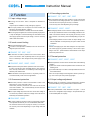
Ordering information
Unit type
PBA
PBA50F
PBA
1
50
2
F
3
-5
4
-O
5
1Series name
2Output wattage
3Universal input
4Output voltage
5Optional
C :with Coating
G :Low leakage current
(0.15mA max / ACIN 240V)
E :Low leakage current
and EMI class A
(0.5mA max / ACIN 240V)
T :Vertical terminal block
J :Connector type
R :with Remote ON/OFF
N :with Cover
(Only 24V UL508 is acquired)
N1 :with DIN rail
V :Output voltage setting
potentiometer externally
R
Specification is changed at
option. Please consult us
details.
MODEL
MAX OUTPUT WATTAGE[W]
DC OUTPUT
PBA50F-3R3
33
3.3V 10A
PBA50F-5
50
5V 10A
PBA50F-9
50.4
9V 5.6A
PBA50F-12
51.6
12V 4.3A
PBA50F-15
52.5
15V 3.5A
PBA50F-24
52.8
24V 2.2A
PBA50F-36
50.4
36V 1.4A
PBA50F-48
52.8
48V 1.1A
PBA50F-3R3 PBA50F-5
PBA50F-9
PBA50F-12
PBA50F-15
PBA50F-24
PBA50F-36
AC85 - 264 1f or DC120 - 370 (AC50 or DC70 optionally available *4)
0.5typ
0.7typ
0.3typ
0.4typ
50/60 (47 - 63)
75typ
80typ
79typ
80typ
81typ
82typ
83typ
76typ
82typ
81typ
82typ
83typ
84typ
85typ
0.98typ
0.99typ
0.87typ
0.93typ
15typ (Io=100%) (At cold start)
30typ (Io=100%) (At cold start)
0.4/0.75max (ACIN 100V/240V 60Hz, Io=100%, According to IEC60950-1)
3.3
5
9
12
15
24
36
10
10
5.6
4.3
3.5
2.2
1.4
20max
20max
36max
48max
60max
96max
144max
40max
40max
100max
100max
120max
150max
240max
80max
80max
120max
120max
120max
120max
150max
140max
140max
160max
160max
160max
160max
200max
120max
120max
150max
150max
150max
150max
250max
160max
160max
180max
180max
180max
180max
300max
50max
50max
90max
120max
150max
240max
360max
60max
60max
120max
150max
180max
290max
450max
20max
20max
36max
48max
60max
96max
144max
350typ(ACIN 100V, Io=100%)
20typ (ACIN 100V, Io=100%)
2.85 - 3.63
4.00 - 5.50
7.50 - 10.0
10.0 - 13.2
13.2 - 18.0
19.2 - 27.0
28.8 - 39.6
3.20 - 3.40
4.90 - 5.20
8.70 - 9.30
11.5 - 12.5
14.5 - 15.5
23.5 - 24.5
35.5 - 36.5
Works over 105% of rated current and recovers automatically
4.00 - 5.25
5.75 - 7.00
11.5 - 14.0
15.0 - 18.0
20.0 - 25.0
30.0 - 37.0
43.0 - 50.0
LED (Green)
Optional (Required external power source)
AC3,000V 1minute, Cutoff current = 10mA, DC500V 50MWmin (At Room Temperature)
AC2,000V 1minute, Cutoff current = 10mA, DC500V 50MWmin (At Room Temperature)
AC500V 1minute, Cutoff current = 100mA, DC500V 50MWmin (At Room Temperature)
-10 to +71C (Required Derating), 20 - 90%RH (Non condensing) 3,000m (10,000feet) max
-20 to +75C, 20 - 90%RH (Non condensing) 3,000m (10,000feet) max
19.6m/s2 (2G), 10 - 55Hz, 3minutes period, 60minutes each along X, Y and Z axis
196.1m/s2 (20G), 11ms, once each X, Y and Z axis
UL60950-1, C-UL(CSA60950-1), EN60950-1, EN50178 Complies with DEN-AN (At only AC input)
Complies with FCC Part15 classB, VCCI-B, CISPR22-B, EN55011-B, EN55022-B
Low Voltage Directive, EMC Directive
Complies with IEC61000-3-2
31X82X120mm (without terminal block) (WXHXD) / 280g max (without cover)
Convection
PBA50F-48
SPECIFICATIONS
MODEL
VOLTAGE[V]
CURRENT[A]
ACIN 100V
ACIN 200V
FREQUENCY[Hz]
INPUT
OUTPUT
PROTECTION
CIRCUIT AND
OTHERS
ISOLATION
ENVIRONMENT
SAFETY AND
NOISE
REGULATIONS
OTHERS
ACIN 100V
ACIN 200V
ACIN 100V
(
)
POWER FACTOR Io=100%
ACIN 200V
ACIN 100V
INRUSH CURRENT[A]
ACIN 200V
LEAKAGE CURRENT[mA]
VOLTAGE[V]
CURRENT[A]
LINE REGULATION[mV]
LOAD REGULATION[mV]
0 to +50C *1
RIPPLE[mVp-p]
-10 - 0C *1
0 to +50C *1
RIPPLE NOISE[mVp-p]
-10 - 0C *1
0 to +50C
TEMPERATURE REGULATION[mV]
-10 to +50C
DRIFT[mV]
*2
START-UP TIME[ms]
HOLD-UP TIME[ms]
OUTPUT VOLTAGE ADJUSTMENT RANGE[V]
OUTPUT VOLTAGE SETTING[V]
OVERCURRENT PROTECTION
OVERVOLTAGE PROTECTION[V]
OPERATING INDICATION
REMOTE ON/OFF
INPUT-OUTPUT -RC
*3
INPUT-FG
OUTPUT-RC-FG
*3
OPERATING TEMP.,HUMID.AND ALTITUDE
STORAGE TEMP.,HUMID.AND ALTITUDE
VIBRATION
IMPACT
AGENCY APPROVALS
CONDUCTED NOISE
CE MARKING
HARMONIC ATTENUATOR
CASE SIZE/WEIGHT
COOLING METHOD
EFFICIENCY[%]
*1 Measured by 20MHz oscilloscope or Ripple-Noise meter(equivalent to KEISOKU-GIKEN :
RM101).
*2 Drift is the change in DC output for an eight hour period after a half-hour warm-up at 25C.
*3 Applicable when Remote ON/OFF(optional) is added. RC is insulated with input, output and
FG.
*4 Derating is required.Consult us for details.
A-4
*
*
*
Parallel operation with other model is not possible.
Derating is required when operated with cover.
A sound may occur from power supply at peak loading.
83typ
85typ
48
1.1
192max
240max
150max
200max
250max
300max
480max
600max
192max
39.0 - 53.0
47.0 - 49.0
58.0 - 65.0
Ordering information
Unit type
PBA
PBA75F
PBA
1
75
2
F
3
-5
4
-O
5
1Series name
2Output wattage
3Universal input
4Output voltage
5Optional
C :with Coating
G :Low leakage current
(0.15mA max / ACIN 240V)
E :Low leakage current
and EMI class A
(0.5mA max / ACIN 240V)
T :Vertical terminal block
J :Connector type
R :with Remote ON/OFF
N :with Cover
(Only 24V UL508 is acquired)
N1: with DIN rail
V :Output voltage setting
potentiometer externally
R
Specification is changed at
option. Please consult us
details.
MODEL
MAX OUTPUT WATTAGE[W]
DC OUTPUT
PBA75F-3R3
49.5
3.3V 15A
PBA75F-5
75
5V 15A
PBA75F-9
75.6
9V 8.4A
PBA75F-12
75.6
12V 6.3A
PBA75F-15
75
15V 5A
PBA75F-24
76.8
24V 3.2A
PBA75F-36
75.6
36V 2.1A
PBA75F-48
76.8
48V 1.6A
PBA75F-3R3 PBA75F-5
PBA75F-9
PBA75F-12
PBA75F-15
PBA75F-24
PBA75F-36
AC85 - 264 1f or DC120 - 370 (AC50 or DC70 optionally available *4)
0.7typ
1.0typ
0.4typ
0.5typ
50/60 (47 - 63)
77typ
81typ
80typ
81typ
82typ
83typ
84typ
78typ
83typ
82typ
83typ
84typ
85typ
86typ
0.98typ
0.99typ
0.87typ
0.93typ
15typ (Io=100%) (At cold start)
30typ (Io=100%) (At cold start)
0.4/0.75max (ACIN 100V/240V 60Hz, Io=100%, According to IEC60950-1)
3.3
5
9
12
15
24
36
15
15
8.4
6.3
5
3.2
2.1
20max
20max
36max
48max
60max
96max
144max
40max
40max
100max
100max
120max
150max
240max
80max
80max
120max
120max
120max
120max
150max
140max
140max
160max
160max
160max
160max
200max
120max
120max
150max
150max
150max
150max
250max
160max
160max
180max
180max
180max
180max
300max
50max
50max
90max
120max
150max
240max
360max
60max
60max
120max
150max
180max
290max
450max
20max
20max
36max
48max
60max
96max
144max
350typ(ACIN 100V, Io=100%)
20typ (ACIN 100V, Io=100%)
2.85 - 3.63
4.00 - 5.50
7.50 - 10.0
10.0 - 13.2
13.2 - 18.0
19.2 - 27.0
28.8 - 39.6
3.20 - 3.40
4.90 - 5.20
8.70 - 9.30
11.5 - 12.5
14.5 - 15.5
23.5 - 24.5
35.5 - 36.5
Works over 105% of rated current and recovers automatically
4.00 - 5.25
5.75 - 7.00
11.5 - 14.0
15.0 - 18.0
20.0 - 25.0
30.0 - 37.0
43.0 - 50.0
LED (Green)
Optional (Required external power source)
AC3,000V 1minute, Cutoff current = 10mA, DC500V 50MWmin (At Room Temperature)
AC2,000V 1minute, Cutoff current = 10mA, DC500V 50MWmin (At Room Temperature)
AC500V 1minute, Cutoff current = 100mA, DC500V 50MWmin (At Room Temperature)
-10 to +71C (Required Derating), 20 - 90%RH (Non condensing) 3,000m (10,000feet) max
-20 to +75C, 20 - 90%RH (Non condensing) 3,000m (10,000feet) max
19.6m/s2 (2G), 10 - 55Hz, 3minutes period, 60minutes each along X, Y and Z axis
196.1m/s2 (20G), 11ms, once each X, Y and Z axis
UL60950-1, C-UL(CSA60950-1), EN60950-1, EN50178 Complies with DEN-AN (At only AC input)
Complies with FCC Part15 classB, VCCI-B, CISPR22-B, EN55011-B, EN55022-B
Low Voltage Directive, EMC Directive
Complies with IEC61000-3-2
32X82X135mm (without terminal block) (WXHXD) / 350g max (without cover)
Convection
PBA75F-48
SPECIFICATIONS
MODEL
VOLTAGE[V]
CURRENT[A]
ACIN 100V
ACIN 200V
FREQUENCY[Hz]
INPUT
OUTPUT
PROTECTION
CIRCUIT AND
OTHERS
ISOLATION
ENVIRONMENT
SAFETY AND
NOISE
REGULATIONS
OTHERS
ACIN 100V
ACIN 200V
ACIN 100V
(
)
POWER FACTOR Io=100%
ACIN 200V
ACIN 100V
INRUSH CURRENT[A]
ACIN 200V
LEAKAGE CURRENT[mA]
VOLTAGE[V]
CURRENT[A]
LINE REGULATION[mV]
LOAD REGULATION[mV]
0 to +50C *1
RIPPLE[mVp-p]
-10 - 0C *1
0 to +50C *1
RIPPLE NOISE[mVp-p]
-10 - 0C *1
0 to +50C
TEMPERATURE REGULATION[mV]
-10 to +50C
DRIFT[mV]
*2
START-UP TIME[ms]
HOLD-UP TIME[ms]
OUTPUT VOLTAGE ADJUSTMENT RANGE[V]
OUTPUT VOLTAGE SETTING[V]
OVERCURRENT PROTECTION
OVERVOLTAGE PROTECTION[V]
OPERATING INDICATION
REMOTE ON/OFF
INPUT-OUTPUT -RC
*3
INPUT-FG
OUTPUT-RC-FG
*3
OPERATING TEMP.,HUMID.AND ALTITUDE
STORAGE TEMP.,HUMID.AND ALTITUDE
VIBRATION
IMPACT
AGENCY APPROVALS
CONDUCTED NOISE
CE MARKING
HARMONIC ATTENUATOR
CASE SIZE/WEIGHT
COOLING METHOD
EFFICIENCY[%]
*1 Measured by 20MHz oscilloscope or Ripple-Noise meter(equivalent to KEISOKU-GIKEN :
RM101).
*2 Drift is the change in DC output for an eight hour period after a half-hour warm-up at 25C.
*3 Applicable when Remote ON/OFF(optional) is added. RC is insulated with input, output and
FG.
*4 Derating is required.Consult us for details.
A-6
*
*
*
Parallel operation with other model is not possible.
Derating is required when operated with cover.
A sound may occur from power supply at peak loading.
84typ
86typ
48
1.6
192max
240max
150max
200max
250max
300max
480max
600max
192max
39.0 - 53.0
47.0 - 49.0
58.0 - 65.0
Ordering information
Unit type
PBA
PBA100F
PBA 100
1
2
F
3
-5
4
-O
5
1Series name
2Output wattage
3Universal input
4Output voltage
5Optional
C :with Coating
G :Low leakage current
(0.15mA max / ACIN 240V)
E :Low leakage current
and EMI class A
(0.5mA max / ACIN 240V)
T :Vertical terminal block
J :Connector type
(Only -12,-15,-24,-36,-48)
R :with Remote ON/OFF
N :with Cover
(Only 24V UL508 is acquired)
N1 :with DIN rail
V :Output voltage setting
potentiometer externally
R
Specification is changed at
option. Please consult us
details.
MODEL
MAX OUTPUT WATTAGE[W]
DC OUTPUT
PBA100F-3R3 PBA100F-5
66
100
3.3V 20A
5V 20A
PBA100F-9
94.5
9V 10.5A
PBA100F-12
102
12V 8.5A
PBA100F-15
105
15V 7A
PBA100F-24
108
24V 4.5A
PBA100F-36
100.8
36V 2.8A
PBA100F-48
100.8
48V 2.1A
PBA100F-3R3 PBA100F-5
PBA100F-9
PBA100F-12 PBA100F-15 PBA100F-24 PBA100F-36
AC85 - 264 1f or DC120 - 370 (AC50 or DC70 optionally available *4)
0.9typ
1.3typ
0.5typ
0.7typ
50/60 (47 - 63)
77typ
82typ
80typ
81typ
83typ
84typ
84typ
79typ
84typ
82typ
83typ
86typ
86typ
86typ
0.98typ
0.99typ
0.87typ
0.93typ
20typ (Io=100%) (At cold start)
40typ (Io=100%) (At cold start)
0.4/0.75max (ACIN 100V/240V 60Hz, Io=100%, According to IEC60950-1)
3.3
5
9
12
15
24
36
20
20
10.5
8.5
7
4.5
2.8
20max
20max
36max
48max
60max
96max
144max
40max
40max
100max
100max
120max
150max
240max
80max
80max
120max
120max
120max
120max
150max
140max
140max
160max
160max
160max
160max
200max
120max
120max
150max
150max
150max
150max
250max
160max
160max
180max
180max
180max
180max
300max
50max
50max
90max
120max
150max
240max
360max
60max
60max
120max
150max
180max
290max
450max
20max
20max
36max
48max
60max
96max
144max
350typ(ACIN 100V, Io=100%)
20typ (ACIN 100V, Io=100%)
2.85 - 3.63
4.00 - 5.50
7.50 - 10.0
10.0 - 13.2
13.2 - 18.0
19.2 - 27.0
28.8 - 39.6
3.20 - 3.40
4.90 - 5.20
8.70 - 9.30
11.5 - 12.5
14.5 - 15.5
23.5 - 24.5
35.5 - 36.5
Works over 105% of rated current and recovers automatically
4.00 - 5.25
5.75 - 7.00
11.5 - 14.0
15.0 - 18.0
20.0 - 25.0
30.0 - 37.0
43.0 - 50.0
LED (Green)
Optional (Only -3R3, -5 Option -K)
Optional (Required external power source)
AC3,000V 1minute, Cutoff current = 10mA, DC500V 50MWmin (At Room Temperature)
AC2,000V 1minute, Cutoff current = 10mA, DC500V 50MWmin (At Room Temperature)
AC500V 1minute, Cutoff current = 100mA, DC500V 50MWmin (At Room Temperature)
-10 to +71C (Required Derating), 20 - 90%RH (Non condensing) 3,000m (10,000feet) max
-20 to +75C, 20 - 90%RH (Non condensing) 3,000m (10,000feet) max
19.6m/s2 (2G), 10 - 55Hz, 3minutes period, 60minutes each along X, Y and Z axis
196.1m/s2 (20G), 11ms, once each X, Y and Z axis
UL60950-1, C-UL(CSA60950-1), EN60950-1, EN50178 Complies with DEN-AN (At only AC input)
Complies with FCC Part15 classB, VCCI-B, CISPR22-B, EN55011-B, EN55022-B
Low Voltage Directive, EMC Directive
Complies with IEC61000-3-2
32X93X147mm (without terminal block) (WXHXD) / 440g max (without cover)
Convection
PBA100F-48
SPECIFICATIONS
MODEL
VOLTAGE[V]
CURRENT[A]
ACIN 100V
ACIN 200V
FREQUENCY[Hz]
INPUT
OUTPUT
PROTECTION
CIRCUIT AND
OTHERS
ISOLATION
ENVIRONMENT
SAFETY AND
NOISE
REGULATIONS
OTHERS
ACIN 100V
ACIN 200V
ACIN 100V
POWER FACTOR(Io=100%)
ACIN 200V
ACIN 100V
INRUSH CURRENT[A]
ACIN 200V
LEAKAGE CURRENT[mA]
VOLTAGE[V]
CURRENT[A]
LINE REGULATION[mV]
LOAD REGULATION[mV]
0 to +50C *1
RIPPLE[mVp-p]
-10 - 0C *1
0 to +50C *1
RIPPLE NOISE[mVp-p]
-10 - 0C *1
0 to +50C
TEMPERATURE REGULATION[mV]
-10 to +50C
DRIFT[mV]
*2
START-UP TIME[ms]
HOLD-UP TIME[ms]
OUTPUT VOLTAGE ADJUSTMENT RANGE[V]
OUTPUT VOLTAGE SETTING[V]
OVERCURRENT PROTECTION
OVERVOLTAGE PROTECTION[V]
OPERATING INDICATION
REMOTE SENSING
REMOTE ON/OFF
INPUT-OUTPUT -RC
*3
INPUT-FG
OUTPUT-RC-FG
*3
OPERATING TEMP.,HUMID.AND ALTITUDE
STORAGE TEMP.,HUMID.AND ALTITUDE
VIBRATION
IMPACT
AGENCY APPROVALS
CONDUCTED NOISE
CE MARKING
HARMONIC ATTENUATOR
CASE SIZE/WEIGHT
COOLING METHOD
EFFICIENCY[%]
*1 Measured by 20MHz oscilloscope or Ripple-Noise meter(equivalent to KEISOKU-GIKEN :
RM101).
*2 Drift is the change in DC output for an eight hour period after a half-hour warm-up at 25C.
*3 Applicable when Remote ON/OFF(optional) is added. RC is insulated with input, output and
FG.
*4 Derating is required.Consult us for details.
A-8
*
*
*
Parallel operation with other model is not possible.
Derating is required when operated with cover.
A sound may occur from power supply at peak loading.
84typ
86typ
48
2.1
192max
240max
150max
200max
250max
300max
480max
600max
192max
39.0 - 53.0
47.0 - 49.0
58.0 - 65.0
Ordering information
Unit type
PBA
PBA150F
PBA 150
1
2
F
3
-5
4
-O
5
1Series name
2Output wattage
3Universal input
4Output voltage
5Optional
C :with Coating
G :Low leakage current
(0.15mA max / ACIN 240V)
E :Low leakage current
and EMI class A
(0.5mA max / ACIN 240V)
T :Vertical terminal block
J :Connector type
(Only -12,-15,-24,-36,-48)
R :with Remote ON/OFF
N :with Cover
(Only 24V UL508 is acquired)
N1 :with DIN rail
V :Output voltage setting
potentiometer externally
R
Specification is changed at
option. Please consult us
details.
MODEL
MAX OUTPUT WATTAGE[W]
DC OUTPUT
PBA150F-3R3 PBA150F-5
99
150
3.3V 30A
5V 30A
PBA150F-9
150.3
9V 16.7A
PBA150F-12
156
12V 13A
PBA150F-15
150
15V 10A
PBA150F-24
156
24V 6.5A
PBA150F-36
154.8
36V 4.3A
PBA150F-48
158.4
48V 3.3A
PBA150F-3R3 PBA150F-5
PBA150F-9
PBA150F-12 PBA150F-15 PBA150F-24 PBA150F-36
AC85 - 264 1f or DC120 - 370 (AC50 or DC70 optionally available *4)
1.3typ
2.0typ
0.7typ
1.0typ
50/60 (47 - 63)
80typ
83typ
82typ
83typ
84typ
85typ
85typ
82typ
86typ
85typ
86typ
87typ
88typ
88typ
0.98typ
0.99typ
0.87typ
0.93typ
20typ (Io=100%) (At cold start)
40typ (Io=100%) (At cold start)
0.4/0.75max (ACIN 100V/240V 60Hz, Io=100%, According to IEC60950-1)
3.3
5
9
12
15
24
36
30
30
16.7
13
10
6.5
4.3
20max
20max
36max
48max
60max
96max
144max
40max
40max
100max
100max
120max
150max
240max
80max
80max
120max
120max
120max
120max
150max
140max
140max
160max
160max
160max
160max
200max
120max
120max
150max
150max
150max
150max
250max
160max
160max
180max
180max
180max
180max
300max
50max
50max
90max
120max
150max
240max
360max
60max
60max
120max
150max
180max
290max
450max
20max
20max
36max
48max
60max
96max
144max
350typ(ACIN 100V, Io=100%)
20typ (ACIN 100V, Io=100%)
2.85 - 3.63
4.00 - 5.50
7.50 - 10.0
10.0 - 13.2
13.2 - 18.0
19.2 - 27.0
28.8 - 39.6
3.20 - 3.40
4.90 - 5.20
8.70 - 9.30
11.5 - 12.5
14.5 - 15.5
23.5 - 24.5
35.5 - 36.5
Works over 105% of rated current and recovers automatically
4.00 - 5.25
5.75 - 7.00
11.5 - 14.0
15.0 - 18.0
20.0 - 25.0
30.0 - 37.0
43.0 - 50.0
LED (Green)
Optional (Only -3R3, -5 Option -K)
Optional (Required external power source)
AC3,000V 1minute, Cutoff current = 10mA, DC500V 50MWmin (At Room Temperature)
AC2,000V 1minute, Cutoff current = 10mA, DC500V 50MWmin (At Room Temperature)
AC500V 1minute, Cutoff current = 100mA, DC500V 50MWmin (At Room Temperature)
-10 to +71C (Required Derating), 20 - 90%RH (Non condensing) 3,000m (10,000feet) max
-20 to +75C, 20 - 90%RH (Non condensing) 3,000m (10,000feet) max
19.6m/s2 (2G), 10 - 55Hz, 3minutes period, 60minutes each along X, Y and Z axis
196.1m/s2 (20G), 11ms, once each X, Y and Z axis
UL60950-1, C-UL(CSA60950-1), EN60950-1, EN50178 Complies with DEN-AN (At only AC input)
Complies with FCC Part15 classB, VCCI-B, CISPR22-B, EN55011-B, EN55022-B
Low Voltage Directive, EMC Directive
Complies with IEC61000-3-2
34X93X168mm (without terminal block) (WXHXD) / 560g max (without cover)
Convection
PBA150F-48
SPECIFICATIONS
MODEL
VOLTAGE[V]
CURRENT[A]
ACIN 100V
ACIN 200V
FREQUENCY[Hz]
INPUT
OUTPUT
PROTECTION
CIRCUIT AND
OTHERS
ISOLATION
ENVIRONMENT
SAFETY AND
NOISE
REGULATIONS
OTHERS
ACIN 100V
ACIN 200V
ACIN 100V
POWER FACTOR(Io=100%)
ACIN 200V
ACIN 100V
INRUSH CURRENT[A]
ACIN 200V
LEAKAGE CURRENT[mA]
VOLTAGE[V]
CURRENT[A]
LINE REGULATION[mV]
LOAD REGULATION[mV]
0 to +50C *1
RIPPLE[mVp-p]
-10 - 0C *1
0 to +50C *1
RIPPLE NOISE[mVp-p]
-10 - 0C *1
0 to +50C
TEMPERATURE REGULATION[mV]
-10 to +50C
DRIFT[mV]
*2
START-UP TIME[ms]
HOLD-UP TIME[ms]
OUTPUT VOLTAGE ADJUSTMENT RANGE[V]
OUTPUT VOLTAGE SETTING[V]
OVERCURRENT PROTECTION
OVERVOLTAGE PROTECTION[V]
OPERATING INDICATION
REMOTE SENSING
REMOTE ON/OFF
INPUT-OUTPUT -RC
*3
INPUT-FG
OUTPUT-RC-FG
*3
OPERATING TEMP.,HUMID.AND ALTITUDE
STORAGE TEMP.,HUMID.AND ALTITUDE
VIBRATION
IMPACT
AGENCY APPROVALS
CONDUCTED NOISE
CE MARKING
HARMONIC ATTENUATOR
CASE SIZE/WEIGHT
COOLING METHOD
EFFICIENCY[%]
*1 Measured by 20MHz oscilloscope or Ripple-Noise meter(equivalent to KEISOKU-GIKEN :
RM101).
*2 Drift is the change in DC output for an eight hour period after a half-hour warm-up at 25C.
*3 Applicable when Remote ON/OFF(optional) is added. RC is insulated with input, output and
FG.
*4 Derating is required.Consult us for details.
A-10
*
*
*
Parallel operation with other model is not possible.
Derating is required when operated with cover.
A sound may occur from power supply at peak loading.
85typ
88typ
48
3.3
192max
240max
150max
200max
250max
300max
480max
600max
192max
39.0 - 53.0
47.0 - 49.0
58.0 - 65.0
Ordering information
Unit type
PBA
PBA600F
PBA 600
1
2
F
3
-5
4
-O
5
1Series name
2Output wattage
3Universal input
4Output voltage
5Optional
C :with Coating
G :Low leakage current
U :Operation stop voltage
is set at a lower value
F1 :With Long-Life fan
F3 :Reverse air exhaust
type
F4 :Low speed fan
R
Refer to instruction manual
7.1
MODEL
MAX OUTPUT WATTAGE[W]
DC OUTPUT
PBA600F-3R3
396
ACIN 100V 3.3V 120A
ACIN 200V *3 3.3V 120A
PBA600F-5
600
5V 120A
5V 120A
PBA600F-7R5
600
7.5V 80A
7.5V 80A
PBA600F-12
636
12V 53A
12V 53A
PBA600F-15
645
15V 43A
15V 43A
PBA600F-24
648
24V 27A
24V 27(31)A
PBA600F-36
648
36V 18A
36V 18A
PBA600F-48
624
48V 13A
48V 13A
SPECIFICATIONS
MODEL
VOLTAGE[V]
CURRENT[A]
ACIN 100V
ACIN 200V
FREQUENCY[Hz]
INPUT
OUTPUT
PROTECTION
CIRCUIT AND
OTHERS
ISOLATION
ENVIRONMENT
SAFETY AND
NOISE
REGULATIONS
OTHERS
*1
*2
*3
*4
*5
*
ACIN 100V
ACIN 200V
ACIN 100V
POWER FACTOR
ACIN 200V
ACIN 100V
INRUSH CURRENT[A]
ACIN 200V
LEAKAGE CURRENT[mA]
VOLTAGE[V]
ACIN 100V
CURRENT[A]
ACIN 200V *3
LINE REGULATION[mV]
LOAD REGULATION[mV]
0 to +50C *1
RIPPLE[mVp-p]
-20 - 0C *1
0 to +50C *1
RIPPLE NOISE[mVp-p]
-20 - 0C *1
0 to +50C *1
TEMPERATURE REGULATION[mV]
-20 to +50C *1
DRIFT[mV]
*2
START-UP TIME[ms]
HOLD-UP TIME[ms]
OUTPUT VOLTAGE ADJUSTMENT RANGE[V]
OUTPUT VOLTAGE SETTING[V]
OVERCURRENT PROTECTION
OVERVOLTAGE PROTECTION[V] *4
OPERATING INDICATION
REMOTE SENSING
REMOTE ON/OFF
INPUT-OUTPUT -RC
INPUT-FG
OUTPUT-RC-AUX-FG
OUTPUT-RC -AUX
OPERATING TEMP.,HUMID.AND ALTITUDE
STORAGE TEMP.,HUMID.AND ALTITUDE
VIBRATION
IMPACT
AGENCY APPROVALS
CONDUCTED NOISE
CE MARKING
HARMONIC ATTENUATOR
CASE SIZE/WEIGHT
COOLING METHOD
EFFICIENCY[%]
PBA600F-3R3 PBA600F-5
PBA600F-7R5 PBA600F-12 PBA600F-15 PBA600F-24 PBA600F-36
AC85 - 264 1f or DC120 - 350 (AC50 or DC70 optionally available *5)
5.8typ
8.2typ
3typ
4.1typ
50/60 (47 - 63)
70typ
75typ
76typ
79typ
79typ
81typ
82typ
72typ
77typ
79typ
82typ
82typ
84typ
84typ
0.98typ (Io=100%)
0.95typ (Io=100%)
20/40typ (Io=100%) (Primary inrush current /Secondary inrush current) (More than 3 sec. to re-start)
40/40typ (Io=100%) (Primary inrush current /Secondary inrush current) (More than 3 sec. to re-start)
0.45/0.75max (ACIN 100V/240V 60Hz, Io=100%, According to IEC60950-1)
3.3
5
7.5
12
15
24
36
120
120
80
53
43
27
18
120
120
80
53
43
27(31)
18
20max
20max
36max
48max
60max
96max
144max
40max
40max
60max
100max
120max
150max
150max
80max
80max
120max
120max
120max
120max
150max
140max
140max
160max
160max
160max
160max
160max
120max
120max
150max
150max
150max
150max
200max
160max
160max
180max
180max
180max
180max
240max
40max
50max
75max
120max
150max
240max
360max
60max
75max
120max
180max
180max
290max
440max
12max
20max
30max
48max
60max
96max
144max
400typ(ACIN 100/200V, Io=100%) Start-up time is 500ms typ for less than 1minute of applying input again from turning off
20typ (ACIN 100/200V, Io=100%)
2.64 - 3.96
3.96 - 6.00
5.25 - 8.25
8.25 - 13.20
10.50 - 16.50 16.50 - 26.40 25.20 - 39.60
3.30 - 3.40
5.00 - 5.15
7.50 - 7.80
12.00 - 12.48 15.00 - 15.60 24.00 - 24.96 36.00 - 37.44
Works over 105% of rated current or 101% of peak current and recovers automatically
Vo+0.66 - 1.32 Vo+1.0 - 2.0
Vo+1.5 - 3.0
Vo+2.4 - 4.8
Vo+3.0 - 6.0
Vo+4.8 - 9.6
Vo+7.2 - 14.4
LED (Green)
Provided
Provided
AC3,000V 1minute, Cutoff current = 10mA, DC500V 50MWmin (At Room Temperature)
AC2,000V 1minute, Cutoff current = 10mA, DC500V 50MWmin (At Room Temperature)
AC500V 1minute, Cutoff current = 100mA, DC500V 50MWmin (At Room Temperature)
AC100V 1minute, Cutoff current = 100mA, DC100V 50MWmin (At Room Temperature)
-20 to +71C, 20 - 90%RH (Non condensing) 3,000m (10,000feet) max
-20 to +75C, 20 - 90%RH (Non condensing) 3,000m (10,000feet) max
19.6m/s2 (2G), 10 - 55Hz, 3minutes period, 60minutes each along X, Y and Z axis
196.1m/s2 (20G), 11ms, once each X, Y and Z axis
UL60950-1, C-UL(CSA60950-1), EN60950-1, EN50178 Complies with DEN-AN (At only AC input)
Complies with FCC Part15 classB, VCCI-B, CISPR22-B, EN55011-B, EN55022-B
Low Voltage Directive, EMC Directive
Complies with IEC61000-3-2
120X61X190mm (without terminal block and screw) (WXHXD) /1.6kg max
Forced cooling (internal fan)
Measured by 20MHz oscilloscope or Ripple-Noise meter(equivalent to KEISOKU-GIKEN : RM101).
Drift is the change in DC output for an eight hour period after a half-hour warm-up at 25C.
() means peak current. Peak loading for 10s. And Duty 35% max, refer to Instruction manual in detail.
Overvoltage protection circuit to follow to output voltage setting.
Derating is required.Consult us for details.
A sound may occur from power supply at pulse loading.
A-14
PBA600F-48
81typ
83typ
48
13
13
192max
300max
150max
400max
200max
500max
480max
600max
192max
the input voltage.
38.40 - 56.00
48.00 - 49.92
Vo+4.8 - 12.0
Ordering information
Unit type
PBA
PBA1000F
PBA 1000
1
2
F
3
-5
4
-O
5
1Series name
2Output wattage
3Universal input
4Output voltage
5Optional
C :with Coating
G :Low leakage current
U :Operation stop voltage
is set at a lower value
F1 :With Long-Life fan
F3 :Reverse air exhaust
type
F4 :Low speed fan
R
Refer to instruction manual
7.1
MODEL
MAX OUTPUT WATTAGE[W]
DC OUTPUT
PBA1000F-3R3
660
ACIN 100V 3.3V 200A
ACIN 200V *3 3.3V 200A
PBA1000F-5
1000
5V 200A
5V 200A
PBA1000F-7R5
1005
7.5V 134A
7.5V 134A
PBA1000F-12
1056
12V 88A
12V 88A
PBA1000F-15
1050
15V 70A
15V 70A
PBA1000F-24
1056
24V 44A
24V 44(51)A
PBA1000F-36
1044
36V 29A
36V 29A
PBA1000F-48
1056
48V 22A
48V 22A
PBA1000F-3R3 PBA1000F-5 PBA1000F-7R5 PBA1000F-12 PBA1000F-15 PBA1000F-24 PBA1000F-36
AC85 - 264 1f or DC120 - 350 (AC50 or DC70 optionally available *6)
9typ
13typ
5typ
7typ
50/60 (47 - 63)
74typ
79typ
80typ
82typ
82typ
84typ
84typ
76typ
81typ
83typ
84typ
84typ
86typ
86typ
0.98typ (Io=100%)
0.95typ (Io=100%)
20/40typ (Io=100%) (Primary inrush current /Secondary inrush current) (More then 10 sec. to re-start)
40/40typ (Io=100%) (Primary inrush current /Secondary inrush current) (More then 10 sec. to re-start)
0.5/1.0max (ACIN 100V/240V 60Hz, Io=100%, According to IEC60950-1)
3.3
5
7.5
12
15
24
36
200
200
134
88
70
44
29
200
200
134
88
70
44(51)
29
20max
20max
36max
48max
60max
96max
144max
40max
40max
60max
100max
120max
150max
150max
80max
80max
120max
120max
120max
120max
150max
140max
140max
160max
160max
160max
160max
160max
120max
120max
150max
150max
150max
150max
200max
160max
160max
180max
180max
180max
180max
240max
40max
50max
75max
120max
150max
240max
360max
60max
75max
120max
180max
180max
290max
440max
12max
20max
30max
48max
60max
96max
144max
400typ(ACIN 100/200V, Io=100%) Start-up time is 500ms typ for less than 1minute of applying input again from turning off
20typ (ACIN 100/200V, Io=100%)
2.64 - 3.96
3.96 - 6.00
5.25 - 8.25
8.25 - 13.20
10.50 - 16.50 16.50 - 26.40 25.20 - 39.60
3.30 - 3.40
5.00 - 5.15
7.50 - 7.80
12.00 - 12.48 15.00 - 15.60 24.00 - 24.96 36.00 - 37.44
Works over 105% of rated current or 101% of peak current and recovers automatically
Vo+0.66 - 1.32 Vo+1.0 - 2.0
Vo+1.5 - 3.0
Vo+2.4 - 4.8
Vo+3.0 - 6.0
Vo+4.8 - 9.6
Vo+7.2 - 14.4
LED (Green)
Provided
Provided
AC3,000V 1minute, Cutoff current = 25mA, DC500V 50MWmin (At Room Temperature)
AC2,000V 1minute, Cutoff current = 25mA, DC500V 50MWmin (At Room Temperature)
AC500V 1minute, Cutoff current = 100mA, DC500V 50MWmin (At Room Temperature)
AC100V 1minute, Cutoff current = 100mA, DC100V 50MWmin (At Room Temperature)
-20 to +71C, 20 - 90%RH (Non condensing) 3,000m (10,000feet) max
-20 to +75C, 20 - 90%RH (Non condensing) 3,000m (10,000feet) max
19.6m/s2 (2G), 10 - 55Hz, 3minutes period, 60minutes each along X, Y and Z axis
196.1m/s2 (20G), 11ms, once each X, Y and Z axis
UL60950-1, C-UL(CSA60950-1), EN60950-1, EN50178 Complies with DEN-AN (At only AC input)
Complies with FCC Part15 classB, VCCI-B, CISPR22-B, EN55011-B, EN55022-B
Low Voltage Directive, EMC Directive
Complies with IEC61000-3-2
150X61X240mm (without terminal block and screw) (WXHXD) /2.2kg max
Forced cooling (internal fan)
PBA1000F-48
SPECIFICATIONS
MODEL
VOLTAGE[V]
CURRENT[A]
ACIN 100V
ACIN 200V
FREQUENCY[Hz]
INPUT
OUTPUT
PROTECTION
CIRCUIT AND
OTHERS
ISOLATION
ENVIRONMENT
SAFETY AND
NOISE
REGULATIONS
OTHERS
ACIN 100V
ACIN 200V
ACIN 100V
POWER FACTOR
ACIN 200V
ACIN 100V
INRUSH CURRENT[A]
ACIN 200V
LEAKAGE CURRENT[mA]
VOLTAGE[V]
ACIN 100V
CURRENT[A]
ACIN 200V *3
LINE REGULATION[mV]
LOAD REGULATION[mV]
0 to +50C *1
RIPPLE[mVp-p]
-20 - 0C *1
0 to +50C *1
RIPPLE NOISE[mVp-p]
-20 - 0C *1
0 to +50C *1
TEMPERATURE REGULATION[mV]
-20 to +50C *1
DRIFT[mV]
*2
START-UP TIME[ms]
HOLD-UP TIME[ms]
OUTPUT VOLTAGE ADJUSTMENT RANGE[V]
OUTPUT VOLTAGE SETTING[V]
OVERCURRENT PROTECTION *5
OVERVOLTAGE PROTECTION[V] *4
OPERATING INDICATION
REMOTE SENSING
REMOTE ON/OFF
INPUT-OUTPUT -RC
INPUT-FG
OUTPUT-RC-AUX-FG
OUTPUT-RC -AUX
OPERATING TEMP.,HUMID.AND ALTITUDE
STORAGE TEMP.,HUMID.AND ALTITUDE
VIBRATION
IMPACT
AGENCY APPROVALS
CONDUCTED NOISE
CE MARKING
HARMONIC ATTENUATOR
CASE SIZE/WEIGHT
COOLING METHOD
EFFICIENCY[%]
*1 Measured by 20MHz oscilloscope or Ripple-Noise meter(equivalent to KEISOKU-GIKEN :
RM101).
Ripple and ripple noise is measured on measuring board with capacitor of 22mF within
150mm from the output terminal.
*2 Drift is the change in DC output for an eight hour period after a half-hour warm-up at 25C.
*3 () means peak current. Peak loading for 10s. And Duty 35% max, refer to Instruction manual
A-16
84typ
86typ
48
22
22
192max
300max
150max
400max
200max
500max
480max
600max
192max
the input voltage.
38.40 - 56.00
48.00 - 49.92
Vo+4.8 - 12.0
in detail.
*4 Overvoltage protection circuit to follow to output voltage setting.
*5 The output voltage is shutted down the over current protection circuit operates continuosly for
about 5 sec.
*6 Derating is required.Consult us for details.
* A sound may occur from power supply at pulse loading.
Ordering information
Unit type
PBA
PBA1500F
PBA 1500
1
2
F
3
-5
4
-O
5
1Series name
2Output wattage
3Universal input
4Output voltage
5Optional
C :with Coating
G :Low leakage current
U :Operation stop voltage
is set at a lower value
F1 :With Long-Life fan
F3 :Reverse air exhaust
type
F4 :Low speed fan
R
MODEL
MAX OUTPUT WATTAGE[W]
DC OUTPUT
PBA1500F-3R3
990
ACIN 100V 3.3V 300A
ACIN 200V *3 3.3V 300A
PBA1500F-5
1500
5V 300A
5V 300A
PBA1500F-7R5
1500
7.5V 200A
7.5V 200A
PBA1500F-12
1500
12V 125A
12V 125A
PBA1500F-15
1500
15V 100A
15V 100A
PBA1500F-24
1680
24V 65A
24V 70(105)A
PBA1500F-36
1692
36V 42A
36V 47(70)A
PBA1500F-48
1680
48V 32A
48V 35A
SPECIFICATIONS
MODEL
VOLTAGE[V]
CURRENT[A]
ACIN 100V
ACIN 200V
FREQUENCY[Hz]
INPUT
OUTPUT
PROTECTION
CIRCUIT AND
OTHERS
ISOLATION
ENVIRONMENT
SAFETY AND
NOISE
REGULATIONS
OTHERS
ACIN 100V
ACIN 200V
ACIN 100V
POWER FACTOR
ACIN 200V
ACIN 100V
INRUSH CURRENT[A]
ACIN 200V
LEAKAGE CURRENT[mA]
VOLTAGE[V]
ACIN 100V
CURRENT[A]
ACIN 200V *3
LINE REGULATION[mV]
LOAD REGULATION[mV]
0 to +50C *1
RIPPLE[mVp-p]
-20 - 0C *1
0 to +50C *1
RIPPLE NOISE[mVp-p]
-20 - 0C *1
0 to +50C *1
TEMPERATURE REGULATION[mV]
-20 to +50C *1
DRIFT[mV]
*2
START-UP TIME[ms]
HOLD-UP TIME[ms]
OUTPUT VOLTAGE ADJUSTMENT RANGE[V]
OUTPUT VOLTAGE SETTING[V]
OVERCURRENT PROTECTION
OVERVOLTAGE PROTECTION[V] *4
OPERATING INDICATION
REMOTE SENSING
REMOTE ON/OFF
INPUT-OUTPUT -RC
INPUT-FG
OUTPUT-RC-AUX-FG
OUTPUT-RC -AUX
OPERATING TEMP.,HUMID.AND ALTITUDE
STORAGE TEMP.,HUMID.AND ALTITUDE
VIBRATION
IMPACT
AGENCY APPROVALS
CONDUCTED NOISE
CE MARKING
HARMONIC ATTENUATOR
CASE SIZE/WEIGHT
COOLING METHOD
EFFICIENCY[%]
PBA1500F-3R3 PBA1500F-5 PBA1500F-7R5 PBA1500F-12 PBA1500F-15 PBA1500F-24 PBA1500F-36 PBA1500F-48
AC85 - 264 1f or DC120 - 370 (AC50 or DC70 optionally available *5)
15typ
19typ
8typ
10typ
50/60 (47 - 63)
72typ
77typ
81typ
81typ
83typ
84typ
84typ
84typ
75typ
81typ
83typ
84typ
86typ
87typ
87typ
87typ
0.98typ (Io=100%)
0.95typ (Io=100%)
20/40typ (Io=100%) (Primary inrush current /Secondary inrush current) (More than 10 sec. to re-start)
40/40typ (Io=100%) (Primary inrush current /Secondary inrush current) (More than 10 sec. to re-start)
0.9/1.5max (ACIN 100V/240V 60Hz, Io=100%, According to IEC60950-1)
3.3
5
7.5
12
15
24
36
48
300
300
200
125
100
65
42
32
300
300
200
125
100
70(105)
47(70)
35
20max
20max
36max
48max
60max
96max
144max
192max
40max
40max
60max
100max
120max
150max
150max
300max
80max
80max
120max
120max
120max
120max
150max
150max
140max
140max
160max
160max
160max
160max
160max
400max
120max
120max
150max
150max
150max
150max
200max
200max
160max
160max
180max
180max
180max
180max
240max
500max
40max
50max
75max
120max
150max
240max
360max
480max
60max
75max
120max
180max
180max
290max
440max
600max
12max
20max
30max
48max
60max
96max
144max
192max
600typ(ACIN 100/200V, Io=100%) Start-up time is 500ms typ for less than 1minute of applying input again from turning off the input voltage.
20typ (ACIN 100/200V, Io=100%)
2.64 - 3.96
3.96 - 6.00
5.25 - 8.25
8.25 - 13.20
10.50 - 16.50 16.50 - 26.40 25.20 - 39.60 38.40 - 56.00
3.30 - 3.40
5.00 - 5.15
7.50 - 7.80
12.00 - 12.48 15.00 - 15.60 24.00 - 24.96 36.00 - 37.44 48.00 - 49.92
Works over 105% of rated current or 101% of peak current and recovers automatically
Vo+0.66 - 1.32 Vo+1.0 - 2.0
Vo+1.5 - 3.0
Vo+2.4 - 4.8
Vo+3.0 - 6.0
Vo+4.8 - 9.6
Vo+7.2 - 14.4 Vo+4.8 - 12.0
LED (Green)
Provided
Provided
AC3,000V 1minute, Cutoff current = 25mA, DC500V 50MWmin (At Room Temperature)
AC2,000V 1minute, Cutoff current = 25mA, DC500V 50MWmin (At Room Temperature)
AC500V 1minute, Cutoff current = 100mA, DC500V 50MWmin (At Room Temperature)
AC100V 1minute, Cutoff current = 100mA, DC100V 50MWmin (At Room Temperature)
-20 to +71C, 20 - 90%RH (Non condensing) 3,000m (10,000feet) max
-20 to +75C, 20 - 90%RH (Non condensing) 3,000m (10,000feet) max
19.6m/s2 (2G), 10 - 55Hz, 3minutes period, 60minutes each along X, Y and Z axis
196.1m/s2 (20G), 11ms, once each X, Y and Z axis
UL60950-1, C-UL(CSA60950-1), EN60950-1, EN50178 Complies with DEN-AN (At only AC input)
Complies with FCC Part15 classB, VCCI-B, CISPR22-B, EN55011-B, EN55022-B, additional noise filter required for meeting class B.
Low Voltage Directive, EMC Directive
Complies with IEC61000-3-2
178X61X268mm (without terminal block and screw) (WXHXD) /3.4kg max
Forced cooling (internal fan)
*1 Measured by 20MHz oscilloscope or Ripple-Noise meter(equivalent to KEISOKU-GIKEN :
RM101).
Ripple and ripple noise is measured on measuring board with capacitor of 22mF within
150mm from the output terminal.
*2 Drift is the change in DC output for an eight hour period after a half-hour warm-up at 25C.
*3 () means peak current. Peak loading for 10s. And Duty 35% max, refer to Instruction manual
A-18
in detail.
*4 Overvoltage protection circuit to follow to output voltage setting.
*5 Derating is required.Consult us for details.
* A sound may occur from power supply at pulse loading.
Basic Characteristics Data
PBA
Basic Characteristics Data
Model
PBA50F
PBA75F
PBA100F
PBA150F
PBA300F
PBA600F
PBA1000F
PBA1500F
Circuit method
Switching
frequency
[kHz]
Active filter
60-550
Forward converter
130
Active filter
60-550
Forward converter
120
Active filter
60-550
Forward converter
120
Active filter
60-550
Forward converter
120
Active filter
230
Forward converter
330
Active filter
130
Forward converter
330
Active filter
130
Forward converter
280
Active filter
130
Forward converter
200
*1 Refer to Series/Parallel Operation of Instruction Manual.
* The value of input current is at ACIN 100V and rated load.
A-20
Input
current
[A]
Rated
input fuse
Inrush
current
protection
circuit
Material
Single
sided
Series/Parallel
operation availability
Double Series Parallel
sided operation operation
0.7
250V 2A
Thermistor
CEM-3
Yes
Yes
*1
1.0
250V 3.15A Thermistor
CEM-3
Yes
Yes
*1
1.3
250V 3.15A Thermistor
CEM-3
Yes
Yes
*1
2.0
250V 4A
Thermistor
CEM-3
Yes
Yes
*1
4.1
250V 10A
SCR
FR-4
Yes
Yes
Yes
8.2
250V 15A
SCR
FR-4
Yes
Yes
Yes
13
250V 30A
SCR
FR-4
Yes
Yes
Yes
19
250V 30A
SCR
FR-4
Yes
Yes
Yes
PCB/Pattern
Instruction Manual
Unit type
PBA
1
Terminal Block
A-22
2
Function
A-23
2.1
Input voltage range
A-23
2.2
Inrush current limiting
A-23
2.3
Overcurrent protection
A-23
2.4
Overvoltage protection
A-23
2.5
Thermal protection
A-23
2.6
Output voltage adjustment
A-23
2.7
Remote ON / OFF
A-24
2.8
Remote sensing
A-24
2.9
Alarm
A-25
3
Peak Current
A-25
4
Series / Parallel Operation
A-25
5
6
7
4.1
Series operation
A-25
4.2
Parallel operation / Master-slave operation
A-26
4.3
Parallel redundancy operation
A-26
Assembling and Installation Method
A-27
5.1
Installation method
A-27
5.2
Derating
A-27
5.3
Expectancy life and warranty
A-28
Others
A-28
6.1
Output current monitor
A-28
6.2
Isolation
A-29
6.3
Auxiliary power
A-29
6.4
External components (PBA1500F)
A-29
Option
7.1
Option outline
A-29
A-29
A-21
Unit type
PBA
1 Terminal Block
* This content describes PBA300F - 1500F.
Please see External view about PBA50F - 150F.
¿ PBA300F
å
0
9
7
8
H
V.ADJ
1 24
5
6
¿ PBA600F
å
0
AC
(L)
9
7
5
6
0
9
8
7
H
V.ADJ
CN1
AC
(L)
AC
(N)
Pin No.
1
2
3
4
5
6
7
8
9
10
Pin connection and function of CN1
Function
+M
: +Output voltage monitoring
+S
: +Remote sensing
-M
: -Output voltage monitoring
-S
: -Remote sensing
VB
: Voltage balance
CB
: Current balance
TRM
: Adjustment of output voltage
-S
: -Remote sensing
RC2
: Remote ON / OFF
RCG
: Remote ON / OFF ground
Pin No.
1
2
3
4
5
6
7
8
9
10
Pin connection and function of CN2
Function
+M
: +Output voltage monitoring
+S
: +Remote sensing
-M
: -Output voltage monitoring
-S
: -Remote sensing
VB
: Voltage balance
CB
: Current balance
TRM
: Adjustment of output voltage
-S
: -Remote sensing
RC2
: Remote ON / OFF
RCG
: Remote ON / OFF ground
Pin connection and function of CN3
Pin No.
Function
1
-S
: -Remote sensing
2
-S
: -Remote sensing
3
AUX
: Auxiliary output
(12V 0.1A)
4
RC1
: Remote ON / OFF
5
AUXG : AUX ground
6
N.C.
: No connection
7
PG
: Power good signal
8
PGG
: Power good ground
* The common signs in CN1, CN2 and CN3 as -S are same potential.
¿ PBA1000F
å
1AC (L)
2AC (N)
3N.C.
4Frame Ground
5-Output
6+Output
7LED
8Output voltage adjustable potentiometer
9CN1
0CN2 Connector for functions
åCN3
8
AC
(N) FG
1 24
Instruction Manual
FG
CN2
CN3
1 2 4
5
Mating connector and terminal of CN1, CN2 and CN3
Connector
Mating Connector
Terminal
CN1
S10B-PHDSS PHDR-10VS
Reel : SPHD-002T-P0.5
CN2
Loose : BPHD-001T-P0.5
PHDR-8VS
CN3 S8B-PHDSS
6
¿ PBA1500F
PCB
å
0
9
8
7
PCB
8
2 10
7
1 9
CN3
V.ADJ
AC
(L)
AC
(N)
2
1 9
CN2
1
CN1
NC
1
10
2
9
1
10
2
9
1
8
7
CN2
FG
CN3
CN3
1 2 3 4
2
CN1
CN1
CN2
A-22
2 10
5
6
¿ PBA300F/600F
¿ PBA1000F / 1500F
The pin No. of CN1 to CN3
Mfr.
J.S.T
Unit type
2 Function
2.1 Input voltage range
¡The range is from AC85 - 264V or DC(Refer to SPECIFICATIONS).
Only AC input is available to comply with agency approval.
¡A low input potential can correspond more than AC85V and
DC120V by the option (Refer to 7 Option).
The decrease of load factor is needed, and consult us detailed.
¡If the wrong input is applied, the unit will not operate properly and /
or may be damaged. Avoid the followings to cause failure of the
unit to apply square wave form input voltage, which is commonly
used in UPS and inverters.
Instruction Manual
PBA
2.4 Overvoltage protection
¿ PBA50F, 75F, 100F, 150F, 300F
¡The overvoltage protection circuit is built-in. The AC input should
be shut down if overvoltage protection is in operation. The minimum interval of AC recycling for recovery is 3 minutes.
*The recovery time varies depending on input voltage.
¿ PBA600F, 1000F, 1500F
¡Overvoltage protection circuit to follow to output voltage is built-in.
The AC input should be shut down if overvoltage protection is activated. The minimum interval of AC recycling for recovery is more
than 3 minutes. The recovery time varies depending on input voltage.
*Overvoltage protection circuit to follow to output voltage is not
2.2 Inrush current limiting
¡Inrush current limiting is built-in.
¡lf a switch on the input side is installed, it has to be the one handling the input inrush current.
¿ PBA50F, 75F, 100F, 150F
¡The thermistor is used for protection from inrush current. When
power is turned ON / OFF repeatedly within a short period of
time, it is necessary to have enough time for power supply to cool
down.
¿ PBA300F, 600F, 1000F, 1500F
built into PBA300F. It corresponds by the option. Please consult
us detailed.
Remarks :
Please avoid applying the over-rated voltage to the output terminal. Power supply may operate incorrectly or fail. In case of operating a motor etc. , please install an external diode on the output
terminal to protect the unit.
2.5 Thermal protection
¿ PBA300F, 600F, 1000F, 1500F
¡Thermal protection circuit is built-in and shut down under following
condition.
¡The thyristor technique is used for protection from inrush current.
If power is turned ON / OFF repeatedly within a short period of
1When the current and the temperature which exceed from the
derating curve.
time, that may cause failure. It is necessary to have enough time
2The case FAN stops or air flow is interrupted and the amount of
the wind decreases.
between power ON and OFF.
¡When the switch of the input is turned on, the primary inrush current and secondary inrush current are generated.
After cut off input voltage and cooling down inside of power supply, turns on the input of the power supply again.
2.3 Overcurrent protection
2.6 Output voltage adjustment
¡Overcurrent protection is built-in and activated at 105% of the
rated current or 101% of the peak current.
¡Output voltage is increased by turning potentiometer clockwise
and is decreased by turning potentiometer counterclockwise.
Overcurrent protection protects the unit from short circuit and
overcurrent condition. The unit automatically recovers when the
fault condition is removed.
¡lf the output voltage drops more than 50% of the rated voltage in
an overcurrent protection mode, the average current will also be
¿ PBA50F, 75F, 100F, 150F
¡A built-in potentiometer is lost, and there is an option : -V to be
able to do a changeable output voltage in the potentiometer put
on the outside (Refer to 7 Option).
reduced by the intermittent operation.
¿ PBA1000F, 1500F
¡The output voltage is shut down when the overcurrent protection
circuit operates continuously for 5 sec in PBA1000F, PBA1500F.
The minimum interval of AC recycling for recovery is 3 minutes.
The recovery time varies depending on input voltage and load
condition.
A-23
Unit type
PBA
¿ PBA300F, 600F, 1000F, 1500F
Instruction Manual
(a)
¡The external output voltage control function is provided.
Adjustment of output voltage is possible in 110% from almost 0V
(b)
AUX
12V
2.2kW
typ 150W
of the rated output voltage by following.
RC1
RC2 V1
-Applying the voltage externally
between TRM and -S on CN1 or CN2
than 3.0V.
Output voltage =
2.5 [V]
12V
typ
150W
RC1
RC2
R1 SW
¡The output voltage level is able to calculated by 1.
However external voltage should not be less than -0.7V and more
The voltage between
TRM and -S
AUX
2.2kW
Xrated output voltage-1
RCG
RCG
AUXG
SW
AUXG
( Example
V1:5V R1:620W )
(c)
AUX
2.2kW
12V
typ 150W
The output voltage decrease when sourcing current from TRM.
¡When the output voltage is decreased to about 0V, the fans may
stop,ripple may increase and the PG signal may turn to be ”High”.
RC2
SW
Fig.2.1 Examples of connecting
2.7 Remote ON / OFF
RC1
RCG
remote ON / OFF
AUXG
¿ PBA50F, 75F, 100F, 150F
¡Option ”-R” is available for remote ON / OFF (Refer to 7 Option).
2.8 Remote sensing
¿ PBA300F, 600F, 1000F, 1500F
(It is not in PBA50F and PBA75F.)
¡Remote ON / OFF control becomes available by applying voltage
in CN1. Remote ON / OFF circuit (RC2, RCG) is isolated from
¿ PBA100F, 150F
input, output, FG and AUX.
Table 2.1 shows the specification of remote ON / OFF.
¡It corresponds by the option : -K. The correspondence model is
-3R3 and -5. Please refer to 7 Option.
Fig.2.1 shows the example to connect remote ON / OFF control,
and followings are notes when you use the remote control.
1The output stops when the current is sank in RC2.
2The current sinking RC2 is 5mA typ and less than 12mA max.
3Built-in fans stop if the output is turned off with remote ON / OFF
circuit.
The fans of PBA300F become low speed when the output voltage is turned off with remote ON / OFF circuit.
4The PG signal is turns to be ”High” when the output voltage is
turned off with remote ON / OFF.
5In parallel operation and several use, please note a necessary
voltage and current because the content of Table 2.1 description
is a value at only one use.
6When the voltage or the current other than showing in Table 2.1
between RC2-RCG are applied, the output voltage might not be
normally output.
Table 2.1 Specifications of remote ON / OFF
Connection method
Output on
Fig.2.1 (a)
Fig.2.1 (b)
SW open
SW open
(0.1mA max) (0.1mA max)
Fig.2.2 (c)
SW close
(0.5V min)
SW Logic
Output off
pin
A-24
SW close
(3mA min)
SW close
(3mA min)
SW open
(0.1mA max)
RCG
AUXG
RCG, AUXG
¿ PBA300F, 600F, 1000F, 1500F
¡Remote sensing circuit is built-in.
Wiring method without using remote sensing is shown in Fig.2.2.
When you do not use the remote sensing, connect between +S
and +M and between -S and -M with CN1.
When the power supply is shipped from a factory, a special harness (H-SN-19) is mounted on CN1.
¡Wiring method with remote sensing is shown in Fig.2.3.
When you use the remote sensing, follow instruction as below.
1Note connecting wires enough because the load current flows
to sensing line and an internal circuit of power supply is damaged occasionally, when defective contact of the screw such as
loosening happens in the load line.
2Confirm line drop should be at 0.3V or less using a thick wire
from the power supply to the load.
3Do not draw the output current from tM at CN2.
4When remote sensing is used, output voltage might become unstable because of a impedance of wiring and load condition.
And the power supply should be evaluated enough.
Following are examples to improve it.
--S sensing wire is removed and terminals between -M and -S
are shorted.
-C1, R1 and R2 are connected as below figure.
Please ask details to us.
Unit type
Short at CN1
(H-SN-19)
+M
+S
-S
-M
+V
C1
Load
-V
Fig.2.2 When not using remote sensing function
Wire as close as possible
+M
+S
-S
-M
CN1
PBA
3 Peak Current
¿ PBA300F-24, PBA600F-24, PBA1000F-24,
PBA1500F-24 / 36 (There is not setting in
other models.)
¡Peak current can output by the following conditions.
-AC170 - 264V
-t1[10 [sec]
-Ip[Rated peak current
-Iave[Rated current
-Duty=
R1
t1
t1+t2
X100 [%] [35%
[A]
+V
Load
-V
C1
R2
Fig.2.3 When using remote sensing function
Ip:Peak current
Output current
CN1
Instruction Manual
Iave:Average current
t1
2.9 Alarm
t2
Fig.3.1 Peak current
¿ PBA300F, 600F, 1000F, 1500F
¡Table 2.2 shows the alarm function built-in the power supply.
Please note that the alarm signal might take several seconds and
be output.
Table 2.2 Explanation of alarm
Output of alarm
100kW
PG
¡Series operation is possible by connecting as shown in Fig.4.1.
Output current in series connection should be lower than the lowest rated current in each unit.
Power +
Supply -
Power +
Supply Power +
Supply -
PGG
(a)
Load
0.1 F
4.1 Series operation
Load
The PG signal is "Low" when the Open collector method
power supply operates correctly. Good: Low
PG The signal turns to be "High"
(0.5V max at 10mA)
when the fan stops or the power Bad : High or Open
50V 10mA max
supply stops.
Load
Alarm
4 Series / Parallel
Operation
Power +
Supply (b)
Fig.4.1 Examples of connecting in series operation
Fig.2.4 Internal circuit of PG
¡Notes when you use PG signal are shown below.
1The PG signal turns to be ”High” when the output voltage is
turned off with remote ON / OFF.
2The PG signal may turn to be ”High” when the output current
becomes 10% or less of the ratings current in parallel operation.
Then, the fans, too, stop.
3The PG signal may turn to be ”High” when the output voltage is
varied to about 0V and varied rapidly by external adjustment at
few output current.
¡The PG signal circuit (PG, PGG) is isolated from input, output, FG,
RC and AUX.
A-25
Unit type
PBA
4.2 Parallel operation / Master-slave operation
Instruction Manual
¡Output voltage in parallel operation is adjustable by using the potentiometer of the ”master” unit. Select one power supply to be
¿ PBA50F, 75F, 100F, 150F
the master, and turn the potentiometer of the other, slave power
¡Parallel redundancy operation is available by connecting the units
as shown below.
supplies, clockwise to the end.
I1
Terminals +S and -S of slave power supplies must be connected
to master.
Load
Power +
Supply -
Power +
Supply -
Then use the potentiometer of the mater to adjust output voltage.
¡When remote sensing is used in parallel operation, the sensing
wire must be connected only to master.
I2
Fig.4.2 Example of connecting in parallel operation
¡It is impossible parallel operation with the other model.
¡The output voltage changes by about 5% in a parallel operation
when one stops by the fail of input side.
¡When the output current becomes less than 10% of the rated current, the PG signal may become High and the fans may stop.
Install H-SN-19
Remarks :
This product is not good at parallel operation by which the OR
V. ADJ
diode is not put because the synchronous rectification method is
AC
( L)
used.
Install H-PA-3
No.1(Master)
AC
( N)
CN1
NC
FG
CN2
¡Values of l1 and l2 become unbalanced by a slight difference of
the output voltage. Make sure that the output voltage of units is of
equal value and the output current from each power supply does
CN3
No.2(Slave)
V. ADJ
not exceed the rated current.
l1, l2 [ the rated current value
AC
( L)
AC
( N)
CN1
NC
FG
CN2
CN3
¿ PBA300F, 600F, 1000F, 1500F
¡Parallel operation is available by connecting the units as shown in
Fig.4.3.
±S, VB and CB are connected mutually in parallel, and ±S and ±M
Remove H-SN-19
Load
No.5(Slave)
V. ADJ
AC
( L)
AC
( N)
CN1
NC
FG
Install H-PA-3
CN2
are connected with CN1 of the master power supply.
CN3
When the power supply is shipped out of a factory, special harness (H-SN-19) mounts on CN1 of each power supply.
Remove special harness (H-SN-19) mounted on CN1 of the slave
Fig.4.3 Examples of connecting parallel operation
(The case of PBA1500F)
power supply. Please use optional harnes : H-PA-3 to connect ±S,
VB and CB in parallel.
4.3 Parallel redundancy operation
As variance of output current drew from each power supply is
maximum 10%, the total output current must not exceed the value
determined by the following equation.
(Output current at parallel operation)
= (the rated current per unit) X (number of unit) X0.9
¡When the number of units in parallel operation increases, input
current increases at the same time.
Adequate wiring design for input circuitry is required, such as circuit pattern, wiring and current capacity for equipment.
¡In parallel operation, the maximum operative number of units is 5.
¡Please consult us the harness for a parallel operation.
¡The wiring impedance of the load from each power supply must
become even so that the output current balance circuit may operate normally.
A-26
¿ PBA300F, 600F, 1000F, 1500F
¡N+1 redundancy is possible for reliability.
¡The system can be operated in a normal power supply even if one
of power supplies breaks down when using in parallel by power
supply number +1 necessary for the system.
¡Consult us about parallel redundancy.
5 Assembling and
Installation Method
5.1 Installation method
¡The screw should be inserted up to 6mm max from outside of the
power supply to keep a distance between inside parts and an isolation.
Instruction Manual
PBA
(2)Derating curve
100
Load factor [%]
Unit type
2
80
1
1Convection
2Forced air (0.5m3 / min)
60
40
20
0
A mounting -10
B mounting
C mounting
0
10
20
30 [20] 40 [30] 50 [40] 60 [50] 70 [60] 80 [70]
20 [10] 30 [20] 40 [30] 50 [40] 60 [50] 70 [60]
20 [10] 30 [20] 40 [30] 50 [40] 60 [50] 70 [60]
Ambient temperature[C]
Inside [ ]
is with
case cover
Chassis of
PBA series
Chassis of
customer system
¡Specifications inside the hatched area, Ripple-Ripple Noise is
changed.
¡Standard of cooling
Please use do to become below the temperature which the temperature of Point A shows in Table 5. Point A is displayed on the-
Mounting Screw
chassis (Refer to External view).
6mm max
Table 5
Fig.5.1 Mounting screw
¿ PBA50F, 75F, 100F, 150F
¡When two or more power supplies are used by side, position them
with proper intervals to allow enough air ventilation. Ambient tem-
PBA50F
PBA75F
PBA100F
PBA150F
Point A
Ambient temperature:50C Ambient temperature:71C
72C or less
82C or less
83C or less
84C or less
87C or less
83C or less
89C or less
85C or less
perature around each power supply should not exceed the tem-
¿ PBA300F, 600F, 1000F, 1500F
perature range shown in derating curve.
¡Derating curve depending on ambient temperature is shown in
Fig.5.2.
¿ PBA300F, 600F, 1000F, 1500F
¡Fans for forced cooling are built-in.
Do not block the ventilation at suction side (terminal block side)
In the hatched area, the specifications of Ripple and Ripple Noise
are different from other, refer to specifications.
and its opposite side.
Fix firmly, considering weight, though it can be used by the instal-
[%]
100
lation.
¡Install the air filter so that the effect of cooling by the fan does not
decrease when the power supply is used in a dusty place.
80
Load factor
5.2 Derating
¿ PBA50F, 75F, 100F, 150F
(1)Mounting method
A
90
70
60
71C
50
40
30
B
C
20
10
0
- 20
- 10
0
10
20
30
40
50
60
70
80
Ambient temperature[C]
Fig.5.2 Derating curve depending on
ambient temperature
Normal mounting
A-27
Instruction Manual
Unit type
PBA
¡Derating curve depending on input voltage of PBA1500F is shown
in Fig.5.3.
¡Warranty
PBA50 - 150F :
The warranty is 5 years when average ambient temperature of
year is Ta=40C or less and load factor is average 50% or less.
[%]
However, the warranty is 3 years when average ambient tempera-
at AC100V
100
ture of year is Ta=50C or less and load factor is series 100%.
PBA300 - 1500F :
Load
The warranty is 5 years if it is derating curve.
80
6 Others
85
95
6.1 Output current monitor
[AC V]
¿ PBA300F, 600F, 1000F, 1500F
Fig.5.3 Derating curve depending on input voltage
¡It is possible to know the output current to measure the voltage
between CB to -S in CN1 or CN2.
(PBA1500F)
¡The relation between CB voltage and load current is shown in
Fig.6.1.
5.3 Expectancy life and warranty
¡Expectancy life
The expectancy life is as follows.
[V]
Load factor
50%
100%
Ta=30C
More
than
10
years
More
than
10 years
PBA50F 150F
Ta=40C
More than 10 years
6 years
(Installation A)
Ta=50C
5 years
3 years
Ta=40C
7 years*
7 years*
PBA300F 1500F
Ta=50C
6 years*
5 years
*It is a value to which the maintenance of the fan is required.
Average ambient
temperature(year)
-6
-4
Voltage of
CB terminal
Installation
condition
¿ PBA300F, 600F, 1000F, 1500F
-2
0
¡Regular exchange is necessary for the fan, because the life expectancy (R (t) =90%) of the fan depending on the use condition
is shown in Fig.5.4.
100
200
Load current
300
[A]
2
Fig.6.1 Load current conversion graph(PBA1500F-5)
[H]
500,000
Remarks :
Life expectancy of fan
Fig.6.1 is nominally, not guarantee.
Please ask to us if the characteristic of the other model is necessary.
100,000
¡Note the following when you measure the voltage of CB terminal.
-Please note wiring so as not to malfunction because of the
noise.
-Please use the input impedance of measurement equipment
must be 500kW or more.
10,000
30
-Please note internal parts might be damaged when CB terminal
and -S terminal are short circuit.
40
50
60
Ambient temperature[C]
Fig.5.4 Life expectancy of fan
A-28
70
80
Unit type
6.2 Isolation
¡For a receiving inspection, such as Hi-Pot test, gradually increase
(decrease) the voltage for start (shut down). Avoid using Hi-Pot
tester with the timer because it may generate voltage a few times
higher than the applied voltage, at ON / OFF of a timer.
If the unit is tested on the isolation between input & output and
output & FG must be shorted output, RCG, PGG and AUXG.
Instruction Manual
PBA
7 Option
7.1 Option outline
¡Consult us detailed option and delivery before hand.
¡It is possible a combination of the option, and consult us that it is
not possible to do according to the option for the combination occasionally.
6.3 Auxiliary power (AUX)
¿ PBA300F, 600F, 1000F, 1500F
¡Auxiliary power (AUX : 12V0.1A) is possible for remote ON / OFF
and its attached circuit from CN3.
¡AUX circuit (AUX, AUXG) is isolated from input, output, FG, PG
and RC.
¿-C
--C means internal PCB is coated.
(Humidity improvement goods)
¿-E, -G
-Low leakage current type.
-The difference from standard is shown Table 7.1.
¡Please do not take out the current which exceeds 0.1A from AUX
to avoid the breakdown of the power supply and the malfunction.
Table 7.1 Low leakage type
Do not exceed 0.1A on starting up when you connect the DC-DC
converter with AUX.
6.4 External components (PBA1500F)
¡This power supply complies with FCC Part15 class B and
EN55022-B in connecting a noise filter with the external.
L 2 : 0.45mH
C1 : 0.1 F
C2 : 0.1 F
C4 : 4700pF
C5 : 4700pF
R1 : 2MW
R2 : 2MW
L1
C2 C4
Use condition
Output
PBA1500F
L2
¿-U
-Operation stop voltage is set at a lower value than standard version.
PBA50F / 75F / 100F / 150F correspond by standard.
C3 : 0.1 F
Noise filter
R1 C1
-E(PBA50F - 150F)
-G
0.5mA max
0.15mA max
Class A
Not available
1.5 times standard 2.0 times standard
PBA300F / 600F / 1000F / 1500F correspond by option : -U.
Example of value of external noise filter
L 1 : 0.45mH
Leakage current(AC240V)
Conducted Noise
Ripple Noise
C3 R2
AC(L)
AC(L)
PBA50F 15W
(10W)
PBA300F
125W (83W)
PBA75F 35W
(20W)
PBA600F
250W (165W)
PBA100F 50W
(30W)
PBA1000F 500W (330W)
PBA150F 65W
(40W)
PBA1500F 750W (495W)
(
AC(N)
FG
)3.3V Output
Input
AC50V (DC70V)
AC(N)
C5
FG
Duty 1s / 30s
Avoid continuously operating about 1[sec] and more so that
Fig.6.2 External noise filter
Recommendation noise filter : ZRAC2220-11 (TDK)
the power supply is broken.
¿-F1 (PBA600F / 1000F / 1500F)
-Long-lived fan type (PBA300F is not set).
-The difference from standard is shown Fig.7.1.
-Externals change into PBA600F. Please refer to externals chart
for details.
A-29
Instruction Manual
Unit type
PBA
[H]
500,000
¿-T (PBA50F / 75F / 100F / 150F)
--T means terminal block is changed from horizontal to vertical
position.
Life expectancy of fan
-Consult us external view in details.
100,000
+V
+V
-V
-V
FG
10,000
AC(L)
AC(N)
30
40
50
60
70
80
Ambient temperature[C]
Fig.7.1 Life expectancy of long-lived fan
¿-F3 (PBA300F / 600F / 1000F / 1500F)
-Reverse air exhaust type.
-The difference from standard is shown Fig.7.2 and Fig.7.3.
¿-J (PBA50F / 75F / 100F / 150F)
--J means terminal block is changed to connector.
-Special harness is prepared. Refer to option parts.
FAN
air flow
input terminal
Fig.7.2 Air flow(-F3)
Load factor of output module [%]
Fig.7.5 Example of option -T (PBA100F)
-Consult us external view in details.
-PBA100F / 150F corresponds to -12, -15, -24, -36 and -48 models.
PBA300F, PBA1000F
100
80
PBA1500F
CN2
+
60
CN1
40
PBA600F
20
0
-20 -10
0
10
20
30
40
50
60
70
Ambient temperature [ ]
Fig.7.6 Image of option -J
Fig.7.3 Derating curve depending on ambient temperature(-F3)
Load factor of output module [%]
¿-F4 (PBA300F / 600F / 1000F / 1500F)
-Low speed fan for reducing sound.
-The difference from standard is shown Fig.7.4.
PBA1000F, PBA1500F
100
80
60
40
PBA300F,
PBA600F
20
0
-20 -10
0
10
20
30
40
50
60
70
Ambient temperature [ ]
Fig.7.4 Derating curve depending on ambient temperature(-F4)
A-30
FG
AC(L)
NC
AC(N)
I / O Connector
Mating Connector
Terminal
Chain : 5194PBT
CN1
5289-4A
5199-04
Loose : 5194PBTL
Chain : 5194PBT
5277-4A
5196-04
(PBA50F)
(PBA50F)
Loose : 5194PBTL
CN2
Chain : 5194PBT
5277-6A
5196-06
(PBA50/100/150F) (PBA75/100/150F) Loose : 5194PBTL
(Mfr. Molex)
*Maximum 5A per pin of CN2 can be applied
Unit type
Instruction Manual
PBA
¿-R (PBA50F / 75F / 100F / 150F)
¡Option ”-R” is available for remote ON / OFF.
Between RC (+) and RC (-)
SW ON
(4.5 - 12.5V)
SW OFF
(0 - 0.5V)
Vcc
R
Output
ON
OFF
SW
RC(+)
1
RC(-)
2
Ri
I=20mA max
External Power
Source
Connector for remote ON / OFF(Optional)
Fig.7.7 Example of using remote ON / OFF
¡When external power source is in the range of 4.5 - 12.5V, current
limit resistance R is not requierd. However, when external power
source exceeds 12.5V, current limit resistance R must be con-
Fig.7.8 Image of installation option -N1
¿-V (PBA50F / 75F / 100F / 150F)
-A built-in potentiometer is lost, and connector which can be connected with outside potentiometer is installed.
-Consult us external view in details.
-Please note that the output voltage becomes unstable when
CN5 is energized while opened.
nected.
CN5
To calculate the current limit resistance use following equation :
CN5
R[W]=
Vcc-(1.1+RiX0.005)
0.005
Where ;
Vcc=External Power Source
Ri=The internal resistance (780W)
¡A wrong connection may damage the internal components of the
unit.
¡Remote ON / OFF circuit (RC (+), RC (-) ) is isolated from input,
output and FG.
Fig.7.8 Upper view of option -V
¿-K (PBA100F / 150F / only -3R3 / -5)
-Remote sensing function can be used for option ”-K”.
-Please note the correspondence model.
-Consult us details.
¿-N (PBA50F / 75F / 100F / 150F)
-With case cover.
-External size is changed and refer to External view.
-Derating curve changes from the standard (Refer to 5.2).
-Only -24 model is applying for the UL508 standard.
¿-N1
--N1 means DIN rail attachment is attached to standard model.
-Consult us external view in details.
--N1 becomes a type with case cover.
A-31