1
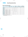
AC-DC Power Supplies Enclosed type
PLA
Power
Factor
Correction
World wide
Cost
Effective
Safety
Approvals
EMI
Inrush
current
limiting
OCP
OVP
PLA-series
Feature
EMI
Low Profile (100, 150, 300W : 1U size. 600W : 2U size)
Wide temperature range (-20C to +70C, Derating is required)
Harmonic attenuator (Complies with IEC61000-3-2 class A)
Universal input (AC85 - 264V, Derating is required)
Low power consumption at no load
Screw hold type terminal block (Only PLA300F and PLA600F)
Complies with SEMI F-47 (Option-U : Refer to instruction manual)
Various option
Complies with FCC-B, CISPR22-B, EN55011-B, EN55022-B,
VCCI-B
Safety agency approvals
UL60950-1, C-UL (CSA60950-1), EN60950-1, EN50178
UL508 (PLA100F-150F:24V, 36V, 48V) approved
Complies with DEN-AN
EMC Compliance : EN61204-3, EN61000-6-2
EN61000-4-2
EN61000-4-3
EN61000-4-4
EN61000-4-5
EN61000-4-6
EN61000-4-8
EN61000-4-11
5-year warranty (Refer to Instruction Manual)
CE marking
Low Voltage Directive
PLA-1
Ordering information
AC-DC Power Supplies Enclosed type
PLA100F
PLA
PL
1
A
100
2
3
F
4
Recommended EMI/EMC Filter
NAC-04-472
High voltage pulse noise type : NAP series
Low leakage current type : NAM series
*The EMI/EMC Filter is recommended
to connect with several devices.
-O
5
-O
6
1Series name
2Single output
3Output wattage
4Universal input
5Output voltage
6Optional *7
C : with Coating
R : Remote on/off
(Required external
power source)
J : Connector interface
T : Vertical terminal block
L : Lower power consumption
(0.5W max at AC240Vin,
no load, ErP-compliant)
Refer to instruction manual
5.1 about optional.
SPECIFICATIONS
* Please consider "PBA100F-5-N" about 5V output with case cover.
MODEL
VOLTAGE[V]
CURRENT[A]
ACIN 100V
ACIN 115V
ACIN 230V
FREQUENCY[Hz]
ACIN 100V
ACIN 115V
INPUT
ACIN 230V
ACIN 100V
POWER FACTOR
ACIN 115V
ACIN 230V
ACIN 100V
INRUSH CURRENT[A] ACIN 115V
ACIN 230V
LEAKAGE CURRENT[mA]
VOLTAGE[V]
ACIN 85-115V
CURRENT[A]
ACIN 115V-264V
ACIN 85-115V
WATTAGE[W]
ACIN 115V-264V
*4
LINE REGULATION[mV]
LOAD REGULATION Io=30 to 100%
*4 Io=0 to 30%
[mV]
0 to +40C
RIPPLE[mVp-p]
*1
-10 to 0C
Io: load factor Io=0 to 30%
OUTPUT
0 to +40C
RIPPLE NOISE[mVp-p]
*1
-10 to 0C
Io: load factor Io=0 to 30%
0 to +40C
TEMPERATURE REGULATION[mV]
-10 to +40C
*2
DRIFT[mV]
START-UP TIME[ms]
HOLD-UP TIME[ms]
OUTPUT VOLTAGE ADJUSTMENT RANGE[V]
OUTPUT VOLTAGE SETTING[V]
OVERCURRENT PROTECTION
PROTECTION OVERVOLTAGE PROTECTION[V]
CIRCUIT AND OPERATING INDICATION
OTHERS
REMOTE SENSING
REMOTE ON/OFF
*9
INPUT-OUTPUT・RC
INPUT-FG
ISOLATION
*9
OUTPUT・RC-FG
*9
OUTPUT-RC
OPERATING TEMP.,HUMID.AND ALTITUDE *5
STORAGE TEMP.,HUMID.AND ALTITUDE
ENVIRONMENT
VIBRATION
IMPACT
AGENCY APPROVALS
SAFETY AND
NOISE
CONDUCTED NOISE
REGULATIONS HARMONIC ATTENUATOR *8
EFFICIENCY[%]
PLA-2
PLA100F-12
PLA100F-15
PLA100F-24
PLA100F-36
PLA100F-48
AC85 - 264 1f (Output derating is required at AC85V - 115V. Refer to instruction manual 1.1 and 3.2) *3
(DC input *3)
1.2typ (Io=90%)
1.1typ (Io=100%)
0.6yp (Io=100%)
50 / 60 (47 - 63) (DC input and 440Hz *3)
82typ (Io=90%)
83typ (Io=90%)
85typ (Io=90%)
86typ (Io=90%)
86typ (Io=90%)
82typ (Io=100%)
83typ (Io=100%)
85typ (Io=100%)
86typ (Io=100%)
86typ (Io=100%)
85typ (Io=100%)
86typ (Io=100%)
88typ (Io=100%)
89typ (Io=100%)
89typ (Io=100%)
0.98typ (Io=90%)
0.98typ (Io=100%)
0.95typ (Io=100%) * Power factor correction is stopped at AC250V or more.
16typ (Io=90%) Ta=25C at cold start
16typ (Io=100%) Ta=25C at cold start
32typ (Io=100%) Ta=25C at cold start
0.75max (ACIN 115V / 240V, 60Hz, Io=100%, According to IEC60950-1 and DEN-AN)
12
15
24
36
48
Output derating is required at ACIN 115V or less (refer to instruction manual 3.2)
8.4
6.7
4.3
2.8
2.1
Output derating is required at ACIN 115V or less (refer to instruction manual 3.2)
100.8
100.5
103.2
100.8
100.8
48max
60max
96max
144max
192max
100max
120max
150max
150max
300max
Burst operation (Please contact us about detail)
120max
120max
120max
150max
150max
160max
160max
160max
200max
400max
500max
500max
500max
500max
500max
150max
150max
150max
200max
200max
180max
180max
180max
240max
500max
600max
600max
600max
600max
600max
120max
150max
240max
360max
480max
180max
180max
290max
440max
600max
48max
60max
96max
144max
192max
500typ (ACIN 115V, Io=100%) Ta=25C
20typ (ACIN 115V, Io=100%)
10.80 to 13.20
13.50 to 16.50
21.60 to 26.40
32.40 to 39.60
43.20 to 52.80
12.00 to 12.48
15.00 to 15.60
24.00 to 24.96
36.00 to 37.44
48.00 to 49.92
Works over 105% of rating and recovers automatically
13.80 to 16.80
17.25 to 21.00
27.60 to 33.60
41.40 to 50.40
54.00 to 67.20
LED (Green)
Not provided
Optional (Required external power source. Option -R)
AC3,000V 1minute, Cutoff current = 10mA, DC500V 50MW min (At room temperature)
AC2,000V 1minute, Cutoff current = 10mA, DC500V 50MW min (At room temperature)
AC500V 1minute, Cutoff current = 100mA, DC500V 50MW min (At room temperature)
AC500V 1minute, Cutoff current = 100mA, DC500V 50MW min (At room temperature)
-20 to +70C (Output derating is required), 20 - 90%RH (Non condensing), 3,000m (10,000 feet) max
-20 to +75C, 20 - 90%RH (Non condensing), 9,000m (30,000 feet) max
10 - 55Hz, 19.6m/s2 (2G), 3minutes period, 60minutes each along X, Y and Z axes
196.1m/s2 (20G), 11ms, once each X, Y and Z axes
UL60950-1, C-UL (CSA60950-1), EN60950-1, EN50178 UL508 (24Vout or more) Complies with DEN-AN
Complies with FCC-B, VCCI-B, CISPR22-B, EN55011-B, EN55022-B
Complies with IEC61000-3-2 class A
PLA100F
PLA
SPECIFICATIONS
CASE SIZE/WEIGHT
COOLING METHOD
WARRANTY WARRANTY
41X97X109mm [1.61X3.82X4.29 inches] (Excluding terminal block and screw) (WXHXD) / 500g max
Convection
5-year (Depends on the used condition)
OTHERS
*6
*1 This is the value that measured on measuring board with capacitor
of 22mF and 0.1mF at 150mm from output terminal.
Measured by 20MHz oscilloscope or Ripple-Noise meter
(Equivalent to KEISOKU-GIKEN: RM103).
Please refer to the instruction manual 1.6.
Ripple and ripple noise spec is change at Io=0 ∼ 30% by low
power mode.
*2 Drift is the change in DC output for an eight hour period after a
half-hour warm-up at 25C.
*3 Derating is required. As for DC input, please contact us.
*4 Please contact us about dynamic load and input response.
Also, please measure output voltage in average mode because of
burst operation at 30% load or less.
*5 Derating is required. Please refer to instruction manual 3.2.
*6 As for detail condtion, please refer to instruction manual 3.3.
*7 Please contact us about safety approvals for the model with option.
*8 Please contact us about other class.
*9 RC terminal is applied at option -R. And RC terminal is
isolated from input, output and FG.
* To meet the specifications, do not operate over-loaded
condition.
* Parallel operation is not possible.
* A sound may occur from power supply at peak loading.
Features
- Compact design (Depth: 109mm 4.29inches)
- High efficiency (88%typ PLA100F-24, AC230Vin, 100% load)
- Low power consumption (1.5W typ AC240Vin, no load at standard model)
- Lower power consumption (0.5Wmax AC240Vin, no load at option -L: refer to instruction manual)
- UL508 approved, and complies with SEMI F-47 (Depends on the used condition)
- Various option (Optional connectors : Vertical terminal block, Connector wiring)
Block diagram
FUSE
250V 3.15A
NOISE
FILTER
AC IN 85∼264V
INRUSH
CURRENT
LIMIT
RECTIFIER
FG
RC(㧙R)
CURRENT
SENSING
BOOSTER
INDUCTOR
CURRENT
SENSING
EXTERNAL
SOURCE
CONTROL
RECTIFIER
AND
FILTER
OVER VOLTAGE
PROTECTION
INVERTER
RECTIFIER
AND
FILTER
INVERTER
CONTROL
DC OUT
External view
External size of option R, J and T is different from standard model, and refer to "5 Option and others" of instruction manual for detail.
2-M3
Mounting hole
(Bottom sides)
Name plate
M3.5
AC(L)
Terminal cover
AC(N)
Point A
[0.86]
22±1.5
11.92±1.5 (LED)
[3.82]
97
51
2
1
CN4
Connector for
Remote ON/OFF (option)
[0.57]
14.6±1.5
14±1.5
[0.55]
32.8±1.5
[1.29]
Output terminal(+)
Output voltage
adjustable potentiometer
LED
[2.01]
9.5
[0.37]
6.2
[0.24]
8.2
Output terminal(-)
[0.32]
FG( )
19.5
[0.77]
12.5max
76±0.5
[2.99]
109
[0.49]
[4.29]
[0.47]
101
[0.16]
[3.98]
33.5
66.5±0.5
[1.32]
[2.62]
41
[1.61]
[0.71]
[0.47]
12 18±0.5
[0.83]
3.5
21 [0.14]
21
[0.83]
28.5
[1.12]
3.5
[0.46]
¶ Tolerance : ±1 [±0.04]
¶ Weight : 500g max
¶ PCB Material/thickness : CEM-3 / 1.6mm [0.06inches]
¶ Chassis material : Aluminum
¶ Cover material : Electric galvanizing steel board
¶ Dimensions in mm, [ ]=inches
¶ Mounting torque : 0.49N-m max
¶ Screw tightening torque : M3.5 1.0N-m max
¶ Please connect safety ground to FG terminal on the unit.
4
[0.14]
11.6±1.5 (potentiometer)
3-M3
Mounting hole
PLA-3
Ordering information
AC-DC Power Supplies Enclosed type
PLA150F
PLA
PL
1
A
150
2
3
F
4
Recommended EMI/EMC Filter
NAC-04-472
High voltage pulse noise type : NAP series
Low leakage current type : NAM series
*The EMI/EMC Filter is recommended
to connect with several devices.
-O
5
-O
6
1Series name
2Single output
3Output wattage
4Universal input
5Output voltage
6Optional *7
C : with Coating
R : Remote on/off
(Required external
power source)
J : Connector interface
T : Vertical terminal block
L : Lower power consumption
(0.5W max at AC240Vin,
no load, ErP-compliant)
Refer to instruction manual
5.1 about optional.
SPECIFICATIONS
* Please consider "PBA150F-5-N" about 5V output with case cover.
MODEL
VOLTAGE[V]
CURRENT[A]
ACIN 100V
ACIN 115V
ACIN 230V
FREQUENCY[Hz]
ACIN 100V
ACIN 115V
INPUT
ACIN 230V
ACIN 100V
POWER FACTOR
ACIN 115V
ACIN 230V
ACIN 100V
INRUSH CURRENT[A] ACIN 115V
ACIN 230V
LEAKAGE CURRENT[mA]
VOLTAGE[V]
ACIN 85-115V
CURRENT[A]
ACIN 115V-264V
ACIN 85-115V
WATTAGE[W]
ACIN 115V-264V
*4
LINE REGULATION[mV]
LOAD REGULATION Io=30 to 100%
*4 Io=0 to 30%
[mV]
0 to +40C
RIPPLE[mVp-p]
*1
-10 to 0C
Io: load factor Io=0 to 30%
OUTPUT
0 to +40C
RIPPLE NOISE[mVp-p]
*1
-10 to 0C
Io: load factor Io=0 to 30%
0 to +40C
TEMPERATURE REGULATION[mV]
-10 to +40C
*2
DRIFT[mV]
START-UP TIME[ms]
HOLD-UP TIME[ms]
OUTPUT VOLTAGE ADJUSTMENT RANGE[V]
OUTPUT VOLTAGE SETTING[V]
OVERCURRENT PROTECTION
PROTECTION OVERVOLTAGE PROTECTION[V]
CIRCUIT AND OPERATING INDICATION
OTHERS
REMOTE SENSING
REMOTE ON/OFF
*9
INPUT-OUTPUT・RC
INPUT-FG
ISOLATION
*9
OUTPUT・RC-FG
*9
OUTPUT-RC
OPERATING TEMP.,HUMID.AND ALTITUDE *5
STORAGE TEMP.,HUMID.AND ALTITUDE
ENVIRONMENT
VIBRATION
IMPACT
AGENCY APPROVALS
SAFETY AND
CONDUCTED NOISE
NOISE
REGULATIONS HARMONIC ATTENUATOR *8
EFFICIENCY[%]
PLA-4
PLA150F-12
PLA150F-15
PLA150F-24
PLA150F-36
PLA150F-48
AC85 - 264 1f (Output derating is required at AC85V - 115V. Refer to instruction manual 1.1 and 3.2) *3
(DC input *3)
1.7typ (Io=90%)
1.6typ (Io=100%)
0.8yp (Io=100%)
50 / 60 (47 - 63) (DC input and 440Hz *3)
84typ (Io=90%)
84typ (Io=90%)
87typ (Io=90%)
87typ (Io=90%)
87typ (Io=90%)
84typ (Io=100%)
84typ (Io=100%)
87typ (Io=100%)
87typ (Io=100%)
87typ (Io=100%)
87typ (Io=100%)
87typ (Io=100%)
90typ (Io=100%)
90typ (Io=100%)
90typ (Io=100%)
0.98typ (Io=90%)
0.98typ (Io=100%)
0.95typ (Io=100%) * Power factor correction is stopped at AC250V or more.
16typ (Io=90%) Ta=25C at cold start
16typ (Io=100%) Ta=25C at cold start
32typ (Io=100%) Ta=25C at cold start
0.75max (ACIN 115V / 240V, 60Hz, Io=100%, According to IEC60950-1 and DEN-AN)
12
15
24
36
48
Output derating is required at ACIN 115V or less (refer to instruction manual 3.2)
12.5
10
6.4
4.2
3.2
Output derating is required at ACIN 115V or less (refer to instruction manual 3.2)
150.0
150.0
153.6
151.2
153.6
48max
60max
96max
144max
192max
100max
120max
150max
150max
300max
Burst operation (Please contact us about detail)
120max
120max
120max
150max
150max
160max
160max
160max
200max
400max
500max
500max
500max
500max
500max
150max
150max
150max
200max
200max
180max
180max
180max
240max
500max
600max
600max
600max
600max
600max
120max
150max
240max
360max
480max
180max
180max
290max
440max
600max
48max
60max
96max
144max
192max
500typ (ACIN 115V, Io=100%) Ta=25C
20typ (ACIN 115V, Io=100%)
10.80 to 13.20
13.50 to 16.50
21.60 to 26.40
32.40 to 39.60
43.20 to 52.80
12.00 to 12.48
15.00 to 15.60
24.00 to 24.96
36.00 to 37.44
48.00 to 49.92
Works over 105% of rating and recovers automatically
13.80 to 16.80
17.25 to 21.00
27.60 to 33.60
41.40 to 50.40
54.00 to 67.20
LED (Green)
Not provided
Optional (Required external power source. Option -R)
AC3,000V 1minute, Cutoff current = 10mA, DC500V 50MW min (At room temperature)
AC2,000V 1minute, Cutoff current = 10mA, DC500V 50MW min (At room temperature)
AC500V 1minute, Cutoff current = 100mA, DC500V 50MW min (At room temperature)
AC500V 1minute, Cutoff current = 100mA, DC500V 50MW min (At room temperature)
-20 to +70C (Output derating is required), 20 - 90%RH (Non condensing), 3,000m (10,000 feet) max
-20 to +75C, 20 - 90%RH (Non condensing), 9,000m (30,000 feet) max
10 - 55Hz, 19.6m/s2 (2G), 3minutes period, 60minutes each along X, Y and Z axes
196.1m/s2 (20G), 11ms, once each X, Y and Z axes
UL60950-1, C-UL (CSA60950-1), EN60950-1, EN50178 UL508 (24Vout or more) Complies with DEN-AN
Complies with FCC-B, VCCI-B, CISPR22-B, EN55011-B, EN55022-B
Complies with IEC61000-3-2 class A
PLA150F
PLA
SPECIFICATIONS
CASE SIZE/WEIGHT
COOLING METHOD
WARRANTY WARRANTY
41X97X129mm [1.61X3.82X5.08 inches] (Excluding terminal block and screw) (WXHXD) / 600g max
Convection
5-year (Depends on the used condition)
OTHERS
*6
*1 This is the value that measured on measuring board with capacitor
of 22mF and 0.1mF at 150mm from output terminal.
Measured by 20MHz oscilloscope or Ripple-Noise meter
(Equivalent to KEISOKU-GIKEN: RM103).
Please refer to the instruction manual 1.6.
Ripple and ripple noise spec is change at Io=0 ∼ 30% by low
power mode.
*2 Drift is the change in DC output for an eight hour period after a
half-hour warm-up at 25C.
*3 Derating is required. As for DC input, please contact us.
*4 Please contact us about dynamic load and input response.
Also, please measure output voltage in average mode because of
burst operation at 30% load or less.
*5 Derating is required. Please refer to instruction manual 3.2.
*6 As for detail condtion, please refer to instruction manual 3.3.
*7 Please contact us about safety approvals for the model with option.
*8 Please contact us about other class.
*9 RC terminal is applied at option -R. And RC terminal is
isolated from input, output and FG.
* To meet the specifications, do not operate over-loaded
condition.
* Parallel operation is not possible.
* A sound may occur from power supply at peak loading.
Features
- Compact design (Depth: 129mm 5.08inches)
- High efficiency (90%typ PLA150F-24, AC230Vin, 100% load)
- Low power consumption (1.5W typ AC240Vin, no load at standard model)
- Lower power consumption (0.5Wmax AC240Vin, no load at option -L: refer to instruction manual)
- UL508 approved, and complies with SEMI F-47 (Depends on the used condition)
- Various option (Optional connectors : Vertical terminal block, Connector wiring)
Block diagram
FUSE
250V 4A
NOISE
FILTER
AC IN 85∼264V
INRUSH
CURRENT
LIMIT
RECTIFIER
FG
RC(㧙R)
CURRENT
SENSING
BOOSTER
INDUCTOR
CURRENT
SENSING
EXTERNAL
SOURCE
CONTROL
RECTIFIER
AND
FILTER
OVER VOLTAGE
PROTECTION
INVERTER
RECTIFIER
AND
FILTER
INVERTER
CONTROL
DC OUT
External view
External size of option R, J and T is different from standard model, and refer to "5 Option and others" of instruction manual for detail.
Name plate
2-M3
Mounting hole
(Bottom sides)
Point B
M3.5
AC(L)
Terminal cover
AC(N)
Point A
97
[3.82]
9.5
[0.37]
[0.24]
Output terminal(+)
6.2
8.2
Output terminal(-)
[0.32]
FG( )
49.5
[1.95]
2
1
CN4
Connector for
Remote ON/OFF (option)
12.5max
129
[0.49]
[5.08]
4
121
[0.16]
[4.76]
48
[1.89]
70±0.5
[2.76]
41
[1.61]
[0.47] [0.71]
12 18±0.5
3.5
[0.83]
28.5
[1.12]
21
3.5
[0.46]
[0.83]
[0.47]
11.6±1.5(potentiometer)
¶ Tolerance : ±1 [±0.04]
¶ Weight : 600g max
¶ PCB Material/thickness : CEM-3 / 1.6mm [0.06inches]
¶ Chassis material : Aluminum
¶ Cover material : Electric galvanizing steel board
¶ Dimensions in mm, [ ]=inches
¶ Mounting torque : 0.49N-m max
¶ Screw tightening torque : M3.5 1.0N-m max
¶ Please connect safety ground to FG terminal on the unit.
96±0.5
[3.78]
21 [0.14]
11.92±1.5(LED)
19
[0.75]
[0.14]
[0.86]
22±1.5
[0.57]
14.6±1.5
14±1.5
[0.55]
B
LED
32.8±1.5
[1.29]
Output voltage
adjustable potentiometer
3-M3
Mounting hole
PLA-5
Ordering information
AC-DC Power Supplies Enclosed type
PLA300F
PLA
PL
1
A
2
300
3
F
4
Recommended EMI/EMC Filter
NAC-06-472
High voltage pulse noise type : NAP series
Low leakage current type : NAM series
*The EMI/EMC Filter is recommended
to connect with several devices.
-O
5
-O
6
1Series name
2Single output
3Output wattage
4Universal input
5Output voltage
6Optional *7
C : with Coating
G : Low leakage current
V : External potentiometer for
output voltage adjustment
U : Low input voltage stop
(Complies with SEMI F-47)
R : Remote on/off
(Required external power source)
F4: Low speed fan
T2: Horizontal terminal block
(Not screw hold type)
Refer to instruction manual
5.1 about optional.
SPECIFICATIONS
MODEL
VOLTAGE[V]
CURRENT[A]
ACIN 100V
ACIN 115V
ACIN 230V
FREQUENCY[Hz]
ACIN 100V
ACIN 115V
INPUT
ACIN 230V
ACIN 100V
POWER FACTOR
ACIN 115V
ACIN 230V
ACIN 100V
INRUSH CURRENT[A] ACIN 115V
ACIN 230V
LEAKAGE CURRENT[mA]
VOLTAGE[V]
ACIN 85-115V
CURRENT[A]
ACIN 115V-264V
ACIN 85-115V
WATTAGE[W]
ACIN 115V-264V
*4
LINE REGULATION[mV]
LOAD REGULATION[mV] *4
0 to +50C
RIPPLE[mVp-p]
*1
-10 to 0C
OUTPUT
0 to +50C
RIPPLE NOISE[mVp-p]
*1
-10 to 0C
0 to +50C
TEMPERATURE REGULATION[mV]
-10 to +50C
*2
DRIFT[mV]
START-UP TIME[ms]
HOLD-UP TIME[ms]
OUTPUT VOLTAGE ADJUSTMENT RANGE[V]
OUTPUT VOLTAGE SETTING[V]
OVERCURRENT PROTECTION
PROTECTION OVERVOLTAGE PROTECTION[V]
CIRCUIT AND OPERATING INDICATION
OTHERS
REMOTE SENSING
REMOTE ON/OFF
*10
INPUT-OUTPUT-RC
INPUT-FG
ISOLATION
*10
OUTPUT-RC-FG
*10
OUTPUT-RC
OPERATING TEMP.,HUMID.AND ALTITUDE *5
STORAGE TEMP.,HUMID.AND ALTITUDE
ENVIRONMENT
VIBRATION
IMPACT
AGENCY APPROVALS
SAFETY AND
CONDUCTED NOISE
NOISE
REGULATIONS HARMONIC ATTENUATOR *9
EFFICIENCY[%]
PLA-6
PLA300F-5
PLA300F-12
PLA300F-15
PLA300F-24
PLA300F-36
PLA300F-48
AC85 - 264 1f (Output derating is required at AC85V - 115V. Refer to instruction manual 1.1 and 3.2) *3
(DC input and AC265 - 277V input *3)
3.1typ (Io=90%) 3.4typ (Io=90%)
3.0typ (Io=100%) 3.3typ (Io=100%)
1.5typ (Io=100%) 1.7typ (Io=100%)
50 / 60 (47 - 63) (DC input and 440Hz *3)
73typ (Io=90%) 78typ (Io=90%) 80typ (Io=90%) 84typ (Io=90%) 84typ (Io=90%) 84typ (Io=90%)
74typ (Io=100%) 78typ (Io=100%) 80typ (Io=100%) 84typ (Io=100%) 84typ (Io=100%) 84typ (Io=100%)
77typ (Io=100%) 81typ (Io=100%) 83typ (Io=100%) 87typ (Io=100%) 87typ (Io=100%) 87typ (Io=100%)
0.98typ (Io=90%)
0.98typ (Io=100%)
0.95typ (Io=100%)
20typ (Io=90%) Ta=25C at cold start
20typ (Io=100%) Ta=25C at cold start
40typ (Io=100%) Ta=25C at cold start
0.75max (ACIN 115V / 240V, 60Hz, Io=100%, According to IEC60950-1 and DEN-AN)
5
12
15
24
36
48
Output derating is required at ACIN 115V or less (refer to instruction manual 3.2)
50
25
20
12.5
8.4
6.3
Output derating is required at ACIN 115V or less (refer to instruction manual 3.2)
250
300
300
300
302.4
302.4
20max
48max
60max
96max
144max
192max
40max
100max
120max
150max
150max
300max
80max
120max
120max
120max
150max
150max
140max
160max
160max
160max
160max
400max
120max
150max
150max
150max
200max
200max
160max
180max
180max
180max
240max
500max
50max
120max
150max
240max
360max
480max
75max
180max
180max
290max
440max
600max
20max
48max
60max
96max
144max
192max
300typ (ACIN 115V, Io=100%)
20typ (ACIN 115V, Io=100%)
4.50 to 5.50
10.80 to 13.20
13.50 to 16.50
21.60 to 26.40
32.40 to 39.60
43.20 to 52.80
5.00 to 5.15
12.00 to 12.48
15.00 to 15.60
24.00 to 24.96
36.00 to 37.44
48.00 to 49.92
Works over 105% of rating and recovers automatically
5.75 to 7.00
13.80 to 16.80
17.25 to 21.00
27.60 to 33.60
41.40 to 50.40
55.20 to 67.20
LED (Green)
Not provided
Optional (Required external power source. Option -R)
AC3,000V 1minute, Cutoff current = 10mA, DC500V 50MW min (At room temperature)
AC2,000V 1minute, Cutoff current = 10mA, DC500V 50MW min (At room temperature)
AC500V 1minute, Cutoff current = 100mA, DC500V 50MW min (At room temperature)
AC500V 1minute, Cutoff current = 100mA, DC500V 50MW min (At room temperature)
-20 to +70C (Output derating is required), 20 - 90%RH (Non condensing), 3,000m (10,000 feet) max
-20 to +75C, 20 - 90%RH (Non condensing), 9,000m (30,000 feet) max
10 - 55Hz, 19.6m/s2 (2G), 3minutes period, 60minutes each along X, Y and Z axes
196.1m/s2 (20G), 11ms, once each X, Y and Z axes
UL60950-1, C-UL (CSA60950-1), EN60950-1, EN50178 Complies with DEN-AN
Complies with FCC-B, VCCI-B, CISPR22-B, EN55011-B, EN55022-B
Complies with IEC61000-3-2 class A
PLA300F
PLA
SPECIFICATIONS
CASE SIZE/WEIGHT
COOLING METHOD
WARRANTY WARRANTY
OTHERS
102X41X190mm [4.02X1.61X7.48 inches] (Excluding terminal block and screw) (WXHXD) / 1.0kg max
Forced cooling (internal fan)
5-year (Depends on the used condition)
*8
*6
*1 This is the value that measured on measuring board with capacitor
of 22mF and 0.1mF at 150mm from output terminal.
Measured by 20MHz oscilloscope or Ripple-Noise meter
(Equivalent to KEISOKU-GIKEN: RM103).
Please refer to the instruction manual 1.6.
*2 Drift is the change in DC output for an eight hour period after a
half-hour warm-up at 25C.
*3 Derating is required. As for DC input, 440Hz input and AC265 to
277V input, please contact us.
*4 Please contact us about dynamic load and input response.
*5 Derating is required. Please refer to instruction manual 3.2.
*6 As for detail condtion, please refer to instruction manual 3.3.
*7 Please contact us about safety approvals for the model with option.
*8 Fan speed is changed by load factor.
*9 Please contact us about other class.
*10 RC terminal is applied at option -R. And RC terminal is
isolated from input, output and FG.
* To meet the specifications, do not operate over-loaded
condition.
* Parallel operation is not possible.
* A sound may occur from power supply at peak loading.
Features
- Economical model
- Long lifetime (Refer to instruction manual)
- Low profile (41mm, 1.61 inch = meet to 1U height)
- Wide temperature range (-20 to +70 Refer to instruction manual)
- Screw hold type terminal block
- Fan speed control (At no load condition)
- Various option
- Complies with SEMI F-47 (Option-U: Refer to instruction manual)
Block diagram
FUSE
250V 10A
NOISE
FILTER
AC IN 85 - 264V
INRUSH
CURRENT
LIMIT
RECTIFIER
FG
CURRENT
SENSING
BOOSTER
INDUCTOR
RECTIFIER
AND
FILTER
CURRENT
SENSING
CONTROL
CONTROL
OVER VOLTAGE
PROTECTION
INVERTER
INVERTER
RECTIFIER
AND
FILTER
THERMAL
PROTECTION
THREE
TERMINAL
REGULATOR
CONTROL
DC OUT
FAN
External view
External size of option V, option R and option T2 is different from standard model, and refer to ”5. Option and Others” of instruction manual for detail.
±1.5
16.6
[0.65]
13.5
±1.5
(LED)
[0.53]
102
[0.2max]
150 ±0.5
[0.77]
[5.91]
AIR FLOW
[1.61]
[0.98]
5max
[7.48]
25 ±0.5
190
19.5
[4.02]
[2.36]
60 ±0.5
[5.91]
[0.77]
19.5
150 ±0.5
[0.49]
10.5
¶ Tolerance : ±1 [±0.04]
¶ Weight : 1.0kg max
¶ PCB Material/thickness : CEM-3 / 1.6mm [0.06inches]
¶ Chassis material : Aluminum
¶ Case material : Electric galvanizing steel board
¶ Dimensions in mm, [ ]=inches
¶ Mounting torque : 1.2N-m max
¶ Screw tightening torque : 1.6N-m max
¶ Please connect safety ground to FG terminal on the unit.
12.5
[0.41]
5.7
[0.22]
10
M4
4-M4
Mounting Hole
(Bottom sides)
41
[0.78]
Name plate
[0.79max]
[0.39]
19.8 ±1.5
5.75 ±1.5
20max
AC AC
-V FG (N) (L)
FG( )
AC(N)
AC(L)
+V +V -V
Output terminal (-)
V.ADJ
Output terminal (+)
[0.23]
Output voltage
adjustable potentiometer
(potentiometer)
8.6
LED
±1.5
[0.34]
13.3
[0.52]
4-M4
Mounting Hole
PLA-7
Ordering information
AC-DC Power Supplies Enclosed type
PLA600F
PLA
PL
1
A
2
600
3
F
4
Recommended EMI/EMC Filter
NAC-16-472
High voltage pulse noise type : NAP series
Low leakage current type : NAM series
*The EMI/EMC Filter is recommended
to connect with several devices.
-O
5
-O
6
1Series name
2Single output
3Output wattage
4Universal input
5Output voltage
6Optional *7
C : with Coating
G : Low leakage current
V : External potentiometer for
output voltage adjustment
U : Low input voltage stop
(Complies with SEMI F-47)
W: Parallel operation,
LV alarm Remote sensing
R : Remote on/off
(Required external power source)
F4: Low speed fan
T2: Horizontal terminal block
(Not screw hold type)
Refer to instruction manual
5.1 about optional.
SPECIFICATIONS
MODEL
VOLTAGE[V]
CURRENT[A]
ACIN 100V
ACIN 115V
ACIN 230V
FREQUENCY[Hz]
ACIN 100V
ACIN 115V
INPUT
ACIN 230V
ACIN 100V
POWER FACTOR
ACIN 115V
ACIN 230V
ACIN 100V
INRUSH CURRENT[A] ACIN 115V
ACIN 230V
LEAKAGE CURRENT[mA]
VOLTAGE[V]
ACIN 85-115V
CURRENT[A]
ACIN 115V-264V
ACIN 85-115V
WATTAGE[W]
ACIN 115V-264V
*8
LINE REGULATION[mV]
LOAD REGULATION[mV] *8
0 to +50C
RIPPLE[mVp-p]
*1
-20 to 0C
OUTPUT
0 to +50C
RIPPLE NOISE[mVp-p]
*1
-20 to 0C
0 to +50C
TEMPERATURE REGULATION[mV]
-20 to +50C
*2
DRIFT[mV]
START-UP TIME[ms]
HOLD-UP TIME[ms]
OUTPUT VOLTAGE ADJUSTMENT RANGE[V]
OUTPUT VOLTAGE SETTING[V]
OVERCURRENT PROTECTION
PROTECTION OVERVOLTAGE PROTECTION[V]
CIRCUIT AND OPERATING INDICATION
OTHERS
REMOTE SENSING
REMOTE ON/OFF
*3
INPUT-OUTPUT-RC
INPUT-FG
ISOLATION
*3
OUTPUT-RC-FG
*3
OUTPUT-RC
OPERATING TEMP.,HUMID.AND ALTITUDE *5
STORAGE TEMP.,HUMID.AND ALTITUDE
ENVIRONMENT
VIBRATION
IMPACT
AGENCY APPROVALS
SAFETY AND
CONDUCTED NOISE
NOISE
REGULATIONS HARMONIC ATTENUATOR *10
EFFICIENCY[%]
PLA-8
PLA600F-5
PLA600F-12
PLA600F-15
PLA600F-24
PLA600F-36
PLA600F-48
AC85 - 264 1f (Output derating is required at AC85V - 115V. Refer to instruction manual 1.1 and 3.2) *4
(DC input and AC265 - 277V input *4)
6.2typ (Io=90%) 6.7typ (Io=90%)
6.0typ (Io=100%) 6.5typ (Io=100%)
3.0typ (Io=100%) 3.2typ (Io=100%)
50 / 60 (47 - 63) (DC input and 440Hz *4)
74typ (Io=90%) 81typ (Io=90%) 81typ (Io=90%) 84typ (Io=90%) 85typ (Io=90%) 85typ (Io=90%)
75typ (Io=100%) 81typ (Io=100%) 81typ (Io=100%) 84typ (Io=100%) 85typ (Io=100%) 85typ (Io=100%)
77typ (Io=100%) 84typ (Io=100%) 84typ (Io=100%) 88typ (Io=100%) 88typ (Io=100%) 88typ (Io=100%)
0.98typ (Io=90%)
0.98typ (Io=100%)
0.95typ (Io=100%)
20/40typ (Io=90%) (Primary inrush current /Secondary inrush current) (More than 3sec to re-start)
20/40typ (Io=100%) (Primary inrush current /Secondary inrush current) (More than 3sec to re-start)
40/40typ (Io=100%) (Primary inrush current /Secondary inrush current) (More than 3sec to re-start)
1.5max (ACIN 115V / 240V, 60Hz, Io=100%, According to IEC60950-1 and DEN-AN)
5
12
15
24
36
48
Output derating is required at ACIN 115V or less (refer to instruction manual 3.2)
100
50
40
25
16.7
12.5
Output derating is required at ACIN 115V or less (refer to instruction manual 3.2)
500
600
600
600
601.2
600
20max
48max
60max
96max
144max
192max
40max
100max
120max
150max
150max
300max
80max
120max
120max
120max
150max
150max
140max
160max
160max
160max
160max
400max
120max
150max
150max
150max
200max
200max
160max
180max
180max
180max
240max
500max
50max
120max
150max
240max
360max
480max
75max
180max
180max
290max
440max
600max
20max
48max
60max
96max
144max
192max
300typ (ACIN 115V, Io=100%)
20typ (ACIN 115V, Io=100%)
4.50 to 5.50
10.80 to 13.20
13.50 to 16.50
21.60 to 26.40
32.40 to 39.60
43.20 to 52.80
5.00 to 5.15
12.00 to 12.48
15.00 to 15.60
24.00 to 24.96
36.00 to 37.44
48.00 to 49.92
Works over 105% of rating and recovers automatically
5.75 to 7.00
13.80 to 16.80
17.25 to 21.00
27.60 to 33.60
41.40 to 50.40
55.20 to 67.20
LED (Green)
Optional (Option -W)
Optional (Required external power source. Option -R)
AC3,000V 1minute, Cutoff current = 10mA, DC500V 50MW min (At room temperature)
AC2,000V 1minute, Cutoff current = 10mA, DC500V 50MW min (At room temperature)
AC500V 1minute, Cutoff current = 100mA, DC500V 50MW min (At room temperature)
AC500V 1minute, Cutoff current = 100mA, DC500V 50MW min (At room temperature)
-20 to +70C (Output derating is required), 20 - 90%RH (Non condensing), 3,000m (10,000 feet) max
-20 to +75C, 20 - 90%RH (Non condensing), 9,000m (30,000 feet) max
10 - 55Hz, 19.6m/s2 (2G), 3minutes period, 60minutes each along X, Y and Z axes
196.1m/s2 (20G), 11ms, once each X, Y and Z axes
UL60950-1, C-UL (CSA60950-1), EN60950-1, EN50178 Complies with DEN-AN
Complies with FCC-B, VCCI-B, CISPR22-B, EN55011-B, EN55022-B
Complies with IEC61000-3-2 class A
PLA600F
PLA
SPECIFICATIONS
CASE SIZE/WEIGHT
COOLING METHOD
WARRANTY WARRANTY
OTHERS
120X61X215mm [4.72X2.40X8.46 inches] (Excluding terminal block and screw) (WXHXD) / 2.0kg max
Forced cooling (internal fan)
5-year (Depends on the used condition)
*9
*6
*1 This is the value that measured on measuring board with capacitor
of 22mF and 0.1mF at 150mm from output terminal.
Measured by 20MHz oscilloscope or Ripple-Noise meter
(Equivalent to KEISOKU-GIKEN: RM103).
Please refer to the instruction manual 1.6.
*2 Drift is the change in DC output for an eight hour period after a
half-hour warm-up at 25C.
*3 RC terminal is applied at option -R. And RC terminal is isolated
from input, output and FG.
*4 Derating is required. As for DC input, 440Hz input and AC265 to
277V input, please contact us.
*5 Derating is required. Please refer to instruction manual 3.2.
*6 As for detail condtion, please refer to instruction manual 3.3.
*7 Please contact us about safety approvals for the model with option.
*8 Please contact us about dynamic load and input response.
*9 Fan speed is changed by load factor.
*10 Please contact us about other class.
* To meet the specifications, do not operate over-loaded condition.
* Parallel operation with other model is not possible. In case of
parallel operation with same model, please use option -W.
* A sound may occur from power supply at peak loading.
Features
- Economical model
- Screw hold type terminal block (Only input and FG terminal)
- Long lifetime (Refer to instruction manual)
- Low profile (61mm, 2.40 inch = meet to 2U height)
- Fan speed control (At no load condition)
- Various option
- Wide temperature range (-20
instruction manual)
- Complies with SEMI F-47 (Option-U: Refer to instruction manual)
to +70
Refer to
Block diagram
FUSE
250V 16A
AC IN 85 - 264V
BOOSTER
INDUCTOR
NOISE
FILTER
RECTIFIER
INRUSH
CURRENT
LIMIT
CURRENT
SENSING
RECTIFIER
AND
FILTER
INVERTER
FG
CONTROL
CURRENT
SENSING
RC (-R)
External source
THERMAL
PROTECTION
CONTROL
CONTROL
PARALLEL-OPERATION
CIRCUIT
Current balance (-W)
OVER VOLTAGE
PROTECTION
DETECTING
OUTPUT VOLTAGE
LV alarm (-W)
RECTIFIER
AND
FILTER
INVERTER
DC OUT
THREE
TERMINAL
REGULATOR
FAN
External view
External size of option V, option W, option R and option T2 are different from standard model, and refer to ”5. Option and
Others” of instruction manual for detail.
26.6 ±1.5
[1.05]
16.6 ±1.5
[0.65]
12.5
±1.5
(LED)
[0.49]
12.3 ±1.5 (potentiometer)
150 ±0.5
[5.91]
61
[2.4]
AIR FLOW
38
35
[1.38]
120
[0.12max]
±0.5
3max
[8.46]
[4.72]
±0.5
100
[3.94]
10
[0.39]
150 ±0.5
[5.91]
215
[1.5]
¶ Tolerance : ±1 [±0.04]
¶ Weight : 2.0kg max
¶ PCB Material/thickness : CEM-3 / 1.6mm [0.06inches]
¶ Chassis material : Electric galvanizing steel board
¶ Case material : Electric galvanizing steel board
¶ Dimensions in mm, [ ]=inches
¶ Mounting torque : 1.5N-m max
¶ Screw tightening torque : M3.5 0.8N-m max
M4 1.6N-m max
¶ Please connect safety ground to FG terminal on the unit.
35
[1.38]
[0.61]
M3.5
(AC,FG)
4-M4
Mounting Hole
(Bottom sides)
Name plate
15.5
[0.61]
[3.12]
10
[0.39]
AC AC
FG (N) (L)
8.1
-V
[0.32]
-V
15.5 ±1.5
79.25 ±1.5
+V
FG( )
AC(N)
AC(L)
10
7.4
[0.29]
12
+V
Output terminal (-)
21max
[0.83max]
[0.39]
±1.5
Output
terminal cover
[0.47]
[0.73]
[0.98]
24.8
V.ADJ
Output terminal (+)
[0.41]
LED
Output voltage
adjustable potentiometer
10.5 ±1.5
M4
(+V,-V)
18.5 ±1.5
[0.48]
4-M4
Mounting Hole
PLA-9
Basic Characteristics Data
PLA
Basic Characteristics Data
Model
PLA100F
PLA150F
PLA300F
PLA600F
Circuit method
Switching
frequency
[kHz]
Active filter
40 to 160
Flyback converter 20 to 150 *2
Active filter
40 to 160
Flyback converter 20 to 150 *2
Active filter
60
Forward converter
140
Active filter
60
Forward converter
220
Input
current
[A] *1
1.2
Rated
input fuse
250V 3.15A Thermistor
Series/Parallel
operation availability
PCB/Pattern
Material
Single Double
sided
sided
Series
operation
Parallel
operation
CEM-3
Yes
Yes
No
1.7
250V 4A
Thermistor
CEM-3
Yes
Yes
No
3.4
250V 10A
Thermistor
CEM-3
Yes
Yes
No
6.7
250V 16A
SCR
CEM-3
Yes
*3
*1 The value of input current is at ACIN 100V and 90% load.
*2 Burst mode frequency is changed by the used condition. Please contact us about detail.
*3 Available by option -W. Please refer to instruction manual "5. Option and Others".
PLA-10
Inrush
current
protection
circuit
Yes
AC-DC Power Supplies Enclosed type Instruction Manual
PLA
1
2
3
Function
PLA-12
1.1
Input Voltage Range
PLA-12
1.2
Inrush Current Limiting
PLA-12
1.3
Overcurrent Protection
PLA-12
1.4
Overvoltage Protection
PLA-12
1.5
Thermal Protection
PLA-12
1.6
Output Ripple and Ripple Noise
PLA-13
1.7
Output Voltage Adjustment
PLA-13
1.8
Isolation
PLA-13
1.9
Low Power Consumption
PLA-13
1.10
Remote ON/OFF
PLA-13
1.11
Remote Sensing
PLA-13
1.12
LV Alarm
PLA-13
Series Operation and Parallel Operation
PLA-13
2.1
Series Operation
PLA-13
2.2
Parallel Operation
PLA-14
Assembling and Installation Method
PLA-14
3.1
Installation Method
PLA-14
3.2
Derating
PLA-14
3.3
Expected Life and Warranty
PLA-15
4
Ground
PLA-16
5
Option and Others
PLA-16
5.1
Outline of Options
PLA-16
5.2
Others
PLA-20
PLA-11
AC-DC Power Supplies Enclosed type
Instruction Manual
PLA
¡When the switch of the input is turned on, the primary inrush current and secondary inrush current will be generated because the
1 Function
thyristor technique is used for the inrush current limiting circuit.
1.3 Overcurrent Protection
1.1 Input Voltage Range
¡Input voltage range of the power supplies is from AC85V to
AC264V (please see SPECIFICATIONS for details).
¡An overcurrent protection circuit is built-in and activated at 105%
of the rated current. A unit automatically recovers when a fault
condition is removed.
¡To comply with safety standards, input voltage range is AC100AC240V(50/60Hz).
Please do not use a unit in short circuit and/or under an overcur-
¡If input value doesn’t fall within above range, a unit may not operate in accordance with specifications and/or start hunting or fail.
¡Intermittent Operation Mode
When the overcurrent protection circuit is activated and the output
If you need to apply a square waveform input voltage, which is
voltage drops to a certain extent, the output becomes intermittent
commonly used in UPS and inverters, please contact us.
so that the average current will also decrease.
¡When the input voltage changes suddenly, the output voltage
might exceed the specification. Please contact us.
¡When DC input voltage is applied, external DC fuse is required for
the protection. Please contact us about detail.
¿ PLA100F, PLA150F
rent condition.
1.4 Overvoltage Protection
¡An overvoltage protection circuit is built-in. If the overvoltage protection circuit is activated, shut down the input voltage, wait more
than 3 minutes and turn on the AC input again to recover the out-
¡Power factor correction circuit will be stopped at AC250Vin
or more. The operation is normal except decreasing the power
put voltage. Recovery time varies depending on such factors as
input voltage value at the time of the operation.
Remarks :
factor. Please contact us about detail.
¡Operation stop voltage is set at a lower value by output power derating.
Please avoid applying a voltage exceeding the rated voltage to an
-Use Conditions
tion or fail. If you cannot avoid doing so, for example, if you need
Maximum output power
PLA100F
PLA150F
40W
60W
Input AC50V (DC70V)
Duty 1s/30s
*Please avoid using continuously for more than 1 second
under above conditions. Doing so may cause a failure.
¿ PLA300F, PLA600F
¡By using -U option, it is possible to operate at input voltage dip
condition that is lower than AC85V. Output derating is required
(Refer to 5. Option and Others). Please contact us for details.
1.2 Inrush Current Limiting
¡An inrush current limiting circuit is built-in.
¡If you need to use a switch on the input side, please select one
that can withstand an input inrush current.
output terminal. Doing so may cause a power supply to malfuncto operate a motor, etc., please contact us for details.
1.5 Thermal Protection
¿ PLA100F, PLA150F
¡PLA100F and PLA150F do not have thermal protection.
¿ PLA300F, PLA600F
¡A thermal protection circuit is built-in.
The thermal protection circuit may be activated under the following conditions and shut down the output.
1When a current and a temperature continue to exceed the values determined by the derating curve.
2When a fan stops or air flow is blocked from the fan and weakens.
If the thermal protection circuit is activated, shut off the input voltage and eliminate all the overheating conditions. To recover the
output voltage, have enough time to cool down the unit before
¿ PLA100F, PLA150F, PLA300F
¡Thermistor is used in the inrush current limiting circuit. When you
turn the power ON/OFF repeatedly within a short period of time,
please have enough intervals so that a power supply cools down
before being turned on.
¿ PLA600F
¡Thyristor technique is used in the inrush current limiting circuit.
When you turn the power ON/OFF repeatedly within a short period
of time, please have enough intervals so that the inrush current
limiting circuit becomes operative.
PLA-12
turning on the input voltage again.
AC-DC Power Supplies Enclosed type
Instruction Manual
PLA
1.6 Output Ripple and Ripple Noise
¡Output ripple noise may be influenced by measurement environment, measuring method fig.1.1 is recommended.
+Vout
C1
C2 +
Load
-Vout
150mm
¡When power consumption is measred, please measure it by average
mode. The value is changed by environment.
1.10 Remote ON/OFF
¿ PLA100F, PLA150F, PLA600F
¡Option -R is available to provide a remote ON/OFF function.
Please see ”5. Option and Others” for details.
¿ PLA300F
Osiloscope/
Ripple noise meter
Bw:20MHz
Differential probe
C1 : Film capacitor 0.1µF
C2 : Aluminum electrolytic capacitor 22µF
Fig.1.1 Measuring method of Ripple and Ripple Noise
Remarks :
When GND cable of probe with flux of magnetic force from power
supply are crossing, ripple and ripple noise might not measure
correctly.
Please note the measuring environment.
¡Please contact us about this function.
1.11 Remote Sensing
¿ PLA100F, PLA150F, PLA300F
¡These models do not have this function.
¿ PLA600F
¡Option -W is available to provide a remote sensing function.
Please see ”5. Option and Others” for details.
1.12 LV Alarm
¿ PLA100F, PLA150F, PLA300F
¡These models do not have this function.
Bad example
Good example
Fig.1.2. Example of measuring output ripple and ripple noise
¿ PLA600F
¡Option -W is available to provide an alarms function. Please see
”5. Option and Others” for details.
1.7 Output Voltage Adjustment
¡When output voltage is adjusted, it should be turned slowly.
¿ PLA300F, PLA600F
¡We are offering an Option -V, which doesn’t have a built-in potentiometer but instead enables you to adjust the output voltage by
using an external potentiometer (please see 5 Option and Others).
1.8 Isolation
¡For a receiving inspection, such as Hi-Pot test, gradually increase
(decrease) the voltage for the start (shut down). Avoid using HiPot tester with the timer because it may generate voltage a few
times higher than the applied voltage, at ON/OFF of a timer.
2 Series Operation and
Parallel Operation
2.1 Series Operation
¡You can use a power supply in series operation. The output current in series operation should be lower than the rated current of a
power supply with the lowest rated current among power supplies
that are serially connected. Please make sure that no current exceeding the rated current flows into a power supply.
¿ PLA100F, PLA150F
24V or less
¿ PLA100F, PLA150F
¡Low power consumption function is built-in in PLA100F and PLA150F.
(No load power consumption: 1.5W typ)
¡In 0 to 30% load, switching power loss is reduced by burst operation.
By this function, ripple and ripple noise specification are changed.
¡Ripple and ripple noise are changed by used condition. Please contact us about detail.
Power +
Supply - D1
D2
Power +
Supply - D3
D4
36V or more
Load
1.9 Low Power Consumption
D1-D4 : Use a schottky
barrier diode with low
forward voltage.
Power +
Supply -
D1
Power +
Supply -
D2
Load
¡To increase an output voltage, turn a built-in potentiometer clockwise. To decrease the output voltage, turn it counterclockwise.
D1,D2 : Use a schottky
barrier diode with low
forward voltage.
Fig.2.1 Examples of connecting in series operation 1
PLA-13
Instruction Manual
AC-DC Power Supplies Enclosed type
PLA
¿ PLA300F, PLA600F
¿ PLA100F, PLA150F
Terminal block
Power +
Supply -
Power +
Supply (a)
Terminal block
Load
Load
Power +
Supply -
Load
Power +
Supply -
(b)
Fig.2.2 Examples of connecting in series operation 2
2.2 Parallel Operation
(A)
(B)
(C)
¡If you use two or more power supplies side by side, please keep
a sufficient distance between them to allow enough air ventilation.
Ambient temperature around each power supply should not ex-
¡Redundancy operation is available by wiring as shown below.
I1
I3
Power +
Supply -
ceed the temperature range shown in the derating curve.
¿ PLA300F, PLA600F
Terminal block
Load
Terminal block
Power +
Supply -
I2
(A)
Fig.2.3 Example of redundancy operation
Not available
¡Even a slight difference in output voltage can affect the balance
between the values of I1 and I2.
l3 [ the rated current value
¿ PLA100F, PLA150F, PLA300F
¡Parallel operation is not possible.
(D)
Terminal block
Please make sure that the value of l3 does not exceed the rated
current of a power supply.
(C)
(B)
(E)
¡Avoid installation method (E), which can cause stress on the
mounting holes.
¡Fan for forced cooling is built-in. Do not block the ventilation at
suction side (terminal block and vent hole side) and its opposite
side.
¿ PLA600F
¡Available by option -W. Please refer to instruction manual “5. Option and Others”.
¡When unit operates at dusty place, attach air-filter to dust into the
unit. In this case, avoid poorly ventilated environments.
¡When internal fan stops, thermal protection circuit works which
stops the output. To keep reliability of the unit, periodic maintenance of the fan is required.
3 Assembling and
Installation Method
¡Expected life of fan (R(t) = 90%) is different by the used condition.
3.2 Derating
¡Input Voltage Derating Curve
Input voltage derating curve is shown in Fig.3.2.
3.1 Installation Method
[%]
screw and internal components.
Chassis of
customer system
Load
100
¡Do not insert a screw more than 6mm away from the outside of
a power supply to keep enough insulation distance between the
90
80
Chassis of
PLA
PBAseries
series
85 100 115
[AC V]
Fig.3.2 Input voltage derating curve
¡Ambient Temperature Derating Curve
Derating curve depending on an ambient temperature is shown in
Mounting Screw
6mm max
PLA-14
Fig.3.1 Mounting screw
Fig.3.3 to Fig.3.6.
*Specifications for ripple and ripple noise change in the shaded
area.
AC-DC Power Supplies Enclosed type
Instruction Manual
PLA
¿ PLA100F, PLA150F
¿ PLA300F
100
(1) Temperature of point A and point B
er supply.
Table 3.1 shows the relation between the upper limit temperature
(Point A and Point B).
Please consider the ventilation so that the convection which is
80
Load factor [%]
When using it,it is necessary to radiate heat by the heat of the pow-
60
50
40
20
enough for the whole power supply is provided.
0
-20
And temperature of Point A and Point B please become lower than
-10
0
upper limit temperature.
10
20
30
40
50
60
70
80
Ambient temperature [C]
The expectancy life in the upper bound temperature (Point A and
Fig.3.5 Ambient temperature derating curve for PLA300F
Point B) is three years.
Please refer to External View for the position of Point A and Point B.
Ambient temperature should be measured in front of terminal
block. Please note about temperature raise of the input and output
Table.3.1 Temperature of point A and point B
cable. About detail of ambient temperature, please contact us.
All direction
Model
Point A
81C max
85C max
PLA100F
PLA150F
Point B
㧙
78C max
¿ PLA600F
100
Load factor [%]
80
(2) Derating curve in ambient temperature
Load factor [%]
100
2
80
3
1
60
40
20
60
1Convection (A mount)
2Convection (B, C mount)
3Forced air (0.5m3 / min)
50
40
0
-20
-10
0
10
20
30
40
50
60
70
80
Ambient temperature [C]
20
Fig.3.6 Ambient temperature derating curve for PLA600F
0
-20
-10
0
10
20
30
40
50 55 60
70
80
Ambient temperature should be measured in front of terminal
Ambient temperature [C]
Fig.3.3 Ambient temperature derating curve for PLA100F/150F-12, -15
block. Please note about temperature raise of the input and output
cable. About detail of ambient temperature, please contact us.
Load factor [%]
100
2
80
1
3.3 Expected Life and Warranty
3
¡Expected Life
Please see the following tables for expected life.
60
1Convection (A mount)
2Convection (B, C mount)
3Forced air (0.5m3 / min)
50
40
¿ PLA100F, PLA150F
20
0
-20
Table 3.2 Expected lifetime (PLA100F/PLA150F)
-10
0
10
20
30 35 40 45 50 55 60
70
80
Ambient temperature [C]
Fig.3.4 Ambient temperature derating curve for PLA100F/150F-24, -36, -48
Ambient temperature should be measured in 5 to 10cm from
power supply to avoid own heat-up. About detail of ambient temperature, please contact us.
Mounting
Cooling
Average ambient
Method
Method
temperature
A
Convection
B, C
Convection
A, B , C
Forced air cooling
Ta = 30C
Ta = 40C
Ta = 20C
Ta = 30C
Ta = 40C
Ta = 55C
Expected lifetime
[years]
Io[50% Io[100%
10
5
5
3
10
5
5
3
10
5
5
3
PLA-15
AC-DC Power Supplies Enclosed type
Instruction Manual
PLA
¿ PLA300F, PLA600F
¡Warranty
Please see the following table for warranty. The warranty period is
Table3.3 Expected lifetime (PLA300F/PLA600F)
Mounting
Average ambient
Cooling method
temperature
Ta = 30C
Ta = 40C
Ta = 50C
Forced air cooling
All
direction
(internal fan)
5 years maximum.
Expected lifetime
[years]
Io<=50% Io<=100%
10
7
7
5
5
3
*This lifetime includes a built-in fan lifetime.
¡Fans should be exchanged on a regular basis. Their expected lifetime (R (t) = 90%) depends on use conditions as shown in Fig.3.7
500,000
¿ PLA100F, PLA150F
Table 3.4 Warranty (PLA100F/PLA150F)
Mounting
Cooling method
A
Convection
B, C
Convection
A, B , C
Forced air cooling
Average ambient
temperature
Ta = 30C
Ta = 40C
Ta = 20C
Ta = 30C
Ta = 40C
Ta = 55C
Warranty [years]
Io<=50% Io<=100%
5
5
5
3
5
5
5
3
5
5
5
3
Expected Lifetime [H]
Table 3.5 Warranty (PLA300F/PLA600F)
Mounting
Cooling method
Average ambient
100,000
Forced air cooling
All
direction
(internal fan)
Warranty [years]
Io<=50% Io<=100%
5
5
5
3
4 Ground
10,000
20
temperature
Ta = 40C
Ta = 50C
30
40
50
60
70
80
Temperature of measurement point [C]
¡When installing the power supply with your unit, ensure that the
input FG terminal is connected to safety ground of the unit.
Fig.3.7 Expected lifetime of fan
5 Option and Others
AIR FLOW
Terminal
block
Power supply
(Top)
F
A
N
Measurement point
5.1 Outline of Options
¿ -C (PLA100F, PLA150F, PLA300F, PLA600F)
20mm
-Option -C units have coated internal PCB for better moisture
resistance.
AIR FLOW
Terminal
block
Power supply
(Side)
F
A
N
Measurement point
20mm
Fig.3.8 Temperature of measurment point for fan lifetime
PLA-16
AC-DC Power Supplies Enclosed type
Instruction Manual
PLA
¿ -G (PLA300F, PLA600F)
¿ -R (PLA100F, PLA150F, PLA600F)
-Option -G units are low leakage current type.
-Differences from standard versions are summarized in Table 5.1.
-You can control output ON/OFF in Option -R units. An external
DC power supply is connected and it should be applied a voltage to a remote ON/OFF connector to control it.
Table 5.1 Low leakage current type
Leakage Current
(AC240V 60Hz)
Conducted Noise
0.15mA max
Output Ripple Noise
-Appearance is changed from standard model.
-There is a lineup of optional harnesses. Refer to option parts.
-Please contact us for details.
N/A
Please contact us for details about
Ripple Noise
* This is the value that measured on measuring board with capacitor of 22µF and 0.1µF at 150mm from output terminal block.
Measured by 20MHz oscilloscope or Ripple-Noise meter (Equivalent
to KEISOKU-GIKEN:RM-103).
Table.5.2 Remote on/off operating conditions
Model Name
PLA100F, PLA150F,
PLA600F
Voltage between RC
Built-in
Input
and RCG [V]
Resistor
Current
Ri [ W ] Output ON Output OFF [mA]
780
4.5 - 12.5
0 - 0.5
(20max)
SW
Inside of a Power
Supply
¿ -V (PLA300F, PLA600F)
-Option -V units have a connector for external potentiometer instead of a built-in potentiometer.
-Appearance of Option -V units is different from that of standard
units. Please contact us for details.
R*1
Ri
Input Current
External Power
Source
-If power is turned on while CN3 is open, output voltage decreases significantly.
RC
RCG
Remote ON/OFF connector (Optional)
Fig.5.2 Example of using a remote ON/OFF circuit
+V
+V
*1 If the output of an external power supply is within the range
of 4.5 - 12.5V, you do not need a current limiting resistor R. If
the output exceeds 12.5V, however, please connect the current limiting resistor R.
CN3
To calculate a current limiting resistance value, please use the following equation.
V.ADJ
R[W]=
Fig.5.1 Front view of option-V (PLA600F)
¿ -U (PLA300F, PLA600F)
-Operation stop voltage of Option -U units is set at a lower value
than that of a standard version to support low input voltage.
-Use Conditions (Conditions of SEMI F-47 compliant)
Maximum output power *( ) is 5V output model.
PLA300F
PLA600F
120W (100W)
240W (200W)
Vcc-(1.1+RiX0.005)
0.005
Vcc : External Power Source
* Please wire carefully. If you wire wrongly, the internal
components of a unit may be damaged.
*Remote ON/OFF circuits is isolated from input, output and FG
circuits .
¡PLA100F/PLA150F Remote on/off control
-CN4 is added. Please contact us for detail.
-Start up time will be delay when on/off term is very short.
Please keep 2 seconds for on/off cycle.
Input AC50V
Duty 1s/30s
*Please avoid using continuously for more than 1 second under
above conditions. Doing so may cause a failure.
CN4
Fig.5.3 Example of option -R (PLA100F, PLA150F)
PLA-17
Instruction Manual
AC-DC Power Supplies Enclosed type
PLA
Table 5.3 Mating connectors and terminals on CN4
Connector
CN4
B2B-XH-A
Housing
Terminal
BXH-001T-P0.6
Mfr
XHP-2
or
J.S.T.
CN1
H-SN-31
㧗V
㧗V
㧙V
㧙V
(install)
FG
SXH-001T-P0.6
AC
(N)
AC
(L)
CN2
¡PLA600F Remote on/off control
-CN1 is added. Please contact us for detail.
V.ADJ
Fig.5.6 Front view of option -W
-Appearance is changed from standard model.
Table 5.7. Pin configuration and function of CN1 and CN2
PIN
CN1
V
V
AC
(N)
AC
(L)
1
9
1
9
9
10
Fig.5.7. Pin number
FUNCTION
+M :Self sensing terminal (Don’t
+S
LV
LVG
CB
-M
wire for external function)
:+Sensing
:N.C.
:N.C.
:LV alarm
:LV alarm (GND)
:Current balance
:N.C.
:Self sensing terminal (Don’t
-S
wire for external function)
:-Sensing
Table 5.8. Mating connectors and terminals on CN1 and CN2
Connector
CN1
CN2
Housing
Terminal
Reel :SPHD-002T-P0.5
S10B-PHDSS PHDR-10VS Loose :BPHD-001T-P0.5
Mfr
J.S.T.
:BPHD-002T-P0.5
¡LV alarm
LV alarm operating conditions are shown in Table 5.9 and internal
Fig.5.5. Pin number
circuit is shown in Fig.5.8. LV alarm is isolated from input, output
Table 5.5 Mating connectors and terminals on CN1
Connector
2
3
4
5
6
7
8
CN 2
Table 5.4. Pin configuration and function of CN1
PIN
FUNCTION
1
:N.C.
2
:N.C.
3
RC :Remote ON/OFF
4
RCG:Remote ON/OFF(GND)
5
:N.C.
6
:N.C.
7
:N.C.
8
:N.C.
9
:N.C.
10
:N.C.
10
1
9
10
CN1
2
Fig.5.4. Front view of option -R (PLA600F)
10
V.ADJ
2
CN 1
FG
1
V
2
V
Housing
Terminal
Reel :SPHD-002T-P0.5
Mfr
and FG.
CN1 S10B-PHDSS PHDR-10VS Loose :BPHD-001T-P0.5 J.S.T.
0. 1ǴF
100 kW
LV
:BPHD-002T-P0.5
Current limiting
resistor
¿ -W (PLA600F only)
External power
source
-Remote sensing, low output voltage alarm (LV alarm) and parallel operation function are built-in to this model.
LVG
-Appearance is changed from standard model.
-There is a lineup of optional harnesses. Refer to option parts.
Fig.5.8 LV internal circuit
-Please contact us for details.
-Differences from standard versions are summarized in Table 5.6.
Table 5.9 LV alarm operating conditions
Table 5.6 Specification differences of Option -W
Load regulation
1.5 times of standard spec.
Ripple
1.5 times of standard spec.
Ripple noise
1.5 times of standard spec.
Alarm
If the output voltage drops below
Output of alarm
Open collector method
the rating, the alarm signal is out-
Good : Low
Note : 1This becomes unstable
in the event of output
LV
overcurrent (intermittent overcurrent).
2The alarm signal is not
output for parallel operation that does not
use OR diodes.
PLA-18
(0 - 0.8V, 10mA max)
put from LV and LVG terminal.
Fail
: High or Open
50V
10mA max
Instruction Manual
AC-DC Power Supplies Enclosed type
PLA
¡Parallel operation
In case of parallel operation, please make the following process.
1 Before wiring, output voltage should be set to the required
voltage at first to each power supply. Each output voltage differences must be less than 0.1V or 1% of the rated output voltage, whichever smaller.
-When you use the remote sensing function, please wire from +S
and -S on CN1. Harnesses are available for your purchase.
Please contact us for details.
When you use the remote sensing, please note the followings.
1 Wire carefully. When a connection of a load line becomes loose
(due to such factors as loose screw), the load current flows to
2 Please connect each wire refer to Fig 5.9. And please use
same length and same type wire to connet each load line.
the sensing line and internal circuits of the power supply may be
3 As variance of output current drew from each power supply is
maximum 15%, the total output current must not exceed the
2 Use a sufficiently thick wire to connect between the power supply
and the load and keep the line drop at 0.3V or below.
3 If the sensing line is long, connect C1 and R1.
4 Use a twisted pair wire or a shielded wire as the sensing line.
value determined by the following equation.
Output current in
parallel operation
=
The rated
current per unit
damaged.
X (Number of unit) X0.85
*Please confirm that each output current is within the rated current.
-When the output voltage adjustment is required after wiring, retry
the above process from 1 again.
-When the number of units in parallel operation increases, input
current increases at the same time. Adequate wiring design for input circuitry is required, such as circuit pattern, wiring and current
capacity for equipment.
5 Do not draw the output current from +M, -M, +S or -S.
6 When the remote sensing function is used, the output voltage of
the power supply may show an oscillating waveform or the output
voltage may dramatically fluctuate because of an impedance of
wiring and load conditions.
Please check and evaluate carefully before using the remote
sensing function.
If the output voltage becomes unstable, we suggest you to try the
followings.
- Remove the remote sensing line on the minus side and short
-In parallel operation, the maximum operative number of units is 5.
-It is not possible to work as master and booster operation.
out between -S and -M.
- Connect C1, R1 and R2.
Please contact us for details.
CB
-S
CB
-S
CB
-S
㧙
㧙
㧙
㧗
㧗
㧗
(+)
(-)
Short at CN1
(H-SN-31)
+M
+S
-S
-M
CN1
+V
C1
Load
-V
Fig.5.10 When not using remote sensing function
Load
Wire the sensing lines as close
as possible
Fig.5.9 Parallel operation condition
CN1
-When the output current is less than 10% of rated output current,
the output voltage fluctuates occasionally. The minimum current
is different depending on the model and the number of parallel
operation. Please contact us.
-When output cable is not same length from each power supplies,
output current value will not be balanced at each units. Please
set the cable length as same as possible.
+M
+S
-S
-M
R1
+V
Load
-V
R2
C1
Fig.5.11 When using remote sensing function
¡Remote sensing
-These models have a built-in remote sensing function.
If you do not use the remote sensing function, you can short out
between +S and +M and between -S and -M on CN1.
When the power supplies are shipped from a factory, they come
with a dedicated harness (H-SN-31) being mounted on CN1. If
you do not use the remote sensing function, you can use the
power supplies as they are.
-Please see Fig.5.10 if you do not use the remote sensing function.
Please see Fig.5.11 if you use the remote sensing function.
PLA-19
AC-DC Power Supplies Enclosed type
Instruction Manual
PLA
¿ -T (PLA100F, PLA150F)
¿ -L (PLA100F, PLA150F)
-Option -T units have vertically positioned screws on a terminal
block.
-Please contact us for details about appearance.
M3.5
¡In this Option -L unit, no load power consumption is smaller than
standard model.
[No load power consumption]
Option -L
: 0.5W max
Standard model (Reference) : 1.5W typ
AC(L)
Condition: AC240V input, Io=0A
AC(N)
¡Option -L specification is changed from standard model specification as below.
FG( )
Output
terminal(-)
Output
terminal(+)
-Dynamic load response
-Start-up condition at low temperature
Please contact us about detail.
V.ADJ
5.2 Others
Fig.5.12 Example of option -T(PLA100F)
¡While turning on the electricity, and for a while after turning off,
please don’t touch the inside of a power supply because there are
some hot parts in that.
¡When a mass capacitor is connected with the output terminal
(load side), the output might become the stop or an unstable oper-
¿ -J (PLA100F, PLA150F)
- Option -J units have AMP connectors instead of a terminal
block.
ation. Please contact us for details when you connect the capaci-
-Dedicated harnesses are available for your purchase. Please
see Optional Parts for details.
¡In case of input voltage stop at no load, output voltage is kept for
several minutes because of low power consumption. Please be
-Please contact us for details about appearance.
-Please do not apply more than 5A per 1 pin.
careful in maintenance, to avoid electrical shock.
¡In PLA300F and PLA600F, thermal protection will be activated by
internal fan stop. Please have the regularly maintenance for improving reliability.
CN1
AC(L)
AC(N)
FG
-V
CN2
+V
V.ADJ
Fig.5.13 Example of option -J (PLA100F)
Table.5.10 Mating connectors and terminals on CN1 and CN2 in option -J
I/O Connector
Matching Housing
CN1 1-1123724-3
1-1123722-5
CN2 1-1123723-6
1-1123722-6
(Mfr. Tyco electronics AMP)
PLA-20
tor.
Reel
Loose
Reel
Loose
Terminal
: 1123721-1
: 1318912-1
: 1123721-1
: 1318912-1
Optional Parts
PLA Series Attachment
BASE Attachment
Plate model
Applicable to model
F-PLA300-1 PLA300F
F-PLA600-1 PLA600F
Example
(PLA300F)
TOP VIEW
F-PLA300-1
(Unit : mm) (Tolerance : 1)
F-PLA600-1
Size
Size
4- 4.5
36.5
6
6
33
45
53
65
4- 4.5
46
6
210
222
235
247
Material : SEHC
Thickness : 3.2
M4
Mounting hole size
Material : SEHC
Thickness : 3.2
8 Flat screw is requested when mounting.
Mounting hole size
33
FRONT
210
Option-10
53
4-M4
4-M4
Option
6
FRONT
235
Optional Parts
FRONT Attachment
Plate model
Applicable to model
F-PLA300-2 PLA300F
F-PLA600-2 PLA600F
Example
(PLA300F)
(Unit : mm) (Tolerance : 1)
F-PLA300-2
F-PLA600-2
Size
10
127±0.5
Material : SEHC
Thickness : 2.0
35
10
40
26
57
19.5
4- 4.5
250
71
4- 4.5
225
15.5
15.5
140
122
25
25
Size
145 ±0.5
Material : SEHC
Thickness : 2.0
Option
Option-11
Optional Parts
BASE Attachment
Plate model
Applicable to model
F-PLA300-1 PLA300F
F-PLA600-1 PLA600F
Example
(PLA300F)
TOP VIEW
F-PLA300-3
(Unit : mm) (Tolerance : 1)
F-PLA600-3
Size
Size
4- 4.5
6
35
35
186
198
6
208
220
Material : SEHC
Thickness : 3.2
M4
Mounting hole size
Option-12
Material : SEHC
Thickness : 3.2
114
132
4-M4
186
Option
6
8 Flat screw is requested when mounting.
Mounting hole size
4-M4
FRONT
144
6
114
126
132
4- 4.5
FRONT
208
Optional Parts
P L A Series
Harness to use the function is prepared in PLA series.
The latest information is in our websit
Mating harness
Model
Contents
Harness model #
PLA100F, PLA150F
PLA300F,PLA600F
PLA600F
H-IN-22
H-OU-37
H-RC-1
H-SN-18
H-PA-9
H-SN-32
H-SN-33
H-RC-5
Input harness when I/O interface is connector type (option : -J)
Output harness when I/O interface is connector type (option : -J)
Harness for using option : -R
Harness for using option : -V
Harness for parallel operation (option: -W)
Harness for using all functions of option -W and -R
Harness for using all functions except remote sensing of option -W and -R
Harness for using a function of option -R
* These harnesses are used for product which includes option.
●Model number
●Type
H-IN-22
Housing : 1-1123722-5 (Tyco Electronics AMP)
Pin
: 1123721-1 or 1318912-1
(Tyco Electronics AMP)
●Model number
+50
-0
●Type
H-OU-37
Housing : 1-1123722-6 (Tyco Electronics AMP)
Pin
●Wire
1
2
3
4
5
: 1123721-1 or 1318912-1
(Tyco Electronics AMP)
●Model number
H-SN-18
Housing : PHR-2 (J.S.T.)
Option-44
Color
1
2
3
4
5
UL1015
18
green
Length
(mm)
500
UL1015
18
white
500
UL1015
18
black
500
Pin #
Wire
AWG
Color
1-3
4-6
UL1015
UL1015
18
18
red
black
Pin #
Wire
AWG
1
2
UL1007
UL1007
22
22
Pin #
Wire
AWG
1
2
UL1007
UL1007
26
26
Length
(mm)
500
500
●Type
●Wire
1
2
+50
-0
Length
(mm)
500
orange
blue
500
Color
: SXH-001T-P0.6 (J.S.T.)
●Model number
Option
AWG
●Wire
1
2
3
4
5
6
Housing : XHP-2 (J.S.T.)
Pin
Wire
+50
-0
H-RC-1
Pin
Pin #
: SPH-002T-P0.5S (J.S.T.)
●Type
●Wire
2
1
+50
-0
Length
(mm)
yellow
500
orange
500
Color
Optional Parts
lModel number
H-PA-9
1
3
5
7
9
Housing : PHDR-10VS(J.S.T.)
Pin : SPHD-002T-P0.5(J.S.T.)
lModel number
lWire
lType
+50
-0
2
4
6
8
10
9
7
5
3
1
Housing : PHDR-10VS(J.S.T.)
Pin : SPHD-002T-P0.5(J.S.T.)
+50
-0
lModel number
2
4
6
8
10
9
7
5
3
1
Housing : PHDR-10VS(J.S.T.)
Pin : SPHD-002T-P0.5(J.S.T.)
+50
-0
lModel number
H-RC-5
Housing : PHDR-10VS(J.S.T.)
Pin : SPHD-002T-P0.5(J.S.T.)
AWG
28
28
28
28
28
Color
red
orange
purple
green
black
Length
(mm)
270
270
270
270
270
Pin #
1
2
3
4
5
6
7
8
9
10
Wire
UL1061
UL1061
UL1061
UL1061
UL1061
UL1061
UL1061
AWG
28
28
28
28
28
28
28
Color
red
orange
purple
yellow
blue
green
black
Length
(mm)
500
500
500
500
500
500
500
Wire
UL1061
UL1061
UL1061
UL1061
UL1061
UL1061
AWG
28
28
28
28
28
28
Color
orange
purple
yellow
blue
green
black
Length
(mm)
500
500
500
500
500
500
Wire
UL1061
UL1061
-
AWG
28
28
-
Color
orange
purple
-
Length
(mm)
500
500
-
lWire
lType
H-SN-33
Wire
UL1061
UL1061
UL1061
UL1061
UL1061
lWire
lType
H-SN-32
Pin #
1
2
3
4
5
6
7
8
9
10
Pin #
1
2
3
4
5
6
7
8
9
10
lWire
lType
2
4
6
8
10
9
7
5
3
1
+50
-0
Pin #
1
2
3
4
5
6
7
8
9
10
Option
Option-45