1
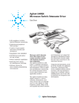
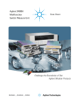
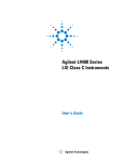
Agilent 34945A, L4445A,
and L4490A/L4491A
Configuration Guide
Contents
Introduction 2
Step 1 Supported Agilent Switches and Attenuators 2
Step 2 Distribution Boards, Bracket Kits, and Cable Kits
5
Bracket and Cable Kit Usage 5
RF Cable and Connector Suppliers
6
Step 3 Switch/Attenuator Driver Instruments and Platforms
6
The 34945A and L4445A Microwave Switch/Attenuator Drivers
6
The L4490A/L4491A RF Switch Platforms 6
System Interconnections Defined
9
L4490A and L4491A RF Switch Platform Product Options 10
L4490A/L4491A Bracket Layout Guidelines
10
Internal/External Power Supply Considerations
11
Internal Supply
11
External Supply
12
System Configuration Chart
13
Related Agilent Literature
13
Introduction
RF/Microwave switches are used in a
wide variety of applications ranging from
DC to over 50 GHz. These applications can
include:
• Wireless Communications,
• Broadband CATV,
• Communication Satellites,
• Test and Measurement
Equipment,
• Electronic Radar
and Defense Systems,
•Avionics,
• Medical Electronics,
• Space Programs.
High Frequency measurement systems
can be configured to route RF/Microwave
signals in a variety
of configurations including:
• Selection from multiple signal sources to
a single output,
• Selection of multiple input signals to a
single measurement instrument,
• Transfer switching to insert or remove a
device in a signal path,
• Matrix switching of multiple inputs and
outputs.
2
Agilent Technologies is a leader in
providing RF/Microwave switching solutions. Agilent’s solutions include both RF/
Microwave switch modules and switch
driver instruments that control discreet
(external) switches and attenuators physically located at the site of the device under
test (DUT) or application.
The purpose of this configuration guide
is to introduce you to the features of the
Agilent 34945A, L4445A, and L4490A/
L4491A family of RF/Microwave switching
instruments, and to assist you in the three
step process of selecting and configuring
your Agilent system:
Step 1: Select the switches/
attenuators and their options for your
application.
Step 2: Determine the type and number
of distribution boards required, and the
bracket and cable kits required.
Step 3: Select the switch driver
instrument or switch platform you plan to
use.
Step 1
Supported Agilent Switches
and Attenuators
The Agilent 34945A and L4445A
Microwave Switch/Attenuator Drivers and
the L4490A/L4491A RF Switch Platform
support virtually any RF/Microwave switch
or attenuator.
Table 1, shown on the following page, is
a list of commonly used and supported
Agilent switches and attenuators with
their recommended options. Use Table 1 to
locate your switch(es)/attenuator(s) and
the accessories required. You may find it
necessary to refer to the table frequently
as you work through this guide.
Note that the switches, attenuators, and
accessories shown in Tables 1
and 2 are not included with the
instrumentation and must be ordered
separately!
Use the chart on page 13 to track
your selections as you determine your
configuration.
Table 1. Common Agilent RF/Microwave Switches and Attenuators
Switch
model
Description
Frequency
range
Reference
document
number 1
N1810UL
N1810TL
N1811TL
N1812UL
87104A
87104B
87104C
Un-terminated latching 3-port (SPDT)
Terminated latching 3-port (SPDT)
Terminated latching 4-port (bypass)
Un-terminated latching 5-port
SP4T 4-port latching, terminated
SP4T 4-port latching, terminated
SP4T 4-port latching, terminated
DC – 2, 4, 20,
or 26.5 GHz
5968-9653E
DC – 4 GHz
DC – 20 GHz
DC – 26.5 GHz
5091-3366E
87106A
87106B
87106C
SP6T 6-port latching, terminated
SP6T 6-port latching, terminated
SP6T 6-port latching, terminated
DC – 4 GHz
DC – 20 GHz
DC – 26.5 GHz
87106P
Low PIM Switch, SP6T 6-port,
latching, terminated
Low PIM Switch, SP6T 6-port,
latching, terminated
Low PIM Switch, SP6T 6-port,
latching, terminated
DC - 4 GHz
DC – 20 GHz
DC – 20 GHz
5965-7841E
87406-80005
87204A
87204B
87204C
6-port matrix, terminated
Low PIM Switch, 6-port matrix,
terminated
SP4T 4-port latching, terminated
SP4T 4-port latching, terminated
SP4T 4-port latching, terminated
DC – 4 GHz
DC – 20 GHz
DC – 26.5 GHz
5965-3309E
87206A
87206B
87206C
SP6T 6-port latching, terminated
SP6T 6-port latching, terminated
SP6T 6-port latching, terminated
DC – 4 GHz
DC – 20 GHz
DC – 26.5 GHz
87606B
87606Q
DC – 20 GHz
DC – 20 GHz
5965-7842E
87606-80005
87222C
87222D
87222E
6-port matrix, terminated
Low PIM Switch, 6-port matrix,
terminated
4-port transfer
4-port transfer
4-port transfer
DC – 26.5 GHz
DC – 40 GHz
DC – 50 GHz
5968-2216E
87222R
L7104A
L7104B
L7104C
Low PIM Switch, 4-port transfer
SP4T 4-port latching, terminated
SP4T 4-port latching, terminated
SP4T 4-port latching, terminated
DC- 26.5 GHz
DC – 4 GHz
DC – 20 GHz
DC – 26.5 GHz
87222-80007
5989-6030EN
L7106A
L7106B
L7106C
SP6T 6-port latching, terminated
SP6T 6-port latching, terminated
SP6T 6-port latching, terminated
DC – 4 GHz
DC – 20 GHz
DC – 26.5 GHz
L7204A
L7204B
L7204C
SP4T 4-port latching, un-terminated
SP4T 4-port latching, un-terminated
SP4T 4-port latching, un-terminated
DC – 4 GHz
DC – 20 GHz
DC – 26.5 GHz
L7206A
L7206B
L7206C
L7222C
SP6T 6-port latching, un-terminated
SP6T 6-port latching, un-terminated
SP6T 6-port latching, un-terminated
4-port transfer latching, terminated
DC – 4 GHz
DC – 20 GHz
DC – 26.5 GHz
DC – 26.5 GHz
8762A
8762B
8762C
Terminated latching 3-port (SPDT)
Terminated latching 3-port (SPDT)
Terminated latching 3-port (SPDT)
DC – 4 GHz
DC – 18 GHz
DC – 26.5 GHz
8763A
8763B
8763C
Terminated latching 4-port (transfer) DC – 4 GHz
Terminated latching 4-port (transfer) DC – 18 GHz
Terminated latching 4-port (transfer) DC – 26.5 GHz
8764A
8764B
8764C
Terminated latching 5-port
Terminated latching 5-port
Terminated latching 5-port
DC – 4 GHz
DC – 18 GHz
DC – 26.5 GHz
8762F
75 ohms Terminated (SPDT)
DC – 4 GHz
87106Q
87106R
87406B
87406Q
DC - 20 GHz
Coil voltage
option
124
Position
DC
Distribution
indicator connector board [number
option
option
of switches/
board]
402/403 2
201
(DB9F)
Bracket kit 3
(Cable kit) 3
Y1150A [8]
Y1152A [2]
Y1154A [6]
Y1170A: L4491A
Y1171A: L4490A
(Y1157A)
Y1151A [2]
Y1172A
(Y1159A)
024: 24 VDC
161
87104-80017 T24: TTL/5 V
Included
CMOS
(16-pin DIP)
compatible
DC - 26.5 GHz
5989-6084EN
161
(16-pin DIP)
Y1152A [1]
Y1172A
(Y1159A)
Included
Included
024: 24 VDC
N/A
Included
Included
161
(16-pin DIP)
Y1154A [2]
Y1173A
(Y1158A)
024
Included
161
(16-pin DIP)
Y1151A [2]
Y1172A
(Y1159A)
Included
Included
161
(16-pin DIP)
Y1154A [2]
Y1173A
(Y1158A)
024
N/A
Solder
terminals
(standard)
Y1155A [8]
Y1170A: L4491A
Y1171A: L4490A
24 VDC
5952-1873E
5964-3704E
3
Table 1. Common Agilent RF/Microwave Switches and Attenuators, continued
Switch
model
Description
Frequency
range
Reference
document
number 1
8765A
8765B
8765C
8765D
Coaxial (SPDT),SMA
Coaxial (SPDT),SMA
Coaxial (SPDT),3.5 mm
Coaxial (SPDT),2.4 mm
DC – 4 GHz
DC – 20 GHz
DC – 26.5 GHz
DC – 40 GHz
5952-2231E
8765F
8766K
8767K
8768K
8769K
8767M
8768M
8769M
U9397A
U9397C
Coaxial (SPDT), 75 ohm, SMB
Coaxial (SP3T)
Coaxial (SP4T)
Coaxial (SP5T)
Coaxial (SP6T)
Coaxial (SP4T)
Coaxial (SP5T)
Coaxial (SP6T)
8 GHz Solid State
18 GHz Solid State
5091-2679E
5959-7831
84904K
84904L
11 dB max, 1 dB steps, 4 sections
DC – 4 GHz
DC – 26.5 GHz
DC – 26.5 GHz
DC – 26.5 GHz
DC – 26.5 GHz
DC – 50 GHz
DC – 50 GHz
DC – 50 GHz
300 kHz-8 GHz
300 kHz–18
GHz
DC – 26.5 GHz
DC – 40 GHz
84906K
84906L
90 dB max, 10 dB steps, 4 sections
DC – 26.5 GHz
DC – 40 GHz
84907K
84907L
70 dB max, 10 dB steps, 3 sections
DC – 26.5 GHz
DC – 40 GHz
84904M
84905M
84908M
11 dB max, 1 dB steps, 4 sections
60 dB max, 10 dB steps, 3 sections
65 dB max, 5 dB steps, 4 sections
DC – 50 GHz
8494G
8494H
11 dB max, 1 dB steps, 4 sections
DC – 4 GHz
DC – 18 GHz
8495G
8495H
70 dB max, 10 dB steps, 3 sections
DC – 4 GHz
DC – 18 GHz
8496G
8496H
110 dB max, 10 dB steps, 4 sections DC – 4 GHz
DC – 18 GHz
8495K
70 dB max, 10 dB steps, 4 sections
DC – 26.5 GHz
8497K
90 dB max, 10 dB steps, 4 sections
DC – 26.5 GHz
5988-2477EN
5989-6088EN
Coil voltage
option
Position
DC
Distribution
indicator connector board [number
option
option
of switches/
board]
Bracket kit 3
(Cable kit) 3
324
n/a
Solder
terminals
(with 324)
Y1155A [8]
Y1170A: L4491A
Y1171A: L4490A
024
n/a
060
(12-pin
Viking)
Y1155A [2]
Y1155A [1]
Y1175A
024
n/a
10-pin DIP
Y1153A [2]
Y1175A
(Y1158A)
Included
n/a
Solder
terminals
Y1155A [8]
Y1170A: L4491A
Y1171A: L4490A
24 V
(standard)
Included
10-pin DIP
(standard)
Y1153A [2]
Y1174A
(Y1158A)
024
Included
10-pin DIP
(standard)
Y1153A [2]
Y1174A
(Y1158A)
24 V
(standard)
Included
12-pin Viking
(standard) Y1153A [2]
Y1175A
5963-6944
5988-2475EN
4
1 Product and technical overviews for the switches and attenuators
listed can be obtained by document number from the Agilent RF &
Microwave Test Accessories web site. Go to http://www.agilent.
com/find/accessories, select ‘RF & Microwave Test Accessories,’ and
search for the document number. Additional information can also be
found in the ‘RF and Microwave Test Accessories Catalog’ accessible
from this site. If viewing this document on-line, click on the reference
document link.
3 Bracket kits apply to the L4490A and L4491A. These kits include
pre-assembled control cables and hardware for mounting switches/
attenuators to the brackets and the bracket assemblies to the L4490A
and L4491A RF Switch Platforms. Each bracket kit supports multiple
switches (Table 2). The Cable-only kits are primarily used with the
34945A and L4445A, but can also be used with the L4490A and L4491A.
These cables must be assembled and each kit contains material to
build multiple cables (Table 2).
2 Starting in June 2010, the current interrupt function (formerly Option
403) is a standard feature for these switches. The serial number
information below shows which switch units have the current interrupt
function included as standard.
4 Information on these attenuators plus additional information on
other attenuators can be found in the latest version of the ‘RF and
Microwave Test Accessories Catalog.’
N1810UL: Serial numbers MY07244672 and later
N1810TL: Serial numbers MY07247927 and later
N1811TL: Serial numbers MY07244660 and later
N1812UL: Serial numbers MY07240668 and later
4
Step 2
Distribution Boards, Bracket
Kits, and Cable Kits
Switches and attenuators are connected
to the Agilent 34945A and L4445A
Microwave Switch/Attenuator Drivers and
the L4490A/L4491A RF Switch Platform
through distribution boards installed
on the 34945EXT module (see System
Interconnections Defined).
There are five distribution boards (Y1150A
– Y1154A) designed to allow Agilent’s
most popular switches and attenuators
to be driven directly. A sixth distribution
board, the Y1155A, is designed to drive
virtually any switch or attenuator by
providing screw terminals to connect to
relay coils and position indicators.
The distribution board required for each
switch/attenuator model and the number
of switches/attenuators
supported per board (shown in brackets [ ])
are listed in Table 1.
The Y115x distribution boards are passive;
they only provide socket headers or screw
terminals that interface external devices to
the 34945EXT. The distribution boards do
provide access to position feedback signals
that can be used to drive LED’s to visually
represent a signal path, for example.
Bracket and Cable Kit Usage
There are six bracket kits and three cable
kits available separately for switch/
attenuator installation and control (Table
1). The number of switches/attenuators
supported per kit is summarized in Table 2.
The bracket kits apply to the L4490A and
L4491A Each bracket kit contains hardware
for mounting the switch to the bracket and
for mounting the bracket assembly in the
chassis.
The cable-only kits are primarily used with
the 34945A and L4445A, but can also be
used with the L4490A and L4491A.
Figure 1. The Y1150A – Y1155A Distribution Boards
Table 2. Bracket and Cable Kit Usage
Kit
number
Number of Control
switches
cable
supported included
Usage
Notes
L4490A/L4491A Bracket Kits
Y1170A
5
Yes
L4491A
Five brackets per kit. Cable is pre-assembled.
Y1171A
5
Yes
L4490A
Five brackets per kit. Cable is pre-assembled.
Y1172A
5
Yes
L4490A
L4491A
Five brackets per kit. Cable is pre-assembled.
Y1173A
6
Yes
L4490A
L4491A
Three brackets per kit. Two switches per bracket.
Cable is pre-assembled.
Y1174A
5
Yes
L4490A
L4491A
Five brackets per kit. Cable is pre-assembled.
Y1175A
5
No
L4490A
L4491A
Five brackets per kit. No cable provided.
34945A/L4445A Cable Kits
Y1157A
4
—
34945A
L4445A
L4490A
L4491A
Cable only – must be assembled.
See Table 1 for applicable switches and attenuators.
Y1158A
2
—
34945A
L4445A
L4490A
L4491A
Cable only – must be assembled.
See Table 1 for applicable switches and attenuators.
Y1159A
2
—
34945A
L4445A
L4490A
L4491A
Cable only – must be assembled.
See Table 1 for applicable switches and attenuators.
5
RF Cable and Connector Suppliers
There are several suppliers for RF cables
and connectors for the switches/attenuators used within the L4490A and L4491A
RF switch platforms. For convenience,
three of these suppliers are listed below:
Pasternack Enterprises, Inc.
http://www.pasternack.com
Micro-Coax®
http://www.micro-coax.com
S. M. Electronics L.L.C.
http://www.smelectronics.us
Step 3
Switch/Attenuator Driver
Instruments and Platforms
For many applications, it is necessary
to locate the switching device as close as
possible to the DUT. Discrete switches and
attenuators are used for
this purpose. Optimum use of these
devices requires switch/attenuator drivers
that are specifically designed to provide
the following features:
The 34945A and L4445A
Microwave Switch/Attenuator
Drivers
For test systems requiring additional functionality, consider the 34945A Microwave
Switch/Attenuator Driver module. The
34945A is a one-slot, plug-in module used
with the Agilent 34980A Multifunction
Switch/Measure Unit. The 34980A offers
a 6.5 digit DMM, and supports a host of
switching and control modules. LAN, GPIB,
and USB interfaces plus a full-feature front
panel are standard with the 34980A.
For dedicated or stand-alone RF/
Microwave switching applications, there
is the L4445A Microwave Switch/
Attenuator Driver instrument. The L4445A
is a 1U, ½-rack LXI (LAN eXtensions for
Instrumentation) version of the 34945A.
LXI is an instrumentation standard for
devices that use the Ethernet (LAN) as
their primary communications interface.
The 1U, ½-rack reference refers to the
L4445A’s physical size relative to standard
EIA rack cabinet dimensions.
• Digital Outputs to drive relay coils in
either pulsed or continuous drive mode,
Understanding what is included when
the 34945A or L4445A is ordered and
those accessories which must be ordered
separately, simplifies the configuration
process.
• Digital Outputs that can drive switch
position feedback LEDs,
The following items are included with the
34945A and L4445A at shipment:
• Digital Inputs to sense the position of
the switches,
• Power distribution between the power
supply, switches, and control logic,
• Report generation that indicates how
often switches have been actuated.
These features are standard with the
Agilent 34945A and L4445A Microwave
Switch/Attenuator Drivers and the
L4490A/L4491A
RF Switch Platform.
The L4490A/L4491A RF Switch
Platforms
Also for dedicated or stand-alone
RF/Microwave switching applications
are the Agilent L4490A and L4491A RF
Switch Platforms. The 2U L4490A
and 4U L4491A allow the mounting of
switches and attenuators within a chassis.
Included with the L4490A and L4491A at
shipment are:
Item
5061-0701
Description
LAN cross-over cable for
direct PC to L4490A/L4491A
connection.
L4490-61603 9-pin D-SUB extension cable
for supplying +24 V to the
34945EXT module.
34945EXT
Extender module
(included in the L4490A and
L4491A chassis).
The internal configuration and typical
system connections are shown in Figure 3.
Item
5061-0701
Description
LAN cross-over cable for
direct PC to 34945A/L4445A
connection.
8121-1289* 9-pin D-SUB extension cable
for supplying +24 V to the
34945EXT module.
34945EXT Extender module
(one is automatically added
to each 34945A and L4445A
ordered.)
8121-1339 CAT-5E RJ45 cable
(included with the 34945EXT
for communication between
extender modules).
Typical connections of these system
components are shown in Figure 2.
6
*Not available from Agilent. Can be purchased
locally or from the vendor L-COM (http://
www.l-com.com) as part number CRMN9MF-10.
LAN
hub/switch
* = standard LAN cables
*
*
or
LAN cross-over cables for direct
PC – 34980A/L4445A connection
if PC is non Auto-MDIX
(cable p/n 5061-0701)
Agilent 34980A
Agilent L4445A
Ag ilen t Te ch no lo gie s
I/O interfaces:
LAN
GPIB (optional)
L4445AM ic row av e S witch/A tte nuator Dr iv er
CO NT RO L BUS
AT TN
LAN
PWR
LAN
Re set
I/O interfaces:
LAN (shown)
GPIB
USB
34945A Plug-in module
+24 V
8121-1289
+24 V
1
2
3
4
E X P AN S IO N B US
8121-1289
P O RT2
P O RT1
Master 34945EXT connects to 1st slave
through Expansion Port 1. Expansion ports
on slaves are interchangesable.
N OT E T HE RN E T
!
S E E MA N UA L
34945EXT #1
(master)
+V
E X T E RN AL
P O W E R IN P PU T
30 V D C MA X
1
2
3
4
I/ O A C CE S S
8121-1339
1
2
3
4
E X P AN S IO N B US
P O RT2
P O RT1
N OT E T HE RN E T
!
S E E MA N UA L
34945EXT #2
(1st slave)
+V
E X T E RN AL
P O W E R IN P PU T
30 V D C MA X
1
2
3
4
I/ O A C CE S S
+V
Ext power
24V/12V/5V
Up to eight 34945EXT modules including the master per 34945A or L4445A
Figure 2. 34945A and L4445A External Connections
7
LAN
hub/switch
*
or
* = standard LAN cables
*
LAN cross-over cables for direct PC –
L4490A/L4491A connection if PC is non Auto-MDIX
Cable p/n 5061-0701
Agilent L4491A
+24 V supplied
from L4491A
I/O interfaces:
LAN
GPIB (optional)
+24 V supplied
from L4491A
L4491A Option 002
34945EXT #2
1st slave
34945EXT #1
(master)
*
Agilent L4490A
+24 V supplied
from L4490A
Master 34945EXT connects to 1st slave
through Expansion Port 1. Expansion ports
on slaves are interchangeable.
External power supply required for all slave
34945EXT modules EXTERNAL to the L4490A/L4491A.
EXTERNAL
POWER INPUT
30 VDC MAX
34945EXT #1
(master)
Up to seven slave 34945EXT modules per L4490A or L4491A
Figure 3. L4490A and L4491A Internal Configuration and Typical Connections
8
+V
System Interconnections
Defined
The following sections describe the
interconnections and components of the
34945A, L4445A, and L4490A/L4491A as
shown in Figures 2 and 3.
PC to 34945A, L4445A, or L4490A/
L4491A
When connecting the PC directly to the
34980A (34945A), L4445A, or L4490A/
L4491A, the LAN cross-over cable (p/n
5061-0701) provided with the instruments
is used. If your PC supports Auto-MDIX
or contains a LAN card with Gigabit data
transfer rates, the cross-over cable is
not required. A standard LAN cable may
be used instead. For network configurations that include a LAN switch or router
between the PC and the instruments,
standard LAN cables are used.
Connections from the PC to the 34980A
(34945A) are also available through the
34980A GPIB and USB ports. Connection
via the optional GPIB interface is also
available for the L4445A and L4490A/
L4491A. However, access to the instrument Web interfaces is only available
through the LAN connection (see the
product user’s guide).
34945A, L4445A, or L4490A/L4491A
to 34945EXT
As described in Step 2, Microwave
switches/attenuators are connected to
the 34945A, L4445A, and L4490A/L4491A
through distribution boards (Y1150A
– Y1155A) installed on the 34945EXT
module. The 34945EXT is divided into four
banks (1–4) organized by channel number.
Any distribution board may be installed in
any bank, and multiple distribution boards
of the same type may be installed on the
same 34945EXT module.
Each 34945A or L4445A configuration must
contain at least one 34945EXT module (a
“master”) with limits on the configuration
as follows:
• up to eight 34945EXT modules allowed
per 34980A mainframe which can
consist of eight 34945A modules
each with one 34945EXT module, a
single 34945A module with up to eight
34945EXT modules, or any combination
in between,
• up to eight 34945EXT modules allowed
per L4445A.
The 34945A and L4445A are connected
to the master 34945EXT using the 9-pin
D-Sub extension cable (8121-1289) through
which +24 V is also supplied.
A (master) 34945EXT module is built into
the L4490A and L4491A chassis. Up to
seven 34945EXT modules (in addition
to the master) are allowed per L4490A
and L4491A. A second 34945EXT module
(the first slave) is available in the L4491A
chassis as Option 002.
34945EXT to 34945EXT
Multiple (slave) 34945EXT modules are
connected through the expansion bus
ports using standard (i.e. non cross-over)
LAN cables. A LAN cable (p/n 8121-1339)
is included with each 34945EXT for this
purpose. The master EXT module must be
connected to the first slave module via the
(master’s) Expansion Bus Port 1, and either
Port 1 or Port 2 of the slave EXT module.
The expansion ports on the slave modules
are interchangeable.
34945EXT to External Power Supplies
All slave 34945EXT modules and those
external to the L4490A or L4491A chassis
must use an external power supply or
supplies. The 34945EXT can only support
one external voltage level (+24 V, +12
V, +5 V) at a time which applies to all
distribution board banks on the 34945EXT.
An external supply can also be used with
the master 34945EXT.
Distribution Board Channel
Numbering Schemes
The channel numbers associated with
each bank on the 34945EXT are shown in
the following chart. The channel syntax
for the 34980A (34945A), L4445A, and
L4490A/L4491A is also shown.
Bank
Bank 1
Bank 2
Bank 3
Bank 4
Channels
(lower)
01 – 08
21 – 28
41 – 48
61 – 68
Channels
(upper)
11 – 18
31 – 38
51 – 58
71 – 78
•34945A
<slot #> <ext #> <ch #>
- slot #: 1-8 (34980A)
- ext # : 1-8 (34945EXT)
- ch #: see chart
•L4445A
<1> <ext #> <ch #>
- ext # : 1-8 (34945EXT)
- ch #: see chart
•L4490A/L4491A
<1> <ext #> <ch #>
- ext # : 1-8 (34945EXT)
- ch #: see chart
34945EXT modules are numbered
according to their position in the daisychain sequence relative to the master
34945EXT which is ext # 1.
System Diagnostics
Often the most common problems with
switches/attenuators connected to the
34945EXT through distribution boards
are related to the switch and attenuator
cables. A seventh distribution board, the
Y1156A Verification Board, is used to
provide visual confirmation of the signal
path from the PC to distribution board
banks
1–4. Verifying the path from the PC to a
selected bank helps isolate suspected
problems in the entire path from PC to
switch.
Many Agilent switches contain position
indicator options that allow for electronic
verification of the switch position. The
34945EXT contains circuitry to detect
these signals, and the Y1156A diagnostic
board can also be used to test the
functioning of this circuitry.
9
L4490A and L4491A RF Switch
Platform Product Options
There are five product options available
for the L4491A and one option available
for the L4490A. All options are factory
installed and must be specified at the time
of order. The product options include:
L4491A
• Option 001: multiport front panel. Front
panel modification for mounting up
to eight multiport switches. Includes
mounting hardware. Switch cables must
be ordered separately (Y1159A – Table
1).
Figure 4. L4490A/L4491A Product Option Locations
• Option 002: Adds an additional
34945EXT module internal to the L4491A
chassis (Figure 3).
• Option 004: Adds 16-bit digital IO and 28
bits of relay drive lines.
• Option 005: switch mounting – bays
(default option)
• Option 006: switch mounting – bottom
tray
L4490A
• Option 004: Adds 16-bit digital IO and 28
bits of relay drive lines.
L4490A/L4491A Bracket
Layout Guidelines
Switches installed in the L4490A platform
or in the L4491A platform with Option 006
can be mounted in any orientation that
optimizes or simplifies switch or attenuator
wiring.
For the L4491A with default
Option 005, switches and attenuators
may be mounted in any of the “bays” and
in any combination. Figure 5 shows the
typical number of given brackets (Y1170A –
Y1175A) that can be installed in a bay.
Figure 5. L4491A Mounting Brackets per Bay
10
Internal/External Power
Supply Considerations
As shown in Figures 2 and 3, the channel
drive source for the master 34945EXT
is provided through the internal +24 V
power supply of the 34945A, L4445A, and
L4490A/L4491A. If necessary, external
supplies can be used. For either case, the
supply must meet the quiescent (continuous) and switching current requirements
of the switches in your application.
Internal Supply
When using the internal +24 V supply
of the 34945A or L4445A, the quiescent
current draw must not exceed 100 mA,
with a switching pulse current that does
not exceed 200 mA. The duration of the
switching pulse must be < 15 ms with a
25% duty cycle. The remainder of the duty
cycle (75%) allows recovery time for the
supply to provide the next pulse.
For the L4490A/L4491A, the quiescent and
switching currents from the supply must
not exceed the supply’s specification of
600 mA continuous.
When current limits are exceeded,
overcurrent conditions can occur which
shuts down the internal supply. When this
happens, you must remove the device/
condition causing the overcurrent and
reset or cycle power on the instrument.
The quiescent current requirement of
the 34945EXTs themselves is accounted
for by the internal supply rating and is
not included in quiescent current and
switching current calculations. Only the
specified currents (quiescent, switching) of
the switch must be considered.
As an example, the Agilent 87104/87106A,
B, C coaxial switches specify the following:
Supply current (switching: pulse width = 15 ms:Vcc = 24 VDC): 200 mA Nom
Supply current (quiescent): 50 mA Max
Using the internal +24 V supply,
the current required for actuating a
87104/87106 switch is:
[87104/87106 quiescent current] + [87104/87106 switching current]
[50 mA]
= 250 mA
+
[200 mA]
(15 ms pulse, 50 mA quiescent)
The number of switches available and their
varying power requirements often make
it difficult to determine if the capacity of
the 34945A, L4445A, or L4490A/L4491A
internal +24 V supply will be exceeded. If
overcurrent conditions occur repeatedly
the use of an external power supply may
be required. Refer to the product user
manuals for more information.
11
External Supply
Each 34945EXT module is limited to 2 A
continuous current from an externally
connected power supply (4.75 V to 30 V).
The actual amount of power required by
each EXT module depends on the types of
switches used.
When using an external power supply
with either the master 34945EXT module
or slave 34945EXT modules (required),
the supply must be able to provide the
quiescent current requirement of the EXT
modules, plus the quiescent and switching
currents of the switches themselves.
The power requirement of the 34945EXT
is 1.2 W. For supported external supply
voltages of 24 V,
12 V, and 5 V, the current required for a
single EXT module is as follows:
current = power / voltage
Remember that the external supply must
also meet the quiescent and switching
current requirements of the switch. Using
the Agilent 87104/87106A, B, C coaxial
switches from the internal supply example,
the switch specifications again are:
Supply current (switching: pulse width =15 ms:Vcc = 24 VDC): 200 mA Nom
Supply current (quiescent): 50 mA Max
The quiescent current required for the
34945EXT module is:
[34945EXT quiescent current from 24 V]
[24 V: 1.2 W / 24 V = 50 mA]
Therefore, the current required from an
external supply for actuating a single
87104/87106 switch on a single 34945EXT
module is:
24 V: 1.2 W / 24 V = 50 mA
12 V: 1.2 W / 12 V = 100 mA
5 V: 1.2 W / 5 V = 240 mA
[34945EXT quiescent current from 24 V] + [switch quiescent current] + [switching current]
[24 V: 1.2 W / 24 V = 50 mA]
+
[50 mA]
+
[200 mA]
= 300 mA (15 ms pulse, 100 mA quiescent)
If multiple 34945EXT modules are driven
by a single external supply, the power
required from the supply increases by 1.2
W for each EXT module present. Thus, if
two EXT modules are driven by a single
supply, the power value in the equations
becomes 2.4 W – doubling the current
requirement.
12
In summary, when using an external
supply, the current calculations must
include the quiescent current requirement of the 34945EXT and the quiescent
current requirement of each switch. These
quantities are then added to the switching
(pulse) current requirement of the device.
System configuration chart
Switch/
attenuator
Quantity
Options
* coil
* voltage
* connector
Distribution boards
Quantity
Bracket kit or
cable kit
Related Agilent Literature
Data sheets
Application notes
• Agilent 34980A Multifunction Switch/
Measure Unit
5989-1437EN
• Test System Signal Switching, AN 1441-1
5988-8627EN
http://cp.literature.agilent.com/
litweb/pdf/5988-8627EN.pdf
http://cp.literature.agilent.com/
litweb/pdf/5989-1437EN.pdf
• Agilent L4445A Microwave/Attenuator
Switch Driver
5989-4828EN
http://cp.literature.agilent.com/
litweb/pdf/5989-4828EN.pdf
• Agilent L4490A/L4491A RF Switch
Platform
5989-7857EN
http://cp.literature.agilent.com/
litweb/pdf/5989-7857EN.pdf
• Benefits of a Switch/Measure Unit
for Data Acquisition and Electronic
Functional Test
5989-1481EN
http://cp.literature.agilent.com/
litweb/pdf/5989-1481EN.pdf
For additional information please visit:
http://www.agilent.com/find/34980A
http://www.agilent.com/find/L4445A
http://www.agilent.com/find/L449xA
http://www.agilent.com/find/L4490A
http://www.agilent.com/find/L4491A
• 34980A Multifunction Switch/Measure
System Modules Applications that
benefit from specific module features/
functions
5989-2371EN
http://cp.literature.agilent.com/
litweb/pdf/5989-2371EN.pdf
13
www.agilent.com
www.agilent.com/find/34980a
myAgilent
myAgilent
www.agilent.com/find/myagilent
A personalized view into the information most relevant to you.
For more information on Agilent
Technologies’ products, applications or
services, please contact your local Agilent
office. The complete list is available at:
www.lxistandard.org
www.agilent.com/find/contactus
LAN eXtensions for Instruments puts the power of Ethernet and the
Web inside your test systems. Agilent is a founding member of the
LXI consortium.
Americas
Three-Year Warranty
www.agilent.com/find/ThreeYearWarranty
Beyond product specification, changing the ownership experience.
Agilent is the only test and measurement company that offers
three-year warranty on all instruments, worldwide.
Canada
Brazil Mexico
United States
(877) 894 4414
(11) 4197 3600
01800 5064 800
(800) 829 4444
Asia Pacific
Agilent Solution Partners
Australia 1 800 629 485
China
800 810 0189
Hong Kong 800 938 693
India 1 800 112 929
Japan
0120 (421) 345
Korea
080 769 0800
Malaysia 1 800 888 848
Singapore 1 800 375 8100
Taiwan
0800 047 866
Other AP Countries (65) 375 8100
www.agilent.com/find/solutionpartners
Europe & Middle East
Agilent Assurance Plans
www.agilent.com/find/AssurancePlans
Five years of protection and no budgetary surprises to ensure your
instruments are operating to specifications and you can continually
rely on accurate measurements.
Get the best of both worlds: Agilent’s measurement expertise and
product breadth, combined with solution partner convenience.
Belgium 32 (0) 2 404 93 40
Denmark
45 45 80 12 15
Finland
358 (0) 10 855 2100
France
0825 010 700*
*0.125 €/minute
Germany
49 (0) 7031 464 6333
Ireland
1890 924 204
Israel972-3-9288-504/544
Italy
39 02 92 60 8484
Netherlands
31 (0) 20 547 2111
Spain
34 (91) 631 3300
Sweden
0200-88 22 55
United Kingdom 44 (0) 118 927 6201
For other unlisted countries:
www.agilent.com/find/contactus
(BP-01-15-14)
Product specifications and descriptions in
this document subject to change without
notice.
© Agilent Technologies, Inc. 2013, 2014
Published in USA, May 14, 2014
5989-2272EN