1
Keysight Multi-Channel Attenuation
Control Unit:
J7204A 4-channel, DC to 6 GHz
J7204B 4-channel, DC to 18 GHz
J7205A 5-channel, DC to 6 GHz
J7205B 5-channel, DC to 18 GHz
Operating and
Service Manual
Notices
Copyright Notice
© Keysight Technologies 2015
No part of this manual may be reproduced in any form or by any means
(including electronic storage and
retrieval or translation into a foreign
language) without prior agreement and
written consent from Keysight Technologies as governed by United States and
international copyright laws.
Manual Part Number
J7205-90002
Edition
Edition 1, Sept 17, 2015
Printed in:
Printed in Malaysia
Published by:
Keysight Technologies
Bayan Lepas Free Industrial Zone,
11900 Penang, Malaysia
Technology Licenses
The hardware and/or software
described in this document are furnished under a license and may be
used or copied only in accordance with
the terms of such license.
Declaration of Conformity
Declarations of Conformity for this
product and for other Keysight products may be downloaded from the
Web. Go to http://www.keysight.com/
go/conformity. You can then search by
product number to find the latest Declaration of Conformity.
2
U.S. Government Rights
Warranty
The Software is “commercial computer
software,” as defined by Federal Acquisition Regulation (“FAR”) 2.101. Pursuant to FAR 12.212 and 27.405-3 and
Department of Defense FAR Supplement (“DFARS”) 227.7202, the U.S.
government acquires commercial computer software under the same terms
by which the software is customarily
provided to the public. Accordingly,
Keysight provides the Software to U.S.
government customers under its standard commercial license, which is
embodied in its End User License
Agreement (EULA), a copy of which can
be found at http://www.keysight.com/
find/sweula. The license set forth in the
EULA represents the exclusive authority
by which the U.S. government may use,
modify, distribute, or disclose the Software. The EULA and the license set
forth therein, does not require or permit, among other things, that Keysight:
(1) Furnish technical information
related to commercial computer software or commercial computer software
documentation that is not customarily
provided to the public; or (2) Relinquish
to, or otherwise provide, the government rights in excess of these rights
customarily provided to the public to
use, modify, reproduce, release, perform, display, or disclose commercial
computer software or commercial computer software documentation. No
additional government requirements
beyond those set forth in the EULA
shall apply, except to the extent that
those terms, rights, or licenses are
explicitly required from all providers of
commercial computer software pursuant to the FAR and the DFARS and are
set forth specifically in writing elsewhere in the EULA. Keysight shall be
under no obligation to update, revise or
otherwise modify the Software. With
respect to any technical data as
defined by FAR 2.101, pursuant to FAR
12.211 and 27.404.2 and DFARS
227.7102, the U.S. government
acquires no greater than Limited Rights
as defined in FAR 27.401 or DFAR
227.7103-5 (c), as applicable in any
technical data.
THE MATERIAL CONTAINED IN THIS
DOCUMENT IS PROVIDED “AS IS,”
AND IS SUBJECT TO BEING
CHANGED, WITHOUT NOTICE, IN
FUTURE EDITIONS. FURTHER, TO THE
MAXIMUM EXTENT PERMITTED BY
APPLICABLE LAW, KEYSIGHT DISCLAIMS ALL WARRANTIES, EITHER
EXPRESS OR IMPLIED, WITH REGARD
TO THIS MANUAL AND ANY INFORMATION CONTAINED HEREIN, INCLUDING BUT NOT LIMITED TO THE
IMPLIED WARRANTIES OF MERCHANTABILITY AND FITNESS FOR A
PARTICULAR PURPOSE. KEYSIGHT
SHALL NOT BE LIABLE FOR ERRORS
OR FOR INCIDENTAL OR CONSEQUENTIAL DAMAGES IN CONNECTION
WITH THE FURNISHING, USE, OR
PERFORMANCE OF THIS DOCUMENT
OR OF ANY INFORMATION CONTAINED HEREIN. SHOULD KEYSIGHT
AND THE USER HAVE A SEPARATE
WRITTEN AGREEMENT WITH WARRANTY TERMS COVERING THE MATERIAL IN THIS DOCUMENT THAT
CONFLICT WITH THESE TERMS, THE
WARRANTY TERMS IN THE SEPARATE
AGREEMENT SHALL CONTROL.
Safety Information
CAUTION
A CAUTION notice denotes a hazard. It
calls attention to an operating procedure, practice, or the like that, if not
correctly performed or adhered to,
could result in damage to the product
or loss of important data. Do not proceed beyond a CAUTION notice until
the indicated conditions are fully
understood and met.
WARNING
A WARNING notice denotes a hazard. It
calls attention to an operating procedure, practice, or the like that, if not
correctly performed or adhered to,
could result in personal injury or death.
Do not proceed beyond a WARNING
notice until the indicated conditions are
fully understood and met.
Keysight J7204/5/A/B Operating and Service Manual
Safety Symbols
The following symbols on the instrument and in the documentation indicate
precautions which must be taken to maintain safe operation of the instrument.
Caution, risk of danger (refer to this
manual for specific Warning or Caution
information)
Power line switch is in the STANDBY
position
Frame or chassis (ground) terminal
Alternating current
Protective conductor terminal
Keysight J7204/5/A/B Operating and Service Manual
3
Safety Considerations
Read the information below before using this instrument.
The following general safety precautions must be observed during all phases of
operation, service, and repair of this instrument. Failure to comply with these
precautions or with specific warnings elsewhere in this manual violates safety
standards for design, manufacture, and intended use of the instrument. Keysight
Technologies assumes no liability for the customer’s failure to comply with these
requirements.
Safety earth ground
WARNING
CAUTION
This is a Safety Class I Product (provided with a protective earthing ground
incorporated in the power cord). The mains plug shall be only be inserted in
a socket outlet provided with a protective earth contact. Any interruption of
the protective conductor inside or outside of the product is likely to make
the product dangerous. Intentional interruption is prohibited.
Always use the 3-prong AC power cord supplied with this product. Failure to
ensure adequate earth grounding by not using this cord may cause product
damage and the risk of electrical shock.
Before applying power
Verify that the premises electrical supply is within the range of the instrument. The
instrument has an autoranging power supply.
WARNING
– If this instrument is not used as specified, the protection provided by the
instrument could be impaired. This instrument must be used in a normal
condition (in which all means for protection are intact) only.
– Servicing should only be performed by qualified personnel only. To avoid
electrical shock, do not perform any servicing unless you are qualified to
do so.
4
Keysight J7204/5/A/B Operating and Service Manual
WARNING
– Danger of explosion if battery is incorrectly replaced. Replace only with
the same or equivalent type recommended. Discard used batteries
according to manufacturer’s instructions.
– For continued protection against fire hazard, replace the line fuse only
with the same type and rating. The use of other fuses or material is
prohibited.
– The opening of covers or removal of parts is likely to expose the user to
dangerous voltages. Disconnect the instrument from all voltage sources
before opening.
– No operator serviceable parts inside. Refer servicing to qualified
personnel. To prevent electrical shock, do not remove covers.
– The detachable power cord is the instrument disconnecting device. It
disconnects the mains circuits from the mains supply before other parts
of the instrument. The front panel button is only a standby switch and is
not a LINE switch (disconnecting device).
CAUTION
– The mains wiring and connectors shall be compatible with the connector
used in the premise electrical system. Failure to ensure adequate earth
grounding by not using the correct components may cause instrument
damage and serious injury.
– This instrument is designed for use in Installation Category II and
Pollution Degree 2.
– Before switching on this instrument, make sure the supply voltage is in
the specified range.
– Verify that the premise electrical voltage supply is within the range
specified on the instrument.
– Ventilation Requirements: When installing the instrument in a cabinet,
the convection into and out of the instrument must not be restricted. The
ambient temperature (outside the cabinet) must be less than the
maximum operating temperature of the instrument by 4 °C for every
100 watts dissipated in the cabinet. If the total power dissipated in the
cabinet is greater than 800 watts, forced convection must be used.
Keysight J7204/5/A/B Operating and Service Manual
5
Regulatory Information
Statement of compliance
This instrument has been designed and tested in accordance with
CAN/CSA-C22.2 No. 61010-1-12, UL Std. No. 61010-1 (3rd Edition).
Regulatory markings
The CE mark is a registered trademark
of the European Community. This CE
mark shows that the product complies
with all the relevant European Legal
Directives.
The CSA mark is a registered
trademark of the Canadian
Standards Association.
The RCM mark is a registered
trademark of the Spectrum
Management Agency of Australia. This
signifies compliance with the Australia
EMC Framework regulations under the
terms of the Radio Communication Act
of 1992.
This symbol indicates the time
period during which no hazardous or
toxic substance elements are
expected to leak or deteriorate
during normal use. Forty years is the
expected useful life of the product.
ICES/NMB-001 indicates that this ISM
device complies with the Canadian
ICES-001.
Cet appareil ISM est conforme a la
norme NMB-001 du Canada.
This instrument complies with the
WEEE Directive (2002/96/EC)
marking requirement. This affixed
product label indicates that you
must not discard this electrical or
electronic product in domestic
household waste.
This instrument is Class A suitable for professional use and is
for use in electromagnetic environments outside of the home.
MSIP-REM-KstWNJ7205B
6
Keysight J7204/5/A/B Operating and Service Manual
Waste Electrical and Electronic Equipment (WEEE) Directive 2002/
96/EC
This instrument complies with the WEEE Directive (2002/96/EC) marking
requirement. This affixed product label indicates that you must not discard this
electrical or electronic product in domestic household waste.
Product category:
With reference to the equipment types in the WEEE directive Annex 1, this
instrument is classified as a “Monitoring and Control Instrument” product.
The affixed product label is as shown below.
Do not dispose in domestic household waste.
To return this unwanted instrument, contact your nearest Keysight Service Center,
or visit http://about.keysight.com/en/companyinfo/environment/takeback.shtml
for more information.
Sales and Technical Support
To contact Keysight for sales and technical support, refer to the support links on
the following Keysight websites:
– www.keysight.com/find/attenuators
(product-specific information and support, software and
documentation updates)
– www.keysight.com/find/assist
(worldwide contact information for repair and service)
Keysight J7204/5/A/B Operating and Service Manual
7
THIS PAGE HAS BEEN INTENTIONALLY LEFT BLANK.
8
Keysight J7204/5/A/B Operating and Service Manual
Table of Contents
Safety Symbols . . . . . . . . . . . . . . . . . . . . . . . . . . . . . . . . . . . . . . . . . . . . . 3
Safety Considerations . . . . . . . . . . . . . . . . . . . . . . . . . . . . . . . . . . . . . . . . 4
Safety earth ground . . . . . . . . . . . . . . . . . . . . . . . . . . . . . . . . . . . . . . . 4
Before applying power . . . . . . . . . . . . . . . . . . . . . . . . . . . . . . . . . . . . . 4
Regulatory Information . . . . . . . . . . . . . . . . . . . . . . . . . . . . . . . . . . . . . . . 6
Statement of compliance
. . . . . . . . . . . . . . . . . . . . . . . . . . . . . . . . . .6
Regulatory markings . . . . . . . . . . . . . . . . . . . . . . . . . . . . . . . . . . . . . . 6
Waste Electrical and Electronic Equipment (WEEE) Directive 2002/96/
EC . . . . . . . . . . . . . . . . . . . . . . . . . . . . . . . . . . . . . . . . . . . . . . . . . . . . . 7
Product category:
. . . . . . . . . . . . . . . . . . . . . . . . . . . . . . . . . . . . . . . .7
Sales and Technical Support . . . . . . . . . . . . . . . . . . . . . . . . . . . . . . . . . . 7
1
Introduction
Product Overview . . . . . . . . . . . . . . . . . . . . . . . . . . . . . . . . . . . . . . . . . .16
Key features of the J7204/5/A/B attenuation control unit . . . . . . . .17
Instrument options . . . . . . . . . . . . . . . . . . . . . . . . . . . . . . . . . . . . . . .17
Front and rear panel features . . . . . . . . . . . . . . . . . . . . . . . . . . . . . .18
2
Installation
Initial Inspection . . . . . . . . . . . . . . . . . . . . . . . . . . . . . . . . . . . . . . . . . . .22
Verify the J7204/5/A/B Shipment Contents . . . . . . . . . . . . . . . . . . . . .23
Service and Recalibration . . . . . . . . . . . . . . . . . . . . . . . . . . . . . . . . . . . .23
Related Documentation . . . . . . . . . . . . . . . . . . . . . . . . . . . . . . . . . . . . .23
System Requirements . . . . . . . . . . . . . . . . . . . . . . . . . . . . . . . . . . . . . . .24
Software Installation . . . . . . . . . . . . . . . . . . . . . . . . . . . . . . . . . . . . . . . .25
Operating and Safety Precautions . . . . . . . . . . . . . . . . . . . . . . . . . . . . .26
ESD damage
. . . . . . . . . . . . . . . . . . . . . . . . . . . . . . . . . . . . . . . . . . .26
Connector care and cleaning precautions . . . . . . . . . . . . . . . . . . . .26
3
Specifications
Keysight J7204/5/A/B Operating and Service Manual
9
General Specifications . . . . . . . . . . . . . . . . . . . . . . . . . . . . . . . . . . . . . . 30
Specifications
. . . . . . . . . . . . . . . . . . . . . . . . . . . . . . . . . . . . . . . . . . 30
Power requirements . . . . . . . . . . . . . . . . . . . . . . . . . . . . . . . . . . . . . 31
Physical specifications
. . . . . . . . . . . . . . . . . . . . . . . . . . . . . . . . . . . 32
Mechanical Dimensions . . . . . . . . . . . . . . . . . . . . . . . . . . . . . . . . . . . . . 33
Environmental Specifications . . . . . . . . . . . . . . . . . . . . . . . . . . . . . . . . . 37
4
Operating Guide
Operating Instructions . . . . . . . . . . . . . . . . . . . . . . . . . . . . . . . . . . . . . . 40
Operator’s check . . . . . . . . . . . . . . . . . . . . . . . . . . . . . . . . . . . . . . . . 40
Getting Started with the Soft Front Panel (SFP) . . . . . . . . . . . . . . . . . . 43
Controlling the J7204/5/A/B Attenuation Control Unit . . . . . . . . . . . . 49
Controlling the J7204/5/A/B and making measurements . . . . . . . . 49
LAN connection . . . . . . . . . . . . . . . . . . . . . . . . . . . . . . . . . . . . . . . . . 49
GPIB connection . . . . . . . . . . . . . . . . . . . . . . . . . . . . . . . . . . . . . . . . 52
Programming Guide . . . . . . . . . . . . . . . . . . . . . . . . . . . . . . . . . . . . . . . . 53
SCPI command syntax
. . . . . . . . . . . . . . . . . . . . . . . . . . . . . . . . . . . 53
Commands relevant to the J7204/5/A/B . . . . . . . . . . . . . . . . . . . . . 53
J7204/5/A/B SCPI commands . . . . . . . . . . . . . . . . . . . . . . . . . . . . . 61
Service and Maintenance . . . . . . . . . . . . . . . . . . . . . . . . . . . . . . . . . . . . 63
Service . . . . . . . . . . . . . . . . . . . . . . . . . . . . . . . . . . . . . . . . . . . . . . . . 63
Maintenance . . . . . . . . . . . . . . . . . . . . . . . . . . . . . . . . . . . . . . . . . . . 63
10
Keysight J7204/5/A/B Operating and Service Manual
List of Figures
Figure 1-1
Figure 1-2
Figure 1-3
Figure 3-1
Figure 3-2
Figure 3-3
Figure 3-4
Figure 4-1
Figure 4-2
Figure 4-3
Figure 4-4
Figure 4-5
Figure 4-6
Figure 4-7
Figure 4-8
Figure 4-9
Figure 4-10
J7204/5/A/B attenuation control unit . . . . . . . . . . . . .16
J7204/5/A/B front panel . . . . . . . . . . . . . . . . . . . . . . .18
J7204/5/A/B rear panel . . . . . . . . . . . . . . . . . . . . . . . .20
Mechanical dimensions of the J7204A/B with Type-N
connector . . . . . . . . . . . . . . . . . . . . . . . . . . . . . . . . .33
Mechanical dimensions of the J7204A/B with SMA
connector . . . . . . . . . . . . . . . . . . . . . . . . . . . . . . . . .34
Mechanical dimensions of the J7205A/B with Type-N
connector . . . . . . . . . . . . . . . . . . . . . . . . . . . . . . . . .35
Mechanical dimensions of the J7205A/B with SMA
connector . . . . . . . . . . . . . . . . . . . . . . . . . . . . . . . . .36
Quick-check configuration for the S-parameter test .40
Setting the attenuation value
. . . . . . . . . . . . . . . . . . .42
J7204/5/A/B SFP window . . . . . . . . . . . . . . . . . . . . . .43
J7205x main SFP interface
. . . . . . . . . . . . . . . . . . . . .44
J7204/5/A/B main SFP interface . . . . . . . . . . . . . . . . .46
Errors window . . . . . . . . . . . . . . . . . . . . . . . . . . . . . . . .47
Driver Log window . . . . . . . . . . . . . . . . . . . . . . . . . . . .48
Add LAN instrument . . . . . . . . . . . . . . . . . . . . . . . . . . .50
LAN instrument added . . . . . . . . . . . . . . . . . . . . . . . . .51
GPIB instrument added . . . . . . . . . . . . . . . . . . . . . . . .52
Keysight J7204/5/A/B Operating and Service Manual
11
THIS PAGE HAS BEEN INTENTIONALLY LEFT BLANK.
12
Keysight J7204/5/A/B Operating and Service Manual
List of Tables
Table 1-1
Table 1-2
Table 2-1
Table 3-1
Table 3-2
Table 3-3
Table 3-4
Table 4-1
Table 4-2
J7204/5/A/B connector options . . . . . . . . . . . . . . . . .17
J7204/5/A/B’s state LED definitions . . . . . . . . . . . . . .19
J7204/5/A/B shipment contents . . . . . . . . . . . . . . . . .23
Specifications of the J7204/5/A/B . . . . . . . . . . . . . . .30
Attenuation accuracy of the J7204/5/A/B . . . . . . . . .31
Physical specifications of the J7204/5/A/B
. . . . . . . .32
J7204/5/A/B environmental specifications . . . . . . . . .37
Overview of the main SFP interface . . . . . . . . . . . . . . .44
J7204/5/A/B SCPI commands
. . . . . . . . . . . . . . . . . .61
Keysight J7204/5/A/B Operating and Service Manual
13
THIS PAGE HAS BEEN INTENTIONALLY LEFT BLANK.
14
Keysight J7204/5/A/B Operating and Service Manual
Keysight J7204/5/A/B Attenuation Control Unit
Operating and Service Manual
1
Introduction
Product Overview
16
This chapter provides an overview of the Keysight J7204/5/A/B Multi-Channel
Attenuation Control Unit.
15
1
Introduction
Product Overview
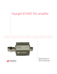
The Keysight J7204A/B and J7205A/B multi-channel attenuation control units are
used for signal attenuation or conditioning. The J7204A/B consists of four
attenuation channels while the J7205A/B consists of five attenuation channels,
whereby the RF signal is routed through the front panel.
The J7204/5/A/B attenuation control unit is made up of a 2U, full-rack chassis.
The J7204A/B is equipped with four sets of 11 dB/110 dB attenuator pairs while
the J7205A/B is equipped with five sets of 11 dB/110 dB attenuator pairs, with a
DC to 6 GHz/18 GHz frequency range.
All external RF connections are SMA (f) or N-Type and are at the front of the unit.
The J7204/5/A/B is controlled through the GPIB or LAN interface. In addition, the
bundled soft front panel provides an alternative virtual interface to control the
J7204/5/A/B.
Figure 1-1
16
J7204/5/A/B attenuation control unit
Keysight J7204/5/A/B Operating and Service Manual
Introduction
1
Key features of the J7204/5/A/B attenuation control unit
– Exceptional 0.03 dB insertion loss repeatability per section for the entire
5 million cycles ensures accuracy and reduces calibration intervals
– Excellent attenuation accuracy and flatness ensure precise measurements
– Multi-channel attenuation path up to five channels enable multi-DUT
measurements at one time
– LAN and GPIB interfaces with soft front panel provide easy connectivity,
programming flexibility, and control
Instrument options
There are two connector options available for the J7204/5/A/B as follows:
Table 1-1
J7204/5/A/B connector options
Option number
Description
J7204A-001
Type-N connector
J7204A-002
SMA connector
J7204B-001
Type-N connector
J7204B-002
SMA connector
J7205A-001
Type-N connector
J7205A-002
SMA connector
J7205B-001
Type-N connector
J7205B-002
SMA connector
Keysight J7204/5/A/B Operating and Service Manual
17
1
Introduction
Front and rear panel features
This section provides an overview of the front and rear panels of the J7204/5/A/B.
CAUTION
Refer to the standard instrument documentation for damage limits to the
ports. Verify that your test setup will not cause those limits to be exceeded.
Front panel
Instrument state LEDs
Standby button
Figure 1-2
J7204/5/A/B front panel
Standby button
Note that this button is Standby only, not a line switch. The main power cord can be used as the system
disconnecting device. It disconnects the mains circuits from the mains supply.
Instrument state
LEDs
When power is applied to the J7204/5/A/B, the J7204/5/A/B enters its power-on sequence which
requires several seconds to complete. The LEDs provide information on the state of the J7204/5/A/B
during power on and during upgrades of the J7204/5/A/B’s firmware. Table 1-2 on page 19 identifies
the J7204/5/A/B’s states based on the color and functionality of the LEDs.
Ports
– For J7204A/B: There are four channels, with two ports per channel: Port 1 and Port 2. Each channel
has one input port and one output port. The front panel RF connector is either SMA (female) or
Type-N.
– For J7205A/B: There are five channels, with two ports per channel: Port 1 and Port 2. Each channel
has one input port and one output port. The front panel RF connector is either SMA (female) or
Type-N.
18
Keysight J7204/5/A/B Operating and Service Manual
Introduction
Table 1-2
1
J7204/5/A/B’s state LED definitions
LED
Color
Instrument state
ATTN
LAN
PWR
Off
Green
Green
Instrument in the “ready” state
LAN connection established
– instrument has an IP address firmware download complete
ATTN
LAN
PWR
flashing
flashing
Green
Power-on/boot-up. ATTN and LAN will flash red and then green
during the power-on self-test.
ATTN
LAN
PWR
Off
Red
Green
No LAN connection due to:
– disconnected LAN cable
– failure to acquire an IP address
– waiting for DHCP-assigned address
ATTN
LAN
PWR
Green (flashing)
Green
Green
Instrument busy state
– firmware download (LAN LED red if download over GPIB)
– lengthy instrument operation in progress
ATTN
LAN
PWR
Red (flashing)
Green
Green
Instrument programming error or self-test error.
Error queue is read using SYSTem:ERRor?
ATTN
LAN
PWR
Off
Green (flashing)
Green
Instrument identification. Activated from the instrument’s Web
interface:
– ON: Turn on the Front Panel Interface Indicator
– OFF: Turn off the Front Panel Interface Indicator
Keysight J7204/5/A/B Operating and Service Manual
19
1
Introduction
Rear panel
GPIB
connector
Figure 1-3
LAN
Line input
J7204/5/A/B rear panel
GPIB connector
This connector allows the J7204/5/A/B to be connected directly to a controller.
LAN
The J7204/5/A/B is controlled over the Local Area Network (LAN).
Line input
The line input contains the power cord receptacle. Install the J7204/5/A/B so that the detachable power
cord is readily identifiable and is easily reached. The detachable power cord is the instrument
disconnecting device. It disconnects the mains circuits from the mains supply before other parts of the
instrument. The front panel switch is only a standby switch and is not a LINE switch. Alternatively, an
externally installed switch or circuit breaker (which is readily identifiable and is easily reached by the
operator) may be used as a disconnecting device.
CAUTION
20
Always use the 3-prong AC power cord supplied with the J7204/5/A/B.
Failure to ensure adequate grounding by not using this cord may cause
damage to the J7204/5/A/B.
Keysight J7204/5/A/B Operating and Service Manual
Keysight J7204/5/A/B Attenuation Control Unit
Operating and Service Manual
2
Installation
Initial Inspection 22
Verify the J7204/5/A/B Shipment Contents
Service and Recalibration 23
Related Documentation 23
System Requirements 24
Software Installation 25
Operating and Safety Precautions 26
23
This chapter provides you important information on how to check and prepare
your instrument for operation.
21
2
Installation
Initial Inspection
1 Unpack and inspect the shipping container and its contents throughly to
ensure that nothing was damaged during shipment. If the shipping container
or cushioning material is damaged, the contents should be checked both
mechanically and electrically.
– Check for mechanical damage such as scratches or dents.
– Procedures for checking electrical performance are given under “Operator’s
check” on page 40.
2 If the contents are damaged or defective, contact your nearest Keysight
Technologies Service and Support Office. Refer to “Sales and Technical
Support” on page 7 of this manual. Keysight Technologies will arrange for
repair or replacement of the damaged or defective equipment. Keep the
shipping materials for the carrier’s inspection.
3 If you are returning the instrument under warranty or for service, repackaging
the instrument requires original shipping containers and material or their
equivalents. Keysight Technologies can provide packaging materials identical
to the original materials. Refer to “Sales and Technical Support” on page 7 of
this manual for the Keysight Technologies nearest to you. Attach a tag
indicating the type of service required, return address, model number, and
serial number. Mark the container FRAGILE to insure careful handling. In any
correspondence, refer to the instrument by model number and serial number.
22
Keysight J7204/5/A/B Operating and Service Manual
Installation
2
Verify the J7204/5/A/B Shipment Contents
The following table lists the items that are shipped with the J7204/5/A/B.
Table 2-1
Quantity
[a]
J7204/5/A/B shipment contents
Description
Part number
1
Certificate of Calibration
5962-0476
1
CD-ROM, IO Libraries Media Suite
E2094-60003
1
English, Product Software and Information CD, CD-ROM
J7205-10002
1
CD-ROM — Commercial Calibration Data/UK6[a]
J7205-10003
Only available with purchase of Option UK6.
Service and Recalibration
If your J7204/5/A/B requires service or repair, contact the nearest Keysight office
for information on where to send it. Refer to “Sales and Technical Support” on
page 7 of this manual. The performance of the J7204/5/A/B can only be verified
by specially-manufactured equipment and calibration standard from Keysight.
The recommended interval for recalibration is 12 months.
Related Documentation
This Operating and Service Manual and the Keysight J7204/5/A/B Attenuation
Control Unit Soft Front Panel can be located on the product CD that is shipped
with the product. They are also available at www.keysight.com/find/attenuators.
Keysight J7204/5/A/B Operating and Service Manual
23
2
Installation
System Requirements
Prior to any installation or configuration, ensure that the following system
requirements are met.
Operating system
Windows 7 (32-bit and 64-bit) Starter, Home Basic, Home Premium,
Professional, Ultimate, Enterprise
Processor speed
1 GHz 32-bit (x86),
1 GHz 64-bit (x64),
no support for Itanium 64
Available memory
1 GB minimum
Available
hard-d isk space[a]
1.5 GB, includes:
– 1 GB for Microsoft .NET Framework 3.5 SP1
– 100 MB for Keysight IO Libraries Suite[b]
Video
Support for DirectX 9 graphics with 128 MB graphics memory recommended
(Super VGA graphics supported)
Browser
Microsoft Internet Explorer 7 or higher
[a] Because of the installation procedure, less memory may be required for operation than is required for installation.
[b] Version 16.0 (or later) of the Keysight IO Libraries Suite is required.
24
Keysight J7204/5/A/B Operating and Service Manual
Installation
2
Software Installation
The J7204/5/A/B software is located on the J720xA/B Product Software and
Information CD (J7205-10002). This software is also available for download at
www.keysight.com/find/attenuators.
The Keysight IO Libraries Suite (which includes the Keysight Connection Expert) is
located on the Keysight IO Libraries Suite CD (E2094-60003).
The software installation includes the following items:
– Keysight IO Libraries Suite
– Soft front panel (SFP) software and related user documentation for the
J7204/5/A/B
Use the following procedure to install the software:
1 From the Keysight IO Libraries Suite CD (E2094-60003) browser, launch the
installer.
2 Follow the installer prompts to install the IO Libraries Suite.
3 From the J720xA/B Product Software and Information CD (J7205-10002)
browser, launch the installer.
4 Follow the installer prompts to install all software and documentation for the
J7204/5/A/B.
Keysight J7204/5/A/B Operating and Service Manual
25
2
Installation
Operating and Safety Precautions
Observe the following guidelines before connecting or operating the J7204/5/A/B
attenuation control unit. For further safety information, refer to “Safety
Considerations” on page 4.
ESD damage
Protection against electrostatic discharge (ESD) is important while handling and
operating the J7204/5/A/B.
Static electricity can build up on your body and can easily damage sensitive
components when discharged.
Static discharges too small to be felt can cause permanent damage to the unit.
To prevent damage from ESD:
– Use a grounded antistatic mat in front of your test equipment and wear a
grounded wrist strap attached to it when handling or operating the
J7204/5/A/B.
– Wear a heel strap when working in an area with a conductive floor.
– Ground yourself before you clean, inspect, or make a connection to the
J7204/5/A/B. You can, for example, grasp the grounded outer shell of the
analyzer test port or cable connector briefly.
– Avoid touching the exposed connector pins.
Connector care and cleaning precautions
Because connectors can become defective due to wear during normal use, all
connectors should be inspected and maintained to maximize their service life.
– Inspect the mating surface each time a connection is made. Metal particles
from connector threads often find their way onto the mating surface when a
connection is made or disconnected.
– Clean dirt and contamination from the connector mating surface and threads.
This simple step can extend the service life of the connector and improve the
quality of your calibration and measurements.
26
Keysight J7204/5/A/B Operating and Service Manual
Installation
2
– Gage connectors periodically. This not only provides assurance of proper
mechanical tolerances and thus connector performance, but can also indicate
situations where the potential for damage to another connector may exist.
CAUTION
The J7204/5/A/B can be damaged if excessive torque is applied to the
connectors.
The recommended torque value is 8 lb-in torque for SMA and 12 lb-in torque
for N-type.
WARNING
To prevent electrical shock, disconnect the instrument from the mains
electrical supply before cleaning. Use a dry cloth or one slightly dampened
with water to clean the external case parts. Do not attempt to clean
internally.
Keysight J7204/5/A/B Operating and Service Manual
27
2
Installation
THIS PAGE HAS BEEN INTENTIONALLY LEFT BLANK.
28
Keysight J7204/5/A/B Operating and Service Manual
Keysight J7204/5/A/B Attenuation Control Unit
Operating and Service Manual
3
Specifications
General Specifications 30
Mechanical Dimensions 33
Environmental Specifications
37
This chapter provides the specifications of the J7204/5/A/B Attenuation Control
Unit.
29
3
Specifications
General Specifications
The J7204/5/A/B’s performance is specified for a standalone instrument.
NOTE
The J7204/5/A/B has an autoranging line voltage input. Be sure the supply
voltage is within the specified range.
CAUTION
Specifications
Specifications refer to the performance standards or limits against which the
J7204/5/A/B is tested.
Table 3-1
Specifications of the J7204/5/A/B
Specifications
J7204/5A
J7204/5B
Frequency range
DC to 6 GHz
DC to 18 GHz
Attenuation range
0 to 121 dB
0 to 121 dB
2.5 dB
DC to 6 GHz: 2.5 dB
6 to 18 GHz: 5.0 dB
14 dB (1.50)
DC to 6 GHz: 14 dB (1.50)
6 to 18 GHz: 10 dB (1.90)
Insertion loss (at 0 dB)
Return loss (VSWR)
RF repeatability (per section)
Maximum input power
Maximum switching speed per channel
Operating life (per section)
Connectivity
Connector type
30
0.03 dB
1 W (+30 dBm)
100 ms
5 million cycles
GPIB, LAN
SMA or Type N
Keysight J7204/5/A/B Operating and Service Manual
Specifications
Table 3-2
3
Attenuation accuracy of the J7204/5/A/B
Attenuation setting for step range (dB)
DC to 6 GHz
6 to 18 GHz
1 to 2
0.3
0.7
3 to 4
0.4
0.7
5 to 6
0.5
0.8
7 to 10
0.6
0.8
11 to 20
0.7
1.4
21 to 40
1.2
2.0
41 to 60
1.8
2.8
61 to 80
2.4
3.6
81 to 100
3.0
4.4
101 to 121
3.3
5.3
Power requirements
– 100 to 240 VAC (50/60 Hz)
– The instruments can operate with mains supply voltage fluctuations of up to
±10% of the nominal voltage.
– Air conditioning equipment (or other motor-operated equipment) should not
be placed on the same AC line that powers the J7204/5/A/B.
– The J7204/5/A/B’s maximum power is 50 W.
Keysight J7204/5/A/B Operating and Service Manual
31
3
Specifications
Physical specifications
Table 3-3
Physical specifications of the J7204/5/A/B
Specifications
J7204A
J7204B
J7205A
J7205B
Net weight
11 kg
11 kg
11.5 kg
11.5 kg
Shipping weight
17 kg
17 kg
17.5 kg
17.5 kg
Length
770 mm
770 mm
770 mm
770 mm
Width
620 mm
620 mm
620 mm
620 mm
Height
390 mm
390 mm
390 mm
390 mm
Shipping dimensions:
32
Keysight J7204/5/A/B Operating and Service Manual
Specifications
3
Mechanical Dimensions
Figure 3-1
Mechanical dimensions of the J7204A/B with Type-N
connector
Keysight J7204/5/A/B Operating and Service Manual
33
3
Specifications
Figure 3-2
34
Mechanical dimensions of the J7204A/B with SMA connector
Keysight J7204/5/A/B Operating and Service Manual
Specifications
Figure 3-3
3
Mechanical dimensions of the J7205A/B with Type-N
connector
Keysight J7204/5/A/B Operating and Service Manual
35
3
Specifications
Figure 3-4
36
Mechanical dimensions of the J7205A/B with SMA
connector
Keysight J7204/5/A/B Operating and Service Manual
Specifications
3
Environmental Specifications
The J7204/5/A/B is designed to fully comply with Keysight Technologies's
product operating environment specifications. The following table shows the
summarized environmental specifications for this product.
Table 3-4
J7204/5/A/B environmental specifications
Temperature
– Operating
– Storage
0 to +55 °C
–40 °C to +70 °C
Vibration
– Operating random
– Survival random
– Survival swept sine
5 to 500 Hz, 0.21 g RMS
5 to 500 Hz, 2.09 g RMS
5 Hz to 500 Hz to 5 Hz, 0.5 g
Shock
– End-user handling
– Transportation
Delta-V 1.6 m/s, duration < 3 ms
11.34 < m < 27.22 kg: 30 G, delta-V 6.76 m/s
Humidity
– Operating
– Storage
95% Relative Humidity (RH) at 40 °C, 5-day cycles
90% RH at 65 °C, 24 hours
Altitude
– Operating
– Storage
2000 meters (6561 feet)
4572 meters (15000 feet)
ESD immunity
– Direct discharge
– Air discharge
4 kV per IEC/EN61000-4-2
8 kV per IEC/EN61000-4-2
Keysight J7204/5/A/B Operating and Service Manual
37
3
Specifications
THIS PAGE HAS BEEN INTENTIONALLY LEFT BLANK.
38
Keysight J7204/5/A/B Operating and Service Manual
Keysight J7204/5/A/B Attenuation Control Unit
Operating and Service Manual
4
Operating Guide
Operating Instructions 40
Getting Started with the Soft Front Panel (SFP) 43
Controlling the J7204/5/A/B Attenuation Control Unit
Programming Guide 53
Service and Maintenance 63
49
This chapter provides simple quick-check instructions to verify the J7204/5/A/B
attenuation control unit’s functionality prior to usage. It also provides information
to get you started on the Soft Front Panel (SFP) of the J7204/5/A/B.
39
4
Operating Guide
Operating Instructions
Operator’s check
The operator’s check is supplied to allow the operator to make a quick check of
the J7204/5/A/B prior to usage or if a failure is suspected.
CAUTION
ESD exceeding the level specified in Table 3-4 or the RF power applied is
greater than the maximum specified as in Power requirements may cause
permanent damage to the device.
Operator’s check for the S-parameter test
Any network analyzer which can support up to 18 GHz can be used for
performance test verification. The equipment setup is illustrated in Figure 4-1.
Network analyzer
Port 1
Port 2
J7204/5/A/B
Figure 4-1
40
Quick-check configuration for the S-parameter test
Keysight J7204/5/A/B Operating and Service Manual
Operating Guide
4
Quick-check procedure
1 Set the following parameters on the network analyzer to perform 2-port
measurements:
Parameter
J7204A / J7205A
J7204B / J7205B
Start frequency
200 MHz
200 MHz
Stop frequency
6 GHz
18 GHz
IF bandwidth
100 Hz
100 Hz
2 Calibrate the network analyzer with full 2-port calibration using the
appropriate electronic or mechanical calibration kit.
3 Turn on the J7204/5/A/B attenuation control unit. The LED indicator on the
J7204/5/A/B should indicate PWR: On.
4 Connect the network analyzer's Port 1 cable to the J7204/5/A/B's channel X
Port 1.
5 Connect the network analyzer's Port 2 cable to the J7204/5/A/B's channel X
Port 2.
6 Launch the soft front panel (SFP) and select the product Model and
Communication Method accordingly. Refer to “Getting Started with the Soft
Front Panel (SFP)” on page 43 for details.
7 To verify that the J7204/5/A/B is working properly, change the attenuation
value by entering the value or clicking the up/down button to increase or
decrease the value, as shown in Figure 4-2 on page 42. You will hear a 'click'
sound from the J7204/5/A/B when changing the attenuation value.
8 Obtain the measurement results for Input Return Loss and Insertion Loss for
the J7204/5/A/B.
9 Compare the measurement results to the specifications in Table 3-1.
10 To verify Channel 1 to Channel 5 of the J7204/5/A/B, connect the network
analyzer's Port 1 cable to each channel's Port 1, and the network analyzer's
Port 2 cable to each channel's Port 2.
Keysight J7204/5/A/B Operating and Service Manual
41
4
Operating Guide
Figure 4-2
42
Setting the attenuation value
Keysight J7204/5/A/B Operating and Service Manual
Operating Guide
4
Getting Started with the Soft Front Panel (SFP)
This section guides you through the SFP that provides an easy-to-use interface for
controlling the J7204/5/A/B.
1 Refer to Chapter 2, "Software Installation" to install the SFP.
2 Launch the SFP software from the desktop by double-clicking the SFP icon, or
from Start > All Programs > Keysight > J720xx > J720xx SFP.
3 The SFP window will appear as shown below.
Figure 4-3
J7204/5/A/B SFP window
4 The main SFP interface for J7205x is shown in Figure 4-4 and described in
Table 4-1.
Keysight J7204/5/A/B Operating and Service Manual
43
4
Operating Guide
Figure 4-4
Table 4-1
No.
J7205x main SFP interface
Overview of the main SFP interface
Item
Description
– The File menu consists of the following functions:
– Connect: Opens the Connect To Instrument window. This window also appears
when you launch the SFP.
– Exit: Exits the SFP.
– The View menu consists of the following function:
– Refresh: Refreshes the SFP.
1
Menu bar
– The Utility menu consists of the following functions:
– Driver Call Log: Opens the Driver Log window.
– Reset: Resets the J7205x to its factory default settings.
– Error: Opens the Errors window.
– The Help menu consists of the following functions:
– Help Contents: Opens the help file.
– Online Support: Opens the J7204x/5x product website.
– About: Opens the SFP and J7205x information window.
2
44
Refresh button
Refreshes the SFP when this button is clicked.
Keysight J7204/5/A/B Operating and Service Manual
Operating Guide
Table 4-1
4
Overview of the main SFP interface
No.
Item
Description
3
Attenuator control
Controls the attenuation for each channel via fixed step sizes or direct numeric input
of the attenuation value.
4
Status indicator
Displays the connection string address and operating status of the unit.
5 The J7204/5/A/B SFP is a graphical interface that helps you with the following
tasks:
a To connect to the J7204/5/A/B via the GPIB interface
-- Upon launching the SFP, the J7204/5/A/B SFP window will appear as
shown in Figure 4-3.
-- Click to select a J7204x or J7205x unit to connect.
-- Select the GPIB communication method.
-- Select the library and the J7204x/5x interface name and GPIB address.
-- Click Connect to access the main interface of the selected J7204x or
J7205x unit.
-- To select another unit to use when accessing the main interface, click File >
Connect from the menu bar to open the Connect To Instrument window.
b To connect to the J7204/5/A/B via the LAN interface
-- Upon launching the SFP, the J7204/5/A/B SFP window will appear as
shown in Figure 4-3.
-- Click to select a J7204x or J7205x unit to connect.
-- Select the LAN communication method.
-- Select the library and the interface name. Enter the J7204x/5x hostname or
IP address.
NOTE
The J7204x/5x has a default hostname in the form of
A-J720xx-XXXXX, where "J720xx" is the model of the unit and
“XXXXX” is the last five digits of the unit serial number.
Keysight J7204/5/A/B Operating and Service Manual
45
4
Operating Guide
-- Click Connect to access the main interface of the selected J7204x or
J7205x unit.
-- To select another unit to use when accessing the main interface, click File >
Connect from the menu bar to open the Connect To Instrument window.
c To operate the J7204/5/A/B
-- On the J7204/5/A/B main SFP interface as shown in Figure 4-5:
i
Under Step Size (dB), set the attenuation level in fixed step of 1 dB, 5
dB, or 10 dB.
ii Under Atten (dB), enter the attenuation value of 0 to 121 dB and click
Set. The value will be displayed on the above. You can use the up/down
arrow keys to increase or decrease the value based on the step size you
select.
Figure 4-5
J7204/5/A/B main SFP interface
d To reset the J7204/5/A/B
-- On the main SFP interface as shown in Figure 4-5, click Utility > Reset
from the menu bar to reset the J7204x/5x to the attenuation default setting
of 121 dB.
46
Keysight J7204/5/A/B Operating and Service Manual
Operating Guide
4
e To view error cond itions
-- On the main SFP interface as shown in Figure 4-5, click Utility > Error from
the menu bar to open the Errors window as shown in Figure 4-6.
Figure 4-6
Errors window
-- Click Get Errors to display the list of errors that occurred when using the
SFP.
f
To monitor driver calls
-- The Driver Call Log allows you to identify the various SCPI commands
required to operate the J7204x/5x. Each log entry corresponds to an
operation triggered via the SFP.
-- On the main SFP interface as shown in Figure 4-5, click Utility > Driver Call
Log from the menu bar to open the Driver Log window as shown in
Figure 4-7.
Keysight J7204/5/A/B Operating and Service Manual
47
4
Operating Guide
Figure 4-7
Driver Log window
-- To save the driver call log to a file, click File > Save As.
– To select all the driver calls in the log, click Ed it > Select All.
– To copy a selected driver call to your application, click Ed it > Copy.
-- To erase all the driver calls from the log, click Clear Log.
6 To get help using the SFP, refer to the Help file from the main SFP interface.
48
Keysight J7204/5/A/B Operating and Service Manual
Operating Guide
4
Controlling the J7204/5/A/B Attenuation Control Unit
Controlling the J7204/5/A/B and making measurements
The J7204/5/A/B attenuation control unit is a “slave” instrument. A controller
must be used to control the J7204/5/A/B. There are two methods that can be
used to control the J7204/5/A/B.
– Using LAN connection
– Using GPIB connection
Once the connection between the controller and the J7204/5/A/B has been
established (LAN or GPIB), the J7204/5/A/B can be controlled using SCPI
commands.
LAN connection
This section contains information to configure the J7204/5/A/B using the
Keysight IO Libraries Suite.
1 Run the Keysight Connection Expert from the desktop icon, or from Start > All
Programs > Keysight Connection Expert.
2 Use the Connectivity Expert utility of the Keysight IO Libraries Suite to add the
J7204/5/A/B and verify the connection.
3 To add an instrument, select Manual Configuration, and then Add New
Instrument/Interfaces, and choose the LAN instrument from the list on the
left as shown in Figure 4-8 on page 50.
4 Enter the Hostname or IP Address, and click Accept.
– For the hostname: The J7204/5/A/B has a default hostname in the form of
A-J720xx-XXXXX, where "J720xx" is the model of the unit and “XXXXX” is
the last five digits of the unit serial number.
– For the IP address: If there is no Dynamic Host Configuration Protocol
(DHCP) server on the network, the J7204/5/A/B will try to acquire its
default IP setting of 169.254.44.88.
Keysight J7204/5/A/B Operating and Service Manual
49
4
Operating Guide
Figure 4-8
Add LAN instrument
5 The J7204/5/A/B is now added as shown in Figure 4-9 on page 51.
50
Keysight J7204/5/A/B Operating and Service Manual
Operating Guide
Figure 4-9
NOTE
4
LAN instrument added
The Keysight Connection Expert window will display the L4490A as the
J7204/5/A/B is made up of the L4490-styled standard Keysight chassis.
Keysight J7204/5/A/B Operating and Service Manual
51
4
Operating Guide
GPIB connection
Programming access to the J7204/5/A/B is also available via its GPIB interface.
The GPIB connector is located at the rear panel of the J7204/5/A/B.
1 Run the Keysight Connection Expert from the desktop icon, or from Start > All
Programs > Keysight Connection Expert.
2 Use the Connectivity Expert utility of the Keysight IO Libraries Suite to add the
J7204/5/A/B and verify the connection.
3 To add an instrument, select Manual Configuration, and then Add New
Instrument/Interfaces, and choose the GPIB instrument from the list on the
left.
4 Enter the GPIB address and click Accept. The J7204/5/A/B is shipped from
the factory with a default GPIB address of 9 (factory-default setting).
5 The J7204/5/A/B is now added as shown in Figure 4-10 on page 52.
Figure 4-10
52
GPIB instrument added
Keysight J7204/5/A/B Operating and Service Manual
Operating Guide
4
Programming Guide
SCPI command syntax
The following conventions are used for SCPI command syntax for remote interface
programming.
– Square brackets ([]) indicate optional keywords or parameters.
– Braces ({}) enclose parameter choices within a command string.
– Angle brackets (<>) enclose parameters for which you must specify a value.
– A vertical bar (|) separates multiple parameters.
Commands relevant to the J7204/5/A/B
To set the attenuation level
The following command is used to set the attenuation level of the J7204/5/A/B.
Syntax
ROUTe:SEQuence:TRIGger <ATTEN_X_Y_Z>
Parameter
ATTEN_X_Y_Z
a X = attenuator channel number
b Y = attenuator selection (each channel consists of one 11 dB and 110 dB
attenuator pair)
i
1 = 11 dB attenuator in 1 dB step
ii 2 = 110 dB attenuator in 10 dB step
c Z = attenuation value
i
0 = 0 dB attenuation
ii 80 = 8 dB attenuation
iii 100 = 100 dB attenuation
Keysight J7204/5/A/B Operating and Service Manual
53
4
Operating Guide
Example
a If you want an 8 dB attenuation at Channel 3:
Execute the command ROUT:SEQ:TRIG ATTEN_3_1_8
b If you want a 75 dB attenuation at Channel 5:
Execute the command ROUT:SEQ:TRIG ATTEN_5_1_5 and ATTEN 5_2_70
To query the attenuation level
The following query is used to obtain the attenuation level of the J7204/5/A/B.
Syntax
ROUTe:CLOSe? (@<sec_list>)
Parameter
The following table provides the section list for each channel of the J7204/5/A/B.
Channel
1
54
Section list
Attenuation (dB)
0 (Atten)
1 (Thru)
1101
1
0
1102
2
0
1103
4
0
1104
4
0
1105
10
0
1106
20
0
1107
40
0
1108
40
0
Keysight J7204/5/A/B Operating and Service Manual
Operating Guide
Channel
2
3
4
Section list
Attenuation (dB)
0 (Atten)
1 (Thru)
1121
1
0
1122
2
0
1123
4
0
1124
4
0
1125
10
0
1126
20
0
1127
40
0
1128
40
0
1141
1
0
1142
2
0
1143
4
0
1144
4
0
1145
10
0
1146
20
0
1147
40
0
1148
40
0
1161
1
0
1162
2
0
1163
4
0
1164
4
0
1165
10
0
1166
20
0
1167
40
0
1168
40
0
Keysight J7204/5/A/B Operating and Service Manual
4
55
4
Operating Guide
Channel
5
Section list
Attenuation (dB)
0 (Atten)
1 (Thru)
2125
1
0
2121
2
0
2122
4
0
2120
4
0
2116
10
0
2112
20
0
2113
40
0
2111
40
0
Example
If you want to query the attenuation level for Channel 5:
Execute the command
ROUT:CLOS? (@2125,2121,2122,2120,2116,2112,2113,2111)
The example returned value is 0,1,0,0,1,1,0,1
The attenuation level of 49 dB for Channel 5 is listed as follows:
Channel
5
56
Section list
Returned value
Attenuation (dB)
2125
0
1
2121
1
0
2122
0
4
2120
0
4
2116
1
0
2112
1
0
2113
0
40
2111
1
0
Keysight J7204/5/A/B Operating and Service Manual
Operating Guide
4
To query the cycle count
The following query is used to obtain the cycle count of the J7204/5/A/B.
Syntax
DIAGnostic:RELay:CYCLes? (@<sec_list>)
Parameter
The following table provides the section list for each channel of the J7204/5/A/B.
Channel
1
2
Section list
Attenuation (dB)
0 (Atten)
1 (Thru)
1101
1
0
1102
2
0
1103
4
0
1104
4
0
1105
10
0
1106
20
0
1107
40
0
1108
40
0
1121
1
0
1122
2
0
1123
4
0
1124
4
0
1125
10
0
1126
20
0
1127
40
0
1128
40
0
Keysight J7204/5/A/B Operating and Service Manual
57
4
Operating Guide
Channel
3
4
5
NOTE
58
Section list
Attenuation (dB)
0 (Atten)
1 (Thru)
1141
1
0
1142
2
0
1143
4
0
1144
4
0
1145
10
0
1146
20
0
1147
40
0
1148
40
0
1161
1
0
1162
2
0
1163
4
0
1164
4
0
1165
10
0
1166
20
0
1167
40
0
1168
40
0
2125
1
0
2121
2
0
2122
4
0
2120
4
0
2116
10
0
2112
20
0
2113
40
0
2111
40
0
This query is not applicable for Channel 5.
Keysight J7204/5/A/B Operating and Service Manual
Operating Guide
4
To clear cycle count
The following command is used to clear cycle count of the J7204/5/A/B.
Syntax
DIAGnostic:RELay:CYCLes:CLEar (@<sec_list>)
Parameter
The following table provides the section list for each channel of the J7204/5/A/B.
Channel
1
2
Section list
Attenuation (dB)
0 (Atten)
1 (Thru)
1101
1
0
1102
2
0
1103
4
0
1104
4
0
1105
10
0
1106
20
0
1107
40
0
1108
40
0
1121
1
0
1122
2
0
1123
4
0
1124
4
0
1125
10
0
1126
20
0
1127
40
0
1128
40
0
Keysight J7204/5/A/B Operating and Service Manual
59
4
Operating Guide
Channel
3
4
5
NOTE
60
Section list
Attenuation (dB)
0 (Atten)
1 (Thru)
1141
1
0
1142
2
0
1143
4
0
1144
4
0
1145
10
0
1146
20
0
1147
40
0
1148
40
0
1161
1
0
1162
2
0
1163
4
0
1164
4
0
1165
10
0
1166
20
0
1167
40
0
1168
40
0
2125
1
0
2121
2
0
2122
4
0
2120
4
0
2116
10
0
2112
20
0
2113
40
0
2111
40
0
This command is not applicable for Channel 5.
Keysight J7204/5/A/B Operating and Service Manual
Operating Guide
4
J7204/5/A/B SCPI commands
The following table lists the SCPI commands that apply to the J7204/5/A/B.
Table 4-2
J7204/5/A/B SCPI commands
Subsystem
Command
*CLS
*ESE <enable_value>
*ESE?
*ESR?
*IDN?
*OPC
IEEE-488 commands
*OPC?
*RST
*SRE <enable_value>
*SRE?
*STB?
*TRG
*TST?
*WAI
Keysight J7204/5/A/B Operating and Service Manual
61
4
Operating Guide
Table 4-2
J7204/5/A/B SCPI commands (continued)
Subsystem
Command
SYSTem:COMMunicate:GPIB:ADDRess <address>
SYSTem:COMMunicate:GPIB:ADDRess?
SYSTem:COMMunicate:LAN:AUTOip {OFF|0|ON|1}
SYSTem:COMMunicate:LAN:AUTOip?
SYSTem:COMMunicate:LAN:DHCP {OFF|0|ON|1}
SYSTem:COMMunicate:LAN:DHCP?
SYSTem:COMMunicate:LAN:DNS "<address>"
System-related commands
SYSTem:COMMunicate:LAN:DNS?
SYSTem:COMMunicate:LAN:DOMain "<name>"
SYSTem:COMMunicate:LAN:DOMain? [{CURRent|STATic}]
SYSTem:COMMunicate:LAN:GATEway <address>
SYSTem:COMMunicate:LAN:GATEway? [{CURRent|STATic}]
SYSTem:COMMunicate:LAN:HOSTname? [{CURRent|STATic}]
SYSTem:COMMunicate:LAN:IPADdress "<address>"
SYSTem:COMMunicate:LAN:IPADdress? [{CURRent|STATic}]
62
Keysight J7204/5/A/B Operating and Service Manual
Operating Guide
4
Service and Maintenance
Service
The J7204/5/A/B does not have internal adjustments and should not be opened;
it should only be repaired by service-trained personnel. Should it become
necessary to return the J7204/5/A/B for repair or service, contact your nearest
Keysight Sales and Service Center.
Maintenance
The connectors of the J7204/5/A/B, particularly the connector faces, must be
kept clean. Keysight recommends that the connectors be periodically inspected
and cleaned if necessary. For instructions on the connection and maintenance of
your connectors, refer to the Connector Care Quick Reference Card
(08510-90360).
Keysight J7204/5/A/B Operating and Service Manual
63
4
Operating Guide
THIS PAGE HAS BEEN INTENTIONALLY LEFT BLANK.
64
Keysight J7204/5/A/B Operating and Service Manual
This information is subject to change
without notice. Always refer to the
English version at the Keysight
website for the latest revision.
© Keysight Technologies 2015
Edition 1, Sept 17, 2015
Printed in Malaysia
*J7205-90002*
J7205-90002
www.keysight.com