1
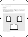
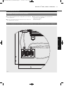
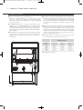
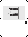
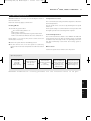
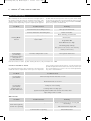
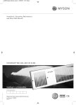
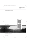
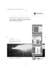
22072 Whispa RCU (US) Manual:Layout 1
10/9/09
12:21
Page 2
Installation, Operating, Maintenance
and After Sales Manual.
WHISPA III ® 5000, 9000 & 12000 RCU
heatingthroughinnovation.
01.06.2009 ISSUE 1
Product Serial Number:
Installation Date:
Part Number: 1371056
Issue 1
Tested to UL & CSA Standards
22072 Whispa RCU (US) Manual:Layout 1
10/9/09
12:21
Page 3
Contents
1.0
General Information
03
2.0
Heating System Design
03
3.0
Selection and Sizing for Heating
03
4.0
Location
03
5.0
Preparation
04
6.0
Electrical Connection
05
7.0
Water Connection
06
8.0
Technical Data
08
9.0
Operating Instructions
09
10.0
Troubleshooting
10
11.0
Maintenance
11
22072 Whispa RCU (US) Manual:Layout 1
10/9/09
12:21
Page 4
WHISPA III ® 5000, 9000 & 12000 RCU
03
G WHISPA III® RCU fan convectors are available in three sizes,
and before proceeding with the installation the heating
system design must be considered and the unit correctly
selected to meet the heat loss requirement of the room.
G WHISPA III® RCU fan convectors are supplied with a fan speed
selector switch mounted on the front of the unit.
G WHISPA III ® RCU fan convectors are supplied with
½" copper tube stubs for both the supply and return.
G A low limit thermostat prevents the fan from operating if the
water temperature in the unit is below 110°F
G WHISPA III® RCU fan convectors are not designed for use with
steam.
G A 24V room thermostat, On – Off or set back type, can be
wired to this unit to give room temperature control.
G A time control can be wired to WHISPA III RCU fan convectors
to provide occasional coil purging flow through the coil if
considered necessary.
G All waterways are of copper. No lead brazing materials are
used to assemble this unit.
4.0
G WHISPA III ® RCU fan convectors are supplied with high
volume purge valve - air vents.
2.0 Heating System Design
The WHISPA III ® RCU can be fitted on a series loop with
mono-flo or venturi Tees, on a two pipe system or as a stand
alone zone.
3. The system water must be above 110°F for fan to switch on,
and best results the mean water temperature should not be
below 140°F.
For optimum fan convector performance the system must be
capable of providing sufficient hot water through the heat
exchanger. This means that:
4. Optimum performance will require effective balancing of the
whole system.
1. Care must be taken in sizing both the pump and piping.
The minimum pipe size from the boiler to the fan convector
must be 1/2" copper tube.
III®
2. Where the WHISPA
RCU is fitted on to a system with other
emitters, mono-flo Tees or diverter Tees should be used to
provide adequate water flow.
5. The WHISPA III ® RCU should not be used to replace a
radiator in an existing system unless an adequate flow of
water can be guaranteed through the unit.
6. The loop must be pumped. WHISPA III® RCU fan convectors
are not suitable for gravity circulation systems.
3.0 Selection and Sizing for Heating
G Heat output performance figures for the three sizes of
WHISPA III ® RCU fan convectors are given in the Technical
Data section of this manual.
G Since WHISPA III® RCU fan convectors are supplied with fan
speed control, it is important to size the unit to match the
calculated heat loss requirements of the room with the unit
operating at the low fan speed (I).
G The higher fan speed can then be used for more rapid
heating from cold in extreme conditions.
G When establishing the temperature difference, i.e. entering
water to room temperature, allowance should be made for
temperature drop in the system. It is the water temperature
at the fan convector that dictates the output.
4.0 Location
G The WHISPA III® RCU fan convector is designed for recessed
wall applications.
G WHISPA III ® RCU fan convectors are designed for normal
2" x 4" stud wall framing, with 5/16" thick cover
extending beyond the wall surface once installed.
2.0
G WHISPA III® RCU fan convectors are designed to be used with
mono-flo Tees from a series loop, on a two pipe system, or as
a stand alone zone.
G WHISPA III® RCU fan convectors are supplied with an integral
combi - zone control and flow control valve, with a factory
fitted insert set to give 1 GPM. The flow rate through the unit
will not exceed this value, however, other inserts of 2 GPM or
3 GPM can be fitted by the installer to give higher flow rates.
3.0
G This MYSON WHISPA III® recessed commercial unit (RCU) is
designed for recessed wall applications where the use of
surface mounted units would not be appropriate. All units
have a one piece low profile front cover.
1.0
1.0 General Information
G The size of the opening required to be cut for installation is
shown in Fig 1.
22072 Whispa RCU (US) Manual:Layout 1
04
10/9/09
12:21
Page 5
WHISPA III ® 5000, 9000 & 12000 RCU
5.0 Preparation
Before proceeding with the installation, unpack the carton
contents and check against the checklist below:
1. WHISPA III® RCU.
2. Instruction manual.
3. Front cover.
4. Screw fixing kit.
G The WHISPA III® RCU fan convector is designed so that the
piping and wiring connections are made within the cabinet of
the unit itself. The installer should inspect the unit and note
that the ½" piping should enter on the lower right corner of
the unit and the 110V AC wiring for the unit enters on the
lower left hand corner of the unit, see Fig 2.
G Prepare the opening in the wall to accept the unit as shown
in Fig. 1. Depending on the wall framing layout, the 9,000 and
12,000 models may require re-framing of the opening to
ensure proper support.
G Do not fit the unit at this stage.
Dimensions of opening to be cut in wall
141/2"
19 5/16"
241/2"
241/2"
9000 RCU
5000 RCU
313/4"
241/2"
12000 RCU
Fig. 1
Note: All models require a depth of at least 3½".
22072 Whispa RCU (US) Manual:Layout 1
10/9/09
12:21
Page 6
WHISPA III ® 5000, 9000 & 12000 RCU
05
6.0 Electrical Connection
WARNING: This appliance must be grounded.
G Make electrical connection to the terminal block:
Black Lead – Hot 110V 60Hz
White lead – Neutral
Green – Ground
G The electrical installation must comply with local or national
wiring regulations.
G A hole is provided at the lower left hand corner of the unit
for a BX or Romex connector.
6.0
5.0
Do not energize the electrical supply until the remaining stages of the installation have been completed.
Tr
Line
(Supply) Ground
Fig. 2
Ac
T
Actu
Neutral
T1
T2 Ground
22072 Whispa RCU (US) Manual:Layout 1
06
10/9/09
12:21
Page 7
WHISPA III ® 5000, 9000 & 12000 RCU
7.0 Water Connection
G This unit is supplied with ½" copper tailpieces.
Bring ½ " copper tubing to the unit and make the
connection . Connect the supply to the left hand isolating
valve. This is necessary to allow proper venting and purging
of the fan convector.
G The WHISPA III ® RCU fan convector is fitted with a flow
regulator set at 1 GPM maximum. If another pre-set
maximum flowrate is required then the insert can be changed
at this stage. Unscrew the insert cap on the flow control valve.
Remove the insert and replace with the alternative. Replace
cap and tighten.
G Many installers are now beginning to use flexible heat tubing
to make these connections. Ensure prior to use that the
tubing selected is appropriate for the water temperature to
be supplied.
G Once the connections to the heating loop are complete, the
unit must be vented using the air purge valve. Fit a length of
hose to the purge valve so that any water from the heating
circuit escaping during the venting process can be directed
to waste, see Fig 3. Open the air purge valve by loosening
the screw.
G Open the left hand valve at the bottom of the unit and purge
the unit for 1-2 minutes. Close the LH valve and then open
the RH valve. Switch on the supply to the unit and energise
the flow control valve by switching on the room thermostat.
Purge the air from the unit, then close the RH valve and switch
off the room thermostat. Close the purge valve, disconnect
the hose and open both valves.
G When the operation of the unit has been tested, align and
secure the front cover (eight screws), see Fig 4.
Dimensions (in)
Model
A
B
C
5000
14 3/16
13 5 /8
10 3/8
7000
19 1/8
17 1 /8
15 1 /16
9000
31 5/8
29 1 /4
27 1 /8
Note: dimensions in inches.
C
B
A
Fig. 3
22072 Whispa RCU (US) Manual:Layout 1
10/9/09
12:21
Page 8
WHISPA III ® 5000, 9000 & 12000 RCU
7.0 Water Connection
07
(continued...)
Front cover
fixing screws
7.0
Fig. 4
22072 Whispa RCU (US) Manual:Layout 1
08
10/9/09
12:21
Page 9
WHISPA III ® 5000, 9000 & 12000 RCU
8.0 Technical Data
Heating Performance Data
Model
Fan Setting
High (II)
5000 RCU
Low (I)
High (II)
Low (I)
High (II)
9000 RCU
Low (I)
High (II)
Low (I)
High (II)
12000 RCU
Low (I)
High (II)
Low (I)
Flowrate
(gpm)
3
1
3
1
3
1
Heat Output (Btu/h)
Entering Water Temperature (°F), Entering Air Temperature (65°F)
110
120
130
140
150
160
170
180
190
200
2040
2516
2997
3480
3967
4457
4949
5443
5939
6437
1749
2096
2437
2773
3104
3432
3756
4078
4397
4713
1795
2214
2637
3063
3491
3922
4355
4790
5226
5664
1539
1844
2144
2440
2732
3020
3306
3589
3869
4147
3759
4629
5504
6385
7271
8160
9053
9949
10848
11750
3266
3916
4556
5185
5807
6422
7031
7634
8233
8827
3308
4073
4844
5619
6398
7181
7967
8755
9546
10340
2874
3446
4009
4563
5110
5652
6187
6718
7245
7767
4369
5437
6524
7623
8739
9866
11003
12149
13307
14472
3019
3733
4454
5180
5911
6649
7389
8136
8887
9640
3845
4785
5740
6709
7690
8682
9682
10692
11709
12734
2657
3284
3918
4558
5202
5851
6504
7160
7819
8482
Maximum inlet water temperature 200°F
Heat outputs tested in accordance with BS 4856 Part 1
Electrical supply: 110V 60Hz
Max working pressure: 145psi
Water connections: 1/2" Sweat
Approximate Hydraulic Resistance through Units
g/min
ft wg
5000
9000
12000
3
4.90
6.89
13.1
1
0.75
1.07
1.4
Fig. 5 Wiring diagram
Weight, Water Content and Motor Power
Model
Motor
Power (W)
Water
Content (fl oz)
Unit Weight
(lbs)
5000
25
5
9.5
9000
40
11.5
14.2
12000
62
18.9
19
22072 Whispa RCU (US) Manual:Layout 1
10/9/09
12:21
Page 10
WHISPA III ® 5000, 9000 & 12000 RCU
09
9.0 Operating Instructions
WHISPA III® RCU fan convectors are controlled by the switch on
the front of the unit.
Temperature Control
Ensure the electricity supply is switched on.
The room thermostat setting should be adjusted to obtain the
desired temperature.
Heating Mode
The fan speed can be set to boost by switching the fan speed
switch to II.
The fan will only operate when
A low speed setting is recommended for normal operation with
the higher speeds for boost heating when required.
•
•
•
•
The
The
The
The
central heating boiler is on
pump is running
system water temperature is greater than 110°F.
room thermostat linked to the unit is switched on.
Ensure boiler is on, and set timer, boiler controls and room
thermostats as necessary.
G Set the fan speed switch to the LOW (I) position.
G The unit will now run on low fan speed. For satisfactory
operation the mean water temperature should not be below
140°F.
Low Limit Operation
The low limit thermostat fitted to the WHISPA III ® RCU will
ensure that the fan stops after the heating system is switched
off and the water flow stops. If left in an operating position the
unit will automatically restart when the heating system is
reheated.
Off Position
Set the fan speed selector switch to the off position.
Operating Sequence
Power On
Timer On
Boiler On
Pump running
Select fan speed
Turn up room
thermostat
Solenoid valve
energises and valve
opens
(1-2 seconds)
Warm water flows
into coil. After 1-2
mins low limit stat
makes as coil
temperature rises
and fan starts.
Unit cycles on room
thermostat through
similar sequence
while heating is on.
9.0
8.0
Maximum differential closing pressure for the solenoid valve is 58 psi.
22072 Whispa RCU (US) Manual:Layout 1
10
10/9/09
12:21
Page 11
WHISPA III ® 5000, 9000 & 12000 RCU
10.0 Troubleshooting
problem with this unit may be the result of system controls being
incorrectly set, and can be solved easily without calling out your
installer or MYSON. Before calling out your installer or MYSON,
please carry out the checklist below.
Once installed, this fan convector becomes an integral part of
the heating system that will also include boiler, pump, other
emitters such as radiators and fan convectors, and a number of
heating controls depending on system complexity. An apparent
Problem
Possible Causes
Remedy
Room thermostat not calling for heat
Turn up room thermostat
Unit not switched on at breaker panel
Switch on breaker
Breaker tripped at panel
Check all wiring, reset breaker
Heating Mode -
Water temperature reaching unit
Check boiler -
No Fan
below 110°F
Programmer ON
Boiler ON and set to high
Circulating pump running
Note: Operation of fan convector can be checked by
switching to summer setting
Heating Mode
poor heating
performance and/or
unit cycles on
low limit thermostat
Low water temperature to unit
Turn up boiler thermostat
Poor water flow
Vent air from heating system
If the fan convector is still faulty after checking the above, call your installer or MYSON.
heat, and the heating system must be correctly designed to
provide adequate flow of hot water to the unit (see section 2). If
the recommendations in section 2 are not followed problems
may arise as detailed below.
Common Installation Faults
For optimum performance, this unit must be correctly sized to
match the heat loss requirements of the space it is required to
Problem
Possible Causes
Poor heating
performance
Unit incorrectly sized for heat loss of room
Boiler thermostat set too low
Lack of flow to fan convector Poor heating
performance
(unit may cycle on
low limit thermostat
Pump set on low setting
Isolating valves not fully open
System incorrectly balanced with unit starved of hot water flow
Pipe sizing to unit too small
Other Faults
Problem
Possible Causes
Remedy
Solenoid valve not energised
Check room thermostat set correctly and
functioning
No flow through unit,
Check transformer output 24V
and fan not operating
Solenoid valve not opening
Check 24V actuator
22072 Whispa RCU (US) Manual:Layout 1
10/9/09
12:21
Page 12
WHISPA III ® 5000, 9000 & 12000 RCU
11
11.0 Maintenance
Before undertaking any maintenance activity isolate the
electrical supply.
Maintenance should be restricted to occasional removal of dust
and lint around the front cover plate.
The unit should be serviced periodically by a competent person.
This should involve internal cleaning of the heat exchanger using
a soft brush or vacuum cleaner, taking care not to damage the
fan or heat exchanger.
Part Number
Quantity
Motor / Fan Assembly WHISPA III® 5000 RCU
7100088
1
Motor / Fan Assembly WHISPA III® 9000 RCU
7100090
1
Motor / Fan Assembly WHISPA III® 12000 RCU
TBA
1
Switch, 3 way
1300025
1
Low Limit Thermostat
1260007
1
Cover plate Whispa III 5000 RCU
TBA
1
Cover plate Whispa III 9000 RCU
TBA
1
Cover plate Whispa III 12000 RCU
TBA
1
24V Actuator
TBA
1
Transformer
TBA
1
11.0
Description
10.0
Spares List
22072 Whispa RCU (US) Manual:Layout 1
10/9/09
12:21
Page 1
MYSON Inc. 948 Hercules Drive, Suite 5, Colchester, Vermont VT05446
T: (802) 654-7500, F: (802) 654 7022, [email protected], www.mysoninc.com
01.06.2009 ISSUE 1
heatingthroughinnovation.