1
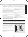
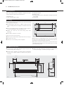
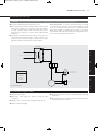
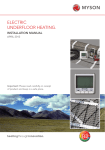
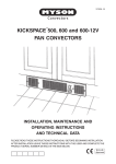
xxxxxx HiLine LV manual_Layout 1 27/06/2011 09:39 Page 2
Installation, Operating, Maintenance
and After Sales Manual.
HI-LINE LV Fan Convector
Model: 7-4
heatingthroughinnovation.
01.02.2010 ISSUE 3
Product Serial Number:
Please leave this manual with the end user.
Part Number: 1370058
Issue 3
xxxxxx HiLine LV manual_Layout 1 27/06/2011 09:39 Page 3
Contents
1.0
General Information
03
2.0
Heating System Design
03
3.0
Unit Selection/Sizing
03
4.0
Location
03
5.0
Preparation
04
6.0
Fixing
04
7.0
Water Connections
04
8.0
Electrical Connection
9.0
Commissioning Procedure
05
10.0
Technical Data
06
11.0
Operating Instructions
06
12.0
Troubleshooting
06
13.0
Maintenance
07
05
xxxxxx HiLine LV manual_Layout 1 27/06/2011 09:39 Page 4
HI-LINE LV Fan Convector
03
l The minimum side clearance is 100mm.
l The HI-LINE LV should only be used on closed circulation, two
pipe, pump assisted central heating systems.
l Before proceeding with the installation, the heating system
design must be considered and the unit correctly sized to
meet the heat loss requirements of the room at normal fan
speed.
l This unit is supplied with a fan speed selector switch giving
two fan speed options and off.
l This unit should not be installed in locations with ceiling
heights greater than 3m.
l This appliance is not intended for use by persons (including
children) with reduced physical, sensory or mental
capabilities, or lack of experience and knowledge, unless they
have been given supervision or instruction concerning use of
the appliance by a person responsible for their safety.
l Children should be supervised to ensure that they do not play
with the appliance.
2.0 Heating System Design
This fan convector must be fitted on a two pipe, pumped
circulation heating system.
For optimum fan convector heating performance the system
must be capable of providing sufficient hot water through the
heat exchanger. This means that:
1. The minimum pipe size from boiler to fan convector must be
at least 15mm.
2. This unit is not suitable for use on microbore pipe-work.
3. Where the unit is fitted on to a system with other emitters a
separate circuit for the fan convector should be considered
to provide adequate water flow.
4. The system water must be above 43°C for heating mode.
5. This unit is NOT suitable for one-pipe systems.
6. Optimum performance will require effective balancing of
the whole system.
7. This unit should NOT be used to replace a radiator in an
existing system unless an adequate flow of water can be
guaranteed.
3.0 Unit Selection/Sizing
Heat output performance is given in the Technical Data section
of this manual. This unit has two fan speed options, however, it
is important to size the unit to match the calculated heat loss
requirements of the room with the unit operating on the low fan
speed. The higher fan speed can then be used for more rapid
heating from cold in extreme conditions.
4.0 Location
l This HI-LINE LV unit may be fitted to any convenient wall at a
height from floor level that suits the application, providing an
unimpeded flow of warm air into the area to be heated.
l The maximum distance from the underside of the unit to floor
level is 2.13m.
OUTSIDE ZONES
l The minimum installation height to the underside of the unit
is 1.8m.
Zone 2
2.25m
Zone 1
3m
l This unit should not be installed in locations with ceiling
heights greater than 3m.
2.0
l This HI-LINE LV unit can be controlled by the addition of a
remote room thermostat. In bathroom installations this must
be connected to the low voltage circuit, and positioned in
accordance with local or national wiring regulations.
3.0
l The minimum installation height to the underside of the unit
is 1.8m.
l This unit is fitted with a 12V transformer that enables the unit
to be fitted in a bathroom. The unit must be positioned in
accordance with local or national wiring regulations.
4.0
l This HI-LINE LV fan convector is designed for wall-mounted
installation with a maximum installation height of 2.13m to
the underside of the unit and a minimum clearance between
the top of the unit and the ceiling of 50mm.
1.0
1.0 General Information
l The unit should be mounted on a flat wall, and stud or
partition walls should be avoided to minimize the possibility
of noise transmission.
Zone 2
Zone 0
l This unit may be fitted in zone 2 or the outside zones of
a bathroom, in accordance with local or national wiring
regulations (see fig 1).
0.6m
m
0.6
Fig. 1
xxxxxx HiLine LV manual_Layout 1 27/06/2011 09:39 Page 5
04
HI-LINE LV Fan Convector
5.0 Preparation
Before proceeding with the installation, unpack the carton
contents and check against the checklist below:
1. HI-LINE LV unit.
2. 15mm isolating valves (1 pair).
3. Instruction manual.
4. Warranty card.
5. Fixing kit (rubber mounts, cable gland and equipotential bond
pipe clamp).
6. Transformer.
6.0 Fixing
l Using the fixing dimensions below (see fig. 2), mark the fixing
hole positions on the wall.
///
//
//
//
///
//
l Remove the backing from the self-adhesive washers and place
on screws with adhesive side towards the point.
//
l Drill and plug the wall for No. 8 x 40mm round head wood
screws ensuring that the wall plugs are suitable for the wall
type.
l Tighten the screws into the wall leaving about 9mm
projecting.
l Press adhesive washers to the wall.
Remove the outer casing as follows:
///
l Remove the 2 screws from the underside of the unit (see fig. 2).
l Lift off the outer case.
l Fit chassis on to mounting screws and tighten.
Fig. 2
Note: Before proceeding with pipe-work connections check that
the unit is level. If the right hand end is lower than the left then
the ability to vent the unit may be restricted.
When water connections and electrical connections have been
completed and the unit has been vented, fit the outer cover and
secure with fixing screws.
7.0 Water Connections
l Connect unit to system flow and return pipes using the two
15mm isolating valves (see fig. 3).
l Open valves fully, check pipe connections for leaks and vent
the heat exchanger - see Commissioning Procedure.
l Ensure system is flushed in accordance with recognized best
practice and a suitable inhibitor is added to the system as
necessary.
/////
/////
//
//
//
//////
//////////
//
///////////////////////////
Fig. 3
///
///
///////
/////////
///
xxxxxx HiLine LV manual_Layout 1 27/06/2011 09:39 Page 6
HI-LINE LV Fan Convector
05
8.0 Electrical Connection
WARNING: The electrical installation must comply with local or national wiring regulations.
l This unit is supplied with a 2m long mains cord.
Room Thermostat - if a remote room thermostat is required
to control the fan convector, remove the link between T1 and
T2 on the terminal block and connect a suitable bimetallic
thermostat, capable of operating at low voltages, across these
two terminals. The thermostat cable entry is through the hole in
the chassis. A cable gland must be used.
l A fused electrical spur with a maximum 3A fuse and a switch
having 3mm separation on all poles must be provided in
an easily accessible position. The fused spur must not be
positioned in a bathroom or other similar high humidity
installations.
l For bathroom installations this unit must be connected to an
equipotential bond using the pipe clamp provided in the
accessories pack. Attach clamp to 15mm flow or return
pipework inside the unit and attach earth conductor.
Transformer
/////////////////
5.0
//
//
///
6.0
//
//
/// // // //
//
Colour Code
/////////
//////////
7.0
//
bl = Blue
r
= Red
y
= Yellow
//
//
8.0
br = Brown
/
/////
/
//////
9.0
Fig. 4 Wiring diagram
9.0 Commissioning Procedure
l Fill and vent the system.
l Open both valves fully and check for leaks at pipe
connections.
l Refit the outer case and secure using the 2 fixing screws.
l Switch on electrical supply.
l Check the operation of the unit by following the operating
instructions.
l When installation and commissioning are complete, hand over
instruction manual to end-user.
xxxxxx HiLine LV manual_Layout 1 27/06/2011 09:39 Page 7
06
HI-LINE LV Fan Convector
10.0 Technical Data
Heating Performance Data
Temperature Difference (°C)
Model
7-4
Heat Output (watts)
Fan Speed
20°
30°
40°
Normal
352
541
734
Boost
645
991
1344
50°
Heat Output (Btu/h)
60°
20°
30°
40°
50°
60°
930
1128
1201
1846
2504
3173
3849
1702
2065
2201
3381
4586
5807
7046
Heat outputs tested in accordance with BS 4856 Part 1.
Flow rate 340 ltr/h (75 gal/h).
Flow Rate Correction Factors:
455 ltr/h (100 gal/h) multiply by 1.06.
227 ltr/h (50 gal/h) multiply by 0.96.
113 ltr/h (25 gal/h) multiply by 0.85.
Noise Levels
Fan Speed
Sound Pressures at 2.5m (dBA)
Normal
16.6
Boost
32.5
Noise levels tested in accordance with EN 23741.
Weight, Water Content and Motor Power
Approximate Hydraulic Resistance through
Fan Convectors
Litres/h
mm wg
kPa
455
1084
9.4
340
798
7.7
227
350
3.5
113
134
1.4
Motor
Power (W)
Water
Content (l)
Unpacked Weight
(kg)
30
0.3
7.4
Test Pressure 20bar (2MPa)
Maximum Working Pressure 10bar (IMPa)
Water connections 15mm
Electrical supply to transformer 230V - 50Hz
11.0 Operating Instructions
The HI-LINE LV is fitted with a fan speed and off selector switch.
Low Limit Operation
Ensure that the electrical supply is switched on.
A low limit thermostat fitted to the HI-LINE LV will ensure that
the fan stops after the heating system is switched off and the
water flow stops. If left in an operating position the unit will
automatically restart when the heating system is reheated.
Heating will only be provided when the central heating boiler is
on, the pump is running and the system water temperature is
greater than 43°C. Ensure boiler is on, and set timer, boiler
controls and room thermostats as necessary.
Turn remote room thermostat (if fitted) to a high setting.
Set fan speed control to position I.
Off Position
Set the fan speed selector switch to the off (O) position.
The unit will now run on low fan speed.
The low speed setting is recommended for normal operation
with the high speed for boost heating (position II) when required.
12.0 Troubleshooting
Once installed this fan convector becomes part of a complete
heating system that will generally include a boiler, pump, other
emitters such as radiators and fan convectors, and a number of
heating controls, dependent on system complexity. An apparent
problem with this unit may be the result of system controls being
incorrectly set and can be solved easily without calling out your
installer or MYSON Service. Before calling your installer or
MYSON Service, please carry out the checks listed opposite.
Note: If you call out MYSON Service to a fault detailed opposite,
or to repair a fault caused by incorrect use, a call out charge will
be made.
xxxxxx HiLine LV manual_Layout 1 27/06/2011 09:39 Page 8
HI-LINE LV Fan Convector
12.0 Troubleshooting
07
(continued...)
Problem
Possible Causes
Remedy
Unit switched off
Turn on
Temperature set point reached
Turn up room thermostat (if fitted)
Unit not switched on at fused spur
Switch on at spur
Heating Mode -
Fuse blown at fused spur
Replace fuse
No Fan
Unit isolating valves shut
Open valves
Water temperature reaching fan
convector below 43°C
Check boiler Programmer ON
Boiler ON and set to high with central
heating pump running
Heating Mode
poor heating
performance and/or
unit cycles on low
limit thermostat
Low water temperature to unit
Turn up boiler thermostat
Poor water flow
Vent air from heating system
If the fan convector is still faulty after checking the above, call your installer or MYSON Service.
Common Installation Faults
For optimum performance, this unit must be correctly sized to
match the heat loss requirements of the space it is required to
heat, and the heating system must be correctly designed to
provide adequate flow of hot water to the unit (refer to section
2). If the recommendations in section 2 are not followed,
problems may arise as detailed below.
Problem
Possible Causes
Poor heating
performance
Unit incorrectly sized for heat loss of room
Boiler thermostat set too low
Lack of flow to fan convector Pump set on low setting
Isolating valves not fully open
System incorrectly balanced with unit starved of hot water flow
10.0
Heating Mode
poor heating
performance and/or
unit cycles on low
limit thermostat
11.0
Pipe sizing to unit too small
13.0 Maintenance
12.0
Maintenance should be restricted to occasional removal of dust
and lint around the unit. The outer surface may be wiped over
with warm water and mild detergent taking care to avoid water
entering the grille areas.
13.0
Before undertaking any maintenance activity isolate the
electrical supply.
xxxxxx HiLine LV manual_Layout 1 27/06/2011 09:39 Page 1
MYSON Eastern Avenue, Team Valley, Gateshead, Tyne & Wear NE11 0PG, UK
T: 0845 402 3434, F: 0191 491 7568, [email protected], www.myson.co.uk
heatingthroughinnovation.
After Sales Service:
Spare parts and technical help on all Convector products are available from MYSON Service.
01.02.2010 ISSUE 3
MYSON Service, Somerden Road, Hull, East Yorkshire HU9 5PE
T: 01482 713927, F: 01482 789056, [email protected]