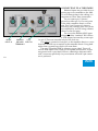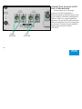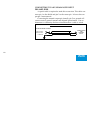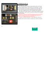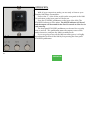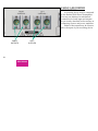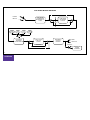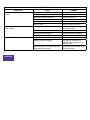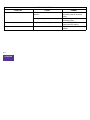
1
Boulder 1008
Phono Preamplifier
Owners Manual
V1.0
10/20/2009
Boulder Amplifiers, Inc.
3235 Prairie Ave.
Boulder, CO 80301
www.boulderamp.com
APPENDIX
RECORDING
EQUALIZATION
OPERATION
CARTRIDGE
SET UP
GETTING
STARTED
TABLE OF CONTENTS
GETTING STARTED
Placement of the 1008 Phono Preamplifier. . . . . . . . . . . . . . . . . . . . . . . . . . . . . . . . . . . . . . 1-1
Connecting to the Mains Outlet . . . . . . . . . . . . . . . . . . . . . . . . . . . . . . . . . . . . . . . . . . . . . . . 1-2
Connecting to a Turntable . . . . . . . . . . . . . . . . . . . . . . . . . . . . . . . . . . . . . . . . . . . . . . . . . . . . 1-3
Phono Cables Diagram. . . . . . . . . . . . . . . . . . . . . . . . . . . . . . . . . . . . . . . . . . . . . . . . . . . . . . . 1-4
Connecting to a Balanced Input Preamplifier. . . . . . . . . . . . . . . . . . . . . . . . . . . . . . . . . . . . 1-5
Connecting to an Unbalanced Input Preamplifier. . . . . . . . . . . . . . . . . . . . . . . . . . . . . . . . 1-6
CARTRIDGE SETUP
Personality Card . . . . . . . . . . . . . . . . . . . . . . . . . . . . . . . . . . . . . . . . . . . . . . . . . . . . . . . . . . . . 2-1
Moving Coil or Moving Magnet . . . . . . . . . . . . . . . . . . . . . . . . . . . . . . . . . . . . . . . . . . . . . . 2-2
Cartridge Loading – Resistive. . . . . . . . . . . . . . . . . . . . . . . . . . . . . . . . . . . . . . . . . . . . . . . . . 2-3
Cartridge Loading – Capacitive . . . . . . . . . . . . . . . . . . . . . . . . . . . . . . . . . . . . . . . . . . . . . . . 2-4
OPERATION
Powering Up. . . . . . . . . . . . . . . . . . . . . . . . . . . . . . . . . . . . . . . . . . . . . . . . . . . . . . . . . . . . . . . . 3-1
Input Selection. . . . . . . . . . . . . . . . . . . . . . . . . . . . . . . . . . . . . . . . . . . . . . . . . . . . . . . . . . . . . . 3-2
Mono. . . . . . . . . . . . . . . . . . . . . . . . . . . . . . . . . . . . . . . . . . . . . . . . . . . . . . . . . . . . . . . . . . . . . . 3-2
Equalization . . . . . . . . . . . . . . . . . . . . . . . . . . . . . . . . . . . . . . . . . . . . . . . . . . . . . . . . . . . . . . . . 3-3
Low Cut Filter . . . . . . . . . . . . . . . . . . . . . . . . . . . . . . . . . . . . . . . . . . . . . . . . . . . . . . . . . . . . . . 3-4
Mute. . . . . . . . . . . . . . . . . . . . . . . . . . . . . . . . . . . . . . . . . . . . . . . . . . . . . . . . . . . . . . . . . . . . . . . 3-5
APPENDIX
RECORDING
EQUALIZATION
OPERATION
CARTRIDGE
SET UP
GETTING
STARTED
EQUALIZATION
Equalization Curves . . . . . . . . . . . . . . . . . . . . . . . . . . . . . . . . . . . . . . . . . . . . . . . . . . . . . . . . . 4-1
RIAA Reproduce Curve. . . . . . . . . . . . . . . . . . . . . . . . . . . . . . . . . . . . . . . . . . . . . . . . . . . . . . 4-2
FFRR Reproduce Curve . . . . . . . . . . . . . . . . . . . . . . . . . . . . . . . . . . . . . . . . . . . . . . . . . . . . . . 4-3
EMI Reproduce Curve . . . . . . . . . . . . . . . . . . . . . . . . . . . . . . . . . . . . . . . . . . . . . . . . . . . . . . . 4-4
Columbia Reproduce Curve . . . . . . . . . . . . . . . . . . . . . . . . . . . . . . . . . . . . . . . . . . . . . . . . . . 4-5
USING A RECORDER
Connections . . . . . . . . . . . . . . . . . . . . . . . . . . . . . . . . . . . . . . . . . . . . . . . . . . . . . . . . . . . . . . . . 5-1
APPENDIX
Block Diagram. . . . . . . . . . . . . . . . . . . . . . . . . . . . . . . . . . . . . . . . . . . . . . . . . . . . . . . . . . . . . . 6-1
Specifications . . . . . . . . . . . . . . . . . . . . . . . . . . . . . . . . . . . . . . . . . . . . . . . . . . . . . . . . . . . . . . . 6-2
Troubleshooting. . . . . . . . . . . . . . . . . . . . . . . . . . . . . . . . . . . . . . . . . . . . . . . . . . . . . . . . . . . . . 6-3
Notes. . . . . . . . . . . . . . . . . . . . . . . . . . . . . . . . . . . . . . . . . . . . . . . . . . . . . . . . . . . . . . . . . . . . . . 6-5
APPENDIX
RECORDING
EQUALIZATION
OPERATION
CARTRIDGE
SET UP
GETTING
STARTED
GETTING STARTED
PLACEMENT OF THE 1008 PHONO PREAMPLIFIER
Your Boulder 1008 Preamplifier is designed to reduce interference
from external magnetic and radio fields (RF). While placement is not
critical, known magnetic fields should be avoided. Power transformers
in other pieces of nearby equipment should be kept away by 1 foot or
more.
Because the preamplifier is heavy, a solid, stable surface should
be used. The 1008 will generate some heat, so it should be allowed to
have good air circulation.
You may want to have some access to the rear panels for cable
changes.
1-1
GETTING
STARTED
r
CONNECTING TO THE MAINS OUTLET
Your 1008 Phono Preamplifier is supplied with a mains cord suitable to the location where it was purchased. Make certain that the “O”
is pushed on the rocker switch before connecting to your mains.
Your 1008 has been configured for the voltage suited to your location. Exact voltage and frequency specifications are located on the rear
panel, right of the AC mains connector.
of
1-2
GETTING
STARTED
CONNECTING TO A TURNTABLE
RIGHT
INPUT #1
1-3
CHASSIS
LEFT
GROUND INPUT #1
TERMINALS
Balanced inputs are provided for connecting up to two turntables to the 1008.
To avoid hum pickup in the cabling, it is
important to follow these instructions.
Do not connect pin 1 (chassis/
ground) to either pin 2 or 3 at any point
in the cable, turntable chassis, or tonearm. Pins 2 and 3 must only connect
directly to the cartridge pins. This can be
accomplished by several wiring schemes
shown on the next page.
Do not use the Boulder ABL2 input
adapter or other “standard” RCA Phono
to XLR adapter because they connect pin
1 to pin 3. These are intended only for line level use.
Use either a connection from pin 1 to the turntable chassis or a wire
from the CHASSIS screw terminal to the turntable chassis. Using both
might form a ground loop which will create hum.
One pair of Boulder PHRCA Adapters are provided. These will
convert 1008 inputs to RCA and give acceptable performance. A separate ground wire is provided. However, obtaining a dedicated cable
with a connector specifically for your tonearm and with 3-pin connectors is preferred.
GETTING
STARTED
PHONO CABLES
1008 PHONO INPUT
CARTRIDGE
2-POS INPUT
3-POS INPUT
1-POS INPUT
TURNTABLE CHASSIS
CHASSIS
1008 PHONO INPUT
CARTRIDGE
2-POS INPUT
3-POS INPUT
N.C.
TURNTABLE CHASSIS
CARTRIDGE
1-POS INPUT
CHASSIS
1008 PHONO INPUT
2-POS INPUT
3-POS INPUT
1-POS INPUT
TURNTABLE CHASSIS
1-4
CHASSIS
 GETTING
STARTED
CONNECTING TO A BALANCED
INPUT PREAMPLIFIER
For maximum sonic advantage,
connect your 1008 Preamplifier’s
balanced outputs to balanced inputs such
as provided on all Boulder Preamplifiers.
With the 1008’s low output impedance,
distances of more than 50 meters between
Phono Preamplifier and Line Preamplifier
are practical. Connect each preamplifiers
input to the connectors labeled
“OUTPUT.”
RIGHT
OUTPUTS
1-5
LEFT
OUTPUTS
GETTING
STARTED
CONNECTING TO AN UNBALANCED INPUT
PREAMPLIFIER
A special cable is required to make this connection. This cable connects pin 1 to the shield and pin 2 to the center pin. It leaves the output pin 3 unconnected.
Connecting the unused output pin (usually pin 3) to ground will
cause excessive ground currents and degrade performance. Use an
ohmmeter or continuity checker to determine how a cable is wired.
UNBALANCED OUTPUT CABLE
2008 BALANCED OUTPUT
2-POS OUTPUT
3-NEG OUTPUT
UNBALANCED
LINE
PREAMP
INPUT
1-GROUND
1-6
GETTING
STARTED
CARTRIDGE SET UP
PERSONALITY CARD
Each 1008 input has two slots for personality cards, one for left,
and one for right channels. The cards serve two functions– a switch
to set the electronics for the type of cartridge used at that input, and
places to solder the custom load termination resistor and capacitor.
The 1008 is shipped with all 4 cards installed in the rear panel.
The cards are set to MC, and have a load resistor installed to set the
input impedance to 100Ω. These are the most commonly used settings
for a MC cartridge.
WARNING: Press the STANDBY pushbutton until the STANDBY
indicator is off before removing or inserting the personality card.
Failure to do so might result in very loud clicks.
To remove, pull the card firmly. To insert, push the card until it
completely seats into the connector and the face is flush to the panel.
2-1
CARTRIDGE
SET UP
MOVING COIL OR MOVING MAGNET SELECTION
Set the switch to either Moving Coil (MC) or Moving Magnet (MM)
depending on your type of cartridge.
In the MC position, the maximum input resistance is 1,000Ω without additional components installed on the card. All four of the cards
are shipped with a resistor to bring the impedance down to 100Ω,
which is recommended for MC. Also in the MC position, an additional
low noise, 26 dB gain stage is inserted at the input.
In the MM position, the maximum input resistance is 47K Ω without additional components installed on the card. This is the impedance
recommended for MM.
2-2
CARTRIDGE
SET UP
CARTRIDGE LOADING – RESISTIVE
R1
2-3
For MC cartridges, the maximum resistive load is 1,000Ω. This is
the value when there is no resistor added to the Personality Card. This
value may be lowered by adding a resistor (as shown) at R1 whose
value is calculated by the following:
R1 = 1/(1/RDESIRED – .001)
Some typical values are:
Desired R (Ω)
R1 (Ω)
50
52.3
100
110
200
249
500
1,000
For MM cartridges, the maximum resistive load is 47kΩ. This is
the value when there is no resistor added to the Personality Card. This
value may be lowered by adding a resistor (as shown) at R1 whose
value is calculated by the following:
R1 = 1/(1/RDESIRED – .0000213)
Some typical values are:
Desired R (Ω)
R1 (Ω)
1,000
1,020
5,000
5,620
10,000
12,700
20,000
34,800
CARTRIDGE
SET UP
CARTRIDGE LOADING – CAPACITIVE
CONNECT CAPACITOR
FROM ONE LEFT HOLE
TO ONE RIGHT HOLE
2-4
The 1008 Phono Preamplifier inputs have only “parasitic” capacitance of less than 50 pF directly across the cartridge inputs. If desired,
additional capacitance can be added on the personality card at C1. The
capacitor chosen should be 50 pF less than the desired value.
Solder holes are provided for two different size capacitors. There
are two pairs of holes as shown, two at left and two at right. Each pair
is connected together. The capacitor need be soldered to only one of
the left and one of the right holes.
All solder holes have grommets to reinforce the PC board when
parts are installed and removed. Do not remove these grommets.
BOULDER SUGGESTS: While there are some cartridge manufacturers who recommend using capacitive loading, we suggest that you
do not. Adding more capacitance only lowers the resonant frequency of
the capacitor and the cartridge winding inductance, particularly with
MM cartridges. The resonance peak is still just as high and destructive
to the sound.
Instead, try a lower resistor value; the lower the value, the “heavier” the load and the lower the resonance peak (not frequency) thus giving better dampening to the cartridge.
With low level MC cartridges, there is virtually no effect of capacitive loading because the cartridge output impedance is inherently very
low.
CARTRIDGE
SET UP
OPERATION
POWERING UP
With all your connections made, you are ready to listen to your
Boulder 1008 Phono Preamplifier.
Push on the “I” of the rocker switch on the rear panel of the 1008.
No indication on the front panel will be shown.
Press the STANDBY pushbutton on the front of the 1008. The
STANDBY indicator will be amber. The MUTE indicator will be red
and the output will be muted for the first 35 seconds to allow for circuit warm up.
The front panel STANDBY pushbutton can be used for everyday
turn on and off. This pushbutton mutes the outputs, turns off the
audio electronics, and puts the 1008 in standby mode.
If you are going to turn off the 1008 rear main power, it is highly
recommended to turn off the 1008 by first pressing the front panel
STANDBY pushbutton.
3-1
OPERATION
INPUT SELECTION
The Boulder 1008 Phono Preamplifier provides inputs for 2 cartridges. These can be from one or more turntables. Only one of these
inputs can be used at a time.
Select an input by pressing one of the pushbuttons labeled “INPUT
1” and “INPUT 2”. The 1008 will immediately mute the outputs and
the MUTE indicator will be red for 3 seconds. After that time, the output will be unmuted and the MUTE indicator will be off.
Anytime a different input is selected, the 1008 will similarly mute
for 3 seconds.
It is not recommended to select an input that has no cartridge connected. Make connections to an input first and then select the input. If
it is necessary to have all inputs disconnected, then mute the preamplifier temporarily.
MONO
3-2
To enhance monaural recordings played with a stereo cartridge, it
is often desired to mix the left and right channels together to form a
true monaural signal. In the 1008 it is possible to do this by turning on
MONO mode.
Pressing the MONO pushbutton will place the 1008 into monaural
mode and the MONO indicator will be red.
To return to normal stereo operation, again press the MONO pushbutton. The MONO indicator will be off.
OPERATION
EQUALIZATION
The Boulder 1008 Phono Preamplifier provides the standard RIAA
record equalization curve, along with the EMI, Columbia, and FFRR
curves. See the Equalization section for more details.
Select the RIAA equalization curve by pressing the pushbutton
labeled RIAA. All three remaining curves may be selected by using
the pushbutton labeled ALT EQ. Various alternate EQs are selected by
repeatedly pushing “ALT EQ” until the desired LED is red. The 1008
will immediately mute the outputs and the MUTE light will be red for
3 seconds. After that time, the output will be unmuted and the MUTE
indicator will be off.
Anytime a different equalization is selected, the 1008 will similarly
mute for 3 seconds.
If the chosen equalization curve is RIAA, the RIAA indicator will
be amber. If the chosen equalization curve is any other EQ curve, its
respective indicator will be red.
3-3
OPERATION
LOW CUT FILTER
The Boulder 1008 Phono Preamplifier uses a 3 pole (18 dB/octave)
low cut filter which is -3db at 10 Hz.
Because this filter is fairly steep, its effect is virtually negligible in
the audio band. It is recommended that it be kept turned on in order to
avoid excessive woofer travel caused by imperfect records.
Select the low cut filter by pressing the pushbutton labeled LOW
CUT. The indicator will then be amber.
To completely turn off the filter, again press the pushbutton labeled
LOW CUT. The low cut filter will be switched out and the indicator
will turn off.
WARNING: Due to some low frequency content of many recordings, care should be taken in regard to volume level when turning the
low cut filter on or off as there may be some audible transient (click).
This effect is normal.
3-4
OPERATION
MUTE
The Boulder 1008 Phono Preamplifier provides an output mute feature which is turned on by two different methods.
First, the outputs are muted for 35 seconds when the 1008 is first
turned on. The 1008 is also muted for 3 seconds when an input or
equalization pushbutton is pressed. The MUTE indicator will be red.
Second, the outputs may be muted at any time for your convenience by simply pressing the MUTE pushbutton. the MUTE indicator
will be red.
To unmute, press the MUTE pushbutton again. The MUTE indicator will turn off and the outputs will unmute unless there has been a
cycle initiated by the first method above. In that case the outputs will
remain muted and the MUTE indicator red until that timeout has finished.
When the STANDBY pushbutton is used to turn off the 1008 or
there is no power, the outputs will be muted.
3-5
OPERATION
EQUALIZATION
EQUALIZATION CURVES
The Boulder 1008 Phono Preamplifier uses one of four equalization
curves selected by the front panel pushbuttons labeled RIAA and ALT
EQ. The 1008 is shipped with four standard EQ options: RIAA, FFRR,
EMI, and Colombia.
The following pages show the four equalization curves. All graphs
are referenced to 0 dB at 1 kHz.
4-1
EQUALIZATION
RIAA REPRODUCE EQUALIZATION
REF 0 DB AT 1 KHZ
4-2
EQUALIZATION
FFRR REPRODUCE EQUALIZATION
REF 0 DB AT 1 KHZ
4-3
EQUALIZATION
EMI REPRODUCE EQUALIZATION
REF 0 DB AT 1 KHZ
4-4
EQUALIZATION
COLUMBIA REPRODUCE EQUALIZATION
REF 0 DB AT 1 KHZ
4-5
EQUALIZATION
USING A RECORDER
CONNECTIONS
A recording device may be connected
to the Boulder 1008 Phono Preamplifier.
You may use balanced or unbalanced
connections for both input and outputs
as previously described in the sections on
connecting sources and power amplifiers.
Either of the outputs may be connected to the input of your recording device.
RIGHT
OUTPUTS
5-1
RECORDING
LEFT
OUTPUTS
1008 AUDIO BLOCK DIAGRAM
1
PHONO
INPUTS
CARTRIDGE
LOADING ON
PERSONALITY
CARD
2
1K
LOW NOISE
26 dB GAIN
FOR MC
47K
MM BYPASS
RIAA
EMI
COL
PLAYBACK
GAIN AND
EQUALIZATION
FFRR
10 HZ / 3-POLE
LOW CUT
FILTER
BYPASS
BALANCED
OUTPUT
BUFFER
MAIN
OUTPUTS
STEREO
MONO
6-1
APPENDIX
FROM / TO OTHER
CHANNEL
BOULDER 1008 PHONO PREAMPLIFIER SPECIFICATIONS
Inputs
2 Balanced, Converts to Unbalanced
Input Impedance, Maximum
MC: 1000 Ω; MM: 47kΩ
1kHz Gain, RIAA
MC: 70, MM: 44
Noise (EIN), MC
98 nanovolts Flat, 20 Hz to 20kHz
Outputs
2 Balanced, use as Main or Record
Maximum Output Level
16 Vrms
Distortion, THD
0.01%
Frequency Response, 20 Hz to 20 kHz
RIAA: ±0.10 dB
Crosstalk, L to R or R to L
>100 dB or better 20 Hz to 20kHz
Output Impedance
100Ω Balanced
Preamp Size, W X H X D
18.0 x 5.0 x 15.85 inches
Weight
32, Shipping: 41 pounds
Power
50-60 Hz, 30W, Voltage by country
6-2
APPENDIX
SYMPTOM
No power indication
on 1008
TROUBLESHOOTING
CAUSE
Power switch is not in ON position
Turn on power switch
Home circuit breaker is tripped
Reset circuit breaker
1008 is not plugged in
Low AC line voltage
Power supply fuse blown
Amber power indication on 1008, but no
sound is heard
Defective 1008
1008 is muted, MUTE indication is Amber
No signal from turntable
No signal out to preamplifier
Hum through loudspeakers
6-3
APPENDIX
REMEDY
1008 is faulty
Connect to an AC outlet
Have AC line checked
Replace fuse on rear panel
Return to dealer for service
Press MUTE pushbutton to turn
mute indicator OFF
Check turntable connections
Check connections to preamp
Return to dealer for service
No ground connection
Check or install ground wire
1008 or turntable is too close to another
components power supply
Move 1008 and/or turntable away
from power supply
Duplicate ground connection
Use only one ground wire to
turntable or use the ground in a
balanced cable
SYMPTOM
One channel is louder than the other
TROUBLESHOOTING
CAUSE
MM/MC switch is not set the same on both Set MM/MC switches on
channels
personality cards to the same
setting
Cartridge loading is not equal
Tonality or frequency response is incorrect Wrong equalization setting is selected
Will not come out of Mute
6-4
APPENDIX
REMEDY
1008 has not been stabilized after turn-on
Check cartridge loads on
personality cards
Press ALTERNATE EQ button to
select proper EQ setting
Wait 35 seconds for 1008 to
stabilize
NOTES
Serial Number ________
6-5
APPENDIX