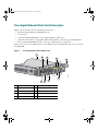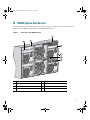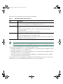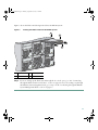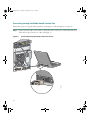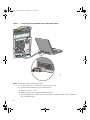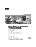
1
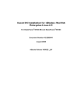
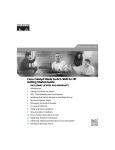
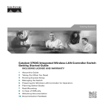
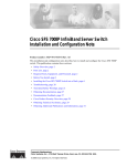
3040GSG.fm Page 1 Monday, September 18, 2006 9:45 AM
Getting Started Guide
Cisco Catalyst Blade Switch 3040 for FSC
Getting Started Guide
INCLUDING LICENSE AND WARRANTY
1
Introduction
2
Taking Out What You Need
3
BX600 System Architecture
4
Preparing to Install the Blade Switch in the BX600 System
5
Managing the Blade Switch
6
In Case of Difficulty
7
Obtaining Documentation
8
Documentation Feedback
9
Cisco Product Security Overview
10 Obtaining Technical Assistance
11 Obtaining Additional Publications and Information
12 Hardware Warranty Terms
3040GSG.fm Page 2 Monday, September 18, 2006 9:45 AM
1 Introduction
This guide provides instructions on how to install your Cisco Catalyst Blade Switch 3040 for
FSC—referred to as the blade switch—in the Fujitsu Siemens PRIMERGY BX600 S2 system and to set
up and configure it. The PRIMERGY BX600 S2—referred to as the BX600 system—supports up to
four Ethernet blade switches in its blade bays.
This guide also covers management options and troubleshooting help for the blade switch.
For details on the numbers, types, and the location of the BX600 system slots, for additional
information on the BX600 system, and for detailed port mapping information, see the BX600 setup
and installation guide at http://manuals.fujitsu-siemens.com/primergyservers.html.
For additional installation and configuration information about the blade switch, see the Cisco
Catalyst Blade Switch 3040 for FSC documentation on Cisco.com. For system requirements, important
notes, limitations, open and resolved caveats, and last-minute documentation updates, see the release
notes, also on Cisco.com.
When using the online publications, refer to the documents that match the Cisco IOS software version
that is running on the blade switch. See the “Obtaining Documentation” section on page 1-24 for more
information about the related publications.
For translations of the warnings that appear in this publication and all safety and handling warnings
for this product, see the Regulatory Compliance and Safety Information for the Cisco Catalyst Blade
Switch 3040 for FSC that accompanies this guide.
Before proceeding, read the release notes for the BX600 system. The release notes are available on the
FSC support website at http://support.fujitsu-siemens.com/com/support/index.html.
2 Taking Out What You Need
These items ship with your blade switch:
• Console cable
• Cisco Catalyst Blade Switch 3040 for FSC Getting Started Guide (this book)
• Regulatory Compliance and Safety Information for the Cisco Catalyst Blade Switch 3040 for FSC
• Registration card
Follow these steps:
1. Unpack and remove the blade switch and the accessory kit from the shipping box.
2. Return the packing material to the shipping container, and save it for future use.
If you ordered the blade switches with the BX600 system, they are already installed. The unpacking
procedure only applies if a blade switch is ordered separately. See the BX600 system documentation
for the unpacking procedure for the BX600 system equipment.
2
3040GSG.fm Page 3 Monday, September 18, 2006 9:45 AM
Cisco Gigabit Ethernet Blade Switch Description
Figure 1 shows the blade switch, which has these features:
• 10 internal Gigabit Ethernet 1000BASE-X ports
• 1 console port
• 2 external 10/100/1000BASE-T copper Gigabit Ethernet uplink ports
• 4 external small form-factor pluggable (SFP) module uplink ports that support 1000BASE-SX
fiber and 10/100/1000BASE-T copper (only Cisco SFP modules are supported)
Each port has an associated LED. The associated BX600 system management blade controls a System
Status/ID LED.
Figure 1
The Catalyst Blade Switch 3040 for FSC
1
5
CON
12x
11x
Console
ID
7
12x
11x
13x
13x
14x
14x
9
15x
15x
8
3
4
16x
16x
190180
2
6
1
Blade switch
6
Gigabit Ethernet port LEDs
2
Console port
7
SFP module ports
3
Console port LED
8
SFP module port LEDs
4
System Status/ID LED
9
Release latch
5
Gigabit Ethernet ports
3
3040GSG.fm Page 4 Monday, September 18, 2006 9:45 AM
The blade switch is powered from the BX600 S2 system backplane, and temperature management is
provided by the BX600 S2 system. The blade switch has no fan.
To set up the switch, you need a PC and an Ethernet (Category 5) straight-through cable (as shown)
or a console cable (ships with the product).
4
3040GSG.fm Page 5 Monday, September 18, 2006 9:45 AM
3 BX600 System Architecture
The four BX600 system I/O blade slots are on the rear panel (see Figure 2). You can insert blade
switches into the NET1, NET2, NET3, and NET4 I/O blade slots.
Figure 2
Rear View of the BX600 System
1
4
2
Console
12x
11x
13x
11x
12x
13x
14x
14x
15x
15x
16x
16x
3
5
6
190181
7
1
NET1 slot (with blade switch installed) 5
Rear panel of the BX600 system
2
NET2 slot
6
BX600 system management blade
3
NET3 slot
7
Advanced KVM1 blade
4
NET4 slot
1. KVM = Keyboard, video, mouse connection
5
3040GSG.fm Page 6 Monday, September 18, 2006 9:45 AM
Figure 3 shows the BX600 system management blade on the left and an optional advanced KVM blade
on the right.
Figure 3
BX600 System Management and Advanced KVM Blades
2
3
5
4
6
7
190182
1
1
RS-232 serial port
5
Failure indicator LED
2
Ethernet port
6
Advanced KVM blade Ethernet port
7
KVM connector
1
3
I2C connector
4
Green master indicator LED
2
1. A proprietary Intelligent Platform Management Interface (IPMI) connector for Fujitsu
Siemens Computers service applications
2. The KVM connector uses a special cable to connect a VGA monitor, a PS2 keyboard,
and a PS2 mouse.
6
3040GSG.fm Page 7 Monday, September 18, 2006 9:45 AM
Table 1 describes the BX600 system management blade LEDs:
Table 1
Management Blade LED Descriptions
LED
Description
Ethernet port
Green: On shows link is up; blinking shows power is on.
Amber: On shows LAN is active; blinking shows power is on.
Master (green)
On: The management blade is the master, responsible for managing the entire
system.
Off: The management blade is a slave—a standby or backup of the master
management blade.
Blinking: The management blade is in special mode.
Failure (amber)
On: If only one management blade is installed, it has failed.
Off: This management blade is operating normally.
Blinking: The management blade is running in power-on mode, that is, generating
a heartbeat for the master/slave selection.
Note
For more information about the master and failure management blade LEDs or the advanced
KVM management blade, see the PRIMERGY BX600 Basic Unit Operating Manual.
Consider these requirements before you install your blade switch:
• The NET1 and NET2 slots are a pair. If the NET2 slot is used, the I/O blade in the NET2 slot must
be the same type as the one in the NET1 slot.
• The NET3 and NET4 slots are a pair. If the NET4 slot is used, the I/O blade in the NET4 slot must
be the same type as the one in the NET3 slot.
• If the blade switch is installed in the NET3 and NET4 slots, an Ethernet I/O module (daughter
card) must be installed on the BX600 server.
For information about requirements for installing blades in the BX600 system or the components of
the BX600 system, see the PRIMERGY BX600 Basic Unit Operating Manual.
7
3040GSG.fm Page 8 Monday, September 18, 2006 9:45 AM
4 Preparing to Install the Blade Switch in the BX600 System
Before you install the blade switch in the BX600 system, review the safety and compliance
information:
• Review and become familiar with the safety guidelines in the Regulatory Compliance and Safety
Information for the Cisco Catalyst Blade Switch 3040 for FSC that accompanies this guide.
• Review and become familiar with the BX600 system safety guidelines in the BX600 system
documentation.
• Review and become familiar with any temperature, power, and grounding requirements specified
in the BX600 system documentation.
Warning
Only trained and qualified personnel should be allowed to install, replace, or service
this equipment. Statement 1030
Caution
To prevent electrostatic-discharge (ESD) damage when installing blade switches, follow
your normal board and component handling procedures.
Note
When you initially configure a blade switch, it should be in the same state as when it was
shipped, that is, unconfigured and with no assigned default username and password.
When you install a blade switch, you do not need to power down the BX600 system.
Overview of Steps for Installing and Configuring the Blade Switch
You can install and configure the blade switch by using either of two methods. In each, you start a
terminal-emulation program on a PC. The terminal-emulation software—a PC application such as
Hyperterminal or ProcommPlus—makes communication between the blade switch and your PC or
terminal possible. The PC communicates with the blade switch either through its console port or
through the console port of BX600 system management blade.
• To set up the blade switch through its console port, start with the next section, “Installing the
Blade Switch in the BX600 System.”
• To set up the blade switch through the BX600 system management blade, first connect it to a PC
to run the terminal emulation program and to interact with the console menu. Do this before you
install the blade switch into the BX600 system. Start with the “Connecting through the BX600
System Management Blade” section on page 13.
8
3040GSG.fm Page 9 Monday, September 18, 2006 9:45 AM
Installing the Blade Switch in the BX600 System
Follow these steps to install the blade switch in the BX600 system:
Step 1
Obtain and make note of this information from your system administrator before you begin
the blade switch installation:
– Switch IP address
– Subnet mask (IP netmask)
– Default gateway (router)
– Enable secret password (encrypted)
– Enable password (not encrypted)
– Telnet password
– SNMP community strings (optional)
Step 2
Touch the blade switch static-protective package to unpainted metal on the BX600 system for
at least 2 seconds.
Step 3
Remove any dummy blade from the slot.
Caution
Keep dummy blades for future use. If you remove the blade switch and do not replace it
with another one, you must reinstall a dummy blade in that slot.
Step 4
Remove the blade switch from its static-protective package.
Step 5
Select the I/O slot in which to install the blade switch. Follow the installation requirements
listed in the “BX600 System Architecture” section on page 5.
9
3040GSG.fm Page 10 Monday, September 18, 2006 9:45 AM
Step 6
Figure 4
Ensure that the release latch on the blade switch is in the open position. (See Figure 4.)
Open the Blade Switch Release Latch
1
CON
1
ID
11x
12x
13x
13x
14x
14x
15x
15x
16x
16x
190183
12x
11x
Console
Release latch in open position
Step 7
Slide the blade switch into the slot until it stops.
Step 8
Push the release latch on the front of the blade switch toward the right and into the closed
position.
10
3040GSG.fm Page 11 Monday, September 18, 2006 9:45 AM
Figure 5 shows the blade switch being inserted into the BX600 system.
Figure 5
Inserting the Blade Switch into the BX600 System
2
1
CON
12x
11x
Console
ID
13x
11x
12x
13x
14x
14x
15x
15x
16x
16x
190184
3
1
Blade switch
2
Release latch
Step 9
3
BX600 system
If you are setting up the blade switch through the its console port, go to the “Connecting
through the Blade Switch Console Port” section on page 12. If you are setting it up through
the BX600 system management blade, go to Step 6 in the “Connecting through the BX600
System Management Blade” section on page 13.
11
3040GSG.fm Page 12 Monday, September 18, 2006 9:45 AM
Connecting through the Blade Switch Console Port
Follow these steps to set up the blade switch by connecting it to a PC through its console port:
Connect one end of the console cable to the blade switch console port. Connect the other end
of the cable to the serial port of a PC. (See Figure 6.)
Step 1
Figure 6
Console
Connecting through the Blade Switch Console Port
12x
11x
12x
13x
14x
14x
15x
15x
16x
16x
190185
11x
13x
12
3040GSG.fm Page 13 Monday, September 18, 2006 9:45 AM
Step 2
Start the terminal emulation session so you can see the output display from the power-on
self-test (POST).
Step 3
On the PC terminal emulation program:
a. Set the data format to 8 data bits, 1 stop bit, and no parity.
b. Set the terminal emulation speed to 9600 baud.
c. Set the flow control to None.
Step 4
Go to the “Waiting for POST to Complete” section on page 16 to finish configuring the blade
switch.
Connecting through the BX600 System Management Blade
Follow these steps to set up the blade switch by connecting to a PC through the BX600 system
management blade console port:
Step 1
Connect one end of a DB9 null-modem or a crossover cable to the RS-232 console serial port
of the associated management blade. Connect the other end of the cable to the RS-232 console
serial port of the PC. (See Figure 7.)
13
3040GSG.fm Page 14 Monday, September 18, 2006 9:45 AM
Figure 7
Console
Connecting through the BX600 System Management Blade
12x
11x
12x
13x
14x
14x
15x
15x
16x
16x
190186
11x
13x
Step 2
On the PC terminal emulation program:
a. Set the data format to 8 data bits, 1 stop bit, and no parity.
b. Set the terminal emulation speed to 115200 baud.
c. Set Flow Control to none.
d. Under Properties, select VT100 for Emulation mode.
e. Select Terminal keys for Function, Arrow, and Ctrl keys. Make sure that you select Terminal
keys not Windows keys.
14
3040GSG.fm Page 15 Monday, September 18, 2006 9:45 AM
Step 3
On the console monitor, the management blade application displays a login screen. Log in by
using these defaults:
username root
password root
The management blade Console Main menu appears.
Note
Step 4
If the BX600 system is already configured, obtain the management blade username
and password from the system administrator. If you use root for the username and
password, you must change them later. See the BX600 system documentation for
more information.
To power on the BX600 system, use these menu choices in the Console Main menu:
a. Enter 1 (Management Agent). The Management Agent menu appears.
b. Enter 3 (System Information). The System Information menu appears.
c. Enter 2 (Power Supply). The Power Supply menu appears.
d. Enter 1 (Power Control). The Power Control menu appears.
e. Enter 2 to power on the BX600 system.
f. Enter 0 at each menu to return to the main menu.
Note
The management blade console menu uses a hot key to return to a previous menu. The default
is set to Ctrl–Q. For some terminal emulation programs, Ctrl–Q might not work. You can
reset the hot key in the Console Redirection Table menu. Choose a character from A-Z,
excluding M. The hot key to exit console redirection and return to the previous mode is then
Ctrl + the character you have set. For more information, see the BX600 system
documentation.
Step 5
Install the blade switch by following the instructions in the “Installing the Blade Switch in the
BX600 System” section on page 9, and then return to this section.
Step 6
After you have installed the blade switch in the BX600 system, wait for the blade switch port
11x LED to blink green before you continue.
Step 7
Enter 3 (Console Redirection) on the main menu to open the Console Redirection Table menu.
Step 8
Enter 2 (Console Redirect Switch Blade) in the Console Redirection Table menu to redirect
the console to the blade switch. The Console Redirection Switch Blade menu appears.
Step 9
Enter 1 if you are configuring the blade switch in the NET1 slot, 2 if you are configuring the
blade switch in the NET2 slot, and so on.
15
3040GSG.fm Page 16 Monday, September 18, 2006 9:45 AM
Step 10 Go to “Waiting for POST to Complete” section on page 16 to finish configuring the blade
switch.
If the blade switch is already installed and powered up when you use the BX600 system management
blade console menu, you must reboot the switch to display the system configuration dialog:
1. Enter enable at the user EXEC ( Switch>) prompt, then enter reload at the privileged EXEC mode
(Switch#) prompt.
2. Follow the instructions in the next section, “Waiting for POST to Complete.”
Waiting for POST to Complete
Follow these steps:
Step 1
Wait several minutes for the blade switch to complete the POST.
Step 2
The POST is complete when the System Status/ID LED is off and the Console LED is solid
green or amber.
If the blade switch fails POST because of a misconfiguration or error, the System Status/ID
LED blinks green and the Console LED is off.
Note
POST errors are usually fatal. Call Cisco Customer Support immediately if your blade
switch fails POST.
Step 3
Wait for the blade switch to complete flash initialization. When you see the prompt Press
Return to Get Started!, wait for any interface status information output to finish its
appearance, then press Return or Enter.
Step 4
Make sure that the System Status/ID LED is off and that the Console LED is green or amber.
The blade switch is now operating properly.
Step 5
See the “Completing the Initial Configuration” section on page 17 for instructions on setting
up and initially configuring the blade switch.
16
3040GSG.fm Page 17 Monday, September 18, 2006 9:45 AM
Completing the Initial Configuration
Follow these steps to complete the setup program and to create an initial configuration.
Note
For information about how to automatically configure the blade switch, see the “Assigning
the Switch IP Address and Default Gateway” chapter in the blade switch configuration guide.
Step 1
After you have pressed Enter or Return after the prompt to start the system configuration
dialog, enter yes at these prompts:
Would you like to terminate autoinstall? [yes]: yes
--- System Configuration Dialog --Continue with configuration dialog? [yes/no]: yes
At any point you may enter a question mark '?' for help.
Use ctrl-c to abort configuration dialog at any prompt.
Default settings are in square brackets '[]'.
Basic management setup configures only enough connectivity
for management of the system, extended setup will ask you
to configure each interface on the system
Would you like to enter basic management setup? [yes/no]: yes
Step 2
Enter a hostname for the blade switch after the prompt, and press Return.
The hostname is limited to 20 characters. Do not use -n, where n is a number, as the last
character in a host name for any blade switch.
Step 3
Enter an enable secret password, and press Return.
The password can be from 1 to 25 alphanumeric characters, can start with a number, is case
sensitive, allows spaces, but ignores leading spaces. The secret password is encrypted, and the
enable password is in plain text.
Step 4
Enter an enable password, and press Return.
Step 5
Enter a virtual terminal (Telnet) password, and press Return.
The password can be from 1 to 25 alphanumeric characters, is case sensitive, allows spaces,
but ignores leading spaces.
17
3040GSG.fm Page 18 Monday, September 18, 2006 9:45 AM
Step 6
(Optional) Configure Simple Network Management Protocol (SNMP) by responding to
the prompts.
To configure SNMP later, press Return (which applies the default of no). If you accept the
default, you can configure SNMP later through the CLI.
Configure SNMP Network Management? [no]:
To configure SNMP now, enter yes.
Configure SNMP Network Management? [no]: yes
Community string [public]: public
The Current interface summary displays.
Step 7
Enter vlan1 for the interface name at this prompt:
Enter interface name used to connect to the management network from the above
interface summary.
Step 8
To configure the interface, enter Yes after the prompt, and then enter the blade switch
IP address and subnet mask. Press Return.
The IP address and subnet mask shown here are examples:
Configuring interface Vlan1:
Configure IP on this interface? [yes]: Yes
IP address for this interface [10.0.0.1]: 10.0.0.1
Subnet mask for this interface [255.255.255.0] : 255.255.255.0
Class A network is 10.0.0.1, 21 subnet bits; mask is /21
Step 9
Enter no when the prompt asks you if you would like to enable the blade switch as a cluster
command switch. This is a standalone blade switch.
Would you like to enable as a cluster command switch? [yes/no]: no
Note
Clustering is not supported on the Cisco Catalyst Blade Switch 3040 for FSC.
You have now completed the initial configuration. An example of the output is shown here:
The following configuration command script was created:
hostname switch1
enable secret 5 $1$cagJ$e4LP91PNazfdADoNAZm6y0
enable password enable_password
line vty 0 15
password terminal-password
snmp-server community public
!
!
interface Vlan1
18
3040GSG.fm Page 19 Monday, September 18, 2006 9:45 AM
no shutdown
ip address 10.0.0.1 255.255.255.0
!
interface GigabitEthernet0/1
!
interface GigabitEthernet0/2
. . . (output truncated)
interface GigabitEthernet0/16
!
end
Step 10 These choices appear. Enter 2, and then press Return.
[0] Go to the IOS command prompt without saving this config.
[1] Return back to the setup without saving this config.
[2] Save this configuration to nvram and exit.
If you want to save the configuration and use it the next time the switch reboots,
save it in NVRAM by selecting option 2.
Enter your selection [2]:2
Make your selection, and press Return.
Step 11 If you plan to set up more than one blade switch, enter Ctrl-Q to return to the Console
Redirect Switch Blade menu, and choose the next blade switch. When you have set up all of
the blade switches, enter 0 on the Console Redirect Switch Blade menu to return to the
management blade Console Main menu. This re-enables the blade switch console port.
Step 12 Disconnect the BX600 system serial port or the blade switch console port from the PC. See the
“Managing the Blade Switch” section on page 20 for information about configuring and
managing the blade switch.
If you need to rerun the system configuration dialog, see the “Resetting the Switch Configuration”
section on page 24.
19
3040GSG.fm Page 20 Monday, September 18, 2006 9:45 AM
5 Managing the Blade Switch
After you complete the initial configuration, use the device manager or other management options
described in this section for further configuration.
Using the Device Manager
The simplest way to manage the blade switch is by using the device manager that is in its memory. This
is a web interface that offers quick configuration and monitoring. You can access the device manager
from anywhere in your network through a web browser.
Follow these steps:
Step 1
Launch a web browser on your PC or workstation.
Step 2
Enter the blade switch IP address in the web browser, and press Enter. The device manager
page appears.
20
3040GSG.fm Page 21 Monday, September 18, 2006 9:45 AM
Step 3
Use the device manager to perform basic blade switch configuration and monitoring. Refer to
the device manager online help for more information.
Using the Management Blade Web Interface
You can monitor and manage the blade switches through the BX600 system web interface. Follow
these steps:
1. Launch a web browser on your PC or workstation.
2. Enter the BX600 system IP address in the web browser, and press Enter. The web interface appears.
3. Click Switch Blade 1, Switch Blade 2, and so on to see the information for a specific blade switch.
You can do these tasks:
• In the Located LED field, choose on or off, and click Apply to locate the blade switch.
• Under Network Setting, click the URL Address field to open the blade switch web interface.
21
3040GSG.fm Page 22 Monday, September 18, 2006 9:45 AM
• To reset the IP address, the subnet mask, or the gateway address, enter the new settings in the
appropriate field, and click Apply and Reload. These settings apply only to VLAN 1. If you are
using a management VLAN other than VLAN 1, the applied settings might not produce the
intended results. See the BX600 system documentation for more information about setting
these fields.
• To enable polling, click Enable and Apply. The default polling period is 300 seconds. To begin
polling immediately, after you click Enable and Apply, click Reset under Reset the Switch Blade.
Before you manage the blade switch from its console port, we recommend that you disable polling.
• If you configured a password for the blade switch through the management blade console menu,
you must enter that password in the Set Password for Polling Account field, and click Enable.
Otherwise, leave this field blank.
• Click Reset to reset the blade switch.
For more information about using this interface, see the PRIMERGY BX Blade Server Systems
RemoteView Management Blade User Interface Description.
Using the Command-Line Interface
You can enter Cisco IOS commands and parameters through the CLI. Access the CLI either by
connecting your PC directly to the blade switch console port or through a Telnet session from a remote
PC or workstation.
Follow these steps:
Step 1
Connect the supplied console cable to the standard 9-pin serial port on the PC. Connect the
other end of the cable to the console port on the blade switch.
Step 2
Start a terminal-emulation program on the PC.
Step 3
Configure the PC terminal emulation software for:
– 9600 baud
– 8 data bits
– No parity
– 1 stop bit
– No flow control
Step 4
22
Use the CLI to enter commands to configure the blade switch. See the blade switch software
configuration guide and the blade switch command reference for more information.
3040GSG.fm Page 23 Monday, September 18, 2006 9:45 AM
Other Management Options
You can use SNMP management applications to configure and to manage the blade switch. You also
can manage it from an SNMP-compatible workstation that is running platforms such as HP OpenView
or SunNet Manager.
See the “Accessing Help Online” section on page 24 for a list of supporting documentation.
6 In Case of Difficulty
If you experience difficulty, help is available in this section and on Cisco.com. This section includes
initial setup troubleshooting, how to reset the switch, how to access help online, and where to find
more information.
Troubleshooting the Initial Configuration Setup
If you have problems running the system configuration dialog:
• Did you verify that POST ran successfully
before running the system configuration
dialog?
POST errors are usually fatal. Call Cisco
Customer Support immediately if your blade
switch fails POST.
• Did the blade switch not power on?
The blade switch power is controlled by the
BX600 system. If the blade switch does not power
on, see the BX600 system documentation for
more information.
• Did you lock yourself out and forget your
password?
See the “Recovering from a Lost or Forgotten
Password” section in the “Troubleshooting”
appendix of the blade switch software
configuration guide.
23
3040GSG.fm Page 24 Monday, September 18, 2006 9:45 AM
Resetting the Switch Configuration
This section describes how to reset the blade switch configuration by rerunning the system
configuration dialog. These are reasons why you might want to reset the blade switch:
• You installed the blade switch in your network and cannot connect to it because you assigned the
wrong IP address.
• You want to clear all configuration from the blade switch and assign a new IP address.
To reset the switch and cause the system configuration dialog to display, you must first delete the
config.text file in your directory. Follow these steps:
Step 1
At the switch user EXEC prompt, switch>, enter enable to enable the privileged EXEC mode.
Step 2
At the privileged EXEC prompt, switch#, enter write erase, and press Return or Enter.
Caution
Entering write-erase deletes the configuration and reboots the switch.
Step 3
At the privileged EXEC prompt, switch#, enter reload, and press Return or Enter.
Step 4
If you have not made changes to the configuration, the prompt asks if you want to proceed
with reload. Enter yes.
If you have made changes to the configuration, the prompt asks if you want to save it.
Enter no.
The switch displays the prompt to start the system configuration dialog. See the “Completing the
Initial Configuration” section on page 17 to re-enter the configuration information and set up your
switch.
Accessing Help Online
First look for a solution to your problem in the troubleshooting section of the Cisco Catalyst Blade
Switch 3040 for FSC Hardware Installation Guide or the Cisco Catalyst Blade Switch 3040 for FSC
Software Configuration Guide on Cisco.com. You can also access the Cisco Technical Support and
Documentation website for a list of known hardware problems and extensive troubleshooting
documentation, including:
• Factory defaults and password recovery
• Recovery from corrupted or missing software
• Blade switch port problems
24
3040GSG.fm Page 25 Monday, September 18, 2006 9:45 AM
• Network interface cards
• Troubleshooting tools
• Field notices and security advisories
Follow these steps:
1. Open your browser, and go to http://www.cisco.com/.
2. Click Technical Support and Documentation.
3. Click Tools and Resources.
4. Under Jump to, click Troubleshooting.
5. Click the subject that addresses the problem that you are experiencing.
For More Information
For more information about the blade switch, see these documents on Cisco.com:
• Cisco Catalyst Blade Switch 3040 for FSC Hardware Installation Guide (not orderable, but
available on Cisco.com). This guide provides complete hardware descriptions and detailed
installation procedures.
• Regulatory Compliance and Safety Information for the Cisco Catalyst Blade Switch 3040 for FSC
(order number DOC-7817607=). This guide contains agency approvals, compliance information,
and translated warning statements.
• Release Notes for the Cisco Catalyst Blade Switch 3040 for FSC (not orderable but available on
Cisco.com)
• Cisco Catalyst Blade Switch 3040 for FSC Software Configuration Guide (not orderable, but
available on Cisco.com). This guide provides a product overview and detailed descriptions and
procedures for the blade switch software features.
• Cisco Catalyst Blade Switch 3040 for FSC Command Reference (not orderable, but available on
Cisco.com). This reference provides detailed descriptions of the Cisco IOS commands specifically
created or modified for the blade switch.
• Cisco Catalyst Blade Switch 3040 for FSC System Message Guide (not orderable, but available on
Cisco.com). This guide provides descriptions of the system messages specifically created or
modified for the blade switch.
25
3040GSG.fm Page 26 Monday, September 18, 2006 9:45 AM
7 Obtaining Documentation
Cisco documentation and additional literature are available on Cisco.com. Cisco also provides several
ways to obtain technical assistance and other technical resources. These sections explain how to obtain
technical information from Cisco Systems.
Cisco.com
You can access the most current Cisco documentation at this URL:
http://www.cisco.com/techsupport
You can access the Cisco website at this URL:
http://www.cisco.com
You can access international Cisco websites at this URL:
http://www.cisco.com/public/countries_languages.shtml
Product Documentation DVD
The Product Documentation DVD is a comprehensive library of technical product documentation on
a portable medium. The DVD enables you to access multiple versions of installation, configuration,
and command guides for Cisco hardware and software products. With the DVD, you have access to
the same HTML documentation that is found on the Cisco website without being connected to the
Internet. Certain products also have PDF versions of the documentation available.
The Product Documentation DVD is available as a single unit or as a subscription. Registered
Cisco.com users (Cisco direct customers) can order a Product Documentation DVD (product number
DOC-DOCDVD= or DOC-DOCDVD=SUB) from Cisco Marketplace at this URL:
http://www.cisco.com/go/marketplace/
Ordering Documentation
Registered Cisco.com users may order Cisco documentation at the Product Documentation Store in
the Cisco Marketplace at this URL:
http://www.cisco.com/go/marketplace/
26
3040GSG.fm Page 27 Monday, September 18, 2006 9:45 AM
Nonregistered Cisco.com users can order technical documentation from 8:00 a.m. to 5:00 p.m.
(0800 to 1700) PDT by calling 1 866 463-3487 in the United States and Canada, or elsewhere
by calling 011 408 519-5055. You can also order documentation by e-mail at
[email protected] or by fax at 1 408 519-5001 in the United States
and Canada, or elsewhere at 011 408 519-5001.
8 Documentation Feedback
You can rate and provide feedback about Cisco technical documents by completing the online
feedback form that appears with the technical documents on Cisco.com.
You can submit comments about Cisco documentation by using the response card (if present) behind
the front cover of your document or by writing to the following address:
Cisco Systems
Attn: Customer Document Ordering
170 West Tasman Drive
San Jose, CA 95134-9883
We appreciate your comments.
9 Cisco Product Security Overview
Cisco provides a free online Security Vulnerability Policy portal at this URL:
http://www.cisco.com/en/US/products/products_security_vulnerability_policy.html
From this site, you will find information about how to:
• Report security vulnerabilities in Cisco products.
• Obtain assistance with security incidents that involve Cisco products.
• Register to receive security information from Cisco.
A current list of security advisories, security notices, and security responses for Cisco products is
available at this URL:
http://www.cisco.com/go/psirt
To see security advisories, security notices, and security responses as they are updated in real time, you
can subscribe to the Product Security Incident Response Team Really Simple Syndication (PSIRT RSS)
feed. Information about how to subscribe to the PSIRT RSS feed is found at this URL:
http://www.cisco.com/en/US/products/products_psirt_rss_feed.html
27
3040GSG.fm Page 28 Monday, September 18, 2006 9:45 AM
Reporting Security Problems in Cisco Products
Cisco is committed to delivering secure products. We test our products internally before we release
them, and we strive to correct all vulnerabilities quickly. If you think that you have identified a
vulnerability in a Cisco product, contact PSIRT:
• For Emergencies only — [email protected]
An emergency is either a condition in which a system is under active attack or a condition for
which a severe and urgent security vulnerability should be reported. All other conditions are
considered nonemergencies.
• For Nonemergencies — [email protected]
In an emergency, you can also reach PSIRT by telephone:
• 1 877 228-7302
• 1 408 525-6532
Tip
We encourage you to use Pretty Good Privacy (PGP) or a compatible product (for example,
GnuPG) to encrypt any sensitive information that you send to Cisco. PSIRT can work with
information that has been encrypted with PGP versions 2.x through 9.x.
Never use a revoked or an expired encryption key. The correct public key to use in your
correspondence with PSIRT is the one linked in the Contact Summary section of the Security
Vulnerability Policy page at this URL:
http://www.cisco.com/en/US/products/products_security_vulnerability_policy.html
The link on this page has the current PGP key ID in use.
If you do not have or use PGP, contact PSIRT at the aforementioned e-mail addresses or phone
numbers before sending any sensitive material to find other means of encrypting the data.
10 Obtaining Technical Assistance
Cisco Technical Support provides 24-hour-a-day award-winning technical assistance. The Cisco
Technical Support & Documentation website on Cisco.com features extensive online support
resources. In addition, if you have a valid Cisco service contract, Cisco Technical Assistance Center
(TAC) engineers provide telephone support. If you do not have a valid Cisco service contract, contact
your reseller.
28
3040GSG.fm Page 29 Monday, September 18, 2006 9:45 AM
Cisco Technical Support & Documentation Website
The Cisco Technical Support & Documentation website provides online documents and tools for
troubleshooting and resolving technical issues with Cisco products and technologies. The website is
available 24 hours a day, at this URL:
http://www.cisco.com/techsupport
Access to all tools on the Cisco Technical Support & Documentation website requires a Cisco.com user
ID and password. If you have a valid service contract but do not have a user ID or password, you can
register at this URL:
http://tools.cisco.com/RPF/register/register.do
Note
Use the Cisco Product Identification (CPI) tool to locate your product serial number before
submitting a web or phone request for service. You can access the CPI tool from the Cisco
Technical Support & Documentation website by clicking the Tools & Resources link under
Documentation & Tools. Choose Cisco Product Identification Tool from the Alphabetical
Index drop-down list, or click the Cisco Product Identification Tool link under Alerts &
RMAs. The CPI tool offers three search options: by product ID or model name; by tree view;
or for certain products, by copying and pasting show command output. Search results show
an illustration of your product with the serial number label location highlighted. Locate the
serial number label on your product and record the information before placing a service call.
Submitting a Service Request
Using the online TAC Service Request Tool is the fastest way to open S3 and S4 service requests. (S3
and S4 service requests are those in which your network is minimally impaired or for which you
require product information.) After you describe your situation, the TAC Service Request Tool
provides recommended solutions. If your issue is not resolved using the recommended resources, your
service request is assigned to a Cisco engineer. The TAC Service Request Tool is located at this URL:
http://www.cisco.com/techsupport/servicerequest
For S1 or S2 service requests, or if you do not have Internet access, contact the Cisco TAC by
telephone. (S1 or S2 service requests are those in which your production network is down or severely
degraded.) Cisco engineers are assigned immediately to S1 and S2 service requests to help keep your
business operations running smoothly.
29
3040GSG.fm Page 30 Monday, September 18, 2006 9:45 AM
To open a service request by telephone, use one of the following numbers:
Asia-Pacific: +61 2 8446 7411 (Australia: 1 800 805 227)
EMEA: +32 2 704 55 55
USA: 1 800 553-2447
For a complete list of Cisco TAC contacts, go to this URL:
http://www.cisco.com/techsupport/contacts
Definitions of Service Request Severity
To ensure that all service requests are reported in a standard format, Cisco has established severity
definitions.
Severity 1 (S1)—An existing network is down, or there is a critical impact to your business operations.
You and Cisco will commit all necessary resources around the clock to resolve the situation.
Severity 2 (S2)—Operation of an existing network is severely degraded, or significant aspects of your
business operations are negatively affected by inadequate performance of Cisco products. You and
Cisco will commit full-time resources during normal business hours to resolve the situation.
Severity 3 (S3)—Operational performance of the network is impaired, while most business operations
remain functional. You and Cisco will commit resources during normal business hours to restore
service to satisfactory levels.
Severity 4 (S4)—You require information or assistance with Cisco product capabilities, installation, or
configuration. There is little or no effect on your business operations.
11 Obtaining Additional Publications and Information
Information about Cisco products, technologies, and network solutions is available from various
online and printed sources.
• The Cisco Product Quick Reference Guide is a handy, compact reference tool that includes brief
product overviews, key features, sample part numbers, and abbreviated technical specifications
for many Cisco products that are sold through channel partners. It is updated twice a year and
includes the latest Cisco offerings. To order and find out more about the Cisco Product Quick
Reference Guide, go to this URL:
http://www.cisco.com/go/guide
• Cisco Marketplace provides a variety of Cisco books, reference guides, documentation, and logo
merchandise. Visit Cisco Marketplace, the company store, at this URL:
http://www.cisco.com/go/marketplace/
30
3040GSG.fm Page 31 Monday, September 18, 2006 9:45 AM
• Cisco Press publishes a wide range of general networking, training and certification titles. Both
new and experienced users will benefit from these publications. For current Cisco Press titles and
other information, go to Cisco Press at this URL:
http://www.ciscopress.com
• Packet magazine is the Cisco Systems technical user magazine for maximizing Internet and
networking investments. Each quarter, Packet delivers coverage of the latest industry trends,
technology breakthroughs, and Cisco products and solutions, as well as network deployment and
troubleshooting tips, configuration examples, customer case studies, certification and training
information, and links to scores of in-depth online resources. You can access Packet magazine at
this URL:
http://www.cisco.com/packet
• iQ Magazine is the quarterly publication from Cisco Systems designed to help growing companies
learn how they can use technology to increase revenue, streamline their business, and expand
services. The publication identifies the challenges facing these companies and the technologies to
help solve them, using real-world case studies and business strategies to help readers make sound
technology investment decisions. You can access iQ Magazine at this URL:
http://www.cisco.com/go/iqmagazine
or view the digital edition at this URL:
http://ciscoiq.texterity.com/ciscoiq/sample/
• Internet Protocol Journal is a quarterly journal published by Cisco Systems for engineering
professionals involved in designing, developing, and operating public and private internets and
intranets. You can access the Internet Protocol Journal at this URL:
http://www.cisco.com/ipj
• Networking products offered by Cisco Systems, as well as customer support services, can be
obtained at this URL:
http://www.cisco.com/en/US/products/index.html
• Networking Professionals Connection is an interactive website for networking professionals to
share questions, suggestions, and information about networking products and technologies with
Cisco experts and other networking professionals. Join a discussion at this URL:
http://www.cisco.com/discuss/networking
• World-class networking training is available from Cisco. You can view current offerings at
this URL:
http://www.cisco.com/en/US/learning/index.html
31
3040GSG.fm Page 32 Monday, September 18, 2006 9:45 AM
12 Hardware Warranty Terms
This section describes the warranty terms for the blade switch.
FSC Hardware Warranty Terms
Note
Important Note about Your Warranty: The limited warranty below reflects the extent of the
Cisco warranty for the Cisco Catalyst Blade Switch 3040 for FSC. If you purchased this
product from FSC, FSC might provide an additional warranty that is different than the limited
warranty terms below. See the Product Information Guide included with your FSC branded
server product for the applicable warranty information. This additional warranty is provided
by FSC and not by Cisco; please see your authorized FSC representative for any questions or
claims related to this warranty. Cisco disclaims any warranty other than as specifically
provided below.
Cisco 90-Day Limited Hardware Warranty Terms
There are special terms applicable to your hardware warranty and various services that you can use
during the warranty period. Your formal Warranty Statement, including the warranties and license
agreements applicable to Cisco software, is available on Cisco.com. Follow these steps to access and
download the Cisco Information Packet and your warranty and license agreements from Cisco.com.
1. Launch your browser, and go to this URL:
http://www.cisco.com/univercd/cc/td/doc/es_inpck/cetrans.htm
The Warranties and License Agreements page appears.
2. To read the Cisco Information Packet, follow these steps:
a. Click the Information Packet Number field, and make sure that the part number
78-5235-03B0 is highlighted.
b. Select the language in which you would like to read the document.
c. Click Go.
The Cisco Limited Warranty and Software License page from the Information Packet appears.
32
3040GSG.fm Page 33 Monday, September 18, 2006 9:45 AM
d. Read the document online, or click the PDF icon to download and print the document in
Adobe Portable Document Format (PDF).
Note
You must have Adobe Acrobat Reader to view and print PDF files. You can download
the reader from Adobe’s website: http://www.adobe.com
3. To read translated and localized warranty information about your product, follow these steps:
a. Enter this part number in the Warranty Document Number field:
78-5236-01C0
b. Select the language in which you would like to read the document.
c. Click Go.
The Cisco warranty page appears.
d. Review the document online, or click the PDF icon to download and print the document in
Adobe Portable Document Format (PDF).
You can also contact the Cisco service and support website for assistance:
http://www.cisco.com/public/Support_root.shtml.
Duration of Hardware Warranty
Ninety (90) days.
Replacement, Repair, or Refund Policy for Hardware
Cisco or its service center will use commercially reasonable efforts to ship a replacement part within
ten (10) working days after receipt of a Return Materials Authorization (RMA) request. Actual
delivery times can vary, depending on the customer location.
Cisco reserves the right to refund the purchase price as its exclusive warranty remedy.
33
3040GSG.fm Page 34 Monday, September 18, 2006 9:45 AM
To Receive a Return Materials Authorization (RMA) Number
Contact the company from whom you purchased the product. If you purchased the product directly
from Cisco, contact your Cisco Sales and Service Representative.
Complete the information below, and keep it for reference:
Company product purchased from
Company telephone number
Product model number
Product serial number
Maintenance contract number
34
3040GSG.fm Page 35 Monday, September 18, 2006 9:45 AM
35
3040GSG.fm Page 36 Monday, September 18, 2006 9:45 AM
Corporate Headquarters
Cisco Systems, Inc.
170 West Tasman Drive
San Jose, CA 95134-1706
USA
www.cisco.com
Tel: 408 526-4000
800 553-NETS (6387)
Fax: 408 526-4100
European Headquarters
Cisco Systems International BV
Haarlerbergpark
Haarlerbergweg 13-19
1101 CH Amsterdam
The Netherlands
www-europe.cisco.com
Tel: 31 0 20 357 1000
Fax: 31 0 20 357 1100
Americas Headquarters
Cisco Systems, Inc.
170 West Tasman Drive
San Jose, CA 95134-1706
USA
www.cisco.com
Tel: 408 526-7660
Fax: 408 527-0883
Asia Pacific Headquarters
Cisco Systems, Inc.
168 Robinson Road
#28-01 Capital Tower
Singapore 068912
www.cisco.com
Tel: +65 6317 7777
Fax: +65 6317 7799
Cisco Systems has more than 200 offices in the following countries. Addresses, phone numbers, and fax numbers are listed on the
Cisco Website at www.cisco.com/go/offices
Argentina • Australia • Austria • Belgium • Brazil • Bulgaria • Canada • Chile • China PRC • Colombia • Costa Rica • Croatia • Cyprus • Czech Republic • Denmark • Dubai, UAE
Finland • France • Germany • Greece • Hong Kong SAR • Hungary • India • Indonesia • Ireland • Israel • Italy • Japan • Korea • Luxembourg • Malaysia • Mexico
The Netherlands • New Zealand • Norway • Peru • Philippines • Poland • Portugal • Puerto Rico • Romania • Russia • Saudi Arabia • Scotland • Singapore
Slovakia • Slovenia • South Africa • Spain • Sweden • Switzerland • Taiwan • Thailand • Turkey • Ukraine • United Kingdom • United States • Venezuela • Vietnam • Zimbabwe
CCSP, CCVP, the Cisco Square Bridge logo, Follow Me Browsing, and StackWise are trademarks of Cisco Systems, Inc.; Changing the Way We Work, Live, Play, and Learn, and
iQuick Study are service marks of Cisco Systems, Inc.; and Access Registrar, Aironet, BPX, Catalyst, CCDA, CCDP, CCIE, CCIP, CCNA, CCNP, Cisco, the Cisco Certified
Internetwork Expert logo, Cisco IOS, Cisco Press, Cisco Systems, Cisco Systems Capital, the Cisco Systems logo, Cisco Unity, Enterprise/Solver, EtherChannel, EtherFast,
EtherSwitch, Fast Step, FormShare, GigaDrive, GigaStack, HomeLink, Internet Quotient, IOS, IP/TV, iQ Expertise, the iQ logo, iQ Net Readiness Scorecard, LightStream, Linksys,
MeetingPlace, MGX, the Networkers logo, Networking Academy, Network Registrar, Packet, PIX, Post-Routing, Pre-Routing, ProConnect, RateMUX, ScriptShare, SlideCast,
SMARTnet, The Fastest Way to Increase Your Internet Quotient, and TransPath are registered trademarks of Cisco Systems, Inc. and/or its affiliates in the United States and certain
other countries.
All other trademarks mentioned in this document or Website are the property of their respective owners. The use of the word partner does not imply a partnership relationship
between Cisco and any other company. (0601R)
© 2006 Cisco Systems, Inc. All rights reserved.
Printed in the USA on recycled paper containing 10% postconsumer waste.
78-17759-01
DOC-7817364=
Information on this document
On April 1, 2009, Fujitsu became the sole owner of Fujitsu Siemens Computers. This new subsidiary of Fujitsu has been renamed Fujitsu Technology Solutions.
This document from the document archive refers to a product version which
was released a considerable time ago or which is no longer marketed.
Please note that all company references and copyrights in this document have
been legally transferred to Fujitsu Technology Solutions.
Contact and support addresses will now be offered by Fujitsu Technology Solutions and have the format …@ts.fujitsu.com.
The Internet pages of Fujitsu Technology Solutions are available at
http://ts.fujitsu.com/...
and the user documentation at http://manuals.ts.fujitsu.com.
Copyright Fujitsu Technology Solutions, 2009
Hinweise zum vorliegenden Dokument
Zum 1. April 2009 ist Fujitsu Siemens Computers in den alleinigen Besitz von
Fujitsu übergegangen. Diese neue Tochtergesellschaft von Fujitsu trägt seitdem den Namen Fujitsu Technology Solutions.
Das vorliegende Dokument aus dem Dokumentenarchiv bezieht sich auf eine
bereits vor längerer Zeit freigegebene oder nicht mehr im Vertrieb befindliche
Produktversion.
Bitte beachten Sie, dass alle Firmenbezüge und Copyrights im vorliegenden
Dokument rechtlich auf Fujitsu Technology Solutions übergegangen sind.
Kontakt- und Supportadressen werden nun von Fujitsu Technology Solutions
angeboten und haben die Form …@ts.fujitsu.com.
Die Internetseiten von Fujitsu Technology Solutions finden Sie unter
http://de.ts.fujitsu.com/..., und unter http://manuals.ts.fujitsu.com finden Sie die
Benutzerdokumentation.
Copyright Fujitsu Technology Solutions, 2009