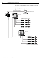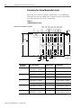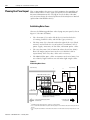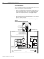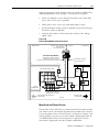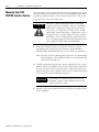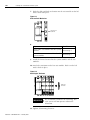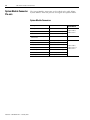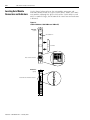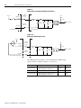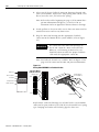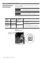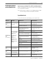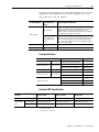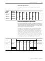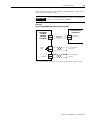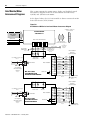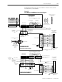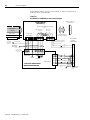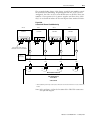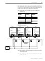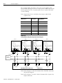
1
1394 SERCOS Interface Multi-Axis Motion Control System (Catalog Numbers 1394C-SJT05-D, 1394C-SJT10-D, 1394C-SJT22-D) Installation Manual Important User Information Because of the variety of uses for the products described in this publication, those responsible for the application and use of this control equipment must satisfy themselves that all necessary steps have been taken to assure that each application and use meets all performance and safety requirements, including any applicable laws, regulations, codes and standards. The illustrations, charts, sample programs and layout examples shown in this guide are intended solely for purposes of example. Since there are many variables and requirements associated with any particular installation, Allen-Bradley does not assume responsibility or liability (to include intellectual property liability) for actual use based upon the examples shown in this publication. Allen-Bradley publication SGI-1.1, Safety Guidelines for the Application, Installation and Maintenance of Solid-State Control (available from your local Allen-Bradley office), describes some important differences between solid-state equipment and electromechanical devices that should be taken into consideration when applying products such as those described in this publication. Reproduction of the contents of this copyrighted publication, in whole or part, without written permission of Rockwell Automation, is prohibited. Throughout this manual we use notes to make you aware of safety considerations: ATTENTION ! Identifies information about practices or circumstances that can lead to personal injury or death, property damage or economic loss. Attention statements help you to: • identify a hazard • avoid a hazard • recognize the consequences IMPORTANT Identifies information that is critical for successful application and understanding of the product. Allen-Bradley is a registered trademark of Rockwell Automation. ControlLogix, Logix, RSLogix, SoftLogix, and SCANport are trademarks of Rockwell Automation. Bussmann is a registered trademark of Cooper Industries, Inc. Hiperface is a registered trademark of Stegmann, Inc. SERCOS interface is a trademark of the Interests Group SERCOS interface e.V. (IGS). Windows is a registered trademark of Microsoft Corporation. UL is a registered trademark of Underwriters Laboratories. Table of Contents Preface Who Should Use this Manual . . . . . . . . . . . . . Purpose of this Manual . . . . . . . . . . . . . . . . . Contents of this Manual . . . . . . . . . . . . . . . . . Product Receiving and Storage Responsibility . Related Documentation . . . . . . . . . . . . . . . . . Conventions Used in this Manual . . . . . . . . . . Allen-Bradley Support . . . . . . . . . . . . . . . . . . Local Product Support . . . . . . . . . . . . . . . Technical Product Assistance . . . . . . . . . . Comments Regarding this Manual . . . . . . . . . . . . . . . . . . . . . . . . . . . . . . . . . . . . . . . . . . . . . . . . . . . . . . . . . . . . . . . . . . . . . . . . . . . . . . . . . . . . . . . . . . . . . . . . . . . . . . . . . . . P-1 P-1 P-2 P-2 P-3 P-3 P-4 P-4 P-4 P-4 Chapter Objectives. . . . . . . . . . . . . . . . . . . . . . . . . . . . . . Complying With European Union Directives . . . . . . . . . . . EMC Directive . . . . . . . . . . . . . . . . . . . . . . . . . . . . . . Meeting CE Requirements . . . . . . . . . . . . . . . . . . . . . . Low Voltage Directive. . . . . . . . . . . . . . . . . . . . . . . . . 1394 System Component Overview . . . . . . . . . . . . . . . . . Before Mounting Your System . . . . . . . . . . . . . . . . . . . . . Unpacking Modules . . . . . . . . . . . . . . . . . . . . . . . . . . System Mounting Requirements. . . . . . . . . . . . . . . . . . Ventilation Requirements . . . . . . . . . . . . . . . . . . . . . . Determining Your System Mounting Hole Layout . . . . . Mounting Your 1394 Through the Back of the Cabinet . HF Bonding Your System. . . . . . . . . . . . . . . . . . . . . . . . . Bonding Modules . . . . . . . . . . . . . . . . . . . . . . . . . . . . Bonding Multiple Subpanels . . . . . . . . . . . . . . . . . . . . Planning Your Panel Layout . . . . . . . . . . . . . . . . . . . . . . . Establishing Noise Zones . . . . . . . . . . . . . . . . . . . . . . Cable Categories for the 1394 . . . . . . . . . . . . . . . . . . . Mounting Guidelines to Reduce Electrical Noise . . . . . Mounting Your 1394 SERCOS interface System . . . . . . . . . Mounting Your External Shunt Resistor Kit . . . . . . . . . . . . . . . . . . . . . . . . . . 1-1 1-2 1-2 1-2 1-3 1-3 1-5 1-5 1-6 1-7 1-8 1-9 1-9 1-9 1-11 1-12 1-12 1-14 1-15 1-18 1-21 Chapter 1 Installing Your 1394 SERCOS Interface System Chapter 2 1394 SERCOS Interface Connector Chapter Objectives. . . . . . . . . . . . . . . . . . . . . . . . . . . . . . . 2-1 Locating System Module Connectors and Indicators . . . . . . 2-2 Data System Module Connector Pin-outs . . . . . . . . . . System Module Connectors . . . . . . . . . . . . . . Discrete Input Connector Pin-out . . . . . . . . . Relay Output Connector Pin-out . . . . . . . . . . Analog Output Connector . . . . . . . . . . . . . . . Motor Feedback Connector Pin-outs . . . . . . . Auxiliary Feedback Connector Pin-outs . . . . . System Module Input Power Pin-outs . . . . . . SCANport Adapter . . . . . . . . . . . . . . . . . . . . Locating Axis Module Connectors and Indicators i . . . . . . . . . . . . . . . . . . . . . . . . . . . . . . . . . . . . . . . . . . . . . . . . . . . . . . . . . . . . . . . . . . . . . . . . . . . . . 2-4 2-4 2-5 2-6 2-7 2-8 2-9 2-11 2-11 2-12 Publication 1394-IN002B-EN-P — February 2004 ii Table of Contents Axis Module Connector Pin-outs. . . . . . . . . . . . Axis Module Connectors . . . . . . . . . . . . . . . Motor Power and Brake Connector Pin-outs. Understanding I/O Specifications . . . . . . . . . . . Discrete Input Specifications . . . . . . . . . . . . Analog Output Specifications. . . . . . . . . . . . Drive System OK Relay Specifications . . . . . Motor Brake Relay Specifications . . . . . . . . . SERCOS Connection Specifications . . . . . . . Logic Power Input Specifications . . . . . . . . . Understanding Feedback Specifications. . . . . . . Motor and Auxiliary Feedback Specifications . . . . . . . . . . . . . . . . . . . . . . . . . . . . . . . . . . . . . . . . . . . . . . . . . . . . . . . . . . . . . . . . . . . . . . . . . . . . . . . . . . . . . . . . . . . . . . . . Chapter Objectives . . . . . . . . . . . . . . . . . . . . . . . . . . . . . Understanding Basic Wiring Requirements . . . . . . . . . . . Building Your Own Cables . . . . . . . . . . . . . . . . . . . . Routing Power and Signal Wiring . . . . . . . . . . . . . . . Input Power Conditioning . . . . . . . . . . . . . . . . . . . . . Determining Your Type of Input Power . . . . . . . . . . . . . Grounded Power Configuration. . . . . . . . . . . . . . . . . Ungrounded Power Configuration . . . . . . . . . . . . . . . Setting the Ground Jumper in Ungrounded Power Configurations . . . . . . . . . . . . . . . . . . . . . . . . . . . Setting the Ground Jumper in 5 and 10 kW System Modules. . . . . . . . . . . . . . . . . . . . . . . . . . Setting the Ground Jumper in 22 kW System Modules Grounding Your 1394 SERCOS Interface System . . . . . . . Grounding Your System to the Subpanel . . . . . . . . . . Grounding Multiple Subpanels . . . . . . . . . . . . . . . . . Motor Power Cable Shield Termination . . . . . . . . . . . Power Wiring Requirements . . . . . . . . . . . . . . . . . . . . . . 1394 Power Wiring Requirements . . . . . . . . . . . . . . . Connecting Input Power. . . . . . . . . . . . . . . . . . . . . . . . . Connecting Power Wiring for 5 and 10 kW System Modules. . . . . . . . . . . . . . . . . . . . . . . . . . Connecting Power Wiring for 22 kW System Modules Connecting Motor Power, Thermal Switch, and Brake . . . Connecting the Ground Wire and Cable Clamp . . . . . Wiring the Motor Power Connector . . . . . . . . . . . . . . Wiring the TB1/TB2 Connectors (1326AB/AS Motors). Wiring the Relay Outputs Connector . . . . . . . . . . . . . Understanding Feedback and I/O Cable Connections . . . Motor Feedback Connector Pin-outs . . . . . . . . . . . . . Wiring Feedback Connectors. . . . . . . . . . . . . . . . . . . Attaching the Cable Shield Clamp . . . . . . . . . . . . . . . Wiring Discrete Input Connectors . . . . . . . . . . . . . . . . . . . . . . . 2-13 2-13 2-13 2-15 2-15 2-17 2-18 2-19 2-20 2-20 2-21 2-21 Chapter 3 Connecting Your 1394 SERCOS Interface System Publication 1394-IN002B-EN-P — February 2004 . . . . . . . . 3-1 3-1 3-2 3-2 3-3 3-4 3-4 3-5 . . 3-6 . . . . . . . . . . . . . . . . . . . . . . . . . 3-6 3-7 3-9 3-9 3-10 3-11 3-13 3-13 3-15 3-15 3-17 3-20 3-20 3-22 3-23 3-25 3-26 3-26 3-29 3-31 3-32 Table of Contents iii Understanding External Shunt Connections. . . . . . . . . . . . 3-34 Connecting Your SERCOS Fiber-Optic Cables . . . . . . . . . . 3-35 Chapter 4 Troubleshooting Status Indicators Chapter Objectives. . . . . . . . . . . . . . . . . . . . . . . . . . . . . . . 4-1 Understanding How to Detect a Problem . . . . . . . Troubleshooting System and Axis Module LEDs . . Troubleshooting the SERCOS Network Status LED. Troubleshooting System and Axis Module Faults . . System Module Faults . . . . . . . . . . . . . . . . . . . Axis Module Faults . . . . . . . . . . . . . . . . . . . . . Troubleshooting General System Problems . . . . . . . . . . . . . . . . . . . . . . . . . . . . . . . . . . . . . . . . . . . . . . . . . . . . . . 4-1 4-2 4-4 4-5 4-5 4-8 4-11 Chapter Objectives. . . . . . . . . . . . . . . . . . . . . . . . . . . . . Certifications . . . . . . . . . . . . . . . . . . . . . . . . . . . . . . . . . Power Specifications . . . . . . . . . . . . . . . . . . . . . . . . . . . System Module Power Specifications . . . . . . . . . . . . . Axis Module Power Specifications . . . . . . . . . . . . . . . Axis Module Series Information. . . . . . . . . . . . . . . . . Circuit Breaker Specifications . . . . . . . . . . . . . . . . . . Fuse Specifications . . . . . . . . . . . . . . . . . . . . . . . . . . Contactor (M1) Specifications . . . . . . . . . . . . . . . . . . Relay Contact Specifications . . . . . . . . . . . . . . . . . . . 24V Logic Input Power Specifications . . . . . . . . . . . . Input Transformer Specifications for 24V Logic Power 1394 System Power Dissipation Specifications . . . . . . General Specifications . . . . . . . . . . . . . . . . . . . . . . . . . . Environmental Specifications. . . . . . . . . . . . . . . . . . . AC Line Filter Specifications . . . . . . . . . . . . . . . . . . . External Shunt Module/Resistor Specifications . . . . . . Maximum Feedback Cable Lengths . . . . . . . . . . . . . . Dimensions . . . . . . . . . . . . . . . . . . . . . . . . . . . . . . . . . . 1394 System Module Dimensions . . . . . . . . . . . . . . . Axis Module Dimensions . . . . . . . . . . . . . . . . . . . . . . . . . . . . . . . . . . . . . . . . . . . A-1 . A-1 . A-2 . A-2 . A-3 . A-3 . A-4 . A-5 . A-5 . A-6 . A-6 . A-6 . A-7 . A-8 . A-8 . A-9 . A-9 A-10 A-11 A-11 A-12 Appendix A Specifications and Dimensions Publication 1394-IN002B-EN-P — February 2004 iv Table of Contents Appendix B Interconnect Diagrams Chapter Objectives . . . . . . . . . . . . . . . . . . . . . . . . . . . 1394 SERCOS Interface Interconnect Diagram Notes . . Power Interconnect Diagrams. . . . . . . . . . . . . . . . . . . Shunt Module Interconnect Diagrams . . . . . . . . . . . . . Axis Module/Motor Interconnect Diagrams . . . . . . . . . Thermal Switch and Brake Interconnect Diagrams . . . . Understanding Motor Thermal Switches . . . . . . . . . How Your Feedback Cable Affects Thermal Switch Wiring. . . . . . . . . . . . . . . . . . . . . . . . . . . . . . . Thermal Switch Interconnect Diagrams . . . . . . . . . Brake Interconnect Diagrams . . . . . . . . . . . . . . . . . . . . . . . . . . . . . . . . . . . . . . . . . . . . B-1 B-2 B-3 B-4 B-6 B-9 B-9 . . . . B-9 . . . . B-9 . . . B-14 Appendix C Catalog Numbers and Accessories Chapter Objectives . . . . . . . . . . . . . . . . . . . . . . . . . . . . . . . C-1 1394 System Modules . . . . . . . . . . . . . . . 1394 Axis Modules . . . . . . . . . . . . . . . . . RSLogix 5000 Software . . . . . . . . . . . . . . AC Line Filters . . . . . . . . . . . . . . . . . . . . External Shunt Modules . . . . . . . . . . . . . Cables . . . . . . . . . . . . . . . . . . . . . . . . . . Motor Power Cables . . . . . . . . . . . . . Motor Feedback Cables . . . . . . . . . . . MP-Series Motor Brake Cable . . . . . . SERCOS Interface Fiber-Optic Cables . Motor End Connector Kits . . . . . . . . . 1394 Accessories . . . . . . . . . . . . . . . . . . Publication 1394-IN002B-EN-P — February 2004 . . . . . . . . . . . . . . . . . . . . . . . . . . . . . . . . . . . . . . . . . . . . . . . . . . . . . . . . . . . . . . . . . . . . . . . . . . . . . . . . . . . . . . . . . . . . . . . . . . . . . . . . . . . . . . . . . . . . . . . . . . . . . . . . . . . . . . . . . . . . . . . . . . . . . . . . . . . . . . . . . . . . . . . . C-1 C-2 C-2 C-2 C-2 C-3 C-3 C-4 C-4 C-4 C-5 C-5 Preface Read this preface to familiarize yourself with the rest of the manual. The preface covers the following topics: Who Should Use this Manual • Who Should Use this Manual • Purpose of this Manual • Contents of this Manual • Product Receiving and Storage Responsibility • Related Documentation • Conventions Used in this Manual • Allen-Bradley Support Use this manual for designing, installing, and wiring your 1394 SERCOS interface Multi-Axis Motion Control System. The manual is intended for engineers or technicians directly involved in the installation and wiring of the 1394. If you do not have a basic understanding of the 1394, contact your local Allen-Bradley representative for information on available training courses before using this product. Purpose of this Manual This manual provides the mounting, wiring, and connecting procedures for the 1394 and standard Rockwell Automation/AllenBradley motors recommended for use with the 1394. For power up procedures, troubleshooting, and system integration with the ControlLogix and SoftLogix SERCOS module/PCI card (see table below) refer to the 1394 SERCOS Interface Integration Manual (publication 1394-IN024x-EN-P). Manuals are available electronically (as a .pdf) or in hardcopy from www.theautomationbookstore.com. 1 Interface ControlLogix Module SoftLogix PCI Card SERCOS interface 1756-MxxSE 1784-PM16SE Publication 1394-IN002B-EN-P — February 2004 P-2 Preface Contents of this Manual Refer to the following listing for the descriptive contents of this installation manual. Chapter Product Receiving and Storage Responsibility Title Contents Preface Describes the purpose, background, and scope of this manual. Also specifies the audience for whom this manual is intended. 1 Installing Your 1394 SERCOS Interface System Provides system mounting information for the 1394 SERCOS interface components. 2 1394 SERCOS Interface Connector Data Provides system module and axis module connector locations, signal descriptions, and I/O specifications. 3 Connecting Your 1394 SERCOS Interface System Provides connection and wiring information for the 1394 SERCOS interface components. 4 Troubleshooting Status Indicators Provides troubleshooting tables that define the 1394 status LEDs and fault codes. Appendix A Specifications and Dimensions Provides mounting dimensions, and power, weight, environmental, and functional specifications for the 1394. Appendix B Interconnect Diagrams Provides power, shunt, and drive/motor interconnect diagrams for the 1394. Appendix C Catalog Numbers and Accessories Provides catalog numbers and descriptions of the 1394 and related products. You, the customer, are responsible for thoroughly inspecting the equipment before accepting the shipment from the freight company. Check the item(s) you receive against your purchase order. If any items are obviously damaged, it is your responsibility to refuse delivery until the freight agent has noted the damage on the freight bill. Should you discover any concealed damage during unpacking, you are responsible for notifying the freight agent. Leave the shipping container intact and request that the freight agent make a visual inspection of the equipment. Store the product in its shipping container prior to installation. If you are not going to use the equipment for a period of time, store using the following guidelines. Publication 1394-IN002B-EN-P — February 2004 • Use a clean, dry location • Maintain an ambient temperature range of -40 to 70° C (-40 to 158° F) • Maintain a relative humidity range of 5% to 95%, non-condensing • Store it where it cannot be exposed to a corrosive atmosphere • Store it in a non-construction area Preface Related Documentation P-3 The following documents contain additional information concerning related Allen-Bradley products. To obtain a copy, contact your local Allen-Bradley office, distributor, or download them from TheAutomationBookstore.com. For: Read This Document: Publication Number: Information on configuring and troubleshooting your 1394 SERCOS interface 1394 SERCOS interface Integration Manual 1394-IN024x-EN-P A description and specifications for the 1394 family including motors and motor accessories Motion Control Selection Guide GMC-SG001x-EN-P Application sizing and configuration information Motion Book Servo Sizing CD (v4.0 or above) Motion Book-mmmyy Information on the use of ControlLogix motion features and application examples ControlLogix Motion Module Programming Manual 1756-RM086x-EN-P ControlLogix SERCOS interface module installation instructions 8 or 16 Axis SERCOS interface Module Installation Instructions 1756-IN572x-EN-P SoftLogix SERCOS interface PCI card installation instructions 16 Axis PCI SERCOS interface Card Installation Instructions 1784-IN041x-EN-P The instructions needed to program a motion application Logix™ Controller Motion Instruction Set Reference Manual 1756-RM007x-EN-P Information on configuring and troubleshooting your ControlLogix motion module ControlLogix Motion Module Setup and Configuration Manual 1756-UM006x-EN-P Information on configuring and troubleshooting your SoftLogix PCI card SoftLogix Motion Card Setup and Configuration Manual 1784-UM003x-EN-P Information on proper handling, installing, testing, and troubleshooting fiber-optic cables Fiber-Optic Cable Installation and Handling Instructions 2090-IN010x-EN-P Information, examples, and techniques designed to minimize system failures caused by electrical noise System Design for Control of Electrical Noise Reference Manual GMC-RM001x-EN-P For declarations of conformity (DoC) currently available from Rockwell Automation Rockwell Automation Product Certification website www.ab.com/ certification/ce/docs An article on wire sizes and types for grounding electrical equipment National Electrical Code Published by the National Fire Protection Association of Boston, MA. A glossary of industrial automation terms and abbreviations Allen-Bradley Industrial Automation Glossary AG-7.1 Conventions Used in this Manual The conventions starting below are used throughout this manual. • Bulleted lists such as this one provide information, not procedural steps • Numbered lists provide sequential steps or hierarchical information • Words that you type or select appear in bold • When we refer you to another location, the section or chapter name appears in italics Publication 1394-IN002B-EN-P — February 2004 P-4 Preface Allen-Bradley Support Allen-Bradley offers support services worldwide, with over 75 Sales/ Support Offices, 512 authorized Distributors and 260 authorized Systems Integrators located throughout the United States alone, plus Allen-Bradley representatives in every major country in the world. Local Product Support Contact your local Allen-Bradley representative for: • Sales and order support • Product technical training • Warranty support • Support service agreements Technical Product Assistance If you need technical assistance, contact your local Allen-Bradley representative or Rockwell Automation Technical Support at (440) 646-5800 / www.ab.com/support. Please have the catalog numbers of your products available when you call. Comments Regarding this Manual To offer comments regarding the contents of this manual, go to www.ab.com/manuals/gmc and download the Motion Control Problem Report form. Mail or fax your comments to the address/fax number given on the form. Publication 1394-IN002B-EN-P — February 2004 Chapter 1 Installing Your 1394 SERCOS Interface System Chapter Objectives This chapter covers the following topics: • Complying With European Union Directives • Before Mounting Your System • Unpacking Modules • System Mounting Requirements • HF Bonding Your System • Planning Your Panel Layout • Mounting Your 1394 SERCOS interface System • Mounting Your External Shunt Resistor Kit ATTENTION ! 1 The following information is a guideline for proper installation. The National Electrical Code and any other governing regional or local codes overrule this information. The Allen-Bradley Company cannot assume responsibility for the compliance or the noncompliance with any code, national, local or otherwise, for the proper installation of this system or associated equipment. If you ignore codes during installation, hazard of personal injury and/or equipment damage exists. Publication 1394-IN002B-EN-P — February 2004 1-2 Installing Your 1394 SERCOS Interface System Complying With European Union Directives If this product is installed within the European Union or EEC regions and has the CE mark, the following regulations apply. For more information on the concept of electrical noise reduction, refer to System Design for Control of Electrical Noise Reference Manual (publication GMC-RM001x-EN-P). EMC Directive This unit is tested to meet Council Directive 89/336 Electromagnetic Compatibility (EMC) using a technical construction file and the following standards, in whole or in part: • EN 50081-2 EMC - Emission Standard, Part 2 - Industrial Environment • EN 50082-2 EMC - Immunity Standard, Part 2 - Industrial Environment • EN 61800-3 EMC - Adjustable Speed Electrical Power Drive Systems - Second Environment, Restricted Distribution Class The product described in this manual is intended for use in an industrial environment. Meeting CE Requirements To meet CE requirements, the following components are required: Publication 1394-IN002B-EN-P — February 2004 • You must install a power line filter (Allen-Bradley catalog number SP-74102-006-01, SP-74102-006-02, SP-74102-006-03 or equivalent based on system current) between the three-phase input line and the system module input. • For MP-Series and 1326AB (M2L/S2L) motors use 2090 series motor power and feedback cables and terminate the cable shields to the chassis clamps provided (refer to Chapter 3 for wiring instructions). • For 1326AB/AS (resolver) motors use 1326 series motor power and feedback cables and terminate the cable shields to the chassis clamps provided (refer to Chapter 3 for wiring instructions). • Combined motor power cable length for all (up to 4) axes must not exceed 360 m (1181 ft). Installing Your 1394 SERCOS Interface System • 1-3 Install the 1394 SERCOS interface system inside an enclosure. Run input power wiring (grounded to the enclosure) in conduit outside of the enclosure. Separate signal and power cables as shown in Planning Your Panel Layout of this chapter. Low Voltage Directive These units are tested to meet Council Directive 73/23/EEC Low Voltage Directive. The EN 50178-1 Electronic Equipment for Use in Power Installations and EN 60204-1 Safety of Machinery-Electrical Equipment of Machines, Part 1-Specification for General Requirements standards apply in whole or in part. Refer to Appendix B of this document for interconnect information. 1394 System Component Overview This section provides an overview of the 1394 system components and a typical installation. 1394 Component: Catalog Numbers: Description: System Module 1394C-SJTxx-D The 1394 multi-axis System Modules are available with 5, 10, or 22 kW continuous output and 360V/ 480V ac input power. Each system module accommodates up to four axis modules. Axis Module 1394C-AMxx The 1394 Axis Modules are available with 2, 3, 5, 15.6, and 23.8 kW continuous output. ControlLogix/ SoftLogix Platforms 1756-MxxSE module 1784-PM16SE PCI card The SERCOS interface module/PCI card serves as a link between the ControlLogix/SoftLogix platform and 1394 system. The communication link uses the IEC 61491 SErial Real-time COmmunication System (SERCOS) protocol over a fiber-optic cable. RSLogix™ 5000 software 9324-RLD300ENE RSLogix 5000 provides support for programming, commissioning, and maintaining the Logix family of controllers. Servo Motors MP-Series, 1326AB, and 1326AS servo motors The MP-Series (low inertia) 460V, 1326AB (M2L/S2L), and 1326AB (resolver) motors are available for use with the 1394 SERCOS interface system. Motor Power, Feedback, and Brake cables Motor power, feedback, and brake cables include integral molded, bayonet style, quick connect/ quick-release connectors at the motor. Power and brake cables have flying leads on the drive end and straight connectors that connect to servo motors. Standard feedback cables have a straight connector on the motor end and flying leads that wire to a feedback connector on the drive end. Fiber-Optic cables SERCOS fiber-optic cables are available in enclosure only, PVC, nylon, and glass with connectors at both ends. SP-74102-006-01 The SP-74102-006-01 three-phase AC line filter is suitable for 1394C-SJT05-D system modules. SP-74102-006-02 The SP-74102-006-02 three-phase AC line filter is suitable for 1394C-SJT10-D system modules. SP-74102-006-03 The SP-74102-006-03 three-phase AC line filter is suitable for 1394C-SJT22-D system modules. 1394-SR10A The Bulletin 1394-SR10A external passive shunt resistor is available when the 1394C-SJT05/10-D internal shunt capability is exceeded. 1394-SR-xxxx One Bulletin 1394 external passive shunt module is required for each 1394C-SJT22-D system module. Cables AC Line Filters External Shunt Modules Note: Refer to Appendix C for a complete list of catalog numbers for the 1394 components listed above. Publication 1394-IN002B-EN-P — February 2004 1-4 Installing Your 1394 SERCOS Interface System The typical 1394 SERCOS interface system installation includes the following components. Figure 1.1 Typical 1394 SERCOS interface System Installation ControlLogix Programming Network Workstation with RSLogix 5000 1756-MxxSE Interface 1394C-SJTxx-D SERCOS System Module ControlLogix Chassis DANGER RISK OF ELECTRICAL SHOCK. HIGH VOLTAGE MAY EXIST UP TO FIVE MINUTES AFTER REMOVING POWER. 1326AB, 1326AS, and MPL-Bxxxx Motors SERCOS ring (Resolver-based or absolute high resolution feedback) SERCOS System Module 1394C-SJTxx-D DANGER RISK OF ELECTRICAL SHOCK. HIGH VOLTAGE MAY EXIST UP TO FIVE MINUTES AFTER REMOVING POWER. 1326AB, 1326AS, and MPL-Bxxxx Motors SERCOS ring SERCOS ring (Resolver-based or absolute high resolution feedback) Publication 1394-IN002B-EN-P — February 2004 Installing Your 1394 SERCOS Interface System Before Mounting Your System 1-5 Before you mount your 1394 SERCOS interface system make sure you understand the following: • how to unpack the 1394 system and axis modules • the system mounting requirements • how to determine your mounting hole layout Unpacking Modules Each 1394 system module ships with the following: • One system module • One system terminator • One installation manual (publication 1394-IN002x-EN-P) • Mating power connectors (5 and 10 kW only) • Mating I/O and feedback connectors • Cable shield grounding clamps Each 1394 axis module ships with the following: • One 1394 axis module • TB1 and TB2 connectors • Cable shield grounding clamp • One 1394 axis module information sheet (publication 1394-5.5) Remove all packing material, wedges, and braces from within and around the components. After unpacking, check the item(s) nameplate catalog number against the purchase order. Refer to Appendix C for more information on catalog numbers. Publication 1394-IN002B-EN-P — February 2004 1-6 Installing Your 1394 SERCOS Interface System System Mounting Requirements There are several things that you need to take into account when preparing to mount the 1394: • The ambient temperature of the location in which you will install the 1394 must not exceed Environmental Specifications as shown in Appendix A. • You must install the panel on a flat, rigid, vertical surface that won’t be subjected to shock, vibration, moisture, oil mist, dust, or corrosive vapors. • You have to mount the system vertically. • You need to maintain minimum clearances (see Figure 1.2) for proper airflow, easy module access, and proper cable bend radius. • The 1394 can operate at elevations to 1000 m (3300 ft) without derating, however, the continuous current rating must be de-rated by 3% for each additional 300 m (1000 ft) up to 3000 m (10,000 ft). Consult your local Allen-Bradley representative prior to operating at over 3000 m (10,000 ft) Refer to Appendix A for mounting dimensions, power dissipation, and environmental specifications for the 1394. ATTENTION ! Publication 1394-IN002B-EN-P — February 2004 Plan the installation of your system so that you can perform all cutting, drilling, tapping, and welding with the system removed from the enclosure. Because the system is of the open type construction, be careful to keep any metal debris from falling into it. Metal debris or other foreign matter can become lodged in the circuitry, which can result in damage to components. Installing Your 1394 SERCOS Interface System 1-7 Ventilation Requirements This section provides information to assist you in sizing your cabinet and locating your 1394 system components. Refer to Figure 1.2 for minimum clearance requirements for power rail components mounted inside the cabinet. Figure 1.2 Minimum System and Axis Module Mounting Requirements DANGER Allow 10.0 mm (0.4 in.) side clearance Allow 10.0 mm (0.4 in.) side clearance Allow 25.4 mm (1.0 in.) clearance at cover tab for opening and closing. RISK OF ELECTRICAL SHOCK. HIGH VOLTAGE MAY EXIST UP TO FIVE MINUTES AFTER REMOVING POWER. Status 50.8 mm (2.0 in.) clearance for airflow and installation Allow 76.2 mm (3.0 in.) clearance for depth of terminator. Status DANGER RISK OF ELECTRICAL SHOCK. HIGH VOLTAGE MAY EXIST UP TO FIVE MINUTES AFTER REMOVING POWER. Wire entry area for cable ground clamps and signal, power, and motor connections. Allow additional clearance below the system module to provide the recommended cable bend radius. Refer to the Motion Control Selection Guide (publication GMC-SG001x-EN-P) for more information. IMPORTANT If the cabinet is ventilated, use filtered or conditioned air to prevent the accumulation of dust and dirt on electronic components. The air should be free of oil, corrosives, or electrically conductive contaminates. Refer to Appendix A for 1394 power dissipation specifications. Publication 1394-IN002B-EN-P — February 2004 1-8 Installing Your 1394 SERCOS Interface System Determining Your System Mounting Hole Layout Based on your actual axis module combination, use the following illustration and table to modify your subpanel using the dimensions that correspond to that specific combination. Figure 1.3 1394 Mounting Hole Layout Dimensions are in millimeters and (inches) 50 (1.97) 0 (0.00) System module mounting holes System outline 385 (15.16) A B C D E A B C D E A B C A D E B A D B C E C 8 TYP (0.32) 67 TYP (2.64) 19.5 (0.768) D E Heatsink Heatsink Heatsink Heatsink cutout for the cutout for the cutout for the cutout for the AM50/75 AM50/75 AM50/75 AM50/75 module module module module only only only only 33.5 TYP (1.32) Axis Module Combination 62.5 100 137.5 175 212.5 250 287.5 (2.46) (3.94) (5.41) (6.89) (8.37) (9.84) (11.32) 125 150 50 275 200 225 (4.92) (5.91) (7.87) (8.86) (10.83) (1.97) 348 (13.70) M6 tapped hole or 1/4-20 UNC - 2B Type of Axis Module Number of Axes Cutout Needed? 1394x-AM50, or -AM75, and 1394C-AM50-IH, or -AM75-IH 0 no 1394x-AM03, AM04, or AM07 up to 4 no 1394x-AM50, or -AM75, and 1394C-AM50-IH, or -AM75-IH 1 yes (1394x-AM50 or -AM75) no (1394C-AM50-IH or -AM75-IH) 1394x-AM03, AM04, or AM07 up to 3 no 1394x-AM50, or -AM75, and 1394C-AM50-IH, or -AM75-IH 2 yes (1394x-AM50 or -AM75) no (1394C-AM50-IH or -AM75-IH) 1394x-AM03, AM04, or AM07 up to 2 no 1394x-AM50, or -AM75, and 1394C-AM50-IH, or -AM75-IH 3 yes (1394x-AM50 or -AM75) no (1394C-AM50-IH or -AM75-IH) 1394x-AM03, AM04, or AM07 up to 1 no 1394x-AM50, or -AM75, and 1394C-AM50-IH, or -AM75-IH 4 yes (1394x-AM50 or -AM75) no (1394C-AM50-IH or -AM75-IH) Note: When mounting axis module combinations, you must mount the 1394x-AM50, -AM75, -AM50-IH, and -AM75IH closest to the system module and ahead of the 1394x-AM03, -AM04, and -AM07 axis modules. Publication 1394-IN002B-EN-P — February 2004 Installing Your 1394 SERCOS Interface System 1-9 Mounting Your 1394 Through the Back of the Cabinet The figure below shows an example of the typical mounting of a 1394 system with 1394x-AM50 or -AM75 axis modules. The 1394x-AM50 and -AM75 have heatsinks that mount through the back of the electrical cabinet. Figure 1.4 Mounting the 1394 with heatsinks through the back of the cabinet Note: This configuration requires a gasket between the 1394x-AM50 or -AM75 and the inside of the enclosure. use the gasket provided. Customer-supplied enclosure HF Bonding Your System Bonding is the practice of connecting metal chassis, assemblies, frames, shields and enclosures to reduce the effects of electromagnetic interference (EMI). For more information on the concept of highfrequency (HF) bonding, the ground plane principle, and electrical noise reduction, refer to System Design for Control of Electrical Noise (publication GMC-RM001x-EN-P). Bonding Modules Unless specified, most paints are not conductive and they act as insulators. To achieve a good bond between power rail and the subpanel, surfaces need to be paint-free or plated. Bonding metal surfaces creates a low-impedance return path for high-frequency energy. IMPORTANT To improve the bond between the 1394 SERCOS interface system and subpanel, construct your subpanel out of zinc plated (paint-free) steel. Improper bonding blocks the direct return path and allows highfrequency energy to travel elsewhere in the cabinet. Excessive highfrequency energy can effect the operation of other microprocessor controlled equipment. Publication 1394-IN002B-EN-P — February 2004 1-10 Installing Your 1394 SERCOS Interface System The illustrations that follow (Figure 1.5) show details of recommended bonding practices for painted panels, enclosures, and mounting brackets. Figure 1.5 Recommended Bonding Practices for Painted Panels Stud-mounting the subpanel to the enclosure back wall Stud-mounting a ground bus or chassis to the subpanel Subpanel Back wall of enclosure Mounting bracket or ground bus Subpanel Welded stud Star washer Nut Scrape paint Flat washer Welded stud Nut Flat washer Use a wire brush to remove paint from threads to maximize ground connection. Use plated panels or scrape paint on front of panel. If the mounting bracket is coated with a non-conductive material (anodized, painted, etc.), scrape the material around the mounting hole. Star washer Bolt-mounting a ground bus or chassis to the back-panel Subpanel Bolt Tapped hole Ground bus or mounting bracket Nut Star washer Scrape paint on both sides of panel and use star washers. Star washer Flat washer Nut Flat washer Star washer Publication 1394-IN002B-EN-P — February 2004 If the mounting bracket is coated with a non-conductive material (anodized, painted, etc.), scrape the material around the mounting hole. Installing Your 1394 SERCOS Interface System 1-11 Bonding Multiple Subpanels Bonding multiple subpanels creates a common low impedance exit path for the high frequency energy inside the cabinet. Subpanels that are not bonded together may not share a common low impedance path. This difference in impedance may affect networks and other devices that span multiple panels. Figure 1.6 Bonding Multiple Subpanels Recommended: Bond the top and bottom of each subpanel to the cabinet using 25.4 mm (1.0 in.) by 6.35 mm (0.25 in.) wire braid Bonded cabinet ground bus to subpanel Scrape the paint around each fastener to maximize metal to-metal-contact. Publication 1394-IN002B-EN-P — February 2004 1-12 Installing Your 1394 SERCOS Interface System Planning Your Panel Layout This section outlines the practices which minimize the possibility of noise-related failures as they apply specifically to 1394 installations. For more information on the concept of electrical noise reduction, refer to System Design for Control of Electrical Noise Reference Manual (publication GMC-RM001x-EN-P). Establishing Noise Zones Observe the following guidelines when laying out your panel (refer to Figure 1.7 for zone locations). • The clean zone (C) is to the left of the 1394 and includes the I/O wiring, feedback cable, and DC filter (grey wireway). • The dirty zone (D) is beneath and to the right of the 1394 (black wireway) and includes the circuit breakers, transformer, 24V dc power supply, contactors, AC line filter, and motor power cables. • The very dirty zone (VD) is limited to where the AC line (EMC) filter VAC output jumpers over to the 1394. Shielded cable is required only if the very dirty cables enter a wireway. • The SERCOS fiber-optic cables are immune to electrical noise, but are relatively fragile and best run with other light weight cables. Figure 1.7 Establishing Noise Zones Clean Wireway Dirty Wireway (1) 1394 SERCOS interface System C D DC Filter 24V Motor Brake PS Circuit Breaker 2 SERCOS System Module 3 Status AC Line Filter DANGER RISK OF ELECTRICAL SHOCK. HIGH VOLTAGE MAY EXIST UP TO FIVE MINUTES AFTER REMOVING POWER. I/O 1 and Feedback Cables Contactors VD D C D Very dirty unshielded power connections segregated (not in wireway) Route Encoder/Analog/Registration Shielded Cable 1 XFMR Route 24V dc I/O Shielded Cable If I/O cable contains (dirty) relay wires, route wires in dirty wireway. This is a clean 24V dc available for any device that may require it. The 24V enters the clean wireway and exits to the left. 3 This is a dirty 24V dc available for motor brakes and contactors. The 24V enters the dirty wireway and exits to the right. 2 Publication 1394-IN002B-EN-P — February 2004 Installing Your 1394 SERCOS Interface System 1-13 Observe the following guidelines when installing your 1756-MxxSE SERCOS interface module (refer to Figure 1.8 for zone locations). • The clean zone (C) is beneath the less noisy modules (I/O, analog, encoder, registration, etc. (grey wireway). • The dirty zone (D) is above the chassis and below the noisy modules (black wireway). • The SERCOS fiber-optic cables are immune to electrical noise, but are relatively fragile and best run with other light weight cables. Figure 1.8 Establishing Noise Zones (ControlLogix) Dirty Wireway Clean Wireway (1) Route dirty wireways directly above the ControlLogix rack (shielded by the chassis) EMC Filter Spare Slot(s) EMC filter/power supply connections segregated (not in clean wireway) Clean I/O (Analog, Encoder Registration, etc.) Dirty I/O (24V dc I/O, AC I/O) Publication 1394-IN002B-EN-P — February 2004 1-14 Installing Your 1394 SERCOS Interface System Cable Categories for the 1394 The table below indicates the zoning requirements of cables connecting to the 1394. Zone Wire/Cable Connections AC input power from filter to system module (unshielded option) AC input power from filter to system module (shielded option) Motor Power (must be shielded) Thermal wires Brake wires (requires suppression) 24V dc logic power Very Dirty Dirty Method Clean Ferrite Sleeve Shielded Cable X U, V, W, PE U1, V1, W1, PE2 X X X X X TB1/TB2 X W1, W2 X COM, PWR (24V dc), filtered 1 Discrete Inputs X COM, PWR (24V dc), unfiltered 2 Discrete Inputs X Motor X X Auxiliary X X Registration Inputs Discrete Inputs X X Enable, Overtravel, and Home inputs Discrete Inputs Analog Outputs Analog Outputs X X Relay Outputs Relay Outputs DPI/SCANport DPI/SCANport X X Feedback Fiber-Optic X X Rx and Tx 1 Refer to Footnote 2 on page 1-12. 2 Refer to Footnote 3 on page 1-12. No Restrictions The table below indicates the zoning requirements of cables connecting to the External Shunt Resistor Kit. Zone Wire/Cable Shunt Power (shielded option) Shunt Power (unshielded option) Connections COL, INT, DC+ Very Dirty Dirty Clean Ferrite Sleeve Shielded Cable X X X X Thermal Switch N/A X Fan (if present) N/A X Publication 1394-IN002B-EN-P — February 2004 Method Installing Your 1394 SERCOS Interface System 1-15 Mounting Guidelines to Reduce Electrical Noise When mounting an AC line (EMC) filter, external shunt resistor, or wiring the motor brake and thermal switch, refer to the sections below for guidelines designed to reduce system failures caused by excessive electrical noise. AC Line Filters Observe the following guidelines when mounting your AC line (EMC) filter (refer to Figure 1.7 for an example). • Mount the AC line filter on the same panel as the 1394 along the right side of the right-most axis module. • Good HF bonding to the panel is critical. For painted panels, refer to Figure 1.5. • Segregate input and output wiring as far as possible. IMPORTANT CE test certification applies only to AC line filter and single 1394 drive. Multiple drive loads may perform satisfactorily, but the user takes legal responsibility. Publication 1394-IN002B-EN-P — February 2004 1-16 Installing Your 1394 SERCOS Interface System External Shunt Modules Observe the following guidelines when mounting your external shunt module (refer to Figure 1.9 and for an example). • Mount circuit components and wiring in the very dirty zone or in an external shielded enclosure. Run shunt power and fan wiring inside metal conduit to minimize the effects of EMI and RFI. • Mount resistors (other than metal-clad) in a shielded and ventilated enclosure outside the cabinet. • Keep unshielded wiring as short as possible. Keep shunt wiring as flat to the cabinet as possible. • Route thermal switch and fan wires separate from shunt power. Figure 1.9 External Shunt Module Outside the Enclosure Customer-supplied metal enclosure 150 mm (6.0 in.) of clearance on all sides of the shunt module (minimum) 1394 Digital Servo Controller 300W Shunt Module ALLEN-BRADLEY R BULLETIN 1394 300W SHUNT MODULE CAT. PART SER. INPUT DC INPUT AC FOR FUSE REPLACEMENT USE: BUSSMAN CAT. NO. FOR USE WITH 1394-SJT22-X SYSTEM MODULE Metal conduit (where required by local code) Shunt thermal switch and fan wires (when exist) Enclosure Clean Wireway Dirty Wireway Shunt Power Wiring Methods: Twisted pair in conduit (1st choice) Shielded twisted pair (2nd choice) Twisted pair, 2 twists per foot min. (3rd choice) (1) C C 1394 SERCOS interface System D DC Filter 24V Motor Brake PS Circuit Breaker SERCOS System Module Status AC Line Filter DANGER RISK OF ELECTRICAL SHOCK. HIGH VOLTAGE MAY EXIST UP TO FIVE MINUTES AFTER REMOVING POWER. I/O and Feedback Cables VD XFMR D C D Very dirty shunt connections segregated (not in wireway) Route 24V dc I/O Shielded Cable Route Encoder/Analog/Registration Shielded Cable Enclosure Publication 1394-IN002B-EN-P — February 2004 Contactors VD Installing Your 1394 SERCOS Interface System 1-17 When mounting your shunt module inside the enclosure, follow these additional guidelines (refer to Figure 1.10 and for an example). • Metal-clad modules can be mounted anywhere in the dirty zone, but as close to the 1394 as possible. • Shunt power wires can be run with motor power cables. • Keep unshielded wiring as short as possible. Keep shunt wiring as flat to the cabinet as possible. • Separate shunt power cables from other sensitive, low voltage signal cables. Figure 1.10 External Shunt Module Inside the Enclosure Clean Wireway Enclosure 150 mm (6.0 in.) of clearance on all sides of the shunt module (minimum) Dirty Wireway 1394 Digital Servo Controller 300W Shunt Module ALLEN-BRADLEY R BULLETIN 1394 300W SHUNT MODULE CAT. PART SER. INPUT DC INPUT AC FOR FUSE REPLACEMENT USE: BUSSMAN CAT. NO. Shunt Power Wiring Methods: Twisted pair in conduit (1st choice) Shielded twisted pair (2nd choice) Twisted pair, 2 twists per foot min. (3rd choice) FOR USE WITH 1394-SJT22-X SYSTEM MODULE Shunt thermal switch and fan wires (when exist) C C D 1394 SERCOS interface System DC Filter 24V Motor Brake PS Circuit Breaker SERCOS System Module Status AC Line Filter DANGER RISK OF ELECTRICAL SHOCK. HIGH VOLTAGE MAY EXIST UP TO FIVE MINUTES AFTER REMOVING POWER. I/O and Feedback Cables VD XFMR Contactors VD D Very dirty shunt connections segregated (not in wireway) Route Encoder/Analog/Registration Shielded Cable D C Route 24V dc I/O Shielded Cable Enclosure Motor Brake and Thermal Switch The thermal switch and brake are mounted inside the motor, but how you connect to the axis module depends on the motor series. Refer to Connecting Motor Power, Thermal Switch, and Brake in Chapter 3 for wiring guidelines specific to your drive/motor combination. Refer to Axis Module/Motor Interconnect Diagrams in Appendix B for the interconnect diagram for your drive/motor combination. Publication 1394-IN002B-EN-P — February 2004 1-18 Installing Your 1394 SERCOS Interface System Mounting Your 1394 SERCOS interface System The procedures in this section assume you have prepared your panel and understand how to bond your system. For installation instructions regarding equipment and accessories not included here, refer to the instructions that came with those items. ATTENTION ! This drive contains ESD (Electrostatic Discharge) sensitive parts and assemblies. You are required to follow static control precautions when you install, test, service, or repair this assembly. If you do not follow ESD control procedures, components can be damaged. If you are not familiar with static control procedures, refer to Allen-Bradley publication 80004.5.2, Guarding Against Electrostatic Damage or any other applicable ESD Protection Handbook. 1. Layout the position for your 1394 in the enclosure (refer to Establishing Noise Zones for panel layout recommendations). Mounting hole dimensions for the 1394 are shown in Appendix A. Note: For help with the mounting hole layout for any combination of axis modules, refer to Determining Your System Mounting Hole Layout on page 1-8. 2. Install the top mounting fasteners on the subpanel for the system module and all axis modules. The heads of the fasteners should be at least 6.35 mm (0.25 in.) from the panel. Make sure the 1394 is properly bonded to the subpanel. Refer to the section HF Bonding Your System for proper bonding techniques. IMPORTANT To improve the bond between the 1394 and subpanel, construct your subpanel out of zinc plated (paint-free) steel. 3. Hang the 1394 system module on the two fasteners on the left side of the subpanel. Publication 1394-IN002B-EN-P — February 2004 Installing Your 1394 SERCOS Interface System 1-19 4. If you are mounting a: Do this: 1394x-AM03, -AM04 or - 1. Hang the axis module on the next mounting fastener. AM07; 1394C-AM50-IH, or -AM75-IH axis module 2. Go to main step 6. 1. Remove the paper backing from the gasket that came with the AM50/75 axis module. 2. Position the gasket so that the sticky side faces the axis module and the small hole side is on top. 1394x-AM50 or -AM75 axis module with the heat sink through the back of the enclosure (refer to Figure 1.4) 3. Slide the gasket over the heat sink and attach it to the back of the axis module. Figure 1.11 Gasket Position gasket 4. Go to main step 5. 5. Hang the AM50/75 axis module on the next mounting fastener. 6. Engage the alignment tab (refer to Figure 1.12). Figure 1.12 Alignment Tab Engaged alignment tab Publication 1394-IN002B-EN-P — February 2004 1-20 Installing Your 1394 SERCOS Interface System 7. Slide the slide-and-lock mechanism on the axis module to the left until it locks into place. Figure 1.13 Slide-and Lock Mechanism SERCOS System Module Slide-and-Lock mechanism Status DANGER RISK OF ELECTRICAL SHOCK. HIGH VOLTAGE MAY EXIST UP TO FIVE MINUTES AFTER REMOVING POWER. 8. If you: Do this: Have more axis modules for this system module Go to step 4. Do not have more axis modules for this system module Go to step 9. 9. Install the lower fasteners for the system module and all axis modules. 10. Attach the terminator to the last axis module. Slide it to the left until it locks in place. Figure 1.14 Attaching the Terminator SERCOS System Module Attach the terminator Status DANGER RISK OF ELECTRICAL SHOCK. HIGH VOLTAGE MAY EXIST UP TO FIVE MINUTES AFTER REMOVING POWER. IMPORTANT The terminator terminates the serial ring. The 1394 system will not operate without the terminator. 11. Tighten all mounting fasteners. Publication 1394-IN002B-EN-P — February 2004 Installing Your 1394 SERCOS Interface System Mounting Your External Shunt Resistor Kit 1-21 If your 1394 requires a means of dissipating regenerative energy that exceeds the capacity of the shunt module, install an External Shunt Resistor Kit (refer to Appendix C for catalog numbers). ATTENTION ! To avoid the hazard of shock or burn and ignition of flammable material, appropriate guarding must be provided. These resistors can reach temperatures in excess of 350° C (662° F). Install per local codes. To install your External Shunt Resistor Kit: 1. Layout the position for your shunt resistor in the enclosure (refer to Establishing Noise Zones for panel layout recommendations). 2. Attach the shunt resistor to the cabinet. The recommended mounting hardware is M6 metric (1/4 in.) bolts. Make sure all fasteners are properly bonded to the subpanel. Refer to the section HF Bonding Your System for proper bonding techniques. 3. Tighten all mounting fasteners. For mounting dimensions, refer to the Motion Control Selection Guide (publication GMC-SG001x-EN-P). Publication 1394-IN002B-EN-P — February 2004 1-22 Installing Your 1394 SERCOS Interface System Publication 1394-IN002B-EN-P — February 2004 Chapter 2 1394 SERCOS Interface Connector Data Chapter Objectives This chapter provides power, feedback, and I/O connector locations and signal descriptions for your 1394 SERCOS interface system. This chapter includes: • Locating System Module Connectors and Indicators • System Module Connector Pin-outs • Locating Axis Module Connectors and Indicators • Axis Module Connector Pin-outs • Understanding I/O Specifications • Understanding Feedback Specifications Switch and LED locations are shown, however for switch and LED configuration, refer to the 1394 SERCOS Interface Integration Manual (publication 1394-IN024x-EN-P). 1 Publication 1394-IN002B-EN-P — February 2004 2-2 1394 SERCOS Interface Connector Data Locating System Module Connectors and Indicators Use the figure below to locate the 1394C-SJT05-D and -SJT10-D System Module connectors and indicators. Figure 2.1 1394 System Modules (1394C-SJT05-D and -SJT10-D) System Module, front view (1394C-SJT05-D and -SJT10-D is shown) 1394 Digital Servo Controller SERCOS interfaceTM ! MORE THAN ONE DISCONNECT SWITCH MAY BE REQUIRED TO DE-ENERGIZE THE EQUIPMENT BEFORE SERVICE. RELAY OUTPUTS 1 DANGER RISK OF ELECTRICAL SHOCK. System Module DRIVE SYSTEM OK ! OUTPUT 3 ELECTRICAL SHOCK HAZARD FROM ENERGY STROAGE CAPACITORS. OUTPUT 2 VERIFY LOW VOLTAGE DISCHARGE BEFORE SERVICING. OUTPUT 1 10 DANGER OUTPUT 0 SEE INSTRUCTIONAL MANUAL. AXIS 3 Enable3 1394 System Module Front Cover 1 5 Home3 Analog Outputs Connector Neg_Otrav3 - Analog_Out_1 - Analog_Out_2 - Analog_Out_3 - Analog_Out_4 - Common - N/C - N/C - N/C - N/C I/O_Com Reg3_Com Reg3_1 Pos_Otrav3 4 8 Reg3_2 AXIS 2 Enable2 1 5 Home2 Neg_Otrav2 Reg2_Com Reg2_1 Pos_Otrav2 I/O_Com 4 8 Reg2_2 AXIS 1 5 Reg1_1 4 8 Neg_Otrav1 1 5 Home0 Relay Outputs Connector Reg1_2 Pos_Otrav0 Neg_Otrav0 I/O_Com 4 8 Reg0_2 RELAY OUTPUTS Reg0_1 Status 4 5 23 I/O_Com AXIS 0 Enable0 Reg0_Com System Module Status LED Pos_Otrav1 6 7 SERCOS Base Node Address Switch SERCOS System Module 1 Home1 8 09 1 Enable1 Reg1_Com DANGER RISK OF ELECTRICAL SHOCK. HIGH VOLTAGE MAY EXIST UP TO FIVE MINUTES AFTER REMOVING POWER. AXIS 1 - SERCOS Receive AXIS 0 Discrete Input Connectors (4) AXIS 2 AXIS 3 Network Status LED SERCOS Receive (Rx) Connector - SERCOS Transmit Tie Down Anchor ON 3 OFF 1 2 SERCOS Transmit (Tx) Connector Tie Down Anchor SERCOS Baud Rate and Optical Power Switches Single Point Bond Bar System Module, bottom view (1394C-SJT05-D and -SJT10-D is shown) Shunt Power Connector DPI/SCANport Connector Logic Power Connector Axis 0 Auxiliary Feedback Input Power Connector Axis 3 Motor Feedback (in four axis system) or Axis 2 Auxiliary Feedback (in three axis system) Axis 1 Auxiliary Feedback Axis 2 Motor Feedback (in four axis system) or Axis 3 Auxiliary Feedback (in two axis system) Axis 1 Motor Feedback Axis 0 Motor Feedback Cable Clamp Grounding Bracket (one clamp installed) Note: Switch and LED locations are shown, however for switch and LED configuration, refer to the 1394 SERCOS Interface Integration Manual (publication 1394-IN024x-EN-P). Publication 1394-IN002B-EN-P — February 2004 1394 SERCOS Interface Connector Data 2-3 Use the figure below to locate the 1394C-SJT22-D System Module connectors and indicators. Figure 2.2 1394 System Modules (1394C-SJT22-D) System Module, front view (1394C-SJT22-D is shown) 1394 Digital Servo Controller SERCOS interfaceTM System Module RELAY OUTPUTS 1 DRIVE SYSTEM OK OUTPUT 3 OUTPUT 2 OUTPUT 1 10 OUTPUT 0 AXIS 3 5 Neg_Otrav3 Reg3_Com Reg3_1 I/O_Com 4 8 1 5 Home2 Reg2_1 I/O_Com 8 1 5 4 8 Home1 Reg2_2 Reg1_1 Pos_Otrav1 Neg_Otrav1 Reg1_Com I/O_Com 4 5 Reg1_2 AXIS 0 Enable0 1 5 Home0 Reg0_1 Pos_Otrav0 Neg_Otrav0 Reg0_Com I/O_Com 4 8 Reg0_2 Relay Outputs Connector Status Network Status LED DANGER RISK OF ELECTRICAL SHOCK. HIGH VOLTAGE MAY EXIST UP TO FIVE MINUTES AFTER REMOVING POWER. Discrete Input Connectors (4) Terminal Block for Logic Power, Input Power, and External Shunt Connections SERCOS Receive (Rx) Connector Tie Down Anchor ON 3 OFF 2 SERCOS Transmit (Tx) Connector 1 System Module Status LED Pos_Otrav2 Neg_Otrav2 4 AXIS 1 Enable1 6 7 SERCOS System Module Reg3_2 AXIS 2 Enable2 Reg2_Com SERCOS Base Node Address Switch Pos_Otrav3 23 1394 System Module Front Cover 1 Home3 8 09 1 Analog Outputs Connector Enable3 SERCOS Baud Rate and Optical Power Switches Single Point Bond Bar System Module, bottom view (1394C-SJT22-D is shown) DPI/SCANport Connector Axis 1 Auxiliary Feedback Axis 0 Auxiliary Feedback Axis 3 Motor Feedback (in four axis system) or Axis 2 Auxiliary Feedback (in three axis system) Axis 2 Motor Feedback (in four axis system) or Axis 3 Auxiliary Feedback (in two axis system) Cable Clamp Grounding Bracket (one clamp installed) Axis 1 Motor Feedback Axis 0 Motor Feedback Note: Switch and LED locations are shown, however for switch and LED configuration, refer to the 1394 SERCOS Interface Integration Manual (publication 1394-IN024x-EN-P). Publication 1394-IN002B-EN-P — February 2004 2-4 1394 SERCOS Interface Connector Data System Module Connector Pin-outs The System Module connectors are described in the table below. System Module connector pin-outs and signal descriptions follow. System Module Connectors Publication 1394-IN002B-EN-P — February 2004 Description Connector Main Input Power 4-position connector housing Logic Power 2-position connector housing Shunt Power 3-position connector housing Logic, Shunt, and Main Input Power Terminal Block 8-position terminal block Single Point Bond Bar 5-position grounding bar Motor/Auxiliary Feedback 13-position connector housing Relay Outputs 10-position connector housing Analog Outputs 9-position connector housing Discrete Input 8-position connector housing (4) SERCOS Transmit and Receive SERCOS fiber-optic (2) DPI/SCANport DPI/SCANport Present on this 1394 System Module 1394C-SJT05-D / 1394C-SJT10-D 1394C-SJT22-D 1394C-SJT05-D, 1394C-SJT10-D, or 1394C-SJT22-D 1394 SERCOS Interface Connector Data 2-5 Discrete Input Connector Pin-out The following table and figure below provides the signal descriptions and pin-out for the Axis 0-3 (8-pin) discrete inputs connector. Refer to Discrete Input Specifications on page 2-15 and Analog Output Specifications on page 2-17 for I/O signal specifications. IMPORTANT The 24V dc supplies for use with discrete inputs and registration inputs are user-supplied. Connect the 24V dc common (pins 3 and 7, not internally connected) as described in the table below. Axis x Pin Description Signal Axis x Pin Description Signal 1 Hardware Enable ENABLEx 5 Positive limit switch POS_OTRAVx 2 Home Switch Input HOMEx 6 Negative limit switch NEG_OTRAVx 3 Common for Registration REGx_COM 7 Common for HOME, ENABLE, and POS/ NEG_OTRAV Signals I/O_COM 4 High Speed Registration 1 Input REGx_1 8 High Speed Registration 2 Input REGx_2 Figure 2.3 Pin Orientation for 8-pin Discrete Inputs Connector Axis 3 Enable3 1 5 Pos_Otrav3 Home3 2 6 Neg_Otrav3 Reg3_Com 3 7 I/O_Com Reg3_1 4 8 Reg3_2 Axis 2 1394 SERCOS interface Control Board Enable2 1 5 Pos_Otrav2 Home2 2 6 Neg_Otrav2 Reg2_Com 3 7 I/O_Com Reg2_1 4 8 Reg2_2 Axis 1 1394C-SJTxx-D Enable1 1 5 Pos_Otrav1 Home1 2 6 Neg_Otrav1 Reg1_Com 3 7 I/O_Com Reg1_1 4 8 Reg1_2 Enable0 1 5 Pos_Otrav0 Home0 2 6 Neg_Otrav0 Reg0_Com 3 7 I/O_Com Reg0_1 4 8 Reg0_2 Axis 0 Publication 1394-IN002B-EN-P — February 2004 2-6 1394 SERCOS Interface Connector Data Relay Output Connector Pin-out The following table and figure below provides the signal descriptions and pin-out for the Relay Output (10-pin) connector. Refer to Drive System OK Relay Specifications on page 2-18 and Motor Brake Relay Specifications on page 2-19 for relay signal specifications. Pin Description Signal 1 When wired properly in the control string, this relay opens the main power contactor if a drive system fault occurs. Refer to figures B.1 and B.2 for examples. DRIVE SYSTEM OK Allows control of motor brake using Enable/Disable parameters for Axis 3. OUTPUT 3 Allows control of motor brake using Enable/Disable parameters for Axis 2. OUTPUT 2 Allows control of motor brake using Enable/Disable parameters for Axis 1. OUTPUT 1 Allows control of motor brake using Enable/Disable parameters for Axis 0. OUTPUT 0 2 3 4 5 6 7 8 9 10 Figure 2.4 Pin Orientation for 10-pin Relay Output Connector 1394 SERCOS interface Control Board 1394C-SJTxx-D Publication 1394-IN002B-EN-P — February 2004 1 2 3 4 5 6 7 8 9 10 Drive System OK Output 3 Output 2 Output 1 Output 0 1394 SERCOS Interface Connector Data 2-7 Analog Output Connector The following table provides the signal descriptions and pin-outs for the analog output (9-pin) connector. Refer to Analog Output Specifications on page 2-17 for analog output signal specifications. Pin Description Signal 1 Test Point ANALOG_OUT_1 2 Test Point ANALOG_OUT_2 3 Test Point ANALOG_OUT_3 4 Test Point ANALOG_OUT_4 5 Common ANALOG_OUT_COM 6 N/C — 7 N/C — 8 N/C — 9 N/C — Figure 2.5 Pin Orientation for 9-pin Analog Output Connector 1 Analog_Out_1 Analog_Out_2 Analog_Out_3 1394 SERCOS interface Control Board Analog_Out_4 Analog_Out_COM 1394C-SJTxx-D N/C N/C N/C 9 N/C Publication 1394-IN002B-EN-P — February 2004 2-8 1394 SERCOS Interface Connector Data Motor Feedback Connector Pin-outs The following table provides the signal descriptions and pin-out for the motor and auxiliary feedback (13-pin) connectors. Motor and Auxiliary Feedback Specifications begin on page 2-21. Stegmann Hiperface (SRS/SRM) Refer to Appendix B for interconnect drawings showing how to connect Stegmann Hiperface® feedback to MPL-Bxxxx-M and -S, -Axxxx-M and -S, and 1326AB-Bxxxx-M2L and -S2L 460V motors. Pin Description Signal Pin Description Signal 1 Sine Differential Input+ SINE+ 8 Hiperface data channel DATA+ 2 Sine Differential Input- SINE- 9 Hiperface data channel DATA- 3 Cosine Differential Input+ COS+ 10 Reserved — 4 Cosine Differential Input- COS- 11 Reserved — 5 Common ECOMM 12 Motor Thermal Switch (normally closed) TS+ 6 Encoder Power (+9V) EPWR_9VM 13 Motor Thermal Switch (normally closed) TS- 7 Reserved — Resolver Transmitter TR = 0.25 Note: TR=0.25 is an abbreviation for Transformation Ratio 0.25. Refer to Appendix B for interconnect drawings showing how to connect resolver transmitter feedback to MPL-Bxxxx-R and 1326AB-Bxxxx-21 Series 460V motors. Pin Description Signal Pin Description Signal 1 Sine Differential Input+ S2 8 Reserved — 2 Sine Differential Input- S4 9 Reserved — 3 Cosine Differential Input+ S1 10 Resolver Excitation R1 4 Cosine Differential Input- S3 11 Resolver Excitation R2 5 Reserved — 12 Motor Thermal Switch (normally closed)1 TS+ 6 Reserved — 13 Motor Thermal Switch (normally closed)1 TS- 7 Reserved — 1 When using 1326AB (resolver-based) motors, the thermal switch wires pass through the TB1/TB2 noise filter circuitry on the bottom of the axis module. IMPORTANT Publication 1394-IN002B-EN-P — February 2004 To meet CE requirements, combined motor power cable length for all (up to 4) axes must not exceed 360 m (1181 ft). 1394 SERCOS Interface Connector Data 2-9 Auxiliary Feedback Connector Pin-outs The following tables provide the signal descriptions and pin-outs for the auxiliary feedback (13-pin) connectors when used with different feedback devices. Motor and Auxiliary Feedback Specifications begin on page 2-21. Note: For TTL devices, the position count will increase when A leads B. For sinusoidal devices, the position count will increase when cosine leads sine. Stegmann Hiperface (SRS and SRM) Pin Description Signal Pin Description Signal 1 Sine Differential Input+ SINE+ 8 Reserved — 2 Sine Differential Input- SINE- 9 Reserved — 3 Cosine Differential Input+ COS+ 10 Hiperface data channel DATA- 4 Cosine Differential Input- COS- 11 Reserved — 5 Hiperface data channel DATA+ 12 Reserved — 6 Common ECOM 13 Reserved — 7 Encoder Power (+5V) EPWR_5V TTL or Sine/Cosine with Index Pulse Pin Description Signal Pin Description Signal 1 A+ / Sine Differential Input+ A+ / SINE+ 8 Reserved — 2 A- / Sine Differential Input- A- / SINE- 9 Reserved — 3 B+ / Cosine Differential Input+ B+ / COS+ 10 Index Pulse- I- 4 B- / Cosine Differential Input- B- / COS- 11 Reserved — 5 Index Pulse+ I+ 12 Reserved — 6 Common ECOM 13 Reserved — 7 Encoder Power (+5V) EPWR_5V Publication 1394-IN002B-EN-P — February 2004 2-10 1394 SERCOS Interface Connector Data Figure 2.6 Pin Orientation for 13-pin Motor/Auxiliary Feedback Connectors Front Axis 0 Auxiliary Feedback Axis 1 Auxiliary Feedback Axis 2 Motor Feedback (in four axis system) or Axis 3 Auxiliary Feedback (in two axis system) Axis 3 Motor Feedback (in four axis system) or Axis 2 Auxiliary Feedback (in three axis system) Axis 1 Motor Feedback Axis 0 Motor Feedback Back Publication 1394-IN002B-EN-P — February 2004 13 12 11 10 9 8 7 6 5 4 3 2 1 1394 System Module Feedback Connectors (bottom view) 1394 SERCOS Interface Connector Data 2-11 System Module Input Power Pin-outs The following table provide the signal descriptions and pin-outs for the system module input power connections. For the location of 1394C-SJT05-D and -SJT10-D input connectors, refer to Figure 2.1 on page 2-2. For the location of 1394C-SJT22-D input terminal block, refer to Figure 2.2 on page 2-3. Refer to Logic Power Input Specifications on page 2-20 for signal specifications. Pin W1 Description Logic power input W2 U Signal W1 W2 U V Three-phase main input power W V W PE Chassis Ground DC+ INT DC+ External Shunt Connections COL INT COL Figure 2.7 1394C-SJTxx-D Input Power W1 W2 U V W PE COL INT DC+ 1394C-SJT05-D and -SJT10-D Input Power Connectors 1394C-SJT22-D Input Power Terminal Blocks SCANport Adapter This port allows you to connect a SCANport device, such as a Human Interface Module (HIM), to the 1394 SERCOS Interface system. Refer to figures 2.1 and 2.2 for SCANport location. Refer to the 1394 SERCOS Interface Integration Manual (publication 1394-IN024x-EN-P) for information on using the HIM. Publication 1394-IN002B-EN-P — February 2004 2-12 1394 SERCOS Interface Connector Data Locating Axis Module Connectors and Indicators Use the figure below to locate the axis module connectors and indicators. Shown below are typical 1394C-AM03, -AM04, and -AM07 axis modules. Although the physical size of the 1394C-AM50-xx and AM75-xx model is larger, the location of the connectors and indicators is identical. Figure 2.8 1394 Axis Modules (1394C-AMxx and -AMxx-IH) Front View (typical) Axis Enabled LED Terminator U1 V1 W1 PE1 PE2 PE3 Motor Power Connections 4 TB1 1 Bottom View (typical) 4 TB2 1 Motor Brake and Thermal Connections Publication 1394-IN002B-EN-P — February 2004 1394 SERCOS Interface Connector Data Axis Module Connector Pin-outs 2-13 The Axis Module connectors are described in the table below. Axis Module connector pin-outs and signal descriptions follow. Axis Module Connectors Description Connector Motor Power Terminal Block 6-position terminal block Motor Brake/Thermal (TB1/TB2) 4-position connector housing (2) Motor Power and Brake Connector Pin-outs The following tables provide the signal descriptions and pin-outs for the Axis Module motor power and brake connections. Refer to Motor Brake Relay Specifications on page 2-19 for signal specifications. Motor Power Connections The following table provides the signal descriptions and pin-outs for the motor power (6-position) terminal block. Terminal Description U1 V1 Signal U1 Three-phase motor power W1 V1 W1 PE1 Axis Ground PE2 Motor Ground PE3 No Connection Cable Clamp Overall Shield IMPORTANT To meet CE requirements, combined motor power cable length for all (up to 4) axes must not exceed 360 m (1181 ft). Publication 1394-IN002B-EN-P — February 2004 2-14 1394 SERCOS Interface Connector Data Motor Brake/Thermal Connectors The following table provides the signal descriptions and pin-outs for the motor brake and thermal (4-pin) TB1 and TB2 connectors. TB1 Pin 1 2 3 4 Thermal Sensor Input from Motor Cable Brake wires from Motor Power Cable Signal TS+ TSBR+ BR- TB2 Pin Description Signal 1 Filtered brake wires from Fault System or System Module Filtered TS+ Filtered thermal sensor output to Fault System or System Module Filtered BR+ 2 3 4 Publication 1394-IN002B-EN-P — February 2004 Description Filtered TS- Filtered BR- 1394 SERCOS Interface Connector Data Understanding I/O Specifications 2-15 A description of the 1394 discrete inputs, analog outputs, relay outputs, SERCOS connections, and logic power connections is provided on the following pages. IMPORTANT To improve registration input EMC performance, refer to the System Design for Control of Electrical Noise Reference Manual (GMC-RM001x-EN-P). Discrete Input Specifications Two fast registration inputs and four other inputs are available for the machine interface on the four discrete input connectors. These are sinking inputs that require a sourcing device. IMPORTANT The discrete input 24V dc power supply is user-supplied. IMPORTANT Overtravel limit input devices must be normally closed and configured in RSLogix 5000. Description: Capture Time Edge/Level Sensitive ENABLE A 24V dc input is applied to these terminals to enable each axis. 50 ms Level Axis 0-3 input pin 2 HOME The Home switch input is a normally open or normally closed contact configured in RSLogix 5000. Inputs for each axis require 24V dc (nominal), 15 mA (max) to energize. Each input is optically isolated and filtered to minimize switch bounce. Refer to Figure 2.9. 50 ms Level Axis 0-3 input pin 5 Axis 0-3 input pin 6 POS_OTRAV NEG_OTRAV The positive/negative limit switch input is a normally closed contact configured in RSLogix 5000. Inputs for each axis require 24V dc (nominal), 15 mA (max) to energize. Each input is optically isolated and filtered to minimize switch bounce. Refer to Figure 2.9. 50 ms Level Axis 0-3 input pin 7 I/O_Com Common grounding point for input signals (Home, Enable, Pos/Neg_Otrav) N/A N/A Axis 0-3 input pin 3 Axis 0-3 input pin 4 Axis 0-3 input pin 8 REG_COM REG_1 REG_2 24V dc high-speed, optically-isolated filtered registration input for each axis. Refer to Figure 2.10. 500 ns Edge Discrete Input Pin: Signal: Axis 0-3 input pin 1 Publication 1394-IN002B-EN-P — February 2004 2-16 1394 SERCOS Interface Connector Data Figure 2.9 Enable, Home, and Overtravel Digital Input Circuits 24V dc I/O Supply Input Discrete Input Pins 1, 2, 5, 6 VCC 1k Ω 3k Ω 1000 pF IO_COM Discrete Input Pin 7 CTRL_INPUT 511 Ω 1394 System Module Customer-Supplied Input Figure 2.10 Registration Digital Input Circuits +24V dc I/O Supply Input Discrete Input Pins 4 and 8 VCC 1k Ω 3k Ω 1000 pF Discrete Input Pin 3 CTRL_INPUT 511 Ω IO_COM Customer-Supplied Registration 1394 System Module The following table provides a description of the digital input specifications, as shown in figures 2.9 and 2.10. Publication 1394-IN002B-EN-P — February 2004 Parameter Description Minimum Maximum ON State Voltage Voltage applied to the input, with respect to IOCOM, to guarantee an ON state. 17.5V dc 38V dc ON State Current Current flow to guarantee an ON State 5.0 mA 15.0 mA OFF State Voltage Voltage applied to the input, with respect to IOCOM, to guarantee an OFF state. — 6.9V dc 1394 SERCOS Interface Connector Data 2-17 Analog Output Specifications The 1394 SERCOS interface drive includes two analog outputs that can be configured through software to represent drive variables. Figure 2.11 shows the configuration of the analog outputs. The table below provides a description of the analog outputs. Note: Refer to Analog Output Connector on page 2-7 for connector pin-outs and figures 2.1 and 2.2 for the connector location. Figure 2.11 Analog Output Configuration Oscilloscope 0V = 0 ref 1394 System Module CH1 CH2 DAC (second channel not shown) IMPORTANT Output values can vary during power-up until the specified power supply voltage is reached. The following table provides a description of the analog output specifications. Parameter Description Minimum Maximum Resolution Number of states that the output signal is divided into, which is 2(to the number of bits). — ±11 bits Output Current Current capability of the output. 0 +2 mA Output Signal Range Range of the output voltage. -10V +10V Offset Error Deviation when the output should be at 0V. — 1 mV Bandwidth Frequency response of the analog output DC 3.6k Hz (3 db) For configuration/setup of the analog outputs, refer to the 1394 SERCOS Interface Integration Manual (publication 1394-IN024x-EN-P). Publication 1394-IN002B-EN-P — February 2004 2-18 1394 SERCOS Interface Connector Data Drive System OK Relay Specifications The Drive System OK output is intended to be wired into the drive’s start/stop string to open the main power contactor if a drive system fault occurs. This configuration will cause the Drive System OK contacts to close after 24V logic power is applied and no system faults are detected. It is capable of handling 120V ac at 1A or less. An active state indicates the drive is operational and does not have a fault. Figure 2.12 Drive System OK Relay Normally Open Relay DRIVE SYSTEM OK_1 DRIVE SYSTEM OK_2 1394 System Module The following table provides a description of the relay output specifications. Parameter Description Minimum Maximum ON State Current Current flow when the relay is closed — 1A ON State Resistance Contact resistance when the relay is closed — 1Ω OFF State Voltage Voltage across the contacts when the relay is open — 120V ac 24V dc — 1A Inductive Maximum switched load Publication 1394-IN002B-EN-P — February 2004 1394 SERCOS Interface Connector Data 2-19 Motor Brake Relay Specifications The connections are rated for +24V, 1A operation. An active signal releases the motor brake. The brake signal uses the turn-on and turn-off delays specified by the brake active delay and brake inactive delay. The delay times are software configurable in RSLogix 5000. For the list of motors rated for 1A operation, the delay times and example diagram, refer to Brake Interconnect Diagrams on page B-15. IMPORTANT For motors requiring more than 1A, a relay must be added. For the list of motors rated at greater than 1A operation, the delay times and example diagram, refer to Brake Interconnect Diagrams on page B-16. Figure 2.13 Relay Outputs Normally Open Relay 3 Axis 3 4 5 7 9 Axis 2 Axis 1 Axis 0 6 8 10 1394 System Module The following table provides a description of the relay output specifications. Parameter Description Minimum Maximum ON State Current Current flow when the relay is closed — 1A ON State Resistance Contact resistance when the relay is closed — 1Ω OFF State Voltage Voltage across the contacts when the relay is open — 30V — 1A Inductive Maximum switched load Refer to Brake Interconnect Diagrams beginning on page B-14 for wiring examples. Publication 1394-IN002B-EN-P — February 2004 2-20 1394 SERCOS Interface Connector Data SERCOS Connection Specifications Two fiber-optic connectors (transmit and receive) are provided on the 1394 system module. The table below lists SERCOS communication specifications. Specification Description Data Rates 2, 4, and 8 MBd Node Addresses Determined by hardware configuration. Refer to the 1394 SERCOS Interface Integration Manual (publication 1394-IN0024x-EN-P). Logic Power Input Specifications The 1394 system module must be wired with a logic power input. Refer to figures 2.1 and 2.2 for the location of the logic power connector/terminal blocks and page A-6 for the 24V Logic Input Power Specifications. Publication 1394-IN002B-EN-P — February 2004 1394 SERCOS Interface Connector Data Understanding Feedback Specifications 2-21 The 1394 SERCOS interface system module can accept motor feedback signals from the following types of encoders: • Stegmann Hiperface • Resolver Transmitter TR = 0.25 • TTL AQB or Sine/Cosine (Feedback Only axis configuration in RSLogix 5000) The 1394 SERCOS interface system module can accept auxiliary feedback signals from the following types of encoders: • Stegmann Hiperface • TTL AQB or Sine/Cosine with index pulse Note: Auto-configuration in RSLogix 5000 software of intelligent absolute or high-resolution is possible only with Allen-Bradley motors. Motor and Auxiliary Feedback Specifications The table below lists motor encoder feedback specifications. Specification Description Encoder Types Sine/Cosine, Intelligent, Resolver, and Absolute Maximum Input Frequency 200 kHz (Sine/Cosine input) Publication 1394-IN002B-EN-P — February 2004 2-22 1394 SERCOS Interface Connector Data The following table provides a description of the AM, BM, and IM inputs for auxiliary (TTL) motor encoders. Parameter Description Minimum Maximum AM, BM, and IM ON State Input Voltage Input voltage difference between the + input and the - input that is detected as an ON state. +1.0V +7.0V AM, BM, and IM OFF State Input Voltage Input voltage difference between the + input and the - input that is detected as an OFF state. -1.0V -7.0V Common Mode Input Voltage Potential difference between any encoder signal and logic ground. -7.0V +12.0V DC Current Draw Current draw into the + or - input. -30 mA 30 mA AM, BM Input Signal Frequency Frequency of the AM or BM signal inputs. The count frequency is 4 times this frequency, since the circuitry counts all four transitions. — 1.0 MHz IM Pulse Width Pulse width of the index input signal. Since the index is active for a percentage of a revolution, the speed will determine the pulse width. 125 nS — AM, BM Phase Error 2.5 MHz Line Frequency Amount that the phase relationship between the AM and BM inputs can deviate from the nominal 90°. -22.5° +22.5° AM, BM Phase Error 1 MHz Line Frequency Amount that the phase relationship between the AM and BM inputs can deviate from the nominal 90°. -45° +45° The following table provides a description of the AM and BM inputs for Sine/Cosine encoders when used as motor or auxiliary feedback. Parameter Description Minimum Maximum Sine/cosine Input Signal Frequency Frequency of the Sine or Cosine signal inputs. — 200 kHz Sine/cosine Input Voltage Peak-to-peak input voltages of the Sine or Cosine inputs. 0.5V (p-p) 2.0V (p-p) Feedback Power Supply The 1394 system module generates the +5V and +9V dc for the motor and auxiliary feedback power supplies. Short circuit protection and separate common mode filtering for each channel is included. Refer to the table below for specifications. Supply Reference +5V dc +9V dc 1 2 Publication 1394-IN002B-EN-P — February 2004 Voltage Current mA Minimum Nominal Maximum Minimum Maximum EPWR_5V 5.13 5.4 5.67 10 400 1 EPWR_9V 8.3 9.1 9.9 10 275 2 5 volt total for all axes. 9 volt total for all axes. Chapter 3 Connecting Your 1394 SERCOS Interface System Chapter Objectives Understanding Basic Wiring Requirements This chapter covers the following topics: • Understanding Basic Wiring Requirements • Determining Your Type of Input Power • Setting the Ground Jumper in Ungrounded Power Configurations • Grounding Your 1394 SERCOS Interface System • Power Wiring Requirements • Connecting Input Power • Connecting Motor Power, Thermal Switch, and Brake • Understanding Feedback and I/O Cable Connections • Understanding External Shunt Connections • Connecting Your SERCOS Fiber-Optic Cables This section contains basic wiring information for the 1394. ATTENTION ! IMPORTANT 1 Plan the installation of your system so that you can perform all cutting, drilling, tapping, and welding with the system removed from the enclosure. Because the system is of the open type construction, be careful to keep any metal debris from falling into it. Metal debris or other foreign matter can become lodged in the circuitry, which can result in damage to components. This section contains common PWM servo system wiring configurations, size, and practices that can be used in a majority of applications. National Electrical Code, local electrical codes, special operating temperatures, duty cycles, or system configurations take precedence over the values and methods provided. Publication 1394-IN002B-EN-P — February 2004 3-2 Connecting Your 1394 SERCOS Interface System Building Your Own Cables IMPORTANT Factory made cables are designed to minimize EMI and are recommended over hand-built cables to ensure system performance. When building your own cables, follow the guidelines listed below. • Connect the cable shield to the motor end connector with a complete 360° connection and the cable clamp on the drive end. • Use a twisted pair cable whenever possible. Twist differential signals with each other and twist single-ended signals with the appropriate ground return. Refer to Appendix C for MP-Series and 1326AB (M2L/S2L) motor end connector kit descriptions and catalog numbers. Routing Power and Signal Wiring Be aware that when you route power and signal wiring on a machine or system, radiated noise from nearby relays, transformers, and other electronic drives, can be induced into motor or encoder feedback, communications, or other sensitive low voltage signals. This can cause system faults and communication problems. Refer to Chapter 1 for examples of routing high and low voltage cables in wireways. Refer to System Design for Control of Electrical Noise (publication GMC-RM001x-EN-P) for more information. Publication 1394-IN002B-EN-P — February 2004 Connecting Your 1394 SERCOS Interface System 3-3 Input Power Conditioning In most applications, you can connect the 1394 system module directly to a three-phase, AC power line. However, if certain power line conditions exist, the input power component can malfunction. If either of the following is true, you can use a line reactor or isolationtype transformer to reduce the possibility of this type of malfunction: • The AC line supplying the drive has power factor correction capacitors. • The AC line frequently experiences transient power interruptions or significant voltage spikes. IMPORTANT Line conditioning is not typically required. If you have experienced power problems in the past on a power distribution line, you may need to consider input power conditioning. Publication 1394-IN002B-EN-P — February 2004 3-4 Connecting Your 1394 SERCOS Interface System Determining Your Type of Input Power Before you ground or wire your 1394 system you must determine the type of power distribution system you will be connecting to for main input power. The 1394 system is designed to operate in both grounded and ungrounded environments. Grounded Power Configuration The grounded power configuration allows you to ground your threephase power at a neutral point. The 1394 system module has a factory installed jumper configured for grounded power distribution. If you determine that you have grounded power distribution in your plant you do not need to modify your system. Figure 3.1 Grounded Power Configuration SERCOS System Module Status DANGER System module single point bond bar RISK OF ELECTRICAL SHOCK. HIGH VOLTAGE MAY EXIST UP TO FIVE MINUTES AFTER REMOVING POWER. Conduit/4-Wire Cable U V W PE1 Cable clamp around shield PE2 W1 V1 U1 1326 or MP-Series motor power cable Shield Bonded cabinet ground bus Ground grid or power distribution ground Note: The input power terminal designated PE is electrically common to the system module single point bond bar. Publication 1394-IN002B-EN-P — February 2004 Connecting Your 1394 SERCOS Interface System 3-5 Ungrounded Power Configuration The ungrounded power configuration does not allow for a neutral ground point. If you determine that you have ungrounded power distribution in your plant, you need to move the factory installed jumper to the ungrounded power distribution position to prevent electrostatic buildup inside the 1394. Refer to the instructions on page 3-6 for 5 and 10 kW system modules, and starting on page 3-7 for 22 kW system modules. Figure 3.2 Ungrounded Power Configuration SERCOS System Module Status DANGER System module single point bond bar RISK OF ELECTRICAL SHOCK. HIGH VOLTAGE MAY EXIST UP TO FIVE MINUTES AFTER REMOVING POWER. Conduit/4-Wire Cable U PE1 V Cable clamp around shield 1326 or MP-Series motor power cable PE2 W1 V1 U1 W Shield Bonded cabinet ground bus Ground grid or power distribution ground ATTENTION ! Ungrounded systems do not reference each phase potential to a power distribution ground. This can result in an unknown potential to earth ground. Note: The input power terminal designated PE is electrically common to the system module single point bond bar. Publication 1394-IN002B-EN-P — February 2004 3-6 Connecting Your 1394 SERCOS Interface System Setting the Ground Jumper in Ungrounded Power Configurations These procedures assumes that you have bonded and mounted your system module to the subpanel and that there is no power applied to the system. IMPORTANT If you have grounded power distribution, you do not need to set the ground jumper. Go to Grounding Your 1394 SERCOS Interface System. Setting the Ground Jumper in 5 and 10 kW System Modules This procedures applies to 1394C-SJT05-D and -SJT10-D system modules. To set the ground jumper for an ungrounded system: 1. Verify that all 24V logic and main input power has been removed from the system. 2. Open the system module door. 3. Remove the three control board screws (refer to Figure 3.3 for locations). 4. Remove ribbon cable from control board (refer to Figure 3.3 for location). Note: You should not find it necessary to remove both ends of the ribbon cable. Remove only the control board end. 5. Remove the control board for easy access to ground jumpers (pull it straight out from system module). 6. Locate the jumper connecting J4 and J5 on the assembly adjacent to the control board, and move one end of the jumper from J5 to J6 (refer to Figure 3.3 for locations). 7. Re-install the control board. Align the guide pins in the rear of the enclosure with the holes in the control board. 8. Re-install ribbon cable into the control board connector. 9. Re-install the three control board screws. 10. Close the system module door. 11. Go to Grounding Your 1394 SERCOS Interface System. Publication 1394-IN002B-EN-P — February 2004 Connecting Your 1394 SERCOS Interface System 3-7 Figure 3.3 Ground Jumper Locations for the 5 and 10 kW System Modules 1394 Digital Servo Controller SERCOS interfaceTM ! MORE THAN ONE DISCONNECT SWITCH MAY BE REQUIRED TO DE-ENERGIZE THE EQUIPMENT BEFORE SERVICE. RELAY OUTPUTS 1 DRIVE SYSTEM OK ! OUTPUT 3 1394C-SJTxx-D (5 and 10 kW) DANGER ELECTRICAL SHOCK HAZARD FROM ENERGY STROAGE CAPACITORS. OUTPUT 2 VERIFY LOW VOLTAGE DISCHARGE BEFORE SERVICING. OUTPUT 1 10 DANGER RISK OF ELECTRICAL SHOCK. System Module OUTPUT 0 SEE INSTRUCTIONAL MANUAL. AXIS 3 Enable3 1 5 4 8 Home3 Reg3_1 Pos_Otrav3 Neg_Otrav3 Reg3_Com - Analog_Out_1 - Analog_Out_2 - Analog_Out_3 - Analog_Out_4 - Common - N/C - N/C - N/C - N/C I/O_Com Reg3_2 AXIS 2 Enable2 1 5 Home2 Neg_Otrav2 Reg2_Com Reg2_1 I/O_Com 4 8 Upper Control Board Screw Reg2_2 AXIS 1 1 5 Home1 Neg_Otrav1 I/O_Com 4 8 45 23 Reg1_Com Reg1_1 Pos_Otrav1 Reg1_2 90 1 Enable1 678 Ribbon Cable Connector Pos_Otrav2 - SERCOS Base Address x10 AXIS 0 Enable0 1 5 4 8 Home0 I/O_Com Reg0_2 RELAY OUTPUTS Reg0_1 Pos_Otrav0 Neg_Otrav0 Reg0_Com - SERCOS Receive Lower Control Board Screw AXIS 0 Side Control Board Screw AXIS 1 AXIS 2 AXIS 3 SERCOS Network Status J4 - SERCOS Transmit J5 Ground Jumper Terminals J6 ON 1 2 3 OFF Setting the Ground Jumper in 22 kW System Modules This procedures applies to 1394C-SJT22-D system module. To set the ground jumper for an ungrounded system: 1. Verify that all 24V logic and main input power has been removed from the system. 2. Open the system module door. 3. Locate the ground jumper inside the system module (refer to Figure 3.4 for jumper location). 4. Without removing the circuit board, unplug the jumper and move it to the ungrounded power distribution position. Refer to Figure 3.5 for the jumper positions. IMPORTANT Do not remove circuit board from 1394 system module. Publication 1394-IN002B-EN-P — February 2004 3-8 Connecting Your 1394 SERCOS Interface System Figure 3.4 Location of the 22 kW System Module Ground Jumper 1394C-SJT22-D Ground Jumper Figure 3.5 22 kW System Module Jumper Positions Front edge of board Factory default jumper position for a grounded configuration Front edge of board Jumper position on ungrounded power configuration 5. Close the system module door. 6. Go to Grounding Your 1394 SERCOS Interface System. Publication 1394-IN002B-EN-P — February 2004 Connecting Your 1394 SERCOS Interface System Grounding Your 1394 SERCOS Interface System 3-9 We recommend that all equipment and components of a machine or process system have a common earth ground point connected to their chassis. A grounded system provides a safety ground path for short circuit protection. Grounding your modules and panels minimizes shock hazards to personnel and damage to equipment caused by short circuits, transient overvoltages, and accidental connection of energized conductors to the equipment chassis. For CE grounding requirements, refer to Chapter 1. IMPORTANT To improve the bond between your 1394 and the subpanel, construct your subpanel out of zinc plated (paint-free) steel. Grounding Your System to the Subpanel This section provides examples for connecting the chassis ground to your 1394 and the subpanel. The 1394 system module provides a grounding bar as a common point of chassis ground for the system and axis modules, as shown in Figure 3.6. ATTENTION ! The National Electrical Code contains grounding requirements, conventions, and definitions. Follow all applicable local codes and regulations to safely ground your system. Refer to Appendix B for the 1394 interconnect diagrams. Figure 3.6 1394 Ground Wire Connections 1394 Front View PE1 System module single point bond bar PE1 PE1 PE1 To bonded cabinet ground bus or power distribution ground The system module single point bond bar wires to the bonded system ground bus on the sub-panel. Refer to Figure 3.7 for grounding configuration examples. Publication 1394-IN002B-EN-P — February 2004 3-10 Connecting Your 1394 SERCOS Interface System Figure 3.7 PE Safety Ground Configuration with Multiple 1394 Systems on One Panel 1394C-SJTxx-x System Modules SERCOS System Module SERCOS System Module Status Status DANGER RISK OF ELECTRICAL SHOCK. HIGH VOLTAGE MAY EXIST UP TO FIVE MINUTES AFTER REMOVING POWER. DANGER RISK OF ELECTRICAL SHOCK. HIGH VOLTAGE MAY EXIST UP TO FIVE MINUTES AFTER REMOVING POWER. Bonded ground bar (optional) All ground wiring must comply with local codes SERCOS System Module SERCOS System Module Status Status DANGER RISK OF ELECTRICAL SHOCK. HIGH VOLTAGE MAY EXIST UP TO FIVE MINUTES AFTER REMOVING POWER. DANGER RISK OF ELECTRICAL SHOCK. HIGH VOLTAGE MAY EXIST UP TO FIVE MINUTES AFTER REMOVING POWER. System module single point bond bar Always follow NEC and applicable local codes Ground grid or power distribution ground Bonded cabinet ground bus Grounding Multiple Subpanels To extend the chassis ground to multiple subpanels, refer to the figure below. Figure 3.8 Subpanels Connected to a Single Ground Point Always follow NEC and applicable local codes Ground grid or power distribution ground Publication 1394-IN002B-EN-P — February 2004 Connecting Your 1394 SERCOS Interface System 3-11 Motor Power Cable Shield Termination Factory supplied motor power cables for MP-Series and 1326AB/AS motors are shielded, and the braided cable shield must terminate at the drive during installation. A small portion of the cable jacket must be removed to expose the shield braid. The exposed area must be clamped (using the clamp provided) in front of the axis module, as shown in Figure 3.9, and the power wires terminated in the axis module terminal block. ATTENTION ! IMPORTANT To avoid hazard of electrical shock, ensure shielded power cables are grounded at a minimum of one point for safety. Cable clamps, designed to accommodate cables 1.5 to 6 mm2 (16 to 10 AWG) in size, are shipped with each axis module. If your axis module (1394x-AM75) /motor combination requires 10 mm2 (8 AWG) cable, a larger cable clamp (catalog number 1394C-8AWGGCLAMP) is necessary to accommodate the larger diameter cable. Connecting MP-Series (Low Inertia) and 1326AB Motor Power When using MP-Series (low inertia) or 1326AB (M2L/S2L) motors, only the three-phase motor power wires are included in power cable, as shown in the figure below. These motors have a separate connector on the motor for brake connections and thermal switch wires are included in the feedback cable. Figure 3.9 Motor Power Cable (2090-XXNPMP-xxSxx or -CDNBPMP-xxSxx) 1394 Front View Motor Power Cable Clamp Publication 1394-IN002B-EN-P — February 2004 3-12 Connecting Your 1394 SERCOS Interface System Connecting 1326AB/AS (resolver) Motor Power When using 1326AB/AS motors with resolver feedback, the thermal switch and brake wires are included in the motor power cable (1326CPx1-xxx). To improve the EMC performance of your system, route the motor brake and thermal switch wires to TB1 (as shown in Figure 3.10) and reference Thermal Switch and Brake Interconnect Diagrams on page B-9 for the interconnect diagram. Figure 3.10 Motor Power Cable (1326-CPx1-xxx) SERCOS System Module Status DANGER TB2 Motor Brake and Thermal Switch Wires TB1 RISK OF ELECTRICAL SHOCK. HIGH VOLTAGE MAY EXIST UP TO FIVE MINUTES AFTER REMOVING POWER. 1326-CPx1-xxx Motor Power Cable TB2 TB1 1326-CPx1-xxx Motor Power Cable Publication 1394-IN002B-EN-P — February 2004 Connecting Your 1394 SERCOS Interface System Power Wiring Requirements 3-13 Power wiring requirements are given in the tables below. Wire should be copper with 75° C (167° F) minimum rating, per NFPA 79 unless otherwise noted. Phasing of main input power is arbitrary and earth ground connection is required for safe and proper operation. IMPORTANT The National Electrical Code and local electrical codes take precedence over the values and methods provided. 1394 Power Wiring Requirements Module System Module 1394C-SJT05-D or 1394C-SJT10-D System Module 1394C-SJT22-D System Module 1394C-SJTxx-D Axis Module 1394C-AM03, -AM04, and -AM07 Axis Module 1394C-AM50, -AM75, -AM50-IH, and -AM75-IH Axis Module 1394C-AMxx and -AMxx-IH Recommended Wire Size mm2 (AWG) Description Connects to Terminals Main Input Power U, V, W, PE 1 6 (10) Input Logic Power W1, W2 4 (12) Shunt Resistor Connections COL, INT, DC+ 6 (10) 2 Main Input Power U, V, W, PE 1 10 (8) Input Logic Power W1, W2 4 (12) External Shunt Module Connections DC+, COL 10 (8) 2 Ground Single Point Bond Bar 10 (8) Drive System OK and Brake Relay Circuits Relay Outputs 0.2-4.0 (26-12) Motor Power U1, V1, W1, and PE2 Motor power cable depends on motor/drive combination, 6 (10) maximum Ground PE1 6 (10) Motor Power U1, V1, W1, and PE2 Motor power cable depends on motor/drive combination, 10 (8) maximum Ground PE1 10 (8) Thermal Switch and Brake Filter Circuits TB1/TB2 0.2-4.0 (26-12) Torque Value Nm (lb-in.) 0.56 - 0.62 (5.0 - 5.6) 2.21 - 2.66 (20.0 - 24.0) 1.6 (14) 0.56 - 0.62 (5.0 - 5.6) 1.55 - 2.0 (14.0 - 18.0) 0.56 - 0.62 (5.0 - 5.6) 1 The input power terminal designated PE is electrically common to the system module single point bond bar, so the ground connection at PE is optional. However, the ground connection at the single point bond bar is mandatory. 2 105° C (221° F), 600V. Note: Refer to the section Understanding External Shunt Connections on page 3-34 for more information regarding the COL, INT, and DC+ connections. Publication 1394-IN002B-EN-P — February 2004 3-14 Connecting Your 1394 SERCOS Interface System For additional information refer to Power Specifications in Appendix A. Refer to Appendix B for the 1394 interconnect diagrams. ATTENTION ! ATTENTION ! Publication 1394-IN002B-EN-P — February 2004 This drive contains ESD (Electrostatic Discharge) sensitive parts and assemblies. You are required to follow static control precautions when you install, test, service, or repair this assembly. If you do not follow ESD control procedures, components can be damaged. If you are not familiar with static control procedures, refer to Allen-Bradley publication 80004.5.2, Guarding Against Electrostatic Damage or any other applicable ESD Protection Handbook. To avoid personal injury and/or equipment damage, ensure motor power connectors are used for connection purposes only. Do not use them to turn the unit on and off. To avoid personal injury and/or equipment damage, ensure shielded power cables are grounded to prevent potentially high voltages on the shield. Connecting Your 1394 SERCOS Interface System Connecting Input Power 3-15 The system module provides terminating points for the main input power, logic power, feedback, and various other control signals. The slide-and-lock mechanism transfers power and commutation signals to each axis module. This procedure assumes you have the 1394 SERCOS interface system mounted on your panel and are ready to wire the input power. Each individual application requires different wiring. This section provides guidelines for wiring your system. Because of the diversity of applications and systems, no single method of wiring is applicable in all cases. IMPORTANT When tightening screws to secure the wires, refer to the tables beginning on page 3-13 for torque values. IMPORTANT To ensure system performance, run wires and cables in the wireways as established in Chapter 1. Refer to Appendix B for the 1394 interconnect diagrams. If you have this System Module: Then Go To: 1394C-SJT05-D (5 kW) or 1394C-SJT10-D (10 kW) Connecting Power Wiring for 5 and 10 kW System Modules beginning below. 1394C-SJT22-D (22 kW) Connecting Power Wiring for 22 kW System Modules beginning on page 3-17. Connecting Power Wiring for 5 and 10 kW System Modules The 1394C-SJT05-D and 1394C-SJT10-D system modules use connectors for wiring the main input power and logic power. You will wire the system using connector plugs that mate with connector housings. Refer to Figure 2.1 for the connector locations. ATTENTION ! To avoid personal injury and/or equipment damage ensure installation complies with specifications regarding wire types, conductor sizes, branch circuit protection, and disconnect devices. The National Electrical Code (NEC) and local codes outline provisions for safely installing electrical equipment. Publication 1394-IN002B-EN-P — February 2004 3-16 Connecting Your 1394 SERCOS Interface System Wiring Main Input Power To wire the main input power connector: 1. Prepare the incoming three-phase power wires for attachment to the input power connector by removing 10 mm (0.375 in.) of insulation. IMPORTANT Use caution not to nick, cut, or otherwise damage strands as you remove the insulation. 2. Route the three-phase power wires (U, V, W, and PE) to your 1394 system module. 3. Connect the system module ground wire from the system module single point bond bar to the bonded ground bar or bonded cabinet ground bus on the subpanel (as shown in Figure 3.7). For more information on bonding, refer to Chapter 1. 4. Insert the incoming power wires into the input power connector plug as follows and tighten the four connector plug screws. Insert the wires labeled: Into connector terminals labeled: U U V V W W Ground PE 5. Gently pull on each wire to make sure it does not come out of its terminal. Re-insert and tighten any loose wires. ATTENTION ! To avoid personal injury or damage to equipment, verify that keys are inserted into the beveled slots above terminals V and W of the input power connector plug and PE and COL on the system module input and shunt power connectors, respectively. If the keys are missing, refer to Installing Your 1394C Power Connector Key Kit Installation Instructions (publication 1394-IN023x-EN-P). 6. Insert the input power connector plug into the input power connector on the bottom of the system module (refer to Figure 2.1 for the connector location). Publication 1394-IN002B-EN-P — February 2004 Connecting Your 1394 SERCOS Interface System 3-17 Wiring Logic Power To wire the logic power connector: 1. Prepare the incoming 24V dc logic power wires for attachment to the logic power connector by removing 10 mm (0.375 in.) of insulation. IMPORTANT Use caution not to nick, cut, or otherwise damage strands as you remove the insulation. 2. Route the 24V dc power wires (W1 and W2) to your 1394 system module. 3. Insert the incoming 24V dc logic power wires into the logic power connector plug as follows and tighten the connector plug screws. Insert the wires labeled: Into the connector terminals labeled: W1 W1 W2 W2 4. Gently pull on each wire to make sure it does not come out of its terminal. Re-insert and tighten any loose wires. 5. Insert the logic power connector plug into the logic power connector on the bottom of the system module (refer to Figure 2.1 for the connector location). 6. Go to Connecting Motor Power, Thermal Switch, and Brake. Connecting Power Wiring for 22 kW System Modules The 1394C-SJT22-D system module use IEC terminal blocks instead of connectors for making power connections. You will wire the system module using the power terminal blocks. Refer to Figure 2.2 for the terminal block location. ATTENTION ! To avoid personal injury and/or equipment damage, ensure installation complies with specifications regarding wire types, conductor sizes, branch circuit protection, and disconnect devices. The National Electrical Code (NEC) and local codes outline provisions for safely installing electrical equipment. Publication 1394-IN002B-EN-P — February 2004 3-18 Connecting Your 1394 SERCOS Interface System Wiring Main Input Power To wire the main input power terminal block: 1. Prepare the incoming three-phase power wires for attachment to the input power terminals by removing 10 mm (0.375 in.) of insulation. IMPORTANT Use caution not to nick, cut, or otherwise damage strands as you remove the insulation. 2. Route the three-phase power wires (U, V, W, and PE) to your 1394 system module. 3. Connect the system module ground wire from the system module single point bond bar to the bonded ground bar or bonded cabinet ground bus on the subpanel (as shown in Figure 3.7). For more information on bonding, refer to Chapter 1. 4. Open the front door of the system module and locate the 22 kW system module terminal blocks (refer to Figure 2.2). 5. Insert the incoming power wires into the terminal blocks as follows and tighten the four terminal block screws. Insert the wires labeled: Into the terminal blocks labeled: U U V V W W Ground PE 6. Gently pull on each wire to make sure it does not come out of its terminal block. Re-insert and tighten any loose wires. Publication 1394-IN002B-EN-P — February 2004 Connecting Your 1394 SERCOS Interface System 3-19 Wiring Logic Power To wire the logic power terminal block: 1. Prepare the incoming 24V dc logic power wires for attachment to the logic power terminals by removing 10 mm (0.375 in.) of insulation. IMPORTANT Use caution not to nick, cut, or otherwise damage strands as you remove the insulation. 2. Route the 24V dc power wires (W1 and W2) to your 1394 system module. 3. Open the front door of the system module and locate the 22 kW system module terminal blocks (refer to Figure 2.2). 4. Insert the incoming 24V dc logic power wires into the terminals as follows and tighten the terminal block screws. Insert the wires labeled: Into the terminal blocks labeled: W1 W1 W2 W2 5. Gently pull on each wire to make sure it does not come out of its terminal block. Re-insert and tighten any loose wires. 6. Go to the section Connecting Motor Power, Thermal Switch, and Brake. Publication 1394-IN002B-EN-P — February 2004 3-20 Connecting Your 1394 SERCOS Interface System Connecting Motor Power, Thermal Switch, and Brake These procedures assume you have mounted your 1394 SERCOS interface system, wired your three-phase input power, logic power, and are ready to wire the motor power, thermal switch, and brake connections. Note: We recommend that you start at either the first or last axis module, wire it completely, then wire the adjacent module completely, and so on until all axis modules are wired. IMPORTANT When tightening screws to secure the wires, refer to the tables beginning on page 3-13 for torque values. IMPORTANT To ensure system performance, run wires and cables in the wireways as established in Chapter 1. Refer to Appendix B for the 1394 interconnect diagrams. For motor power cable catalog numbers, refer to Motor Power Cables in Appendix C. Connecting the Ground Wire and Cable Clamp IMPORTANT To improve the bond between the motor cable shield and the axis module PE ground, a cable shield clamp is included with the Series C axis modules. To wire your PE1 ground wire and cable clamp: 1. Connect one end of the axis module ground wire to the system module single point bond bar. 2. Connect the other end of the ground wire to PE1 terminal block. 3. Route the motor power cable to your axis module. For the location of motor power connections, refer to Figure 2.8. 4. Prepare the motor cable for attachment to the cable shield clamp by removing the outer insulation and braided shield from the motor cable. Ensure approximately 51 mm (2.0 in.) of the insulated cable wires are exposed (refer to Figure 3.11). Publication 1394-IN002B-EN-P — February 2004 Connecting Your 1394 SERCOS Interface System 3-21 5. Remove another 22 mm (0.875 in.) of insulation to expose the braided shield underneath for clamp attachment. When cutting into the insulation use care not to cut into the braided shield underneath. IMPORTANT 6. Position the cable shield clamp over the exposed braided shield (ensure clamp screw is behind clamp and not braided shield). 7. Tighten the clamp screw. Do not overtighten the clamp screw or damage to the braided shield may result. IMPORTANT 8. Thread the bracket screw into the bottom of the axis module and tighten. Figure 3.11 Motor Power Cable Clamp Preparation 1394 Front View Cable wires 51 mm (2.0 in.) 1 2 Bracket screw 22 mm (.875 in.) 1 Braided shield exposed Clamp shield clamp Clamp screw Motor cable Axis cable clamp System module single point bond bar Cable Preparation Cable Attachment PE1 connections Motor power cable To bonded cabinet ground bus or power distribution ground Wiring to Axis Module 1 Dimensions given are approximate and will vary depending on the specific installation. Keep wires as short as possible while maintaining adequate stress relief. 2 Remove plastic (captive) washer, if present. IMPORTANT If your 1394x-AM75 axis module requires 10 mm2 (8 AWG) cable, replace the clamp that shipped with your axis module with catalog number 1394C-8AWGGCLAMP. Publication 1394-IN002B-EN-P — February 2004 3-22 Connecting Your 1394 SERCOS Interface System Wiring the Motor Power Connector To wire your motor power connections: 1. Prepare your conductors by removing the precut insulation or stripping approximately 10 mm (0.375 in.) of insulation from the end of each wire. IMPORTANT Use caution not to nick, cut, or otherwise damage strands as you remove the insulation. 2. Insert the motor power wires into the axis module terminal block as follows and tighten the terminal block screws. Insert this wire (number/color): 1326AB/AS MP-Series and (resolver) motors: 1326AB (M2L/S2L) motors: Into this axis module terminal block: 1 / Black U / Brown U1 2 / Black V / Black V1 3 / Black W / Blue W1 Green/Yellow PE / Green/Yellow PE2 3. Gently pull on each wire to make sure it does not come out of its terminal. Re-insert and tighten each loose wire. 4. If your motor: Do the following: Includes the brake option Go to step 5. Does not include the brake option Go to Understanding Feedback and I/O Cable Connections. 5. For this motor: Using this motor power cable: MP-Series (low inertia) and 1326AB (M2L/S2L) motors Go to Wiring the Relay 2090-XXNPMP-xxSxx 2090-CDNBPMP-xxSxx Outputs Connector. 1326AB/AS (resolver) motors 1326-CPx1-xxx Publication 1394-IN002B-EN-P — February 2004 Do the following: Go to Wiring the TB1/TB2 Connectors (1326AB/AS Motors). Connecting Your 1394 SERCOS Interface System 3-23 Wiring the TB1/TB2 Connectors (1326AB/AS Motors) This procedure assumes you are using 1326AB/AS (resolver) motors, have the motor cable attached to the shield clamp, have wired the axis module terminal block, and are ready to connect the thermal switch and brake wires to the TB1 and TB2 connectors. Refer to Figure 2.8 to locate the TB1/TB2 connectors. The 1326AB/AS (resolver) motor thermal switch and brake wires are in the motor power cable and must pass through noise filters (TB1 and TB2) on the bottom of each axis module. IMPORTANT One axis module connector kit (included with each axis module) is for thermal switch and brake inputs. You will need one kit per axis module as each kit contains two identical connectors. Refer to Appendix C for the connector kit replacement part number. IMPORTANT Noise filters on the motor thermal sensor and brake connectors (TB1 and TB2) add capacitance (1.0 µF) from each leg of the thermal switch and motor brake leads to ground. This should be considered when selecting ground fault circuits. To wire your thermal switch and brake connections: 1. Prepare your conductors by removing the precut insulation or stripping approximately 10 mm (0.375 in.) of insulation from the end of each wire. IMPORTANT Use caution not to nick, cut, or otherwise damage strands as you remove the insulation. 2. Using the operating tool, insert the thermal switch and brake wires into the first connector (TB1) as follows and tighten the TB1 screws. Insert this 1326-CPx1-xxx motor power wire: wire (signal) 9 (K2) 5 (K1) 4 (B2) 6 (B1) Into this TB1 connector plug terminal: Thermal switch 1 connections 2 Brake connections 3 4 Publication 1394-IN002B-EN-P — February 2004 3-24 Connecting Your 1394 SERCOS Interface System 3. Gently pull on each TB1 wire to make sure it does not come out of its terminal. Re-insert and tighten each loose wire. 4. Insert the first connector plug (TB1) into the front-most mating half under the axis module. 5. Connect the appropriate thermal switch control wires to the second connector plug (TB2) in the kit (pins 3 and 4) and tighten the TB2 screws. Refer to Appendix B for thermal switch interconnect diagrams. ATTENTION To avoid damage to your motor, monitor the thermal switch for overheat conditions. ! 6. Connect the appropriate brake control wires to the second connector plug (TB2) in the kit (pins 1 and 2) and tighten the screws. Refer to Appendix B for brake interconnect diagrams. 7. Gently pull on each TB2 wire to make sure it does not come out of its terminal. Re-insert and tighten each loose wire. 8. Insert the second connector plug (TB2) into the rear-most mating half under the axis module. 9. Go to Wiring the Relay Outputs Connector on page 3-25. Publication 1394-IN002B-EN-P — February 2004 Connecting Your 1394 SERCOS Interface System 3-25 Wiring the Relay Outputs Connector This procedure assumes you have brake wires (user-supplied) leading from the TB2 connector or a brake cable (2090-UXNBMP-18Sxx) leading from your motor brake connector and are ready to connect your brake wires to the relay outputs connector on the 1394 system module. To wire your relay outputs connector: 1. Prepare your relay wires, 0.82 mm2 (18 AWG) maximum, by stripping approximately 10 mm (0.375 in.) of insulation from the end. IMPORTANT Use caution not to nick, cut, or otherwise damage strands as you remove the insulation. 2. Route the cable to your 1394 system module. For the location of the relay outputs connector, refer to figures 2.1 and 2.2. 3. Reference Brake Interconnect Diagrams beginning on page B-14 for typical brake interconnect diagrams. 4. If you: Have more axis modules to wire Have wired all of your axis modules Do this: 1. Move to the next axis module. 2. Go to Connecting the Ground Wire and Cable Clamp. Go to Understanding Feedback and I/O Cable Connections. Publication 1394-IN002B-EN-P — February 2004 3-26 Connecting Your 1394 SERCOS Interface System Understanding Feedback and I/O Cable Connections The procedure in this section assumes that your 1394 system and axis modules are already mounted and your power is wired. In this section you will: • Prepare the feedback and I/O cables for wiring to connector housings. • Make the connections and plug the housings into mating connectors on the bottom of the 1394 system module. • Attach the feedback cable clamp to the feedback cable shield. For this motor series: Using this type of feedback: MP-Series (low inertia) or 1326AB (M2L/S2L) High-resolution encoder MP-Series Motor resolver 1326AB/AS Motor resolver IMPORTANT Use this feedback cable: 2090-CDNFDMP-Sxx 1326-CCUx-xxx To improve the bond between the feedback cable shield and the system module chassis ground, cable shield clamps are included with system modules. Motor Feedback Connector Pin-outs The following table provides the signal descriptions and pin-outs for the motor feedback (13-pin) connector to MP-Series and 1326AB (M2L/S2L) motors. Motor Connector Pin Publication 1394-IN002B-EN-P — February 2004 High Resolution Feedback Signals for: MPL-Bxxx-M/-S and 1326AB-Bxxx-M2L/-S2L 460V Motors System Module Connector Pin A Sine+ 1 B Sine- 2 C Cos+ 3 D Cos- 4 E Data+ 8 F Data- 9 N EPWR_9V 6 P ECOM 5 R TS+ 12 S TS- 13 Shield Shield Shield Clamp Connecting Your 1394 SERCOS Interface System 3-27 The following table provides the signal descriptions and pin-outs for the motor feedback (13-pin) connector to MP-Series (resolver-based) motors. Motor Connector Pin Resolver Feedback for MPL-Bxxxx-R 460V Motors System Module Connector Pin A S2 1 B S4 2 C S1 3 D S3 4 G R1 10 H R2 11 R TS+ 12 S TS- 13 Shield Overall Shield Shield Clamp The following table provides the signal descriptions and pin-outs for the motor feedback (13-pin) connector to 1326AB (resolver-based) motors. Motor Connector Pin Resolver Feedback for System Module 1326AB-Bxxxx-21 Connector Pin 1 460V Motors Axis Module Connector Pin 2 Resolver Feedback for System Module 1326AB-Bxxxx-21 Connector Pin 2 460V Motors A R1 10 TB2-3 TS+ 12 B R2 11 TB2-4 TS- 13 Drain Drain Shield Clamp D S1 3 E S3 4 Drain Drain Shield Clamp G S2 1 H S4 2 Drain Drain Shield Clamp Shield Overall Shield Shield Clamp 1 For termination of individual drain wires, use the feedback cable clamp provided and reference Figure 3.10. 2 Thermal switch wires (5 and 9) are in the motor power cable (1326-CPx1-xxx). Route these wires through the noise filter (TB1/TB2) and reference Figure 3.10. Publication 1394-IN002B-EN-P — February 2004 3-28 Connecting Your 1394 SERCOS Interface System The following table provides the signal descriptions and pin-outs for the motor feedback (13-pin) connector to motors with the 845H quadrature encoder feedback using the 1326-CEU-xxx cable. Publication 1394-IN002B-EN-P — February 2004 Motor Connector Pin 845H Quadrature Encoder Feedback 460V Motors System Module Connector Pin A AM+ 1 H AM- 2 Drain Drain Shield Clamp B BM+ 3 I BM- 4 Drain Drain Shield Clamp F COM 5 D +5V dc 7 Drain Drain Shield Clamp C IM+ 8 J IM- 9 Drain Drain Shield Clamp Shield Overall Shield Shield Clamp Connecting Your 1394 SERCOS Interface System 3-29 Wiring Feedback Connectors To wire your 1394 feedback connectors: 1. Begin preparation of the feedback cable by cutting off the pins already crimped to the wires. 2. If not already done, remove approximately 45 mm (1.75 in.) of the outer insulation, braided shield, and foil shield to expose the individual insulated wires and drain wires (refer to Figure 3.12). Note: 2090-CDNFDMP-Sxx motor feedback cables do not include drain wires. 3. Strip approximately 13 mm (0.50 in.) of insulation from the end of the individual wires (refer to Figure 3.12). Use caution not to nick, cut, or otherwise damage strands as you remove the insulation. IMPORTANT Figure 3.12 Feedback Cable Clamp Preparation 13 mm (0.50 in.) 1 45 mm (1.75 in.) 1 3 Drain wires 4 22 mm (.875 in.) 1 Braided shield exposed 1394 Front View Drain wires 4 Bracket screw Clamp screw Cable shield clamp Feedback cable 2 Feedback cable clamps Cable Preparation Clamp Attachment Attaching Feedback to System Module 1 Dimensions given are approximate and will vary depending on the specific installation. Keep wires as short as possible while maintaining adequate stress relief. 2 Only two sets of wires are shown. 3 Remove plastic (captive) washer, if present. 4 Drain wires are not included with 2090-CDNFDMP-Sxx motor feedback cables. IMPORTANT Ensure enough insulation is removed or the connector housing spring will make contact with the insulation and not the bare wire. Publication 1394-IN002B-EN-P — February 2004 3-30 Connecting Your 1394 SERCOS Interface System 4. Select one of the six feedback connector housings shipped with your system module, depress the clamp spring with a small screw driver, insert the wire, and release the spring. Note: Refer to the tables beginning on page 3-26 for motor/drive pin-out information and figures 3.13 and 3.14 for an illustration. Refer to Appendix B for interconnect drawings. 5. Gently pull on each wire to make sure it does not come out of its terminal. Re-insert and test any loose wires. 6. Plug the connector housing into the appropriate feedback connector on the bottom of the system module (refer to Figure 2.6). IMPORTANT The connectors and connector housings are keyed and cannot be connected backwards. However, each housing is identical so care should be taken to match the proper feedback cable with the appropriate connector. Note: Six feedback channels are available. Refer to Figure 2.6 on page 2-10 for connector function and pin-out information. Figure 3.13 Wiring 2090-CDNFDMP-Sxx Feedback Cables Bare wires Wire insulation 1394 System Module Feedback Connectors (bottom view) Front Foil shield 13 Blade thickness: 0.5 mm (0.02 in.) 12 11 10 Braided shield 9 Outer insulation 8 7 1 6 5 4 Back 3 2 Feedback Cable 1 Replacement connector housings are included in the system module connector kit (part number 1394C-CCK-D). Each terminal has a spring type clamping mechanism which firmly grips the bare wire. Publication 1394-IN002B-EN-P — February 2004 Connecting Your 1394 SERCOS Interface System 3-31 Figure 3.14 Wiring 1326-CCU-xxx Feedback Cables 1394 System Module Feedback Connectors (bottom view) Bare wires Drain wire Front Blade thickness: 0.5 mm (0.02 in.) 12 11 Wire insulation 10 Foil shield 9 8 Braided shield Outer insulation 13 1 7 1326-CCU-xxx or 1326-CEU-xxx Motor Feedback Cable 6 1326-CCU-xxx or 1326-CEU-xxx 5 4 Back Drain Wires (3) 3 2 1 Thermal Switch Wires from TB2-3 and -4 Replacement connector housings are included in the system module connector kit (part number 1394C-CCK-D). Each terminal has a spring type clamping mechanism which firmly grips the bare wire. Attaching the Cable Shield Clamp IMPORTANT To improve the HF bond (and reduce electrical noise) between the feedback cable shield and the system module chassis ground, use the cable shield clamps included with your system module. To attach the cable shield clamp: 1. Thread the cable clamp bracket screw into the bottom of the system module and tighten using 1.6 Nm (14 lb-in.) torque. 2. Remove another 22 mm (.875 in.) of outer insulation from the feedback cable to expose the braided shield underneath for clamp attachment (refer to Figure 3.12). IMPORTANT When cutting into the outer insulation use care not to cut into the braided shield underneath. Publication 1394-IN002B-EN-P — February 2004 3-32 Connecting Your 1394 SERCOS Interface System 3. Fold drain wires back over the braided shield and position the cable shield clamp over the braided shield and drain wires (refer to Figure 3.12). Note: 2090-CDNFDMP-Sxx motor feedback cables do not include drain wires. IMPORTANT Ensure clamp screw is behind clamp and not braided shield. 4. Tighten the clamp screw. IMPORTANT Do not overtighten the clamp screw or damage to the braided shield may result. 5. If you have: Do this: More motor feedback or auxiliary feedback to wire Wired all of your motors 1. Move to the next motor or auxiliary feedback device. 2. Go to Wiring Feedback Connectors. Go to Wiring Discrete Input Connectors. Wiring Discrete Input Connectors To wire the discrete input connectors: 1. Prepare your I/O wires, 0.82 mm2 (18 AWG) maximum, by stripping approximately 6 mm (0.25 in.) of insulation from the end. IMPORTANT Use caution not to nick, cut, or otherwise damage strands as you remove the insulation. 2. Using a small blade type screw driver, 0.5 mm (0.02 in.), depress the housing connector spring clamp next to the pin you are prepared to wire and insert the wire. Refer to Figure 3.15 for an example of how to insert wires. 3. Remove the screw driver and gently pull on the wire to make sure it does not come out of its terminal. Re-insert and test any loose wires. Publication 1394-IN002B-EN-P — February 2004 Connecting Your 1394 SERCOS Interface System 3-33 4. Repeat steps 2 and 3 for all remaining I/O connector housing wires. 5. Plug the connector housings into the appropriate I/O connector on the front of the system module (refer to figures 2.1 or 2.2 for connector locations). 6. Secure the I/O wires by slipping a plastic tie-down through the tie-down anchor (refer to figures 2.1 or 2.2 for tie down anchor locations) and bundle the wires together. Figure 3.15 Wiring I/O Cables 1394 SERCOS interface Control Board 1394C-SJTxx-D Blade thickness: 0.5 mm (0.02 in.) Axis 3 1 5 2 6 3 7 4 8 Axis 2 Axis 1 Axis 0 Replacement connector housings are included in the system module connector kit (part number 1394C-CCK-D). Each terminal has a spring type clamping mechanism which firmly grips the bare wire. Publication 1394-IN002B-EN-P — February 2004 3-34 Connecting Your 1394 SERCOS Interface System Understanding External Shunt Connections Follow these guidelines when wiring your Bulletin 1394 External Shunt Resistor/Module. IMPORTANT When tightening screws to secure the wires, refer to the tables beginning on page 3-13 for torque values. IMPORTANT To ensure system performance, run wires and cables in the wireways as established in Chapter 1. Refer to Appendix B for the 1394 interconnect diagrams. If your application requires an: Catalog Number: Internal Passive Shunt Resistor N/A External Passive Shunt Resistor 1394-SR10A External Passive Shunt Module 1394-SRxxxx And you are wiring to this 1394C system module: 1394C-SJT05-D or 1394C-SJT10-D Then: • Verify the internal shunt jumper is in place between COL and INT, as shown in Figure 3.16. • Remove the internal shunt jumper between COL and INT. • Refer to Planning Your Panel Layout and Mounting Your External Shunt Resistor Kit in Chapter 1. 1394C-SJT22-D • Refer to System Module Input Power Pin-outs in Chapter 2. • Refer to The Shunt Module Interconnect Diagrams in Appendix B. Figure 3.16 System Module Jumper 1394C-SJT05-D or -SJT10-D System Module (bottom view) Shunt Power Connector COL INT DC+ Jumper 1 1 Publication 1394-IN002B-EN-P — February 2004 This is the factory default jumper setting. Connecting Your 1394 SERCOS Interface System Connecting Your SERCOS Fiber-Optic Cables 3-35 This procedure assumes you have your ControlLogix chassis with 1756-MxxSE interface module or personal computer with 1784PM16SE PCI card and 1394 SERCOS interface system(s) mounted and are ready to connect the fiber-optic cables. The SERCOS fiber-optic ring is connected using the SERCOS Receive and Transmit connectors. Refer to Chapter 2 for the location of the connectors on your 1394 drive(s) and Figure 3.17 to locate the connectors on your SERCOS interface module or PCI card. Note: Plastic cable is available in lengths up to 32 m (105.0 ft). Glass cable is available in lengths up to 200 m (656.7 ft). Figure 3.17 ControlLogix and SoftLogix SERCOS Connector Locations SERCOS interfaceTM ControlLogix 1756-MxxSE SERCOS interface Module RSLogix 5000 F 1 45 23 6 7 ABCDE OK 0 CP 89 OK SoftLogix 1784-PM16SE SERCOS interface PCI Card (as viewed from the back of your PC) CP TX SERCOS Transmit Connector, Tx Tx (rear) Front View RX Rx (front) SERCOS Receive Connector, Rx SERCOS Receive Connector, Rx (front) SERCOS Transmit Connector, Tx (rear) Refer to Figure 3.18 for an example of fiber-optic ring connections between the 1394 SERCOS interface drive(s) and the SoftLogix SERCOS interface PCI card. 3456 72 ABCDE Figure 3.18 Fiber-Optic Ring Connection (Example 1) 0 F 1 89 Bottom View OK CP Transmit Receive TX SoftLogix 1784-PM16SE SERCOS interface PCI Card RX SERCOS fiber-optic ring SERCOS System Module SERCOS System Module 1394 SERCOS interface System 1394 SERCOS interface System Status Receive Status DANGER DANGER RISK OF ELECTRICAL SHOCK. HIGH VOLTAGE MAY EXIST UP TO FIVE MINUTES AFTER REMOVING POWER. RISK OF ELECTRICAL SHOCK. HIGH VOLTAGE MAY EXIST UP TO FIVE MINUTES AFTER REMOVING POWER. Transmit Receive Transmit Publication 1394-IN002B-EN-P — February 2004 3-36 Connecting Your 1394 SERCOS Interface System Refer to figures 3.19 and 3.20 for examples of fiber-optic ring connections between the 1394 SERCOS interface drive(s) and the ContolLogix SERCOS interface module. Figure 3.19 Fiber-Optic Ring Connection (Example 2) 1756-MxxSE SERCOS interface Module 1394 SERCOS interface System ControlLogix Chassis SERCOS System Module Receive Transmit 1394 SERCOS interface System Status DANGER RISK OF ELECTRICAL SHOCK. HIGH VOLTAGE MAY EXIST UP TO FIVE MINUTES AFTER REMOVING POWER. SERCOS System Module Status Receive SERCOS Fiber-Optic Ring Transmit DANGER RISK OF ELECTRICAL SHOCK. HIGH VOLTAGE MAY EXIST UP TO FIVE MINUTES AFTER REMOVING POWER. Transmit SERCOS Fiber-Optic Ring Receive Transmit SERCOS Fiber-Optic Ring Cable lengths of 32 m (105 ft) for plastic cable and 200 m (656.7 ft) for glass cable are possible for each transmission section (point A to B). In Figure 3.20, the second 1394 system is located in a separate cabinet and connected with bulkhead adapters. IMPORTANT To avoid signal loss, do not mix glass and plastic cables when connecting to a bulkhead adapter. Use glass-to-glass or plastic-to-plastic cable on both sides of the adapter. Figure 3.20 Fiber-Optic Ring Connection (Example 3) 1756-MxxSE SERCOS Interface Module SERCOS interfaceTM CP OK ControlLogix Chassis Tx (rear) Rx (front) A B SERCOS Fiber-Optic Ring SERCOS Fiber-Optic Ring SERCOS System Module SERCOS System Module Status SERCOS Fiber-Optic Bulkhead Adapter Status DANGER RISK OF ELECTRICAL SHOCK. HIGH VOLTAGE MAY EXIST UP TO FIVE MINUTES AFTER REMOVING POWER. 1394 SERCOS interface System B A SERCOS Fiber-Optic Ring Publication 1394-IN002B-EN-P — February 2004 DANGER 1394 SERCOS interface System RISK OF ELECTRICAL SHOCK. HIGH VOLTAGE MAY EXIST UP TO FIVE MINUTES AFTER REMOVING POWER. B A SERCOS Fiber-Optic Ring Connecting Your 1394 SERCOS Interface System IMPORTANT 3-37 Clean the fiber-optic cable connectors prior to installation. Dust in the connectors can reduce signal strength. For more information, refer to Fiber Optic Cable Installation and Handling Instructions (publication 2090-IN010x-EN-P). To connect the SERCOS fiber-optic cables: 1. Insert one end of a fiber-optic cable into the Receive SERCOS connector on the 1394 system module and thread the connector on finger tight. 2. Insert the other end of the cable (from step 1) into the Transmit SERCOS connector on the ControlLogix module/SoftLogix PCI Card and thread the connector on finger tight. 3. Insert one end of another fiber-optic cable into the Transmit SERCOS connector on the last 1394 system module in the ring and thread the connector on finger tight. 4. Insert the other end of the cable (from step 3) into the Receive SERCOS connector on the ControlLogix module/SoftLogix PCI Card and thread the connector on finger tight. 5. Complete the ring by connecting the Transmit and Receive connectors from one drive to the next until all are connected (refer to the examples above). Refer to Appendix C for SERCOS fiber-optic cable and bulkhead adapter catalog numbers. Publication 1394-IN002B-EN-P — February 2004 3-38 Connecting Your 1394 SERCOS Interface System Publication 1394-IN002B-EN-P — February 2004 Chapter 4 Troubleshooting Status Indicators Chapter Objectives This chapter covers: • Understanding How to Detect a Problem • Troubleshooting System and Axis Module LEDs • Troubleshooting the SERCOS Network Status LED • Troubleshooting General System Problems • Troubleshooting System and Axis Module Faults • Troubleshooting General System Problems For power up procedures and system integration with the ControlLogix and SoftLogix SERCOS modules/PCI cards (see table below) refer to the 1394 SERCOS interface Integration Manual (publication 1394-IN024x-EN-P). Manuals are available electronically (as a .pdf) or in hardcopy from www.theautomationbookstore.com. Understanding How to Detect a Problem Interface ControlLogix Module SoftLogix PCI Card SERCOS interface 1756-MxxSE 1784-PM16SE When a drive fault occurs, the LED on the front panel changes and a fault message is transmitted to the position controller. The majority of 1394 faults cause the Drive System OK contact to open. If a drive fault occurs, you can reset the fault detection circuitry by removing and reapplying logic power. However, if it is a hardware fault, you need to correct the fault before restarting. IMPORTANT You can also reset a fault condition using RSLogix 5000 software. This material, along with the diagnostic/troubleshooting information included with the position controller, will help you identify most common system malfunctions and determine which module that problem pertains to. 1 Publication 1394-IN002B-EN-P — February 2004 4-2 Troubleshooting Status Indicators Troubleshooting System and Axis Module LEDs The system module Status LED is visible from the front of the module. Refer to figures 2.1 and 2.2 for the location of the system module status LED. If the System Module LED is: Steady red Flashing red Alternating red and green Steady green Flashing green Not illuminated Publication 1394-IN002B-EN-P — February 2004 Potential Cause is: Possible Resolution is: Terminator not installed. • Install terminator. • • • • • Verify wiring. Secure wiring connections. Replace the module. Check logic supply ratings. Contact your local Allen-Bradley Support Representative. A fault has occurred in the system (check for faults through the RSLogix 5000, DriveExplorer, or the HIM). • • • • Reset faults. Verify wiring. Secure wiring connections. Check SERCOS fiber-optic connections. DC bus is not up. Apply three-phase power. Open fuse or malfunctioning contactor on user-supplied 3 phase input. • Check wiring to start/stop circuitry. • Check the user program. • Check fuse. Malfunctioning system module. Replace the module. The bus is up and axes are enabled. None needed. The bus is up, but no axis is enabled. • Check axes and enable them, if necessary. • Verify that enable wiring is correct and not open. Enable signal from position controller is not present. • Check axes and enable them, if necessary. • Verify that enable wiring is correct and not open. • Check I/O connections on control board. Controller has detected a machine system malfunction and will not enable the 1394. • Check controller. • Check the machine. There is no power to the system module. • Check 24V ac/dc logic power supply. • Check main ac input power supply. Malfunctioning system module. Troubleshooting Status Indicators 4-3 The axis module status LED is visible from the front of the module. Refer to Figure 2.8 for the location of the axis module status LED. If the Axis Module LED is: Potential Cause is: Possible Resolution is: Malfunctioning axis module. • Verify wiring. • Verify that the slider and terminator connections are secure. • Secure wiring connections. • Replace the module. Flashing red Axis fault has occurred. • Verify wiring. • Secure wiring connections. • Check fault status on the controller. • Check main ac input power. • Check axis status on the controller. • Verify that the terminator is present on the last axis. Alternating red and green DC bus is not up. • Check the system module LED. • Check slider connections to verify that they are properly seated. Steady green The bus is up and axes are enabled. None needed. Axis is not enabled. • Check axes and enable them, if necessary. • Verify that enable wiring is correct and not open. Enable signal from controller is not present. • Check axes and enable them, if necessary. • Verify that enable wiring is correct and not open. Incorrect wiring or loose connections. Check I/O connections on the control board. Axis setups may not be correct for the application. • Verify that axis definitions are correct. • Check tuning parameters. There is no power to the axis module. • Verify that the slider connections are secure. • Verify that the terminator is secure on the last axis. There is no power to the system. • Check system module power supply. • Verify that the terminator is present on the last axis. Steady red Flashing green Not illuminated Publication 1394-IN002B-EN-P — February 2004 4-4 Troubleshooting Status Indicators Troubleshooting the SERCOS Network Status LED The SERCOS Network Status LED is located on the system module control board and visible with the system module door open. Refer to figures 2.1 and 2.2 for the location of the SERCOS Network Status LED. If the SERCOS Network Status LED is: Status is: Potential Cause is: Possible Resolution is: Steady Green Communication ready No faults or failures. System is ready. Control board failure. • Cycle power. • Replace system module. Hardware failure. Replace system module. System is still in the process of establishing SERCOS communication. Wait for steady green LED status. Node address setting on the 1394 system module does not match SERCOS controller configuration. Verify proper SERCOS base address switch setting (refer to figures 2.1 and 2.2 for switch location). Loose fiber-optic connection. Verify proper fiber-optic cable connections. Dirty fiber-optic cable connectors. Remove foreign material from connector. Broken fiber-optic cable. Replace fiber-optic cable. Steady Orange Flashing Green Flashing Red Control board failure Establishing communication No communication 1 Weak fiber-optic signal due to long fiber-optic cable. Set SERCOS transmit level to HIGH. 1 Publication 1394-IN002B-EN-P — February 2004 Distorted fiber-optic signal due to short fiber-optic cables. Decrease SERCOS transmit level of previous device in SERCOS ring. Receive fiber-optic cable connected to SERCOS transmit connector and visa versa. Check proper SERCOS fiber-optic cable connections. Refer to Fiber Optic Cable Installation and Handling Instructions (publication 2090-IN010A-EN-P) for more information. Troubleshooting Status Indicators Troubleshooting System and Axis Module Faults 4-5 Fault messages are transmitted to the SERCOS controller through the SERCOS ring and/or SCANport. The tables on the following pages provide a description of system and axis module faults, the potential cause, and possible resolutions. Note: Fault messages are shown as seen in RSLogix software (bold) and when using the HIM or DriveExplorer (not bold). System Module Faults Use the table below for troubleshooting system module faults. Fault Message RSLogix (HIM): DriveOvercurrent Fault Description: The DC bus voltage is above limits. If it exceeds (830V dc), a fault is sensed and the power supply is disabled. (Bus Overvoltage) DriveUndervoltage Fault (Bus Precharge) DriveUndervoltage Fault (Bus Undervoltage) DriveHardFault (Can Init) Possible Resolution is: Motor or transmission malfunction. • Check for proper motor sizing. • Check/replace transmission device. • Check/replace motor. System module not properly sized. • Check for proper system module sizing. • Install larger kW rated system module. If this fault occurs when you power up the system module with the M-contactor, the power distribution impedance might be stiff or line voltage might be too high. • Perform line conditioning. • Verify that line voltage is within specifications. The position controller acceleration / deceleration rate is incorrectly set. Change the command profile to reduce speed or increase time. The system inertia is too high causing excessive energy to be returned to the power supply bus. • Change the command profile to reduce speed or increase time. • Use a larger external shunt resistor. A vertical axis with insufficient counterbalancing is overdriving the servo motor and causing excessive energy to be returned to the power supply bus. • Use the external shunt resistor. • Increase the mechanical counter-balance on the machine. Input line voltage exceeds the maximum input voltage rating. Verify incoming main ac input voltage and change the supply source, if needed. Power Driver Board is malfunctioning and is incorrectly sensing the bus voltage. Replace the system module. The shunt regulator or transistor has malfunctioned. Replace the system module. External shunt regulator fuse has blown. Check and possibly replace the shunt resistor. Shunt type not selected properly. Select proper shunt type. The precharge circuit has malfunctioned. • Check main ac line voltage. • Check fusing. • Replace the system module. System module exceeded current rating. (Bus Overcurrent) DriveOvervoltage Fault Potential Cause is: Bus Voltage Operation Shunt turns on at 805V dc. Shunt turns off at 750V dc. Over voltage trip point is 825V dc. Under voltage trip point is 275V dc. Under voltage fault clears at 300V dc. The system module precharge cycle has failed. The DC power bus activates undervoltage limit when the The voltage on the main ac input power is low. bus drops to 275V dc or less. It will clear at 300V dc. • Verify incoming AC voltage and change the supply source, if needed. • Check fusing. SCANport hardware initialization fault detected. • Cycle all input power. • If fault persists, replace system module. Control board hardware failure. Publication 1394-IN002B-EN-P — February 2004 4-6 Troubleshooting Status Indicators Fault Message RSLogix (HIM): DriveHardFault (Contactor Fault) MotFeedbackFault (Fdbk Watch Dog) GroundShortFault (Ground Short) DriveHardFault (IDMA Load) Description: Three-phase power is either detected when it shouldn’t be or not detected when it should be. A feedback hardware or software fault detected. Excessive ground current in the system module was detected. Motor feedback hardware initialization fault detected. Potential Cause is: Possible Resolution is: The contactor is welded or failed to open. • Correct wiring. • Replace the contactor. The input wiring to your contactor is incorrect. Correct wiring. The feedback processor has faulted. • Cycle all input power. • If fault persists, replace system module. Incorrect wiring. • Verify motor and ground wiring. • Replace cables. Motor malfunction. Check the resistance of each motor winding phase to case ground with an ohm meter. Readings should be in mega ohms. Axis Module IGBT malfunction. Replace the axis module. Short to ground. • Replace the system or axis module. • Check grounding and incoming power wiring. Control board hardware failure. • Cycle all input power. • If fault persists, replace system module. Incorrect motor feedback wiring. DriveHardFault (Memory Init) DriveHardFault (NV Mem Init) DriveHardFault (Objects Init) PowerPhaseLoss Fault (Phase Loss Flt) DriveHardFault (SCANport Comm) SERCOSFault (SERCOS Ring Flt) DriveHardFault (SERCOS Init) DriveHardFault (Serial Ring Init) Memory hardware initialization fault detected. Improper feedback cable clamp attachment. • Load default parameters, save to nonvolatile memory, and recycle power. • Reset the drive. • Replace the system module. Control board hardware failure. • Cycle all input power. • If fault persists, replace system module. Control board software error. • Load default parameters, save to nonvolatile memory, and recycle power. • Reset the drive. • Replace the system module. Control board hardware failure. • Load default parameters, save to nonvolatile memory, and recycle power. • Reset the drive. • Replace the system module. One or more input line fuses have opened. Check fuses and replace, as necessary. Input line contactor malfunction. • Correct wiring. • Replace contactor. Incorrect wiring. Check main ac input power at system module. SCANport/DPI Communication Failed. The SCANport/DPI device or cable is faulty. Check SCANport/DPI connections. SERCOS ring not active after being active and operational. SERCOS ring is physically broken. • Check fiber optic cable connections. • Replace fiber optic cable. ControlLogix program is downloaded during operation (this causes SERCOS ring to cycle). Wait for SERCOS ring to cycle and fault to reset. Control board hardware failure. • Cycle all input power. • If fault persists, replace system module. Terminator is not installed. • Verify that the slider and terminator connections are secure. System module failure. Replace the system module. Non-volatile memory is corrupt. Non-volatile memory is corrupt. The three-phase input line is monitored and a fault will be issued whenever a phase loss is detected. SERCOS hardware initialization fault detected. Intermodule serial communication failed. Publication 1394-IN002B-EN-P — February 2004 Troubleshooting Status Indicators 4-7 Fault Message RSLogix (HIM): Description: SERCOSFault (SERCOS Same Addr) Duplicate node address detected on SERCOS ring. Verify that each SERCOS drive is assigned a unique node address. Shunt resistor continuous rating exceeded. The regenerative energy produced by the motor exceeded the limit of the shunt resistor. • Use a properly sized shunt or modify duty cycle of the application. • System uses internal shunt and requires external shunt for additional capacity. The fan on the system module or an axis module failed. Replace the system or axis module. The cabinet ambient temperature is above rating. Check the cabinet temperature. The machine duty cycle requires an RMS current exceeding the continuous rating of the controller. Change the command profile to reduce speed or increase time. Changes in mechanics have occurred causing an increased torque output for the application move profiles. • Check mechanics for improper operation. • Verify operating torque. The airflow access to the 1394 is limited or blocked. Check airflow and re-route cables away from the 1394. Active when serial ring detects unknown system module. Unknown system module. Replace the system module. Software initialization fault detected. Control board hardware failure. • Cycle all input power. • If fault persists, replace system module. Fault is detected but source is unknown. Wrong version of software for the hardware or loose internal or external connection. • Check system terminator. • Reset drive. DriveOvervoltage Fault Potential Cause is: (Shunt Time Out) DriveOvertemp Fault (Sys Overtemp) DriveHardFault (Sys Mod Unknown) DriveHardFault (Task Init) DriveHardFault (Unknown Fault) The 1394 thermal sensor tripped when internal ambient temperature exceeded rating. Possible Resolution is: Publication 1394-IN002B-EN-P — February 2004 4-8 Troubleshooting Status Indicators Axis Module Faults Use the table below for troubleshooting axis module faults. Fault Message RSLogix (HIM): No Fault Message (condition indicated by on-screen message) Description: Potential Cause is: Possible Resolution is: Auto tune procedure failed to complete successfully. Motor or feedback device malfunction. • Check motor power/feedback wiring. • Refer to on-screen message for resolution. Hookup procedure failed to complete successfully. Motor or feedback device malfunction. • Check motor power/feedback wiring. • Refer to on-screen message for resolution. Active when serial ring detects unknown axis module. Unknown axis module. • Check the slider connections. • Replace the axis module. (Ax: ATune Flt) No Fault Message (condition indicated by on-screen message) (Axis x Hookup Fault) DriveHardFault (Axis x Unknown) • Use shielded cables with twisted pair wires. AuxFeedbackFault (Ax: Aux Fdbk AQB) Auxiliary Encoder State Error Auxiliary encoder has encountered an illegal state transition. • Route the feedback away from potential noise sources. • Check the system grounds. • Replace the motor/encoder. AuxFeedbackFault (Ax: Aux Fdbk Comm) AuxFeedbackFault (Ax: Aux Fdbk Loss) AuxFeedback NoiseFault Drive unable to communicate with auxiliary Smart feedback device. The feedback wiring is open, shorted, or missing. Excessive noise detected on feedback signals. The auxiliary encoder feedback signal is lost. • Check auxiliary feedback wiring. • Reset faults. Open or short circuit has occurred on feedback wiring. Check the feedback cable connectors/wiring to the system module and motor. The feedback wiring or termination to system module is incorrect. Check the feedback cable connectors/wiring to the system module and motor. Motor feedback failure. Replace the motor feedback. Poor grounding. • Check ground clamp connectors. • Check system module grounding. The slider connections may not be secure. Check slider connections. An axis module’s bus link fuse has blown. Replace the axis module. Power module malfunction. Replace the axis module. • An attempt was made to enable the axis through software while the Drive Enable hardware input was inactive. • Disable the Drive Enable Input fault. (Ax: Aux Fdbk Noise) DriveUndervoltage Fault The DC bus supply to the axis module was lost. (Ax: Bus Loss) DriveOvercurrent Fault (Ax: Desat) DriveEnableInput Fault (Drive Enable Flt) Too much current in the axis module. Missing Drive Enable Input Signal Publication 1394-IN002B-EN-P — February 2004 • The Drive Enable input transitioned from active to inactive while the axis was enabled. • Verify that Drive Enable hardware input is active whenever the drive is enabled through software. Troubleshooting Status Indicators Fault Message RSLogix (HIM): PositionErrorFault (Ax: Follow Error) DriveOvercurrent Fault (Ax: I(t) Fault) PosSoftOvertravel Fault (Ax: +Soft Ovrtrvl) NegSoftOvertravel Fault (Ax: -Soft Ovrtrvl) PosHardOvertravel Fault Description: Potential Cause is: Possible Resolution is: Axis position error limit has been exceeded. This fault can be configured for status only. The motor cannot keep up with the position command. • Check motor load for binding. • Increase position loop proportional gain. • Increase the allowable following error. Accel/decel command from position controller is requiring peak current for an excessive amount of time. Change the command profile to reduce speed or increase time. The machine friction, inertial load, and/or viscous load is excessive. • Change the command profile to reduce speed or increase time. • Check for mechanical problems on the machine. The motor has been improperly sized. • Check motor size for your application. • Contact your Allen-Bradley Support Representative. A short circuit exists across the drive output terminals. Check wiring between the axis and the motor. Logic supply circuits have malfunctioned or AC output is incorrectly wired. • Check wiring between the axis and the motor. • Check power wiring between the axis and the motor. • Check resolver wiring between the system module and the motor. Axis position exceeded maximum software positive travel limit. Positive travel limit set too high. • Jog motor to within limits. • Increase travel range limits. Axis position exceeded maximum software negative travel limit. Negative travel limit set too low. • Jog motor to within limits. • Increase travel range limits. Axis tripped positive hard overtravel limit switch. Axis moved beyond the physical travel limits. • Disable checking and jog motor to within limits. • Move motor manually to within limits. Axis tripped negative hard overtravel limit switch. Axis moved beyond the physical travel limits. • Disable checking and jog motor to within limits. • Move motor manually to within limits. The output current is exceeding the time-current rating. (Ax: +Hard Ovrtrvl) NegHardOvertravel Fault 4-9 (Ax: -Hard Ovrtrvl) • Use shielded cables with twisted pair wires. MotFeedbackFault (Ax: Mtr Fdbk AQB) Motor Encoder State Error Motor encoder has encountered an illegal state transition. • Route the feedback away from potential noise sources. • Check the system grounds. • Replace the motor/encoder. MotFeedbackFault (Ax: Mtr Fdbk Comm) MotFeedbackFault (Ax: Mtr Fdbk Loss) Communication was not established with an intelligent (i.e. Stegmann) encoder. The feedback wiring is open, shorted, or missing. The encoder feedback signal is lost. • Check motor feedback wiring • Reset faults Open or short circuit has occurred on feedback wiring. Check the feedback cable connectors/wiring to the system module and motor. The feedback wiring or termination to system module is incorrect. Check the feedback cable connectors/wiring to the system module and motor. The motor feedback might be bad. Replace the motor feedback. Publication 1394-IN002B-EN-P — February 2004 4-10 Fault Message RSLogix (HIM): MotFeedback NoiseFault Troubleshooting Status Indicators Description: Potential Cause is: Possible Resolution is: Excessive noise detected on feedback signals. Poor grounding. • Check ground clamp connectors. • Check system module grounding. The motor thermal switch was tripped. Motor overload. • Allow motor to cool down and investigate the cause of the motor overload. • Motor not sized properly. Motor velocity exceeded the overspeed trip limit. Axis speed has reached 150% of the maximum rated setting. The 100% trip point is dictated by the lesser of the user velocity limits or the motor maximum speed rating. • Verify operating parameters. • Verify application requirements. The fan on the system module or an axis module failed. Replace the system or axis module. The cabinet ambient temperature is above rating. Check the cabinet temperature. The machine duty cycle requires an RMS current exceeding the continuous rating of the controller. Change the command profile to reduce speed or increase time. The airflow access to the 1394 is limited or blocked. Check airflow and re-route cables away from the 1394. The motor lead has shorted. • Check the motor cable. • Check the resistance of each power phase wire to ground. It should be Mega ohms. • Make sure ferrite cores are not installed on motor power conductors. The motor is malfunctioning. • Check the resistance of each motor winding phase to case ground with an ohm meter. Readings should be in Mega ohms. • Return motor for repairs. Power IGBTs are malfunctioning. Replace the axis module. (Ax: Mtr Fdbk Noise) MotorOvertemp Fault (Ax: Motor x Overtemp) OverSpeedFault (Ax: Overspeed) DriveOvertemp Fault Axis module temperature limit exceeded (Ax: Overtemp) DriveOvercurrent Fault (Ax: Power Fault) The current through any one of the power IGBTs has exceeded 300% of the 1394’s current rating. Publication 1394-IN002B-EN-P — February 2004 Troubleshooting Status Indicators Troubleshooting General System Problems Condition: Axis or System runs uncontrollably Axis or System is unstable You cannot obtain the motor acceleration/deceleration that you want Motor does not respond to a Velocity Command 4-11 Use the tables below for troubleshooting general system faults. Potential Cause is: Possible Resolution is: The position feedback device is incorrect or open. Check wiring. Unintentionally in torque mode. Check to see what primary operation mode was programmed. An internal malfunction exists. Replace system or axis module. Motor tuning parameters are set too high. Run auto tune. Position loop gain or position controller accel/decel rate is improperly set. Run auto tune. Improper grounding or shielding techniques are causing noise to be transmitted into the position feedback or velocity command lines, causing erratic axis movement. Check wiring and ground. Motor Select parameter is incorrectly set (servo motor is not matched to 1394). • Check setups. • Run auto tune. Torque Limit parameters are set too low. Verify that current limits are set properly. Motor Select parameter is incorrectly set. Program the correct motor and run auto tune again. The system inertia is excessive. • Check motor size vs. application need. • Review servo system sizing. The system friction torque is excessive. Check motor size vs. application need. Available current is insufficient to supply the correct accel/decel rate. • Check motor size vs. application need. • Review servo system sizing. Acceleration parameter is incorrect. Verify parameter settings and correct them, as necessary. Velocity Limit parameters are incorrect. Verify parameter settings and correct them, as necessary. Check for possible faults. Verify parameter settings and correct them, as necessary. The axis cannot be enabled for 1.5 seconds after disabling. Disable the axis, wait for 1.5 seconds, and enable the axis. Enable signal has not been applied or the enable wiring is incorrect. • Check the controller. • Check the wiring. The motor wiring is open. Check the wiring. The motor thermal overload has tripped. • Check for a fault. • Check the wiring. The motor has malfunctioned. Repair or replace the motor. The coupling between motor and machine has broken (i.e., the motor moves, but the load/machine doesn’t). Check and correct the mechanics. Primary operation mode is set incorrectly. Check and properly set the parameter. Velocity limit parameters are set incorrectly. Check and properly set the parameter(s). The axis module has a malfunction. Replace the axis module. Publication 1394-IN002B-EN-P — February 2004 4-12 Troubleshooting Status Indicators Condition: Presence of noise on Command or resolver signal wires No Rotation Overheating Abnormal Noise Erratic Operation - Motor locks into position, runs without control or with reduced torque Potential Cause is: Possible Resolution is: Recommended grounding per installation instructions and Appendix B has not been followed. • Verify grounding. • Route wire away from noise sources. External 50/60 Hz line frequency may be present. • Verify grounding. • Route wire away from noise sources. External 100/120 Hz from a single phase logic supply may be present. • Verify grounding. • Route wire away from noise sources. External180 or 360 Hz from other adjustable speed drives may be present. • Verify grounding. • Route wire away from noise sources. Variable frequency may be velocity feedback ripple or a disturbance caused by gear teeth or ballscrew balls etc. The frequency may be a multiple of the motor power transmission components or ballscrew speeds resulting in velocity disturbance. • Decouple the motor for verification. • Check and improve mechanical performance of the gearbox, ballscrew, etc. The motor connections are loose or open. Check motor wiring and connections. Foreign matter is lodged in the motor. Remove foreign matter. The motor load is excessive. Size the servo system. The bearings are worn. Return the motor for repair. The motor brake is engaged (if supplied). • Check brake wiring and function. • Return the motor for repair. The motor is not connect to the load. Check coupling. The duty cycle is excessive. Change the command profile to reduce accel/ decel or increase time. The rotor is partially demagnetized causing excessive motor current. Return the motor for repair. Motor tuning parameters are set too high. Run auto tune again. Loose parts are present in the motor. • Return motor for repair. • Replace motor. Mounting bolts are loose. Tighten bolts. Shaft key loose. Check coupling. The bearings are worn. Return motor for repair. Phases U1 and V1, U1 and W1 or V1 and W1 reversed. Check and correct motor power wiring. Sine, Cosine or Rotor leads are reversed in the feedback cable connector. Check and correct motor feedback wiring. Sine, Cosine, Rotor lead sets of resolver feedback are reversed. Check and correct motor feedback wiring. Publication 1394-IN002B-EN-P — February 2004 Appendix A Specifications and Dimensions Chapter Objectives Certifications This appendix covers the following topics: • Certifications • Power Specifications • General Specifications • Dimensions The 1394 SERCOS interface system is certified for the following when the product or package is marked: • UL® Listed to U.S. and Canadian safety standards (UL 508C File E59272) • CE marked for all applicable directives Note: Refer to www.ab.com/certification/ce/docs for more information. 1 Publication 1394-IN002B-EN-P — February 2004 A-2 Specifications and Dimensions Power Specifications This section contains power specifications for the 1394 SERCOS interface system. System Module Power Specifications The: For the 1394C-SJT05-D is: For the 1394C-SJT10-D is: For the 1394C-SJT22-D is: Rated AC input voltage 324-528V AC, 50/60 Hz Three phase 324-528V AC, 50/60 Hz Three phase 324-528V AC, 50/60 Hz Three phase AC input current (Arms) 6.5A 13.0A 28.6A Peak inrush current1, 2 8A 8A 8A Line loss ride through 20 ms 20 ms 20 ms Nominal bus output voltage 530/680V dc 530/680V dc 530/680V dc Continuous power output 4/5 kW 8/10 kW 17/22 kW Peak power output3 28 kW 28 kW 136 kW Efficiency 99% 99% 98% Weight 10.68 kg (23.5 lb) 10.68 kg (23.5 lb) 12.9 kg (28.5 lb) Continuous current output (Adc) 7.36A 14.73A 33.8A Intermittent current output (Adc) 15.0A 29.46A 200A Capacitance 220 µF 345 µF 660 µF Inductance 1000 µH 750 µH 500 µH Internal shunt resistor 200W continuous, 40,000W peak (two second maximum on time) Publication 1394-IN002B-EN-P — February 2004 No internal Shunt Resistor 1 1394C-SJT05-D, -SJT10-D, and -SJT22-D system modules are limited to four contactor cycles per minute. 2 Peak inrush current is limited by an internal 80 ohm resistor. The 8A peak inrush current for all Series C system modules will experience no more than a 40A peak loss (less 1 ms). 3 The peak power output rating is based on a current limit of 105% of two times the rated continuous current output for 600ms or the rated peak power output for a duration equal to the equivalent watt-seconds. Specifications and Dimensions A-3 Axis Module Power Specifications The: For the 1394x-AM03 is: For the 1394x-AM04 is: For the 1394x-AM07 is: For the 1394x-AM50 and 1394C-AM50-IH is: For the 1394x-AM75 and 1394C-AM75-IH is: Speed Regulation1 0 to 0.05% of base speed with 100% torque disturbance 0 to 0.05% of base speed with 100% torque disturbance 0 to 0.05% of base speed with 100% torque disturbance 0 to 0.05% of base speed with 100% torque disturbance 0 to 0.05% of base speed with 100% torque disturbance Static Gain (rms A/mV)1 1.28 2.6 4.9 22.8 22.8 Peak Current Limit Adjust 200% 200% 200% 143% 143% Modulation Frequency 5 kHz ±10% 5 kHz ±10% 5 kHz ±10% 5 kHz ±10% 5 kHz ±10% Drift 0.03 rpm/degree C 0.03 rpm/degree C 0.03 rpm/degree C 0.03 rpm/degree C 0.03 rpm/degree C Nominal 530/680V dc Input Voltage 530/680V dc 530/680V dc 530/680V dc 530/680V dc Continuous Current (rms) 3.0A 4.5A 7.5A 23.3A 35.0A Peak Current (rms - 1 second) 6.0A 9.0A 15.0A 33.2A 50.0A Continuous Power Out 360/460V nominal 1.6/2 kW 2.4/3 kW 4/5 kW 11.34/15.6 kW 17.8/23.8 kW Efficiency 98% 98% 98% 98% 98% Weight 5 kg (11.02 lb) 5 kg (11.02 lb) 5 kg (11.02 lb) 7 kg (15.44 lb) (-AM50) 7 kg (15.44 lb) (-AM75) 6.73 kg (14.8 lb) (-AM50-IH) 6.73 kg (14.8 lb) (-AM75-IH) Capacitance 110 µF 110 µF 220 µF 465 µF 1 660 µF When used with the controller in the 1394x-SJTxx-x system module. Axis Module Series Information Axis Module Features 1 Feature Availability Series C Series A and B Cable Clamp (strain relief, shield bond) Yes No EMI filter1 (motor brake and thermal circuit) Yes No Voltage rating = 24V ac. Note: Series A, B and C axis modules are physically interchangeable with each other. Note: Series A axis modules (1394-AM03, -AM04, and -AM07) are not functionally compatible with the 1394C-SJTxx-D system module. Publication 1394-IN002B-EN-P — February 2004 A-4 Specifications and Dimensions Circuit Breaker Specifications While circuit breakers offer some convenience, there are limitations for their use. Circuit breakers do not handle high current inrush as well as fuses. The 1394 needs to be protected by a device having a short circuit interrupt current rating of the service capacity provided or a maximum of 100,000A. If an upstream circuit protection device is rated for the overload current and short circuit rating, a supplementary circuit protection device (such as the 1492) can be used as the only 1394 branch circuit protection device. The upstream fully rated device let-through must be less than or equal to the 10 kA interrupt rating of the 1492. The wiring interconnection in Figure A.1 and Figure A.2 provide examples of the needed protection and follows UL and NEC codes. Full compliance is dependent on final wiring design and installation. Figure A.1 Circuit Protection under NEC 1999 110-10 (preferred fully rated devices) Required Protection under 110-10 of NEC 1999 Preferred Fully Rated Breakers Required Protection under 110-10 of NEC 1999 Preferred Fully Rated Breakers Fully Rated Fused Disconnect Fully Rated Breaker Fully Rated Fused Disconnect Fully Rated Breaker Distribution Blocks Breakers Selected for Device Protection Fully Rated Short Circuit Interrupt Capability Fully Rated Fused Disconnect Fully Rated Breaker Breakers Selected for Device Protection Fully Rated Short Circuit Interrupt Capability Drive Drive Drive Figure A.2 Circuit Protection under NEC 1999 110-10 (allowed but no longer preferred) Required Protection under 110-10 of NEC 1999 Allowed But No Longer Preferred Distribution Blocks Distribution Blocks Breakers Selected for Device Protection With Limited Short Circuit Interrupt Capability Drive Publication 1394-IN002B-EN-P — February 2004 Drive Drive Traditional Current Limit Fused Disconnect or Breaker Rated for Short Circuit Available Limiting to Short Circuit Rating of Down Stream Breaker Required Protection under 110-10 of NEC 1999 Allowed But No Longer Preferred Breakers Selected for Device Protection With Limited Short Circuit Interrupt Capability Traditional Current Limit Fused Disconnect or Breaker Rated for Short Circuit Available Limiting to Short Circuit Rating of Down Stream Breaker Specifications and Dimensions A-5 To avoid nuisance tripping, refer to the following table and select the appropriate combination of system module, supplementary circuit protection device, and axis modules. With Supplementary Circuit Protection Device: And Axis Module Combination: 1492-CB3-H300 Any combination of AM03 and AM04 up to 4 axis modules. Any combination of AM03, AM04, and AM07 where no more than two AM07s are being used. Use of other combinations of axis modules with this system module may result in nuisance tripping on power up due to a higher inrush current. A 1492 device is not recommended for this option. Other combinations of AM07, AM50, and AM75s. Some local electrical codes require that the circuit breaker rating not exceed 400% of the full load device current. The inrush current draw of the 1394 in some combinations exceeds the 30A breaker and will result in nuisance tripping. 1394C-SJT10-D 1492-CB3-H500 All 1394C-SJT22-D 1492-CB3-H500 All Use System Module: 1394C-SJT05-D Fuse Specifications System 1394-SJT05 systems Series A and B 1394C-SJT05 systems Series C and D 1394-SJT10 systems Series A and B 1394C-SJT10 systems Series C and D 1394x-SJT22 systems Fuse Description Rating Bussmann® FRS-R-20A or equivalent 600V ac, 20A Bussmann KTK-R-20 or equivalent 600V ac, 20A Bussmann LPJ-SP 20 or equivalent 600V ac, 20A Bussmann FRS-R-30A or equivalent 600V ac, 30A Bussmann KTK-R-30 or equivalent 600V ac, 30A Bussmann LPJ-SP 30 or equivalent 600V ac, 30A Bussmann FRS-R-35 or equivalent 600V ac, 35A Bussmann LPS-RK-SP 40 or equivalent 600V ac, 40A Bussmann LPJ-SP 45 or equivalent 600V ac, 45A Contactor (M1) Specifications Contactor 1394-SJT05 and -SJT10 (Series A and B) 1394C-SJT05 and -SJT10 (Series C and D) 1394x-SJT22 Rating 600V ac, 43A1 600V ac, 23A 600V ac, 37A AC Coil Operation Allen-Bradley 100-C43x102,3 Allen-Bradley 100-C23x102,3 Allen-Bradley 100-C37x102,3 DC Coil Operation Allen-Bradley 100-C43Zx102 Allen-Bradley 100-C23Zx102 Allen-Bradley 100-C37Zx102 Recommended types: 1 2 3 Consider using a 60A contactor when the total capacitance of the axis modules is greater than 880 µF. x indicates coil voltage. A surge suppressor is required. Publication 1394-IN002B-EN-P — February 2004 A-6 Specifications and Dimensions Relay Contact Specifications 1394C-SJTxx-D SERCOS Interface System Specification Description Drive System OK 115V AC/24V dc, 1A inductive Relay Outputs 0-3 24V Logic Input Power Specifications 24V Logic Input Voltage Current Frequency 19-28V ac RMS, single phase 50/60 Hz 18.75-31.25V dc Axis Maximum User-Supplied Power Supply 1 axis 3.5A 2 axis 4.4A 3 axis 5.2A 4 axis 6.0A Recommended Fuse Bussmann MDA-15 or equivalent Note: The power supply should be rated for 15A or greater inrush current upon power up. Input Transformer Specifications for 24V Logic Power Specification Description 480V System 360V System 200 to 259 VA 200 to 259 VA Input voltage 480V RMS 360V RMS Output voltage 24V RMS 24V RMS Load regulation 2 to 5% 2 to 5% Input volt-amperes Note: If the input volt-amperes is more than 350VA, adjust the load regulation to make the transformer leakage the same as or greater than the 250VA transformer with 2% regulation. Publication 1394-IN002B-EN-P — February 2004 Specifications and Dimensions A-7 1394 System Power Dissipation Specifications The following section contains the power dissipation characteristics of the 1394 system modules, axis modules, and internal shunt resistors. IMPORTANT Use the power dissipation figures shown below to calculate cumulative system heat dissipation to ensure that the ambient temperature inside the enclosure does not exceed 50° C (122° F). To calculate total power dissipation, add the dissipation of the system module to the dissipation of the axis module(s). System Modules Percentage of Rated Power Output Power Dissipation Watts 1394x-SJT05-x 1394x-SJT10-x 1394x-SJT22-x 20 66 70 100 40 70 77 150 60 73 84 200 80 77 81 250 100 80 98 300 Axis Modules Power Dissipation Watts Percentage of Rated Power Output Total Inside Cabinet Outside Cabinet AM03 AM04 AM07 AM501 AM751 and and AM50-IH2 AM75-IH2 AM501 AM751 AM501 AM751 20 24 27 33 56 85 18 18 38 67 40 30 36 48 95 145 18 18 77 127 60 36 45 63 139 212 18 18 138 194 80 42 54 78 183 279 18 18 165 261 100 48 63 93 227 346 18 18 209 324 1 The AM50/75 are designed to mount with the rear heat sink extended outside the customer-supplied enclosure. If the modules are mounted entirely inside the customer supplied enclosure, the full power dissipation is inside the cabinet (the sum of the inside/outside columns). 2 The AM50/75-IH are designed to mount entirely inside the customer-supplied enclosure. Publication 1394-IN002B-EN-P — February 2004 A-8 Specifications and Dimensions Internal Shunt Resistor The 1394C-SJT05-D and -SJT10-D system modules include an internal shunt resistor. Shunt specifications are shown in the table below. The: Is: Rating of the internal shunt resistor 200W continuous, 40,000W peak (two second maximum on time) Resistance of the internal shunt resistor 16 ohms Note: When the shunt resistor is active, some additional power will be dissipated at the system module. Its maximum dissipation is 200W. Most applications will use less than 10% of this capacity. General Specifications The following sections provide environmental, AC line filter, external shunt module, resistive brake module, maximum feedback cable lengths, and dedicated discrete I/O specifications for the 1394 SERCOS interface system. Environmental Specifications Specification Description Ambient Operating Temperature: System Module 1394x-SJTxx-x 0° C to 50° C (32° F to 122° F) 1394x-AM03, -AM04, -AM07, -AM50IH, -AM75-IH (Inside Cabinet) 0° C to 50° C (32° F to 122° F) 1394-AM50 or -AM75 (Inside Cabinet) 0° C to 50° C (32° F to 122° F) Ambient Operating Temperature Axis Module 1394-AM50 or -AM75 (Outside Cabinet) 0° C to 40° C (32° F to 104° F) Relative Humidity 5-95% noncondensing Altitude 1000 m (3300 ft) - Derate 3% per 300 m (984.3 ft) up to 3000 m (10,000 ft) Vibration Shock Publication 1394-IN002B-EN-P — February 2004 Operating: 1g Non-operating: 2.5g Operating: 15g Non-operating: 30g Specifications and Dimensions A-9 AC Line Filter Specifications The following AC line filters are compatible with the 1394 drive family. 1394 System Modules AC Line Filter Catalog Number 1394x-SJT05-x SP-74102-006-01 1394x-SJT10-x SP-74102-006-02 1394x-SJT22-x SP-74102-006-03 Specifications Voltage 460V ac 50/60 Hz Phase Three Current Power Loss Weight 23A @ 50° C 20W (122° F) 1.6 kg (4.16 lb) 30A @ 50° C 38W (122° F) 2.7 kg (7.02 lb) 75A @ 50° C 57W (122° F) 5.2 kg (13.52 lb) Humidity Vibration Operating Temperature 90% RH 10-200 Hz @ 1.8 g -25 to 85° C (-13 to 185° F) External Shunt Module/Resistor Specifications The passive external shunt resistor kit (1394-SR10A) is available for 5 and 10 kW systems with regenerative loads that exceed the capacity of the internal 200W shunt resistor provided. Most 5 and 10 kW systems will not require an external shunt resistor kit. All 22 kW 1394 system modules require an external shunt module (1394-SR9Ax or 1394-SR36Ax). Shunt modules with (rms) power output of 300, 900, 1800 and 3600W continuous, 160,000W peak are available for use with the smart power 22 kW system module. You must use one shunt module with each 22 kW smart power system module. Available in two sizes, each package contains an integral fuse and terminal block. The 3600W package is available with a 115/230V ac cooling fan. Choose your shunt module based on the shunt requirements from analysis using Motion Book v4.0 (or later). Specifications 1394 System Modules Shunt Module Catalog Number 1394x-SJT05-x and -SJT10-x 1394-SR10A Drive Voltage VAC Resistance Peak Power Ohms kW Peak Current Amps Continuous Power Watts Weight kg (lbs) Fuse Replacement 16 40 1400 4.99 (11.0) 1394-SR10A-FUSE-A 300 3.63 (8.0) 900 3.63 (8.0) 1800 8.6 (19.0) 3600 (fan cooled) 9.0 (20.0) 40 1394-SR9A 1394-SR9AF 1394x-SJT22-x 460 4 1394-SR36A 1394-SR36AF 160 200 FWP-50A14F1 1 Bussmann part number. Note: CE marked and UL Listed to U.S. and Canadian safety standards. Publication 1394-IN002B-EN-P — February 2004 A-10 Specifications and Dimensions Maximum Feedback Cable Lengths Although motor feedback cables are available in standard lengths up to 90 m (295.3 ft), the drive/motor/feedback combination may limit the maximum cable length, as shown in the tables below. These tables assume the use of recommended cables as shown in the Motion Control Selection Guide (publication GMC-SG001x-EN-P). The maximum cable lengths for 1394 system/axis modules with MPSeries (460V) and 1326AB/AS motors are given in the table below. MPL-B (460V) Motors 1326AB (M2L/S2L) (460V) Motors 1326AB/AS (460V) Motors Drive Family Absolute High-Res 1 m (ft) Resolver 2 m (ft) Absolute High-Resolution 3 m (ft) Resolver 4 m (ft) 1394C-SJTxx-D 90 (295.3) 90 (295.3) 90 (295.3) 90 (295.3) 1 Refers to MPL-BxxxxS/M (single-turn or multi-turn) low inertia motors with absolute high-resolution feedback. Refers to MPL-BxxxxR low inertia motors with 2-pole resolver feedback. 3 Refers to 1326AB-Bxxxx-M2L/S2L (single-turn or multi-turn) motors with absolute high-resolution feedback. 4 Refers to 1326AB/AS-Bxxxx-21 motors with resolver feedback. 2 Publication 1394-IN002B-EN-P — February 2004 Specifications and Dimensions Dimensions A-11 Within this section, you will find dimensions for the 1394 SERCOS interface system modules and axis modules. 1394 System Module Dimensions Figure A.3 1394C-SJT05-D, 1394C-SJT10-D and 1394C-SJT22-D System Module 150.0 (5.91) 26.0 (1.02) 91.0 (3.58) 50.0 (1.97) Dimensions are in millimeters and (inches) 25.0 (0.98) 280 (11.02) 8.0 (0.32) 1394C-SJT22-D System Module 385.0 Fastener (15.16) location 1 400.0 (15.75) Status 350.0 (13.78) DANGER RISK OF ELECTRICAL SHOCK. HIGH VOLTAGE MAY EXIST UP TO FIVE MINUTES AFTER REMOVING POWER. 50.0 (1.97) 67.31 (2.65) Feedback Cable Clamps 2 1394C-SJT05 or 1394C-SJT10-D System Module Mounting Hole Detail 8.0 (0.31) 10.1 (0.40) 57.15 (2.25) 15.9 (0.63) Feedback Cable Clamps 8.0 (0.31) 2 12.0 (0.47) All Slots Accept M6 or 1/4-20 Mtg. Screws 1 Dimension shown is for mounting hardware location and does not reflect the location of the lower slot radius. 2 Important: Additional clearance below the system module is necessary to provide the recommended cable bend radius. Refer to the Motion Control Selection Guide (publication GMC-SG001x-EN-P) for more information. Publication 1394-IN002B-EN-P — February 2004 A-12 Specifications and Dimensions Axis Module Dimensions Figure A.4 1394 Axis Module Dimensions (1394x-AM03, -AM04, and -AM07) Dimensions are in millimeters and (inches) 25 (0.98) 280 (11.02) 8 (0.32) Mounting Hole Detail 8 (0.31) Fastener Location1 400 (15.75) 10.1 (0.4) 385 (15.16) 350 (13.78) 15.9 (0.63) 350 (13.78) 8 (0.31) 12 (0.47) 40.13 (1.58) 50 50 (1.97) (1.97) 50 (1.97) All slots accept M6 or 1/4-20 Mtg. screws. Important: Additional clearance below the axis module is necessary to allow for the recommended cable bend radius. 1 Dimension shown is for mounting hardware location and does not reflect the location of the lower slot. Figure A.5 1394 Axis Module Dimensions (1394x-AM50, -AM50-IH, -AM75, and -AM75-IH) 385 2 (15.16) 37.5 (1.48) Dimensions are in millimeters and (inches) 280 (11.02) 8 (0.32) Mounting Hole Detail 8 (0.31) 65 (2.56) Heat sink width2 400 (15.75) 10.1 (0.4) 2 15.9 (0.63) 385 338.1 (15.16) (13.31) 350 (13.78) 8 (0.31) 12 (0.47) 2 75 (2.95) 75 (2.95) 105 (4.13) Fastener Location1 1 43.69 All slots accept M6 or 1/4-20 Mtg. screws. (1.72) Important: Additional clearance below the axis is necessary to allow for the recommended cable bend radius. Dimension shown is for mounting hardware location and does not reflect the location of the lower slot. 2 This dimension does not apply to 1394C-AMxx-IH (internal heatsink) axis modules. Publication 1394-IN002B-EN-P — February 2004 Appendix B Interconnect Diagrams Chapter Objectives 1 This appendix covers the following: • Power Interconnect Diagrams • Shunt Module Interconnect Diagrams • Axis Module/Motor Interconnect Diagrams • Understanding Motor Thermal Switches • Brake Interconnect Diagrams Publication 1394-IN002B-EN-P — February 2004 B-2 Interconnect Diagrams 1394 SERCOS Interface Interconnect Diagram Notes This section provides interconnect diagrams to assist you in wiring the 1394 system. The notes in the table below apply to the interconnect diagrams on the pages that follow. Note: Information: 1 For power wiring specifications, refer to Power Wiring Requirementsin Chapter 3. 2 For input fuse and circuit breaker sizes, refer to Circuit Breaker Specifications and Fuse Specificationsin Appendix A. 3 For AC line filter specifications, refer to AC Line Filter Specifications in Appendix A. 4 Contactor coil (M1) needs integrated surge suppressors for AC coil operation. Refer to Contactor (M1) Specifications in Appendix A. 5 Drive Enable input must be opened when main power is removed, or a drive fault will occur. A delay of at least 1.0 second must be observed before attempting to enable the drive after main power is restored. 6 Cable shield clamp must be used in order to meet CE requirements. No external connection to ground required. 7 Jumper is factory set, indicating grounded system at user site. Ungrounded sites must jumper the bleeder resistor to prevent high electrostatic buildup. Refer to Determining Your Type of Input Power in Chapter 3 for more information. 8 ATTENTION ! Implementation of safety circuits and risk assessment is the responsibility of the machine builder. Please reference international standards EN1050 and EN954 estimation and safety performance categories. For more information refer to Understanding the Machinery Directive (publication SHB-900). 9 The recommended minimum wire size for wiring the safety circuit to the contactor enable connector is 1.5 mm2 (16 AWG). 10 If an external shunt resistor is used, remove the jumper between INT and COL. 11 There is no internal shunt resistor in the 22 kW system module. An external shunt resistor module (1394-SRx Ax) must be used. 12 The thermal switch and brake circuits are a source of conducted noise. Isolation from customer control devices may be required. A separate 24V dc supply or relay can be used. Axis modules (Series C or later) include a thermal switch and motor brake filter to eliminate the need for a separate 24V dc supply. 13 Use a flyback diode for noise suppression of the motor brake coil. For more information, refer to System Design for Control of Electrical Noise Reference Manual (publication GMC-RM001x-EN-P). 14 For motor cable specifications, refer to Motion Control Selection Guide (publication GMC-SG001x-EN-P). 15 User supplied auxiliary contact is recommended. Use safety rated, mechanically linked contactor for M1. Publication 1394-IN002B-EN-P — February 2004 Interconnect Diagrams Power Interconnect Diagrams B-3 The power interconnect wiring for the 1394 SERCOS interface system module is shown in the figures below. Figure B.1 1394C-SJT05-D or -SJT10-D Interconnect Diagram 1394 SERCOS interface SYSTEM MODULE 1394C-SJT05-D or -SJT10-D DC MINUS BUS J4 J5 Notes 4, 9 STOP* 24V ac/dc or 120V ac 50/60 Hz DC BUS POS. Refer to Chapter 3 for ground jumper instructions. Note 7 START* CR1* M1* LOGIC POWER & SIGNALS J6 CR1* 1 2 3 4 5 6 7 8 9 10 CR1* Refer to Attention statement (Note 8) Brake cable (2090-UXNBMP-18Sxx) for MP-Series and 1326AB (M2L/S2L) motors (refer to Brake Interconnect Diagrams beginning on page B-14). Input Fusing* Drive System OK Relay Output 3 24V ac RMS or 24V dc (non-polarized) Notes 1, 2 W1 W2 Logic Power Connector Relay Output 2 DC+ INT COL Shunt Power Connector Relay Output 1 External Shunt Connections (optional) Note 10 Bonded Cabinet Ground Bu Relay Output 0 Relay Outputs Connector To TB2-1 and TB2-2 for 1326AB/AS (resolver) motors. (refer to Thermal Switch Interconnect Diagrams beginning on page B-9). DC BUS NEG. SLIDER INTERCONNECT PE W V U Input Power Connector Three-Phase AC Line Filter Note 3 Three-Phase Input 360-380V ac RMS Notes 1, 2 M1* Notes 4, 5 System Module Single Point Bond Bar A Bonded Cabinet Ground Bus* to 1394 Axis Module PE1 terminal Input Fusing * * INDICATES USER-SUPPLIED COMPONENT Figure B.2 1394C-SJT22-D Interconnect Diagram 1394 SERCOS interface SYSTEM MODULE 1394C-SJT22-D DC MINUS BUS J4 Notes 4, 9 24V ac/dc or 120V ac 50/60 Hz STOP* CR1* CR1* Refer to Attention statement (Note 8) Brake cable (2090-UXNBMP-18Sxx) for MP-Series and 1326AB (M2L/S2L) motors (refer to Brake Interconnect Diagrams beginning on page B-14). 1 2 3 4 5 6 7 8 9 10 DC BUS POS. Relay Output 3 DC BUS NEG. SLIDER INTERCONNECT Input Fusing* Drive System OK Logic Power Terminal Blocks W1 W2 Shunt Power Terminal Blocks DC+ COL Input Power Terminal Blocks PE W V U Relay Output 1 External Shunt Connections Note 11 Bonded Cabinet Ground Bus Relay Output 0 Three-Phase AC Line Filter Note 3 M1* Notes 4, 5 System Module Single Point Bond Bar Bonded Cabinet Ground Bus* 24V ac RMS or 24V dc (non-polarized) Notes 1, 2 Relay Output 2 Relay Outputs Connector To TB2-1 and TB2-2 for 1326AB/AS (resolver) motors. (refer to Thermal Switch Interconnect Diagrams beginning on page B-9). LOGIC POWER & SIGNALS J6 Refer to Chapter 3 for ground jumper instructions. Note 7 START* CR1* M1* J5 A to 1394 Axis Module PE1 terminal Three-Phase Input 360-380V ac RMS Notes 1, 2 Input Fusing * * INDICATES USER-SUPPLIED COMPONENT Publication 1394-IN002B-EN-P — February 2004 B-4 Interconnect Diagrams Shunt Module Interconnect Diagrams In the figure below, the 1394 system module is shown wired for internal shunt operation. This is the factory default jumper setting. IMPORTANT Internal shunt operation is only present on the 1394 system modules listed in Figure B.3. Figure B.3 Internal Shunt Interconnect Diagram 1394 System Modules 1394C-SJT05-D or 1394C-SJT10-D DC+ INT Shunt Power Connector COL In the figure below, the 1394C-SJT05-D and -SJT10-D system modules are shown wired with the optional external shunt resistor. Figure B.4 External Shunt Module Interconnect Diagram (optional) 1394 System Modules 1394C-SJT05-D or 1394C-SJT10-D External Passive Shunt Module 1394-SR10A DC+ COL Publication 1394-IN002B-EN-P — February 2004 DC+ INT COL Shunt Power Connector Interconnect Diagrams B-5 In the figure below, the 1394C-SJT22-D system module is show wired with an external shunt resistor. IMPORTANT All 1394 configurations with 22 kW system modules require an external shunt module. Figure B.5 External Shunt Module Interconnect Diagram (required) External Passive Shunt Module 1394-SR9A, 1394-SR9AF, 1394-SR36A, 1394-SR36AF Thermal Switch 1 Fan Connections 1 1 1394 System Module 1394C-SJT22-D DC+ DC+ COL COL Shunt Power Terminal Blocks To customer-defined control string To customer-supplied fan supply The thermal switch and fan connections are only included with the 1394-SR36A and -SR36AF shunt modules. Publication 1394-IN002B-EN-P — February 2004 B-6 Interconnect Diagrams Axis Module/Motor Interconnect Diagrams This section contains the motor power, brake, and feedback signal interconnect diagrams between an Axis Module and MP-Series, 1326AB, and 1326AS servo motors. In the figure below, the 1394 axis module is shown connected to MPSeries Low Inertia (460V) motors. Figure B.6 Axis Module to MP-Series Low Inertia Motors Interconnect Diagram TERMINATOR CONNECTED TO LAST AXIS MODULE 1394 AXIS MODULE 1394C-AMxx-xx LOGIC POWER & SIGNALS DC BUS POS. DC BUS NEG. Motor Power Terminal Blocks SLIDER INTERCONNECT TO ADDITIONAL AXIS MODULES SLIDER INTERCONNECT U1 V1 W1 PE1 PE2 PE3 4.0 mm2 (12 AWG) Axis Module Cable Clamp Note 6 A B C D U V W PE Three-Phase Motor Power 2090-UXNBMP-18Sxx Brake Cable Note 14 Black C BR- White A BR+ Motor Brake 2090-XXNPMP-xxSxx or 2090-CDNBPMP-xxSxx Motor Power Cable Note 14 Ground Motor Feedback COM +24V User-Supplied +24V Power Supply (1A max.) To System Module Single Point Bond Bar Motor Feedback Connector (System Module) 1 2 A B BLACK WHT/BLACK C D E F RED WHT/RED SIN+ SINCOS+ COS- GREEN WHT/GREEN DATA+ DATA- ORANGE WHT/ORANGE BLUE +9VDC COM TS+ 8 9 6 5 12 WHT/BLUE TS- 13 N P R Thermostat MPL-Bxxxx (460V) SERVO MOTORS WITH HIGH RESOLUTION FEEDBACK Note 13 A S 3 4 2090-CDNFDMP-xxSxx Feedback Cable Note 14 System Module Cable Clamp Note 6 A B C D U V W PE Three-Phase Motor Power 2090-UXNBMP-18Sxx Brake Cable Note 14 Black C BR- White A BR+ Motor Brake Ground Motor Feedback COM +24V User-Supplied +24V Power Supply (1A max.) MPL-Bxxxx (460V) SERVO MOTORS WITH RESOLVER FEEDBACK Note 13 Publication 1394-IN002B-EN-P — February 2004 Thermostat Motor Feedback Connector (System Module) A B BLACK WHT/BLACK S2 S4 1 2 C D RED WHT/RED S1 S3 3 4 G H YELLOW WHT/YELLOW R1 R2 10 11 R BLUE TS+ 12 S WHT/BLUE TS- 13 2090-CDNFDMP-xxSxx Feedback Cable Note 14 System Module Cable Clamp Note 6 Interconnect Diagrams B-7 In the figure below, the 1394 axis module is shown connected to 1326AB (460V) servo motors. Figure B.7 Axis Module to 1326AB Motors Interconnect Diagram TERMINATOR CONNECTED TO LAST AXIS MODULE 1394 AXIS MODULE 1394C-AMxx-xx Thermostat and Brake Noise Filtering Note 12 LOGIC POWER & SIGNALS Motor Thermal Switch Filter (Series C) Motor Brake Filter (Series C) TB1 DC BUS POS. DC BUS NEG. TB2 PE3 SLIDER INTERCONNECT TO ADDITIONAL AXIS MODULES PE2 W1 V1 U1 SLIDER INTERCONNECT PE1 Motor Power Terminal Blocks 1 2 3 4 1 2 3 4 4.0 mm2 (12 AWG) Axis Module Cable Clamp Note 6 A B C D U V W PE 2090-XXNPMP-xxSxx or 2090-CDNBPMP-xxSxx Motor Power Cable Note 14 2090-UXNBMP-18Sxx Brake Cable Note 14 Motor Feedback Black A BR+ White C BR- COM +24V User-Supplied +24V Power Supply (1A max.) Note 13 To System Module Single Point Bond Bar Motor Feedback Connector (System Module) Ground Three-Phase Motor Power A Motor Brake BLACK WHT/BLACK C D E F RED WHT/RED SIN+ SINCOS+ COS- GREEN WHT/GREEN DATA+ DATA- ORANGE WHT/ORANGE BLUE +9VDC COM TS+ 8 9 6 5 12 WHT/BLUE TS- 13 N P R Thermostat S 1326AB (M2L/S2L) 460V SERVO MOTORS WITH HIGH RESOLUTION FEEDBACK 1 2 A B 3 4 System Module Cable Clamp 2090-CDNFDMP-xxSxx Feedback Cable Note 14 Note 6 Thermostat and Brake Noise Filtering Note 12 TB1 A TB2 Refer to Thermal Switch and Brake Interconnect Diagrams beginning on page B-9 for connections. PE3 PE2 W1 PE1 U1 To System Module Single Point Bond Bar V1 Motor Power Terminal Blocks 1 2 3 4 1 2 3 4 4.0 mm2 (12 AWG) Axis Module Cable Clamp Note 6 1326-CPx1-xxx Motor Power Cable Note 14 1 2 3 8 T1 T2 T3 PE 7 9 5 4 K2 K1 B2 6 B1 Three-Phase Motor Power Ground Brake Thermostat Motor Feedback 1326AB (460V) SERVO MOTORS WITH RESOLVER FEEDBACK Motor Feedback Connector (System Module) TS+ TS- 12 13 1 2 G H GREEN BLACK D E BLACK RED S2 S4 S1 S3 A B BLACK WHITE R1 R2 1326-CCU-xxx Feedback Cable Note 14 3 4 10 11 System Module Cable Clamp Note 6 Publication 1394-IN002B-EN-P — February 2004 B-8 Interconnect Diagrams In the figure below, the 1394 axis module is shown connected to 1326AS (460V) servo motors. Figure B.8 Axis Module to 1326AS Motors Interconnect Diagram TERMINATOR CONNECTED TO LAST AXIS MODULE 1394 AXIS MODULE 1394C-AMxx-xx Thermostat and Brake Noise Filtering Note 12 LOGIC POWER & SIGNALS Motor Thermal Switch Filter (Series C) Motor Brake Filter (Series C) TB1 DC BUS POS. DC BUS NEG. A PE3 SLIDER INTERCONNECT TO ADDITIONAL AXIS MODULES PE2 W1 PE1 U1 V1 SLIDER INTERCONNECT To System Module Single Point Bond Bar TB2 Motor Power Terminal Blocks 1 2 3 4 1 2 3 4 Refer to Thermal Switch and Brake Interconnect Diagrams beginning on page B-9 for connections. 4.0 mm2 (12 AWG) Axis Module Cable Clamp Note 6 1326-CPx1-xxx Motor Power Cable Note 14 1 2 3 8 T1 T2 T3 PE 7 9 5 4 K2 K1 B2 12 13 1 2 3 4 10 11 B1 Brake Thermostat Motor Feedback 1326AS (460V) SERVO MOTORS WITH RESOLVER FEEDBACK TS+ TS6 Three-Phase Motor Power Ground Motor Feedback Connector (System Module) G H GREEN BLACK D E BLACK RED S2 S4 S1 S3 A B BLACK WHITE R1 R2 1326-CCU-xxx Feedback Cable Note 14 System Module Cable Clamp Note 6 Publication 1394-IN002B-EN-P — February 2004 Interconnect Diagrams Thermal Switch and Brake Interconnect Diagrams B-9 This section provides thermal switch and brake interconnect diagrams. Understanding Motor Thermal Switches Thermal switches, internal to each servo motor, can be wired in series to protect the motor from overheating. In the event of a fault condition, the switch opens and the motor responds to the system configuration. The explanation and example diagrams that follow show how to wire motor thermal switches to your system module. Depending on the series of your 1394 axis module, your customer control devices may require isolation from the motor’s conducted noise. When using 1394 (Series A and B) axis modules, an isolated 24V dc power supply and relay is recommended. 1394 (Series C) axis modules contain internal motor brake and thermal switch filtering and do not require the isolation power supply and relay. Individual thermal fault monitoring can be achieved by wiring each of the motor thermal switches from the motor, through TB1/TB2 on the axis module, or directly from the motor to one of four dedicated thermal fault inputs on the system module. Your 1394 system can then be configured to monitor and disable one or all four of the axes. As an alternative, you can wire the thermal switches into the start/stop string to disable all axes when a fault occurs. How Your Feedback Cable Affects Thermal Switch Wiring The examples shown on the following pages are for 1326AB/AS servo motors with resolver feedback (using 1326-CCU-xxx feedback cables). The motor thermal switch leads are in the motor power cable and attach to TB1 of the axis module (refer to figures B.7 and B.8 for motor/axis module interconnect diagrams). 1326AB (M2L/S2L) motors and MP-Series motors (both resolver and high resolution feedback) use 2090-CDNFDMP-Sxx feedback cables. The motor thermal switch wires are in the motor feedback cable and attach directly to the feedback connector on the bottom of the 1394 system module. Refer to figures B.6 and B.7 for motor/system module interconnect diagrams). Thermal Switch Interconnect Diagrams The example in Figure B.9 shows 1394 (Series C) axis modules with internal brake and thermal switch filtering. Separate isolation power supply and relay are not required. Using this start/stop string configuration all axes are disabled when any one motor faults. Publication 1394-IN002B-EN-P — February 2004 B-10 Interconnect Diagrams Figure B.9 Non-Isolated Series Start/Stop String Axis 1 Axis 0 Motor thermal switch filter Motor brake (Series C) filter (Series C) Motor thermal switch filter Motor brake (Series C) filter (Series C) 3 4 TB1 1 2 1 2 3 4 TB2 3 4 3 4 TB1 Axis 3 1394C-AMxx 1394C-AMxx 1394C-AMxx 1 2 Axis 2 1 2 3 4 TB2 3 4 1394C-AMxx Motor thermal switch filter Motor brake (Series C) filter (Series C) 1 2 3 4 TB1 1 2 3 4 TB2 3 4 Motor thermal switch filter Motor brake (Series C) filter (Series C) 1 2 3 4 TB1 1 2 3 4 TB2 3 4 Motor thermal switch wiring for 1326AB/AS motor resolver feedback Drive System OK Relay 1394 SERCOS Interface Control Board 1394C-SJTxx-D Relay Output Connector 1 2 3 4 5 6 7 8 9 10 START STOP CR1 24V AC/DC CR1 M1 CR1 Refer to Attention statement below IMPORTANT The thermal circuit includes filtering on the TB1/TB2 connector board that is rated for 24V only. For TB1/ TB2 wiring alternatives, refer to the table below. If: Then: 120V ac is used on the start/stop string Option 1: Install a 24V pilot relay on the thermal switch circuit. Option 2: Bypass the TB1/TB2 terminations 1. 24V is used on the start/stop string 1 Follow the wiring shown in Figure B.9 above. When bypassing the TB1/TB2 terminations, ensure that unshielded motor power conductors are kept as short as possible at the drive, as they will radiate high levels of electrical noise. Note: Refer to Figure 2.8 for the location of the TB1/TB2 connectors and pin-out diagram. ATTENTION ! Publication 1394-IN002B-EN-P — February 2004 Implementation of safety circuits and risk assessment is the responsibility of the machine builder. Please reference international standards EN1050 and EN954 estimation and safety performance categories. For more information refer to Understanding the Machinery Directive (publication SHB-900). Interconnect Diagrams B-11 The example below shows 1394 (Series C) axis modules wired for thermal fault monitoring. Depending on how the 1394 system is configured, the fault can be used to disable one or all of the four axis modules. Figure B.10 Non-Isolated with Thermal Fault Monitoring Axis 0 Axis 1 Axis 2 Axis 3 1394C-AMxx 1394C-AMxx 1394C-AMxx 1394C-AMxx Motor thermal switch filter Motor brake (Series C) filter (Series C) 1 2 1 2 3 4 TB2 3 4 3 4 TB1 Motor thermal switch filter Motor brake (Series C) filter (Series C) Motor thermal switch filter Motor brake (Series C) filter (Series C) 1 2 3 4 TB1 1 2 1 2 3 4 TB2 3 4 3 4 TB1 1 2 3 4 TB2 3 4 Motor thermal switch filter Motor brake (Series C) filter (Series C) 1 2 3 4 TB1 1 2 3 4 TB2 3 4 Motor thermal switch wiring for 1326AB/AS motor resolver feedback 12 13 Axis 1 12 13 Axis 0 TS+ TS- TS+ TS- 12 13 Axis 3 12 13 Axis 2 TS+ TSMotor Feedback Connector TS+ TS- 1394 SERCOS Interface Control Board 1394C-SJTxx-D Note: Refer to Figure 2.8 for the location of the TB1/TB2 connectors and pin-out diagram. Publication 1394-IN002B-EN-P — February 2004 B-12 Interconnect Diagrams The example below shows 1394 (Series A and B) axis modules (no internal brake or thermal switch filter). Separate 24V dc isolation power supply and relay (CR2) are recommended. Using this start/stop string configuration all axes are disabled when any one motor faults. Figure B.11 Isolated Series Start/Stop String Axis 0 Axis 1 1394-AMxx 1394-AMxx 1 2 1 2 1 2 3 4 TB2 3 4 3 4 TB1 3 4 TB1 Axis 2 Axis 3 1394-AMxx 1 2 3 4 TB2 3 4 1 2 3 4 1394-AMxx 1 2 1 2 3 4 TB2 3 4 TB1 3 4 TB1 1 2 3 4 TB2 3 4 Motor thermal switch wiring for 1326AB/AS motor resolver feedback +24V dc 24V dc Power Supply 1 CR2 24V dc com START STOP CR1 CR2 1394 SERCOS Interface Control Board Drive System OK Relay 1394C-SJTxx-D Relay Output Connector 1 1 2 3 4 5 6 7 8 9 10 CR1 M1 24V AC/DC or 120V AC, 50/60 HZ CR1 Refer to Attention statement below 120V ac (50/60 Hz) power may be used in place of 24V dc for motor thermal switch circuits in Series A and B axis modules. Note: Refer to Figure 2.8 for the location of the TB1/TB2 connectors and pin-out diagram. ATTENTION ! Publication 1394-IN002B-EN-P — February 2004 Implementation of safety circuits and risk assessment is the responsibility of the machine builder. Please reference international standards EN1050 and EN954 estimation and safety performance categories. For more information refer to Understanding the Machinery Directive (publication SHB-900). Interconnect Diagrams B-13 The example below shows 1394 (Series A and B) axis modules wired for thermal fault monitoring. Depending on how the 1394 system is configured, the fault can be used to disable one or all of the four axis modules. Two separate 24V dc power supplies and four relays (CR2CR5) are included to isolate the thermal inputs from conducted noise. Figure B.12 Isolated with Thermal Fault Monitoring Axis 0 Axis 1 1394-AMxx 1394-AMxx 1 2 3 4 TB1 1 2 3 4 TB2 3 4 1 2 3 4 TB1 Axis 2 Axis 3 1394-AMxx 1 2 3 4 TB2 3 4 1 2 3 4 TB1 1394-AMxx 1 2 1 2 3 4 TB2 3 4 3 4 TB1 1 2 3 4 TB2 3 4 Motor thermal switch wiring for 1326AB/AS motor resolver feedback CR2 CR3 CR4 CR5 CR3 CR4 CR5 24V dc +24V DC Power Supply 1 24V DC com CR2 12 13 Axis 1 12 13 Axis 0 TS+ TS- TS+ TS- 12 13 Axis 3 12 13 Axis 2 TS+ TSMotor Feedback Connector TS+ TS- 1394 SERCOS Interface Control Board 1394C-SJTxx-D 1 120V ac (50/60 Hz) power may be used in place of 24V dc for motor thermal switch circuits in Series A and B axis modules. Note: Refer to Figure 2.8 for the location of the TB1/TB2 connectors and pin-out diagram. Publication 1394-IN002B-EN-P — February 2004 B-14 Interconnect Diagrams Brake Interconnect Diagrams The relay outputs (Output 0-3) are linked to the Brake Enable/Disable configuration in RSLogix 5000 axis properties to allow control of a motor brake for each axis. When an axis is enabled, the configured output relay contact will close to disengage the associated motor brake. At the same time, the axis will command sufficient torque to hold the motor's position while the brake is disengaging. The length of time that the axis will apply this torque is set by the Brake Off Delay parameter for each axis. When an axis is disabled and the motor has reached zero velocity, the configured output relay contact will open to engage the associated motor brake. At the same time, the axis will command sufficient torque to hold the motor's position while the brake is engaging. The length of time that the axis will apply this torque is set by the Brake On Delay parameter for each axis. Refer to the 1394 SERCOS Interface Integration Manual (publication 1394IN024x-EN-P) to configure the brake parameters. Depending on the series of your 1394 axis module, your brake circuitry may require isolation from the motor's conducted noise. When using 1394 Series B axis modules, an isolated 24V dc power supply and relay is recommended. 1394 Series C axis modules contain an internal motor brake filter and do not require the isolation power supply and relay. The Series C brake filter also contains a bidirectional snubber diode to protect the user-supplied 24V dc brake power supply. IMPORTANT Publication 1394-IN002B-EN-P — February 2004 The output relay contacts are rated to control a 24V dc motor brake rated up to 1A. Motor brakes rated greater than 1A require an additional relay or contactor with sufficient rating to handle the higher current. Interconnect Diagrams B-15 The example below shows 1394 series C axis modules with internal brake filtering. Each axis is connected to a motor with a brake rated at less than 1A. A separate pilot relay is not required. Motor brakes that do not require a pilot relay are shown in the table below. Note: Suppression devices and pilot relays impact motor brake response time. Motor Series: Brake Option: Brake Response Time Pickup/Dropout mSec 1326AB-B4 K4 120/20 1326AS-B3 K3 38/10 1326AS-B4 K4 44/13 MPL-B3 (460V) 4 50/20 MPL-B4 (460V) 4 MPL-B45 (460V) 4 110/25 Figure B.13 Brake Interconnect Diagram Axis 0 Axis 1 Axis 2 Axis 3 1394C-AMxx 1394C-AMxx 1394C-AMxx 1394C-AMxx 3 4 TB1 1 2 1 2 3 4 TB2 1 2 3 4 TB1 I <1A Motor brake filter (Series C) Brake current rated less than 1.0A Brake current rated less than 1.0A Brake current rated less than 1.0A 1 2 Motor brake filter (Series C) Motor brake filter (Series C) Motor brake filter (Series C) 1 2 1 2 3 4 TB2 1 2 3 4 TB1 Brake current rated less than 1.0A 1 2 3 4 TB2 1 1 2 2 I <1A I <1A 3 4 TB1 1 2 3 4 TB2 1 2 I <1A Motor Brake 9 Relay 10 Output 0 8 7 Relay Output 1 6 5 Relay Output 2 4 3 Relay Output 3 1394 SERCOS Interface Control Board 1394C-SJTxx-D + DC 24V DC Power Supply DC com Note: Refer to Figure 2.8 for the location of the TB1/TB2 connectors and pin-out diagram. Note: Refer to figures 2.1 and 2.2 for the location of the 10-pin relay output connector. Publication 1394-IN002B-EN-P — February 2004 B-16 Interconnect Diagrams The example below also shows 1394 series C axis modules with internal brake filtering. Each axis is connected to a motor with a brake rated at greater than 1A. A separate pilot relay is required for brake current handling. Note: Suppression devices and pilot relays impact motor brake response time. Motor Series: Brake Option: Brake Response Time Pickup/Dropout mSec 1326AB-B5 K5 150/25 1326AB-B7 K7 120/30 1326AS-B6 K6 114/11 1326AS-B8 K8 200/12 MPL-B5 (460V) 4 70/50 MPL-B6 (460V) 4 200/120 MPL-B8 (460V) 4 250/200 MPL-B9 (460V) 4 300/200 Figure B.14 Isolated Brake (with pilot relay) Interconnect Diagram Axis 0 Axis 1 Axis 2 1394C-AMxx 1394C-AMxx 1394C-AMxx Motor brake filter (Series C) Motor brake filter (Series C) 1 2 3 4 TB1 Motor Brake 1 2 3 4 TB2 1 2 CR6 I >1A 1 2 3 4 TB1 1394C-AMxx Motor brake filter (Series C) Brake current rated greater than 1.0A Brake current rated greater than 1.0A Axis 3 1 2 3 4 TB2 1 2 CR7 I >1A Motor brake filter (Series C) Brake current rated greater than 1.0A 1 2 3 4 TB1 1 2 3 4 TB2 1 2 CR8 I >1A Brake current rated greater than 1.0A 1 2 3 4 TB1 1 2 3 4 TB2 1 2 CR9 I >1A + DC 24V DC Power Supply DC com CR6 10 CR7 9 Relay Output 0 7 8 CR9 CR8 Relay Output 1 1394 SERCOS Interface Control Board 5 6 Relay Output 2 4 3 Relay Output 3 1394C-SJTxx-D Note: Refer to Figure 2.8 for the location of the TB1/TB2 connectors and pin-out diagram. Note: Refer to figures 2.1 and 2.2 for the location of the 10-pin relay output connector. Publication 1394-IN002B-EN-P — February 2004 Interconnect Diagrams B-17 The example below shows 1394 Series B axis modules without internal brake filtering. Any axis connected to a motor with a brake requires a separate pilot relay for noise isolation. Figure B.15 Isolated Brake (with pilot relay) Interconnect Diagram Axis 0 Axis 1 Axis 2 Axis 3 1394-AMxx 1394-AMxx 1394-AMxx 1394-AMxx 1 2 3 4 TB1 1 2 3 4 TB2 1 2 1 2 3 4 TB1 1 2 3 4 TB2 1 2 CR6 1 2 3 4 TB1 1 2 3 4 TB2 1 2 CR7 1 2 3 4 TB1 1 2 3 4 TB2 1 2 CR9 CR8 Motor Brake + DC 24V DC Power Supply DC com CR6 10 Relay Output 0 CR7 9 7 8 CR9 CR8 Relay Output 1 1394 SERCOS Interface Control Board 5 6 Relay Output 2 4 3 Relay Output 3 1394C-SJTxx-D Note: Refer to Figure 2.8 for the location of the TB1/TB2 connectors and pin-out diagram. Note: Refer to figures 2.1 and 2.2 for the location of the 10-pin relay output connector. Publication 1394-IN002B-EN-P — February 2004 B-18 Interconnect Diagrams Publication 1394-IN002B-EN-P — February 2004 Appendix C Catalog Numbers and Accessories Chapter Objectives This appendix lists the 1394 system components and accessory items in tables by catalog number, providing detailed descriptions of each. This appendix describes catalog numbers for: • 1394 System Modules • 1394 Axis Modules • RSLogix 5000 Software • AC Line Filters • External Shunt Modules • Cables • 1394 Accessories Contact your local Allen-Bradley sales office for additional information. Refer to the Motion Control Selection Guide (publication GMC-SG001x-EN-P) for detailed information on products. 1394 System Modules 1 1394 system modules have power ratings of 5, 10, and 22 kW. Available 1394 system modules are listed in the table below. Description Catalog Number System Module, 5 kW with SERCOS interface, Series C, controls up to four axes 1394C-SJT05-D System Module, 10 kW with SERCOS interface, Series C, controls up to four axes 1394C-SJT10-D System Module, 22 kW with SERCOS interface, Series C, controls up to four axes 1394C-SJT22-D Publication 1394-IN002B-EN-P — February 2004 C-2 Catalog Numbers and Accessories 1394 Axis Modules RSLogix 5000 Software AC Line Filters External Shunt Modules Publication 1394-IN002B-EN-P — February 2004 1394 axis modules have power ratings of 2, 3, 5, 10, and 15 kW. Available 1394 axis modules are listed in the table below. Description Catalog Number Axis Module, 2 kW, 3.0A continuous with 6.0A peak 1394C-AM03 Axis Module, 3 kW, 4.5A continuous with 9.0A peak 1394C-AM04 Axis Module, 5 kW, 7.5A continuous with 15.0A peak 1394C-AM07 Axis Module, 10 kW, 23.3A continuous with 33.2A peak, external heatsink 1394C-AM50 Axis module, 15 kW, 35.0A continuous with 50.0A peak, external heatsink 1394C-AM75 Axis Module, 10 kW, 23.3A continuous with 33.2A peak, internal heatsink 1394C-AM50-IH Axis module, 15 kW, 35.0A continuous with 50.0A peak, internal heatsink 1394C-AM75-IH The 1394 SERCOS interface system is configured using RSLogix 5000 software. RSLogix 5000 is a Windows based application that allows drive configuration to be done off-line and saved to disk. Description Catalog Number RSLogix 5000 Software (version 11.0 or above) 9324-RLD300ENE Use the following table to identify the AC line filters for your system. Description Catalog Number Three-phase, 23A SP-74102-006-01 Three-phase, 30A SP-74102-006-02 Three-phase, 75A SP-74102-006-03 Use the following table to identify the Bulletin 1394 external shunt module/kit for your system. Description Catalog Number External shunt module for 22 kW system, 300W continuous, 160,000W peak (no fan) 1394-SR9A External shunt module for 22 kW system, 900W continuous, 160,000W peak (no fan) 1394-SR9AF External shunt module for 22 kW system, 1800W continuous, 160,000W peak (no fan) 1394-SR36A External shunt module for 22 kW system, 3600W continuous, 160,000W peak (fan-cooled module) 1394-SR36AF External shunt resistor kit for 5 and 10 kW system, 1400W continuous, 40,000W peak 1394-SR10A Catalog Numbers and Accessories Cables C-3 Use the following tables to identify motor power, feedback, SERCOS fiber-optic, and brake cables for your 1394 SERCOS interface system. For standard available cable lengths, refer to the Motion Control Selection Guide (publication GMC-SG001x-EN-P). Motor Power Cables Description Catalog Number MPL-Bxxxx or 1326AB (M2L/S2L) motors, non flex, 1.5 mm2 (16 AWG), straight MPL-Bxxxx or 1326AB (M2L/S2L) motors, non flex, 6.0 mm2 (10 AWG), straight 1326AB-B4, -B5, and 1326AS-B3, -B4 motors (resolver feedback), non flex, 1.5 mm2 16 AWG 1326AB-B7, and 1326AS-B6, -B8 motors (resolver feedback), non flex, 6.0 mm2 10 AWG 1 2 2090-CDNBPMP-16Sxx 2090-XXNPMP-16Sxx 2090-CDNBPMP-10Sxx Single-ended 1326-CPB1-xxx Double-ended 1326-CPB1-D-xxx 1, 2 Bulkhead connector 1326-CPB1-E-xxx 1, 2 Right-angle, shaft exit 1326-CPB1-RA-xxx 1, 2 Right-angle, rear exit 1326-CPB1-RB-xxx 1, 2 Double-ended bulkhead, flex (the -L option is not available for this cable) 1326-CPB1T-EE-xxx Single-ended 1326-CPC1-xxx 1, 2 Double-ended 1326-CPC1-D-xxx 1, 2 Bulkhead connector 1326-CPC1-E-xxx 1, 2 Right-angle, shaft exit 1326-CPC1-RA-xxx 1, 2 Right-angle, rear exit 1326-CPC1-RB-xxx 1, 2 Double-ended bulkhead, flex (the -L option is not available for this cable) 1326-CPC1T-EE-xxx High flex option for these cables is indicated by the letter T after CPx1. For example, 1326-CPx1T-RB-xxx. IP67 environmental protection (single or double-ended) is available for these cables (used on -L motors) and indicated by the letter L. For example, 1326-CPB1T-RBL-xxx. Publication 1394-IN002B-EN-P — February 2004 C-4 Catalog Numbers and Accessories Motor Feedback Cables Motor Description MPL-Bxxxx motors with resolver or high-resolution feedback 1326AB (M2L/S2L) motors with high-resolution feedback 1326AB and 1326AS motors with resolver feedback 1 2 Catalog Number 2090-CDNFDMP-Sxx Single-ended 1326-CCU-xxx 1, 2 Double-ended 1326-CCU-D-xxx 1, 2 Bulkhead connector 1326-CCU-E-xxx 1, 2 Right-angle, shaft exit 1326-CCU-RA-xxx 1, 2 Right-angle, rear exit 1326-CCU-RB-xxx 1, 2 Double-ended bulkhead, flex (the -L option is not available for this cable) 1326-CCUT-EE-xxx High flex option for these cables is indicated by the letter T after CCU. For example, 1326-CCUT-RB-xxx. IP67 environmental protection (single or double-ended) is available for these cables (used on -L motors) and indicated by the letter L. For example, 1326-CCU-RBL-xxx. MP-Series Motor Brake Cable Description Catalog Number MP-Series motor brake cable, 0.75 mm2 (18 AWG) 2090-UXNBMP-18Sxx SERCOS Interface Fiber-Optic Cables Use the following table to identify the SERCOS interface fiber-optic cables for your 1394 system module. Connectors are provided at both ends. Description Catalog Number SERCOS fiber-optic plastic cable (for use inside enclosure only) 2090-SCEPx-x SERCOS fiber-optic plastic (PVC) cable (for use outside enclosure) 2090-SCVPx-x SERCOS fiber-optic plastic (nylon) cable (for use outside enclosure in harsh environments) 2090-SCNPx-x SERCOS fiber-optic glass (PVC) cable 2090-SCVGx-x SERCOS fiber cable bulkhead adapter (2 per pack) 2090-S-BLHD Note: Cable length (x-x) is in meters. Plastic cable is available in lengths up to 32 m (105.0 ft). Glass cable is available in lengths up to 200 m (656.7 ft). Publication 1394-IN002B-EN-P — February 2004 Catalog Numbers and Accessories C-5 Motor End Connector Kits Motor Series MP-Series and 1326AB (M2L/S2L) Description Catalog Number Straight Power Connector Kit 2090-MPPC-S Straight Feedback Connector Kit 2090-MPFC-S Straight Brake Connector Kit 2090-MPBC-S 1394 Accessories Accessory A-B Catalog Number Manufacturer’s Number Feedback and I/O connector kit for 1394C-SJTxx-D 1394C-CCK-D N/A SERCOS fiber cable bulkhead adaptor (2 per pack) 2090-S-BLHD N/A Brake and thermal axis connector kit 1394-199 N/A Cable ground clamp kit for cables 1.5 to 6 mm2 (16 to 10 AWG) in size. 1394C-GCLAMP N/A Cable ground clamp kit for cables 10mm2 (8 AWG) in size 1394C-8AWG-GCLAMP N/A 1394-CCFK resolver feedback connector kit, (includes the connector, pins, and extraction tool to connect to 1326-CCU-xxx motor feedback cables). It does not apply to 1394-SJTxx-D. 1394-CCFK N/A Brake and thermal connector operating tool N/A Wago 231-304 Kit, fuse, for 1394-SR10A (5 and 10 kW system modules) 1394-SR10A-FUSE-A Bussmann FWP-40A14F Kit, fuse, for 1394-SR9A (Series B) 1394-SR9A-FUSE-B Kit, fuse, for 1394-SR9AF (Series B) 1394-SR9AF-FUSE-B Kit, fuse, for 1394-SR36A (Series B) 1394-SR36A-FUSE-B Kit, fuse, for 1394-SR36AF (Series B) 1394-SR36AF-FUSE-B Bussmann FWP-50A14F Publication 1394-IN002B-EN-P — February 2004 C-6 Catalog Numbers and Accessories Publication 1394-IN002B-EN-P — February 2004 Index Numerics 1326AB (M2L/S2L) interconnect diagram B-7 1326AS interconnect diagram B-8 1394 SERCOS interface Integration Manual P-3 1394 system bonding 1-9 bonding multiple subpanels 1-11 component overview 1-3 installing 1-1 mounting 1-18 mounting hole layout 1-8 troubleshooting 4-1 typical installation 1-4 wiring 3-1 16 axis SERCOS interface PCI card installation instructions P-3 1756-M08SE module 3-35 1756-M16SE module 3-35 1784-PM16SE PCI card 3-35 8 or 16 axis SERCOS interface module installation instructions P-3 A AC line filters catalog numbers C-2 noise reduction 1-15 specifications A-9 analog outputs pin-outs 2-7 specifications 2-17 auxiliary feedback pin-outs 2-9 specifications 2-21 axis module catalog numbers C-2 connector designators 2-12, 2-13 dimensions A-12 series information A-3 status LED 4-3 wiring requirements 3-13 1 B basic wiring requirements 3-1 bonding 1-9 brake relay 2-19 building your own cables 3-2 C cables building your own cables 3-2 catalog numbers C-3, C-4 categories 1-14 fiber-optic cable length 3-35 maximum fdbk cable length A-10 shield, EMC 3-11, 3-12 catalog number AC line filters C-2 axis module C-2 cables C-3, C-4 external shunt modules C-2 fiber-optic cables C-4 miscellaneous accessories C-5 motor connector kits C-5 RSLogix 5000 C-2 system module C-1 CE complying with 1-2 low voltage directive 1-3 meeting requirements 1-2 certifications Rockwell Automation Product Certification P-3 circuit breaker specifications A-4 connecting feedback and I/O 3-26 input power 3-15, 3-17 motor brake 3-25 motor power 3-22 SERCOS cables 3-35 thermal switch 3-23 connector catalog numbers C-5 data 2-1 connector designators axis module 2-13 system module 2-4 connector locations axis module 2-12 system module 2-2, 2-3 contactor specifications A-5 Publication 1394-IN002B-EN-P — February 2004 I-2 Index contents of manual P-2 control power input specifications 2-20 ControlLogix integration P-1 ControlLogix motion module programming manual P-3 ControlLogix motion module setup and configuration manual P-3 conventions used in this manual P-3 D detecting a problem 4-1 dimensions axis module A-12 system module A-11 discrete inputs 2-15 pin-outs 2-5 wiring 3-32 drive system OK relay 2-18 E elevation requirements 1-6 EMC cable shield 3-11, 3-12 directive 1-2 motor ground termination 3-11 EMI (ElectroMagnetic Interference) bonding 1-9 environmental specifications A-8 European Union directives 1-2 external shunt catalog numbers C-2 noise reduction 1-16 wiring 3-34 external shunt resistor mounting 1-21 F feedback power supply 2-22 specifications 2-21, 2-22 wiring 3-29 Fiber-Optic Cable Installation Instructions P-3 fiber-optic cables catalog numbers C-4 Publication 1394-IN002B-EN-P — February 2004 receive and transmit connectors 3-35 fiber-optic signals 2-20 fuse specifications A-5 G grounding multiple subpanels 3-10 PE ground for safety 3-9 system to subpanel 3-9 H HIM 2-11 human interface module (HIM) 2-11 I input power conditioning 3-3 pin-outs 2-11 input power wiring 3-16, 3-18 ground jumper 22 kW settings 3-7 5 and 10kW settings 3-6 grounded power configuration 3-4 ungrounded power configuration 3-5 input transformer specifications A-6 installing the 1394 system 1-1 integration P-1, P-3 interconnect diagrams 1326AB (M2L/S2L) B-7 1326AS B-8 motor brake Series B axis modules B-17 Series C axis modules B-15, B-16 MP-Series low inertia B-6 notes B-2 power B-3 shunt module B-4, B-5 thermal switch Series A and B axis modules B-12, B-13 Series C axis modules B-10, B-11 Index L LED axis module status 4-3 network status 4-4 system module status 4-2 logic input power specifications A-6 power wiring 3-17, 3-19 Logix controller motion instruction set reference manual P-3 low voltage directive 1-3 M manuals on-line P-4 maximum fdbk cable length A-10 miscellaneous accessories C-5 Motion Book Servo Sizing CD P-3 motion control problem report form P-4 Motion Control Selection Guide P-3 motor thermal switch wiring 3-23 motors 3-26 brake pin-outs 2-14 brake wiring 3-25 connector kits catalog numbers C-5 feedback pin-outs 2-8 ground termination 3-11 power pin-outs 2-13 power wiring 3-22 1326AB (M2L/S2L) 3-11 1326AB/AS 3-12 MP-Series Low Inertia 3-11 thermal switch pin-outs 2-14 mounting external shunt resistor 1-16, 1-17, 1-21 guidelines to reduce noise I-3 P panel cable categories 1-14 layout 1-12 noise zones 1-12 ControlLogix 1-13 pin-outs auxiliary feedback connector 2-9 axis module motor brake 2-14 motor power 2-13 motor thermal switch 2-14 motor feedback connector 2-8, 3-26 system module analog outputs 2-7 discrete inputs 2-5 input power 2-11 relay outputs 2-6 power dissipation specifications A-7, A-8 input 3-4 interconnect diagrams B-3 power specifications A-2, A-3 power supply, feedback 2-22 problem report form P-4 purpose of this manual P-1 R related documentation P-3 relay contact specifications A-6 relay outputs pin-outs 2-6 Rockwell Automation Product Certification P-3 routing power and signal wiring 3-2 RSLogix 5000 catalog number C-2 1-15 MP-Series low inertia interconnect diagram B-6 N National Electrical Code P-3 noise P-3 noise zones 1-12, 1-13 S SCANport 2-11 SERCOS connecting cables 3-35 connections 2-20 series information 1394 axis module A-3 Publication 1394-IN002B-EN-P — February 2004 I-4 Index shunt module interconnect diagram B-4, B-5 specifications A-9 shunt resistor power dissipation A-8 shunt resistor external mounting 1-21 SoftLogix integration P-1 SoftLogix Motion Card Setup and Configuration Manual P-3 specifications ac line filters A-9 auxiliary feedback 2-21 axis module power A-3 circuit breakers A-4 environmental A-8 feedback 2-21, 2-22 power supply 2-22 fuse A-5 I/O analog outputs 2-17 brake relay 2-19 control power input 2-20 discrete inputs 2-15 drive system OK relay 2-18 input transformer A-6 logic input power A-6 M1 contactor A-5 maximum fdbk cable length A-10 power dissipation A-7 shunt resistor A-8 relay contacts A-6 SERCOS connections 2-20 shunt modules A-9 system module power A-2 storage P-2 support comments regarding this manual P-4 local product P-4 technical product assistance P-4 System Design for Control of Electrical Noise Reference Manual P-3 system module catalog numbers C-1 connector designators 2-4 connector locations 2-2, 2-3 Publication 1394-IN002B-EN-P — February 2004 dimensions A-11 wiring requirements 3-13 system module status LED 4-2 system mounting requirements 1-6 mounting 1394C-AM50/75 heatsink through the back of the cabinet 1-9 spacing 1-7 T terminator 1-20 The Automation Bookstore P-1 training P-1 troubleshooting 4-1 axis module faults 4-8 axis module status LED 4-3 general system problems 4-11 how to detect a problem 4-1 network status LED 4-4 system module faults 4-5 system module status LED 4-2 U understanding basic wiring requirements 3-1 external shunt resistor 3-34 input power conditioning 3-3 motor brake B-14 motor thermal switches B-9 wiring feedback to system modules 3-26 unpacking modules 1-5 W who should use this manual P-1 wiring 1394 SERCOS interface system 3-1 building your own cables 3-2 cable clamp 3-20 discrete input 3-32 external shunt 3-34 feedback connectors 3-29 ground wires 3-20 I/O connections 3-32 input power 3-16, 3-18 logic power 3-17, 3-19 motor brake 3-25 Index motor power 3-11, 3-12, 3-22 motor thermal switch 3-23 requirements system/axis module 3-13 routing power and signal I-5 wiring 3-2 SERCOS fiber-optic cables 3-35 system module power 22 kW systems 3-17 5 and 10 kW systems 3-15 Publication 1394-IN002B-EN-P — February 2004 I-6 Index Publication 1394-IN002B-EN-P — February 2004 For more information refer to our web site: www.ab.com/motion For Rockwell Automation Technical Support information refer to: www.rockwellautomation.com/support or Tel: (1) 440.646.3434 Publication 1394-IN002B-EN-P — February 2004 Supersedes Publication 1394-5.20 — July 2001 307140-P02 Copyright © 2004 Rockwell Automation. All rights reserved. Printed in USA.