1
Allen-Bradley
1394 Digital AC
Multi-Axis
Motion Control
System
(Catalog No. 1394-50)
User
Manual
Important User
Information
Because of the variety of uses for the products described in this
publication, those responsible for the application and use of this control
equipment must satisfy themselves that all necessary steps have been
taken to assure that each application and use meets all performance and
safety requirements, including any applicable laws, regulations, codes
and standards.
The illustrations, charts, sample programs and layout examples shown
in this guide are intended solely for purposes of example. Since there
are many variables and requirements associated with any particular
installation, Allen-Bradley does not assume responsibility or liability
(to include intellectual property liability) for actual use based upon the
examples shown in this publication.
Allen-Bradley publication SGI-1.1, Safety Guidelines for the
Application, Installation, and Maintenance of Solid-State Control
(available from your local Allen-Bradley office), describes some
important differences between solid-state equipment and
electromechanical devices that should be taken into consideration when
applying products such as those described in this publication.
Reproduction of the contents of this copyrighted publication, in whole
or in part, without written permission of Allen-Bradley Company, Inc.,
is prohibited.
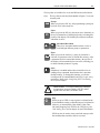
Throughout this manual we use notes to make you aware of safety
considerations:
!
ATTENTION: Identifies information about practices
or circumstances that can lead to personal injury or
death, property damage or economic loss.
Attention statements help you to:
• identify a hazard
• avoid the hazard
• recognize the consequences
Important: Identifies information that is critical for successful
application and understanding of the product.
GML, IMC, Flex I/O, PanelView, Data Highway Plus, SCANport, SLC, SLC 5/03, SLC 5/04, and SLC 5/05 are trademarks of
Allen-Bradley Company, Inc.
PLC is a registered trademark of Allen-Bradley Company, Inc.
Table of Contents
Preface
Who Should Use this Manual . . . . . . . . . . . . . . . . . . . . . . . . . . . . . . . . . . .P-1
Purpose of this Manual . . . . . . . . . . . . . . . . . . . . . . . . . . . . . . . . . . . . . . . .P-1
Contents of this Manual . . . . . . . . . . . . . . . . . . . . . . . . . . . . . . . . . . . . . . .P-2
Related Documentation . . . . . . . . . . . . . . . . . . . . . . . . . . . . . . . . . . . . . . .P-3
Conventions Used in this Manual . . . . . . . . . . . . . . . . . . . . . . . . . . . . . . . .P-3
Module Series Designator . . . . . . . . . . . . . . . . . . . . . . . . . . . . . . . . . . . . .P-3
1394 Product Receiving and Storage Responsibility . . . . . . . . . . . . . . . . .P-4
Allen-Bradley Support. . . . . . . . . . . . . . . . . . . . . . . . . . . . . . . . . . . . . . . . .P-4
Local Product Support . . . . . . . . . . . . . . . . . . . . . . . . . . . . . . . . . . . . . .P-4
Technical Product Assistance . . . . . . . . . . . . . . . . . . . . . . . . . . . . . . . .P-4
Chapter 1
Overview
The 1394 System . . . . . . . . . . . . . . . . . . . . . . . . . . . . . . . . . . . . . . . . . . . .1-1
Series Note . . . . . . . . . . . . . . . . . . . . . . . . . . . . . . . . . . . . . . . . . . . . . .1-1
Safety Precautions . . . . . . . . . . . . . . . . . . . . . . . . . . . . . . . . . . . . . . . . . . .1-2
1394 System Overview . . . . . . . . . . . . . . . . . . . . . . . . . . . . . . . . . . . . . . . .1-3
GMC System . . . . . . . . . . . . . . . . . . . . . . . . . . . . . . . . . . . . . . . . . . . . .1-3
CNC Interface System . . . . . . . . . . . . . . . . . . . . . . . . . . . . . . . . . . . . . .1-5
SERCOS System . . . . . . . . . . . . . . . . . . . . . . . . . . . . . . . . . . . . . . . . .1-6
Analog Servo System . . . . . . . . . . . . . . . . . . . . . . . . . . . . . . . . . . . . . .1-7
9/440 CNC System . . . . . . . . . . . . . . . . . . . . . . . . . . . . . . . . . . . . . . . .1-8
What is a 1394 System?. . . . . . . . . . . . . . . . . . . . . . . . . . . . . . . . . . . . . . .1-9
System Modules . . . . . . . . . . . . . . . . . . . . . . . . . . . . . . . . . . . . . . . . .1-10
Axis Modules . . . . . . . . . . . . . . . . . . . . . . . . . . . . . . . . . . . . . . . . . . . .1-11
External Shunt Module (used with 22 kW System) . . . . . . . . . . . . . . . 1-11
1326AB Motors . . . . . . . . . . . . . . . . . . . . . . . . . . . . . . . . . . . . . . . . . .1-12
1326AS Motors . . . . . . . . . . . . . . . . . . . . . . . . . . . . . . . . . . . . . . . . . .1-12
1326AH Motors . . . . . . . . . . . . . . . . . . . . . . . . . . . . . . . . . . . . . . . . . .1-13
Drive Interface Module . . . . . . . . . . . . . . . . . . . . . . . . . . . . . . . . . . . . .1-14
DC Link Module . . . . . . . . . . . . . . . . . . . . . . . . . . . . . . . . . . . . . . . . . .1-14
Standard Features of the 1394 . . . . . . . . . . . . . . . . . . . . . . . . . . . . . .1-15
Control . . . . . . . . . . . . . . . . . . . . . . . . . . . . . . . . . . . . . . . . . . . . . . .1-15
Power . . . . . . . . . . . . . . . . . . . . . . . . . . . . . . . . . . . . . . . . . . . . . . .1-16
Integration . . . . . . . . . . . . . . . . . . . . . . . . . . . . . . . . . . . . . . . . . . . .1-16
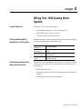
Chapter 2
Installing Your 1394
(applies to all systems)
Chapter Objectives . . . . . . . . . . . . . . . . . . . . . . . . . . . . . . . . . . . . . . . . . . .2-1
Complying With European Union Directives . . . . . . . . . . . . . . . . . . . . . . . .2-1
EMC Directive . . . . . . . . . . . . . . . . . . . . . . . . . . . . . . . . . . . . . . . . . . . .2-1
Low Voltage Directive . . . . . . . . . . . . . . . . . . . . . . . . . . . . . . . . . . . . . .2-2
Before Mounting Your System. . . . . . . . . . . . . . . . . . . . . . . . . . . . . . . . . . .2-2
Storing Your 1394 Before Installation . . . . . . . . . . . . . . . . . . . . . . . . . .2-2
Unpacking Modules . . . . . . . . . . . . . . . . . . . . . . . . . . . . . . . . . . . . . . . . . .2-3
System Mounting Requirements. . . . . . . . . . . . . . . . . . . . . . . . . . . . . . . . .2-3
Determining Your System Mounting Hole Layout . . . . . . . . . . . . . . . . .2-4
Mounting Your 1394 Through the Back of the Cabinet . . . . . . . . . . . . . 2-6
Bonding Your System . . . . . . . . . . . . . . . . . . . . . . . . . . . . . . . . . . . . . . . . .2-6
Bonding Modules . . . . . . . . . . . . . . . . . . . . . . . . . . . . . . . . . . . . . . . . . .2-6
Bonding Multiple Subpanels . . . . . . . . . . . . . . . . . . . . . . . . . . . . . . . . .2-8
Publication 1394-5.0 — May 2000
ii
Table of Contents
Mounting Your 1394 System . . . . . . . . . . . . . . . . . . . . . . . . . . . . . . . . . . . 2-8
Mounting Your 1394-DCLM . . . . . . . . . . . . . . . . . . . . . . . . . . . . . . . . . . . 2-11
Mounting the External Shunt Resistor for 5 and 10 kW System Modules 2-11
Mounting External Shunt Modules for 22 kW System Modules . . . . . . . . 2-11
Shunt Module Mounting Orientation . . . . . . . . . . . . . . . . . . . . . . . . . . 2-12
Shunt Module Mounted Outside the Cabinet . . . . . . . . . . . . . . . . . . . 2-13
Shunt Module Mounted Inside the Cabinet . . . . . . . . . . . . . . . . . . . . . 2-14
Mounting the Shunt Module. . . . . . . . . . . . . . . . . . . . . . . . . . . . . . . . . 2-15
Mounting Considerations for GMC and GMC Turbo Systems . . . . . . . . . 2-16
Mounting GMC and GMC Turbo Systems Next to Flex I/O . . . . . . . . . 2-16
Chapter 3
Wiring System, Axis, and Shunt
Modules, and Motors
(for all systems)
Publication 1394-5.0 — May 2000
Chapter Objectives. . . . . . . . . . . . . . . . . . . . . . . . . . . . . . . . . . . . . . . . . . . 3-1
Finding Additional Wiring Information for 1394 Systems . . . . . . . . . . . . . . 3-1
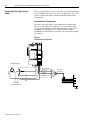
Understanding Basic Wiring Requirements . . . . . . . . . . . . . . . . . . . . . . . . 3-2
Routing High and Low Voltage Cables . . . . . . . . . . . . . . . . . . . . . . . . . 3-3
System Module Wire Sizes . . . . . . . . . . . . . . . . . . . . . . . . . . . . . . . . . . 3-4
Shielding . . . . . . . . . . . . . . . . . . . . . . . . . . . . . . . . . . . . . . . . . . . . . . . . 3-4
EMI/RFI Shielding . . . . . . . . . . . . . . . . . . . . . . . . . . . . . . . . . . . . . . . . . 3-4
EMI/RFI Bonding . . . . . . . . . . . . . . . . . . . . . . . . . . . . . . . . . . . . . . . . . 3-4
Input Power Conditioning . . . . . . . . . . . . . . . . . . . . . . . . . . . . . . . . . . . 3-5
Determining Your Type of Input Power . . . . . . . . . . . . . . . . . . . . . . . . . . . . 3-6
Grounded Power Configuration . . . . . . . . . . . . . . . . . . . . . . . . . . . . . . . 3-6
Ungrounded Power Configuration . . . . . . . . . . . . . . . . . . . . . . . . . . . . . 3-7
Setting the Ground Jumper in a 5 or 10 kW System Module for
Ungrounded Power Configurations . . . . . . . . . . . . . . . . . . . . . . . . . 3-8
Setting the Ground Jumper in a 22 kW System Module for
Ungrounded Power Configurations . . . . . . . . . . . . . . . . . . . . . . . . . 3-9
Grounding Your 1394 System . . . . . . . . . . . . . . . . . . . . . . . . . . . . . . . . . 3-12
Grounding your System to the Subpanel . . . . . . . . . . . . . . . . . . . . . . 3-12
Grounding Multiple Subpanels . . . . . . . . . . . . . . . . . . . . . . . . . . . . . . 3-13
Wiring System Module Power . . . . . . . . . . . . . . . . . . . . . . . . . . . . . . . . . 3-13
Terminal Block Locations for 5 and 10 kW System Module
(Series A and B) . . . . . . . . . . . . . . . . . . . . . . . . . . . . . . . . . . . . . . . . . 3-14
Connector Locations for 5 and 10 kW System Module (Series C) . . . 3-15
Terminal Block Locations for a 22 kW System Module . . . . . . . . . . . . 3-16
Required Tools and Equipment . . . . . . . . . . . . . . . . . . . . . . . . . . . . . . 3-17
Connecting Power Wiring for 5 and 10 kW (Series A and B)
and 22 kW System Modules . . . . . . . . . . . . . . . . . . . . . . . . . . . . . 3-17
Connecting Power Wiring for 5 and 10 kW System Modules
(Series C) . . . . . . . . . . . . . . . . . . . . . . . . . . . . . . . . . . . . . . . . . . . . 3-18
Connecting Motor Power to Axis Modules . . . . . . . . . . . . . . . . . . . . . . . . 3-19
Connecting Thermal and Brake Leads to Axis Modules . . . . . . . . . . . 3-20
Required Tools and Equipment . . . . . . . . . . . . . . . . . . . . . . . . . . . . . . 3-20
Wiring Motor Power, Thermals and Brakes . . . . . . . . . . . . . . . . . . . . . 3-21
Connecting Feedback to System Modules. . . . . . . . . . . . . . . . . . . . . . . . 3-24
Connecting Your Motor Cables to Motors. . . . . . . . . . . . . . . . . . . . . . . . . 3-26
Connecting Your External Shunt Resistor . . . . . . . . . . . . . . . . . . . . . . . . 3-26
Connecting Your External Shunt Resistor (Series A and B) . . . . . . . . 3-27
Connecting Your External Shunt Resistor (Series C) . . . . . . . . . . . . . 3-28
Table of Contents
Connecting Your Shunt Module (required for 22 kW system) . . . . . . . . .
Required Tools and Equipment . . . . . . . . . . . . . . . . . . . . . . . . . . . . .
Wiring the Shunt Module Power . . . . . . . . . . . . . . . . . . . . . . . . . . . . .
Wiring Shunt Module Fan Power . . . . . . . . . . . . . . . . . . . . . . . . . . . .
iii
3-28
3-28
3-29
3-33
Chapter 4
Wiring 1394 GMC and GMC Turbo
Systems
Chapter Objectives . . . . . . . . . . . . . . . . . . . . . . . . . . . . . . . . . . . . . . . . . . 4-1
Finding Additional Wiring Information for 1394 Systems . . . . . . . . . . . . . . 4-1
Understanding GMC and GMC Turbo Wiring and Connections . . . . . . . . 4-1
Understanding Input Wiring Board Layout. . . . . . . . . . . . . . . . . . . . . . . . . 4-2
Using the Terminal Operating Tool to Insert Wires . . . . . . . . . . . . . . . . 4-4
Input Wiring Board Signal Descriptions . . . . . . . . . . . . . . . . . . . . . . . . 4-5
Connecting Your Communication Cables . . . . . . . . . . . . . . . . . . . . . . . . . 4-7
Encoder Feedback Wiring . . . . . . . . . . . . . . . . . . . . . . . . . . . . . . . . . 4-10
Serial Communications . . . . . . . . . . . . . . . . . . . . . . . . . . . . . . . . . . . 4-11
Data Highway Connection . . . . . . . . . . . . . . . . . . . . . . . . . . . . . . . . . 4-13
AxisLink . . . . . . . . . . . . . . . . . . . . . . . . . . . . . . . . . . . . . . . . . . . . . . . 4-14
GMC Turbo System . . . . . . . . . . . . . . . . . . . . . . . . . . . . . . . . . . . . . . 4-15
Remote I/O . . . . . . . . . . . . . . . . . . . . . . . . . . . . . . . . . . . . . . . . . . . . . 4-16
Flex I/O . . . . . . . . . . . . . . . . . . . . . . . . . . . . . . . . . . . . . . . . . . . . . . . . 4-16
SLC Interface . . . . . . . . . . . . . . . . . . . . . . . . . . . . . . . . . . . . . . . . . . . 4-17
Connecting a GMC and GMC Turbo to a 1394-DIM . . . . . . . . . . . . . . . . 4-19
1394-DIM System Example . . . . . . . . . . . . . . . . . . . . . . . . . . . . . . . . 4-19
1394-DIM with 1398-DDM-xxx System Example . . . . . . . . . . . . . . . . 4-20
1394-DIM Configurations . . . . . . . . . . . . . . . . . . . . . . . . . . . . . . . . . . 4-21
Configuration Examples . . . . . . . . . . . . . . . . . . . . . . . . . . . . . . . . . . . 4-22
1394-System Module Input Power Wiring When
Not Using Axis Modules . . . . . . . . . . . . . . . . . . . . . . . . . . . . . . . . . 4-24
Understanding DIM Signals . . . . . . . . . . . . . . . . . . . . . . . . . . . . . . . . . . . 4-24
DROK . . . . . . . . . . . . . . . . . . . . . . . . . . . . . . . . . . . . . . . . . . . . . . . . . 4-24
Drive Enable Output . . . . . . . . . . . . . . . . . . . . . . . . . . . . . . . . . . . . . . 4-25
Analog Output . . . . . . . . . . . . . . . . . . . . . . . . . . . . . . . . . . . . . . . . . . 4-25
Wiring and Configuring an External Drive to the 1394-DIM. . . . . . . . . . . 4-26
Connecting the Remote Drive to the DIM Connector . . . . . . . . . . . . . 4-26
Connecting the Position Feedback Encoder to the Feedback Input . . 4-29
Connecting the DIM Ground Wire to the 1394 System Ground . . . . . 4-30
Installing the Resolver Feedback Input Plug . . . . . . . . . . . . . . . . . . . 4-30
Chapter 5
Wiring Your 1394 Analog Servo System
Chapter Objectives . . . . . . . . . . . . . . . . . . . . . . . . . . . . . . . . . . . . . . . . . . 5-1
Finding Additional Wiring Information for 1394 Systems . . . . . . . . . . . . . . 5-1
Understanding Analog Servo Wiring and Connections . . . . . . . . . . . . . . . 5-1
Input Wiring Board Layout . . . . . . . . . . . . . . . . . . . . . . . . . . . . . . . . . . . . . 5-2
Using the Terminal Operating Tool to Insert Wires . . . . . . . . . . . . . . . . 5-2
Input Wiring Board Signal Descriptions . . . . . . . . . . . . . . . . . . . . . . . . 5-4
Connecting AQB and SCANport Cables . . . . . . . . . . . . . . . . . . . . . . . . . . 5-5
Analog Servo Encoder (A Quad B) Wiring . . . . . . . . . . . . . . . . . . . . . . 5-5
SCANport Adapter . . . . . . . . . . . . . . . . . . . . . . . . . . . . . . . . . . . . . . . . 5-7
Publication 1394-5.0 — May 2000
iv
Table of Contents
Chapter 6
Commissioning 1394 GMC and GMC
Turbo Systems
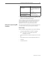
Chapter Objectives. . . . . . . . . . . . . . . . . . . . . . . . . . . . . . . . . . . . . . . . . . . 6-1
General Startup Precautions . . . . . . . . . . . . . . . . . . . . . . . . . . . . . . . . . . . 6-1
Applying Power to the System . . . . . . . . . . . . . . . . . . . . . . . . . . . . . . . . . . 6-2
Setting Up Your System Using GML Commander . . . . . . . . . . . . . . . . . . . 6-3
Before You Begin . . . . . . . . . . . . . . . . . . . . . . . . . . . . . . . . . . . . . . . . . 6-3
Preparing the System . . . . . . . . . . . . . . . . . . . . . . . . . . . . . . . . . . . . . . 6-4
Setting Up Your System Using GML 3.x.x . . . . . . . . . . . . . . . . . . . . . . . . . 6-5
Before You Begin . . . . . . . . . . . . . . . . . . . . . . . . . . . . . . . . . . . . . . . . . 6-5
Preparing the System . . . . . . . . . . . . . . . . . . . . . . . . . . . . . . . . . . . . . . 6-5
Chapter 7
Commissioning Your 1394 Analog
Servo System
Chapter Objectives. . . . . . . . . . . . . . . . . . . . . . . . . . . . . . . . . . . . . . . . . . . 7-1
General Startup Precautions . . . . . . . . . . . . . . . . . . . . . . . . . . . . . . . . . . . 7-1
Setting Up Your 1394 Analog Servo System . . . . . . . . . . . . . . . . . . . . . . . 7-2
Before You Begin . . . . . . . . . . . . . . . . . . . . . . . . . . . . . . . . . . . . . . . . . 7-2
Exiting Before You’re Finished . . . . . . . . . . . . . . . . . . . . . . . . . . . . . 7-2
Continuing From Where You Left Off . . . . . . . . . . . . . . . . . . . . . . . . 7-2
Removing and Re-Applying Power . . . . . . . . . . . . . . . . . . . . . . . . . . . . 7-3
Setting Up at the System Level . . . . . . . . . . . . . . . . . . . . . . . . . . . . . . . 7-4
Setting Up Analog Test Points . . . . . . . . . . . . . . . . . . . . . . . . . . . . . . . . 7-5
Defining Your Motor . . . . . . . . . . . . . . . . . . . . . . . . . . . . . . . . . . . . . . . 7-5
Defining a Reference Source forYour Axes . . . . . . . . . . . . . . . . . . . . . 7-6
Defining Analog Velocity . . . . . . . . . . . . . . . . . . . . . . . . . . . . . . . . . . 7-7
Defining Analog Torque . . . . . . . . . . . . . . . . . . . . . . . . . . . . . . . . . . 7-8
Defining Digital Velocity . . . . . . . . . . . . . . . . . . . . . . . . . . . . . . . . . . 7-8
Defining Digital Torque . . . . . . . . . . . . . . . . . . . . . . . . . . . . . . . . . . . 7-9
Defining Limits . . . . . . . . . . . . . . . . . . . . . . . . . . . . . . . . . . . . . . . . . . 7-10
Auto Tuning . . . . . . . . . . . . . . . . . . . . . . . . . . . . . . . . . . . . . . . . . . . . . 7-11
Before You Perform an Auto Tune . . . . . . . . . . . . . . . . . . . . . . . . . . 7-11
Performing the Auto Tune . . . . . . . . . . . . . . . . . . . . . . . . . . . . . . . . 7-11
Chapter 8
Configuring Your 1394 Analog Servo
System
Chapter Objectives. . . . . . . . . . . . . . . . . . . . . . . . . . . . . . . . . . . . . . . . . . . 8-1
Where to Look for Other Programming Information . . . . . . . . . . . . . . . . . . 8-1
Conventions Used in this Chapter . . . . . . . . . . . . . . . . . . . . . . . . . . . . . . . 8-2
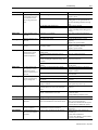
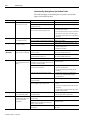
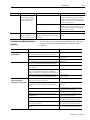
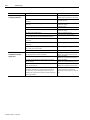
Understanding Analog Servo System Parameters. . . . . . . . . . . . . . . . . . . 8-3
1394 Analog Servo Software Diagrams . . . . . . . . . . . . . . . . . . . . . . . . . . 8-28
Chapter 9
Troubleshooting
Publication 1394-5.0 — May 2000
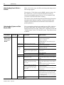
Chapter Objectives. . . . . . . . . . . . . . . . . . . . . . . . . . . . . . . . . . . . . . . . . . . 9-1
Understanding How to Detect a Problem. . . . . . . . . . . . . . . . . . . . . . . . . . 9-2
Understanding System and Axis Module LEDs . . . . . . . . . . . . . . . . . . . . . 9-2
Understanding System Faults . . . . . . . . . . . . . . . . . . . . . . . . . . . . . . . . . . 9-5
Finding GMC Faults . . . . . . . . . . . . . . . . . . . . . . . . . . . . . . . . . . . . . . . 9-5
Viewing Instantaneous Status . . . . . . . . . . . . . . . . . . . . . . . . . . . . . 9-5
Viewing Continuous Status . . . . . . . . . . . . . . . . . . . . . . . . . . . . . . . . 9-6
Finding Analog Servo System Faults . . . . . . . . . . . . . . . . . . . . . . . . . . 9-7
Table of Contents
v
Finding 9/440 Faults . . . . . . . . . . . . . . . . . . . . . . . . . . . . . . . . . . . . . . . 9-7
Finding CNC Interface Faults . . . . . . . . . . . . . . . . . . . . . . . . . . . . . . . . 9-8
Understanding GMC Turbo and GMC Controller Faults. . . . . . . . . . . . . . . 9-9
Understanding Analog Servo System Module Faults . . . . . . . . . . . . . . . 9-10
Understanding Analog Servo System Axis Faults . . . . . . . . . . . . . . . 9-12
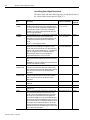
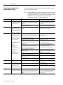
Troubleshooting General System Problems. . . . . . . . . . . . . . . . . . . . . . . 9-13
Replacing System and Axis Modules . . . . . . . . . . . . . . . . . . . . . . . . . . . 9-16
Before You Begin . . . . . . . . . . . . . . . . . . . . . . . . . . . . . . . . . . . . . . . . 9-16
Removing an Axis Module . . . . . . . . . . . . . . . . . . . . . . . . . . . . . . . . . 9-17
Installing a Replacement Axis Module . . . . . . . . . . . . . . . . . . . . . . . . 9-18
Removing a System Module . . . . . . . . . . . . . . . . . . . . . . . . . . . . . . . 9-19
Installing a Replacement System Module . . . . . . . . . . . . . . . . . . . . . 9-20
Replacing System Modules of the Same Series . . . . . . . . . . . . . . 9-22
Replacing System Modules of a Different Series . . . . . . . . . . . . . . 9-22
Completing Connections and Downloading Parameters . . . . . . . . 9-22
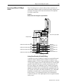
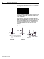
Checking for a Blown Fuse in the 1394-DCLM . . . . . . . . . . . . . . . . . . . . 9-23
Replacing the 1394 Shunt Module Fuse . . . . . . . . . . . . . . . . . . . . . . . . . 9-25
Replacing the 1394-SR10A Fuse . . . . . . . . . . . . . . . . . . . . . . . . . . . . 9-25
Replacing the 1394-SR9A, -SR9AF, -SR36A, and -SR36AF Fuse . . 9-26
Replacing the AM50 and AM75 Axis Module Fan . . . . . . . . . . . . . . . . . . 9-28
Removing the Fan . . . . . . . . . . . . . . . . . . . . . . . . . . . . . . . . . . . . . . . 9-28
Installing the New Fan . . . . . . . . . . . . . . . . . . . . . . . . . . . . . . . . . . . . 9-31
Appendix A
Specifications
Chapter Objectives . . . . . . . . . . . . . . . . . . . . . . . . . . . . . . . . . . . . . . . . . . A-1
System Specifications . . . . . . . . . . . . . . . . . . . . . . . . . . . . . . . . . . . . . . . . A-1
Certification . . . . . . . . . . . . . . . . . . . . . . . . . . . . . . . . . . . . . . . . . . . . . A-1
System Modules . . . . . . . . . . . . . . . . . . . . . . . . . . . . . . . . . . . . . . . . . . A-2
Axis Modules . . . . . . . . . . . . . . . . . . . . . . . . . . . . . . . . . . . . . . . . . . . . A-3
Contact Ratings . . . . . . . . . . . . . . . . . . . . . . . . . . . . . . . . . . . . . . . . . . A-3
DC Link Module . . . . . . . . . . . . . . . . . . . . . . . . . . . . . . . . . . . . . . . . . . A-4
Drive Interface Module . . . . . . . . . . . . . . . . . . . . . . . . . . . . . . . . . . . . . A-4
Filters . . . . . . . . . . . . . . . . . . . . . . . . . . . . . . . . . . . . . . . . . . . . . . . . . . A-4
User-Supplied Contactor (M1) . . . . . . . . . . . . . . . . . . . . . . . . . . . . . . . A-5
User-Supplied Line Input Fusing . . . . . . . . . . . . . . . . . . . . . . . . . . . . . A-5
User-Supplied 24V Logic Input Power . . . . . . . . . . . . . . . . . . . . . . . . . A-5
Input Transformer for 24V Control Power . . . . . . . . . . . . . . . . . . . . . . . A-6
User-Supplied 5V Auxiliary Encoder Power Supply . . . . . . . . . . . . . . . A-6
Circuit Breakers . . . . . . . . . . . . . . . . . . . . . . . . . . . . . . . . . . . . . . . . . . A-6
External Shunt Resistor Kit for 5 and 10 kW Systems . . . . . . . . . . . . . A-8
1394 Shunt Module for the 22 kW System . . . . . . . . . . . . . . . . . . . . . . A-8
Environmental Specifications. . . . . . . . . . . . . . . . . . . . . . . . . . . . . . . . . . . A-9
Power Dissipation . . . . . . . . . . . . . . . . . . . . . . . . . . . . . . . . . . . . . . . . . . A-10
System Modules . . . . . . . . . . . . . . . . . . . . . . . . . . . . . . . . . . . . . . . . . A-10
Axis Modules . . . . . . . . . . . . . . . . . . . . . . . . . . . . . . . . . . . . . . . . . . . A-10
DC Link Module . . . . . . . . . . . . . . . . . . . . . . . . . . . . . . . . . . . . . . . . . A-11
Drive Interface Module . . . . . . . . . . . . . . . . . . . . . . . . . . . . . . . . . . . . A-11
Internal Shunt Resistor for the 5 and 10 kW System (standard) . . . . A-11
Communication Specifications. . . . . . . . . . . . . . . . . . . . . . . . . . . . . . . . . A-11
Encoder Input Specifications . . . . . . . . . . . . . . . . . . . . . . . . . . . . . . . A-11
Publication 1394-5.0 — May 2000
vi
Table of Contents
Dedicated Discrete I/O Specifications . . . . . . . . . . . . . . . . . . . . . . . . A-12
Serial I/O Specifications . . . . . . . . . . . . . . . . . . . . . . . . . . . . . . . . . . . A-12
DH-485 Specifications . . . . . . . . . . . . . . . . . . . . . . . . . . . . . . . . . . . . A-13
Flex I/O Specifications . . . . . . . . . . . . . . . . . . . . . . . . . . . . . . . . . . . . A-13
GMC System Specifications . . . . . . . . . . . . . . . . . . . . . . . . . . . . . . . . A-14
Remote I/O Adapter Specifications . . . . . . . . . . . . . . . . . . . . . . . . . . . A-15
AxisLink Specifications . . . . . . . . . . . . . . . . . . . . . . . . . . . . . . . . . . . . A-16
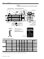
Dimensions . . . . . . . . . . . . . . . . . . . . . . . . . . . . . . . . . . . . . . . . . . . . . . . A-17
1394 System Module Dimensions . . . . . . . . . . . . . . . . . . . . . . . . . . . A-17
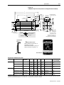
Axis Module Dimensions . . . . . . . . . . . . . . . . . . . . . . . . . . . . . . . . . . A-18
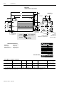
Filter Dimensions . . . . . . . . . . . . . . . . . . . . . . . . . . . . . . . . . . . . . . . . A-20
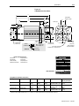
External Shunt Dimensions . . . . . . . . . . . . . . . . . . . . . . . . . . . . . . . . A-22
Motor Dimensions . . . . . . . . . . . . . . . . . . . . . . . . . . . . . . . . . . . . . . . . A-25
Servo Motor Performance Data . . . . . . . . . . . . . . . . . . . . . . . . . . . . . . . . A-32
1326AB Performance Data . . . . . . . . . . . . . . . . . . . . . . . . . . . . . . . . . A-32
1326AS Performance Data . . . . . . . . . . . . . . . . . . . . . . . . . . . . . . . . . A-33
Appendix B
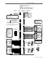
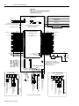
Interconnect and CE Diagrams
Chapter Objectives. . . . . . . . . . . . . . . . . . . . . . . . . . . . . . . . . . . . . . . . . . . B-1
GMC, Analog Servo, and CNC Interface Interconnect Diagrams. . . . . . . . B-2
1394 GMC Interconnections . . . . . . . . . . . . . . . . . . . . . . . . . . . . . . . . . B-3
1394 Analog Servo Interconnections . . . . . . . . . . . . . . . . . . . . . . . . . . B-9
1394 CNC Interconnections . . . . . . . . . . . . . . . . . . . . . . . . . . . . . . . . B-12
Thermal Interconnect Diagrams. . . . . . . . . . . . . . . . . . . . . . . . . . . . . . . . B-14
1394 GMC Systems (1394x-SJTxx-C and -T) . . . . . . . . . . . . . . . . . . B-15
1394 GMC Systems (1394C-SJTxx-L) . . . . . . . . . . . . . . . . . . . . . . . . B-19
1394 Analog Servo Systems (1394x-SJTxx-A) . . . . . . . . . . . . . . . . . B-21
Cable Pin-outs . . . . . . . . . . . . . . . . . . . . . . . . . . . . . . . . . . . . . . . . . . . . . B-23
1326 Cable Pin-outs . . . . . . . . . . . . . . . . . . . . . . . . . . . . . . . . . . . . . . B-23
1394 Cable Pin-outs . . . . . . . . . . . . . . . . . . . . . . . . . . . . . . . . . . . . . . B-26
Grounding for 1394 CE Requirements . . . . . . . . . . . . . . . . . . . . . . . . B-30
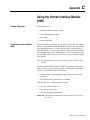
Appendix C
Using the Human Interface Module
(HIM)
Publication 1394-5.0 — May 2000
Chapter Objectives. . . . . . . . . . . . . . . . . . . . . . . . . . . . . . . . . . . . . . . . . . . C-1
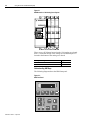
The Human Interface Module (HIM). . . . . . . . . . . . . . . . . . . . . . . . . . . . . . C-1
Understanding HIM Keys . . . . . . . . . . . . . . . . . . . . . . . . . . . . . . . . . . . C-2
Understanding HIM Operation . . . . . . . . . . . . . . . . . . . . . . . . . . . . . . . . . . C-4
Understanding HIM Modes . . . . . . . . . . . . . . . . . . . . . . . . . . . . . . . . . . C-5
Display Mode . . . . . . . . . . . . . . . . . . . . . . . . . . . . . . . . . . . . . . . . . . C-5
Program Mode . . . . . . . . . . . . . . . . . . . . . . . . . . . . . . . . . . . . . . . . .C-5
Link Mode . . . . . . . . . . . . . . . . . . . . . . . . . . . . . . . . . . . . . . . . . . . . .C-5
Startup Mode . . . . . . . . . . . . . . . . . . . . . . . . . . . . . . . . . . . . . . . . . . C-5
EEProm Mode . . . . . . . . . . . . . . . . . . . . . . . . . . . . . . . . . . . . . . . . .C-5
Search Mode . . . . . . . . . . . . . . . . . . . . . . . . . . . . . . . . . . . . . . . . . . C-6
Control Status Mode . . . . . . . . . . . . . . . . . . . . . . . . . . . . . . . . . . . . .C-6
Password . . . . . . . . . . . . . . . . . . . . . . . . . . . . . . . . . . . . . . . . . . . . .C-6
Linking Parameters . . . . . . . . . . . . . . . . . . . . . . . . . . . . . . . . . . . . . . . .C-6
Using Copy Cat . . . . . . . . . . . . . . . . . . . . . . . . . . . . . . . . . . . . . . . . . . . C-7
Copying a System’s Information . . . . . . . . . . . . . . . . . . . . . . . . . . . . C-8
Table of Contents
vii
Pasting a System’s Information . . . . . . . . . . . . . . . . . . . . . . . . . . . . C-9
Auto Tuning . . . . . . . . . . . . . . . . . . . . . . . . . . . . . . . . . . . . . . . . . . . . . . . C-10
Getting an Overview of HIM Programming . . . . . . . . . . . . . . . . . . . . . C-11
Removing the HIM . . . . . . . . . . . . . . . . . . . . . . . . . . . . . . . . . . . . . . . . . . C-14
Removing the HIM from the HIM Cradle . . . . . . . . . . . . . . . . . . . . . . C-14
Disconnecting the HIM from the System Module . . . . . . . . . . . . . . . . C-14
Setting Up the HIM for Hand-Held Use . . . . . . . . . . . . . . . . . . . . . . . C-15
Placing the HIM in the HIM Cradle . . . . . . . . . . . . . . . . . . . . . . . . . . . C-16
Appendix D
Catalog Numbers
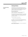
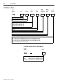
Understanding Catalog Numbers . . . . . . . . . . . . . . . . . . . . . . . . . . . . . . . D-1
Determining Catalog Numbers . . . . . . . . . . . . . . . . . . . . . . . . . . . . . . . D-1
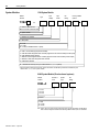
System Modules . . . . . . . . . . . . . . . . . . . . . . . . . . . . . . . . . . . . . . . . . . . . D-2
1394 System Module . . . . . . . . . . . . . . . . . . . . . . . . . . . . . . . . . . . . . . D-2
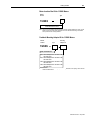
9/440 System Module (Resolver based systems) . . . . . . . . . . . . . . . . D-2
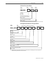
CNC Serial Drive System Module . . . . . . . . . . . . . . . . . . . . . . . . . . . . D-3
9/440 High Resolution/Absolute CNC System Module . . . . . . . . . . . . D-3
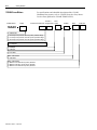
Axis Modules . . . . . . . . . . . . . . . . . . . . . . . . . . . . . . . . . . . . . . . . . . . . . . D-4
External Shunt Modules . . . . . . . . . . . . . . . . . . . . . . . . . . . . . . . . . . . . . . D-4
Shunt Resistor Kit for 5 and 10 kW System Modules . . . . . . . . . . . . . . D-4
Shunt Modules for 22 kW System Modules . . . . . . . . . . . . . . . . . . . . . D-4
System Module Cables . . . . . . . . . . . . . . . . . . . . . . . . . . . . . . . . . . . . . . . D-5
Control Interface Cables . . . . . . . . . . . . . . . . . . . . . . . . . . . . . . . . . . . . D-5
Single Axis Flying Lead Cable . . . . . . . . . . . . . . . . . . . . . . . . . . . . . . . D-5
Two-Axis Prewired Cable . . . . . . . . . . . . . . . . . . . . . . . . . . . . . . . . . . . D-5
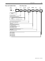
1326AB Servo Motors . . . . . . . . . . . . . . . . . . . . . . . . . . . . . . . . . . . . . . . . D-6
1326 Shaft Oil Seal Kit for 1326AB Motors . . . . . . . . . . . . . . . . . . . . . D-6
Motor Junction Box Kit for 1326AB Motors . . . . . . . . . . . . . . . . . . . . . . D-7
Feedback Mounting Adapter Kit for 1326AB Motors . . . . . . . . . . . . . . D-7
1326AS Servo Motors . . . . . . . . . . . . . . . . . . . . . . . . . . . . . . . . . . . . . . . . D-8
1326 Shaft Oil Seal Kit for 1326AS Motors . . . . . . . . . . . . . . . . . . . . . D-8
Motor Junction Box Kit for 1326AS Motors . . . . . . . . . . . . . . . . . . . . . . D-9
Feedback Mounting Adapter Kit for 1326AS Motors . . . . . . . . . . . . . . D-9
1326AH Servo Motors . . . . . . . . . . . . . . . . . . . . . . . . . . . . . . . . . . . . . . . D-10
Power and Feedback Cables . . . . . . . . . . . . . . . . . . . . . . . . . . . . . . . . . . D-11
Motor Power Cables . . . . . . . . . . . . . . . . . . . . . . . . . . . . . . . . . . . . . . D-11
Motor Feedback Cables . . . . . . . . . . . . . . . . . . . . . . . . . . . . . . . . . . . D-12
Encoder Feedback Cables for 1326AB Motors . . . . . . . . . . . . . . . . . D-12
Miscellaneous Accessories . . . . . . . . . . . . . . . . . . . . . . . . . . . . . . . . . . . D-13
Publication 1394-5.0 — May 2000
viii
Table of Contents
Publication 1394-5.0 — May 2000
Preface
Read this preface to familiarize yourself with the rest of the manual. This
preface covers the following topics:
Who Should Use this Manual
•
Who should use this manual
•
The purpose of this manual
•
Contents of this manual
•
Related documentation
•
Conventions used in this manual
•
1394 product receiving and storage responsibility
•
Allen-Bradley support
Use this manual if you are responsible for designing, installing,
programming, or troubleshooting the Allen-Bradley 1394 family of
products.
If you do not have a basic understanding of the 1394, contact your local
Allen-Bradley representative for information on available training courses
before using this product.
Purpose of this Manual
This manual is a user guide for the 1394. It gives you an overview of the
1394 family and describes the procedures you use to install, set up, use,
and troubleshoot the 1394.
Publication 1394-5.0 — May 2000
P-2
Preface
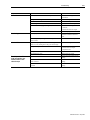
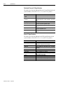
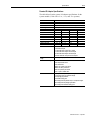
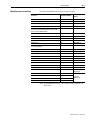
Contents of this Manual
Chapter
Title
Preface
1
Overview
2
Installing Your 1394
(applies to all systems)
Wiring System, Axis, and
Shunt Modules, and
Motors (for all systems)
Wiring 1394 GMC and
GMC Turbo Systems
Wiring Your 1394 Analog
Servo System
Commissioning 1394
GMC and GMC Turbo
Systems
Commissioning Your 1394
Analog Servo System
Configuring Your 1394
Analog Servo System
Troubleshooting
3
4
5
6
7
8
9
Appendix A
Appendix B
Appendix C
Appendix D
Publication 1394-5.0 — May 2000
Contents
Describes the purpose, background, and scope
of this manual. Also specifies the audience for
whom this manual is intended.
Explains and illustrates the theory behind the
1394’s operation. Covers hardware and software
features.
Provides mounting information for your 1394
system.
Provides information on how to connect your
1394 system components together.
Provides information on how to wire your 1394
GMC and GMC Turbo System Modules.
Provides information on how to wire your 1394
Analog Servo System Module.
Provides information about parameters used to
configure your 1394 GMC and GMC Turbo.
Provides information about parameters used to
configure your 1394 Analog Servo Module.
Provides supplemental information on using
communication tools.
Explains how to interpret and correct problems
with your 1394 system.
Specifications
Provides physical, electrical, environmental, and
functional specifications for the 1394.
Interconnect and CE
Provides diagrams showing the interconnections
Diagrams
for the available 1394 configurations and
installation requirements to meet CE directives.
Using the Human Interface Provides information that will help you to use the
Module (HIM)
HIM.
Catalog Numbers
Provides catalog number descriptions of 1394
and related products.
Preface
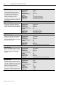
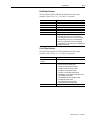
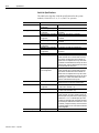
Related Documentation
P-3
The following documents contain additional information concerning
related Allen-Bradley products. To obtain a copy, contact your local
Allen-Bradley office or distributor.
For:
Read This Document:
Document Number:
A description and specifications for the 1394 family
1394 Digital, AC, Multi-Axis Motion Control
System Product Data
1394-2.0
A description and specifications for the 1326ATorque Plus
Motors used with the 1394
1326AB 460V, Torque Plus Series, AC Servo
Motors Product Data
1326A-2.9
A description and specifications for the 1326A Rare Earth
Motors used with the 1394
1326AS Series 460V, Lo w Inertia, Brushless
Servo Motors Product Data
1326A-2.10
Product information regarding cables used with the 1326AB and 1326 Cables for 460V AC Servo Motors
1326AS motors
1326A-2.11
A user guide for GML programming to be used with the 1394
GMC System.
GMLC-5.2
GML Commander Reference Manual
An overview of the Flex I/O products
Flex I/O Product Profile
1794-1.14
Specifications for the Flex I/O products
Flex I/O Product Data
1794-2.1
An overview of the PanelView 550/600 product
PanelView 550/600 Product Profile
2711-1.13
An overview of the 9/Series products
9/Series CNC Product Profile
8520-1.3
A manual that provides you information on RIO communications Installation Guidelines for the Twinaxial Cable
92-D1770-BCO
A manual that assists you with integrating and maintaining the
9/Series to be used with the 1394 CNC Interface System
9/Series Integration and Maintenance Manual 8520-6.2
An article on wire sizes and types for grounding electrical
equipment
National Electrical Code
Published by the National Fire
Protection Association of Boston, MA.
A glossary of industrial automation terms and abbreviations
Allen-Bradley Industrial Automation Glossary
AG-7.1
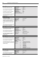
Conventions Used in this Manual
Module Series Designator
The following conventions are used throughout this manual:
•
Bulleted lists such as this one provide information, not procedural
steps.
•
Numbered lists provide sequential steps or hierarchical
information.
•
Words that you type or select appear in bold.
•
When we refer you to another location, the section or chapter
name appears in italics.
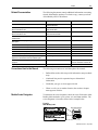
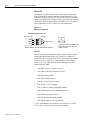
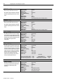
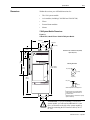
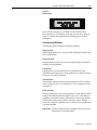
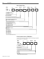
To determine the series designator, check the series field on the AllenBradley label attached to your system, axis, and shunt modules. The
series designator is located as shown in the example below.
Figure P.1
Allen-Bradley Label
ALLEN-BRADLEY
Shunt Module Example
R
BULLETIN 1394 300W SHUNT MODULE
CAT.
PART
SER.
INPUT DC
INPUT AC
FOR FUSE REPLACEMENT USE:
BUSSMAN CAT. NO.
FOR USE WITH 1394-SJT22-X SYSTEM MODULE
1394 Digital Servo Controller
300W Shunt Module
ALLEN-BRADLEY
Series Field
R
BULLETIN 1394 300W SHUNT MODULE
CAT.
PART
SER.
INPUT DC
INPUT AC
FOR FUSE REPLACEMENT USE:
BUSSMAN CAT. NO.
FOR USE WITH 1394-SJT22-X SYSTEM MODULE
Publication 1394-5.0 — May 2000
P-4
Preface
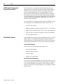
1394 Product Receiving and
Storage Responsibility
You, the customer, are responsible for thoroughly inspecting the
equipment before accepting the shipment from the freight company.
Check the item(s) you receive against your purchase order. If any
items are obviously damaged, it is your responsibility to refuse
delivery until the freight agent has noted the damage on the freight
bill. Should you discover any concealed damage during unpacking,
you are responsible for notifying the freight agent. Leave the shipping
container intact and request that the freight agent make a visual
inspection of the equipment.
Leave the product in its shipping container prior to installation. If you
are not going to use the equipment for a period of time, store it:
Allen-Bradley Support
•
in a clean, dry location
•
within an ambient temperature range of 0 to 65° C (32 to 149° F)
•
within a relative humidity range of 5% to 95%, non-condensing
•
in an area where it cannot be exposed to a corrosive atmosphere
•
in a non-construction area
Allen-Bradley offers support services worldwide, with over 75 Sales/
Support Offices, 512 authorized Distributors and 260 authorized
Systems Integrators located throughout the United States alone, plus
Allen-Bradley representatives in every major country in the world.
Local Product Support
Contact your local Allen-Bradley representative for:
•
sales and order support
•
product technical training
•
warranty support
•
support service agreements
Technical Product Assistance
If you need to contact Allen-Bradley for technical assistance, please
review the information in the Troubleshooting chapter first. Then call
your local Allen-Bradley representative. For the quickest possible
response, please have the catalog numbers of your products available
when you call.
Publication 1394-5.0 — May 2000
Chapter
1
Overview
The 1394 System
The 1394 is a modular, multi-axis motion control and drive system
family. Its unique design allows the 1394 to be used as an integrated
motion controller and drive system (GMC) with Turbo or standard
IMC S Class Compact functionality, an integrated 9/440 CNC
system, a 9/Series CNC digital interface drive system, a SERCOS
servo drive system, or an analog servo drive system.
All 1394 systems provide direct line connection (transformerless) for
360 and 480V three-phase input power, efficient IGBT power
conversion, and slide-and-lock, module-to-module connection
systems. Each system module can be configured with up to four axis
modules, with each axis module interfacing to a motor. The 1394
provides significant panel space and interconnect savings.
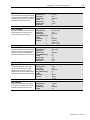
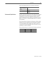
Series Note
Series C system modules (catalog numbers 1394C-SJTxx-x) and axis
modules (catalog numbers 1394C-AMxx and -AMxx-IH) include
features not available on Series A and B modules (catalog numbers
1394-SJTxx-x and 1394-AMxx).
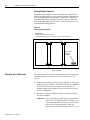
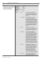
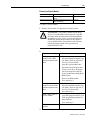
Feature Availability
System Module Features:
Series C
Series A and B
Connector (plug-in) input power termination
Yes
No
Cable Clamp (strain relief, shield bond)
Yes
No
EMI filter (24V input power, registration)
Yes
No
Smart Power (Soft Start, power monitor)
Yes
22 kW systems only
Feature Availability
Axis Module Features:
Series C
Series A and B
Cable Clamp (strain relief, shield bond)
Yes
No
EMI filter (motor brake and thermal circuit)
Yes
No
Series C system modules are interchangeable with Series A and B.
Likewise, Series A, B, and C axis modules are interchangeable with
each other.
Series C is recommended for all new applications. See the tables
above for feature availability. For help in determining the series of
your module(s), refer to the section Module Series Designator in the
Preface.
Publication 1394-5.0 — May 2000
1-2
Overview
Safety Precautions
The following general precautions apply to the 1394:
!
ATTENTION: Only those familiar with the 1394
Digital, AC, Multi-Axis Motion Control System and
associated machinery should plan or implement the
installation, startup, and subsequent maintenance of
the system. Failure to comply can result in personal
injury and/or equipment damage.
ATTENTION: This product contains stored energy
devices. To avoid hazard of electrical shock, wait five
minutes after removing power or verify that all voltage
on the capacitors has been discharged before
attempting to service, repair, or remove this unit.You
should only attempt the procedures in this manual if
you are qualified to do so and familiar with solid-state
control equipment and the safety procedures in
publication NFPA 70E.
ATTENTION: The system integrator is responsible
for local safety and electrical codes.
!
ATTENTION: An incorrectly applied or installed
drive can result in component damage or a reduction
in product life. Wiring or application errors, such as
undersizing the motor, incorrect or inadequate AC
supply, or excessive ambient temperatures can result
in malfunction of the drive.
ATTENTION: This drive contains ESD
(Electrostatic Discharge) sensitive parts and
assemblies. Static control precautions are required
when installing, testing, servicing, or repairing this
assembly. Component damage can result if ESD
control procedures are not followed. If you are not
familiar with static control procedures, refer to AllenBradley publication 8000-4.5.2, Guarding Against
Electrostatic Damage or any other applicable ESD
Protection Handbook.
Publication 1394-5.0 — May 2000
Overview
1394 System Overview
1-3
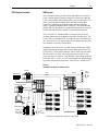
GMC System
The 1394 GMC System provides all the functionality of the IMC S
Class Compact Motion Controller and power conversion within the
1394 system module. Allen-Bradley offers two versions of the 1394
GMC system module (Standard GMC and GMC Turbo). Both
systems are completely programmed and commissioned using
GML (Graphical Motion Control Language), offer Allen-Bradley
DH485, RS-232, and RS-422 as standard communications, and have
Remote I/O and AxisLink available as communication options.
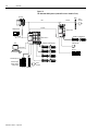
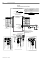
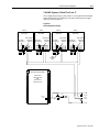
The 1394x-SJTxx-C (Standard GMC) system supports four axis
modules and provides four channels of auxiliary encoder input. The
1394C-SJTxx-L (Standard GMC) provides the same functionality of
the 1394x-SJTxx-C, but supports only one axis module and provides
two channels of auxiliary encoder input.
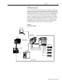
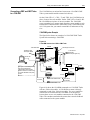
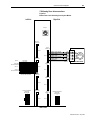
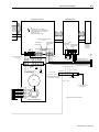
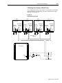
In addition, the 1394x-SJTxx-T (GMC Turbo) provides more GML
application program memory and executes the programs faster. The
1394x-SJTxx-T offers 64K of memory with a 32-bit processor while
the 1394x-SJTxx-C offers 32K of program memory with a 16-bit
processor. The 1394x-SJTxx-T also includes a direct, high speed link
to the SLC 5/03, 5/04, or 5/05 that simplifies the programming
required to transfer data between the 1394x-SJTxx-T and the SLC.
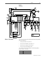
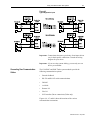
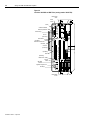
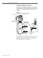
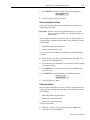
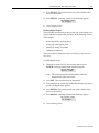
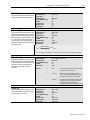
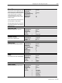
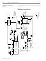
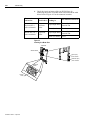
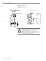
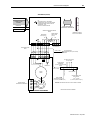
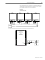
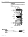
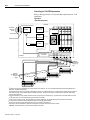
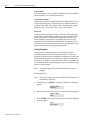
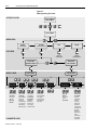
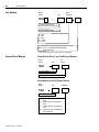
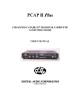
Figure 1.1
Two GMC Turbo Systems (1394x-SJTxx-T)
ALEC
SLC 500
RIO
TM
PanelView 550
AxisLink
845H
Encoder
AxisLink
DH-485
SLC 5/03, 5/04, or 5/05
1394x-SJTxx-T
1
1394x-SJTxx-T
1746-C7 or -C9 1
DANGER
RISK OF ELECTRICAL SHOCK. HIGH VOLTAGE MAY
EXIST UP TO FIVE MINUTES AFTER REMOVING POWER.
1326AB and 1326AS Motors
DANGER
RISK OF ELECTRICAL SHOCK. HIGH VOLTAGE MAY
EXIST UP TO FIVE MINUTES AFTER REMOVING POWER.
1326AB and 1326AS Motors
GML
RS-232/-422
Reset
Axis 0
Axis 1
B
4
3
2
1
5
4
3
2
1
8
7
6
5
10
9
8
7
6
A
SSI
Control
Switches
Encoder Configuration
Axis 0
Axis 1
A
Flex I/O
Switches
B
2
1
Configuration Encoder Power
A
Control
5
4
3
2
1
4
3
2
1
5
Discrete Inputs
Analog Outputs
Analog Inputs
B
10
9
8
7
6
8
7
6
SSI
A
Discrete Outputs
B
842A
Encoder
AEC
Flex I/O 4100-AEC
1
This interface is only available with the 1394x-SJTxx-T system module.
Publication 1394-5.0 — May 2000
1-4
Overview
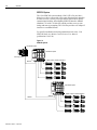
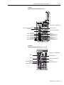
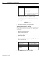
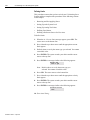
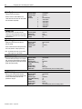
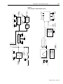
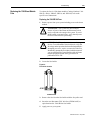
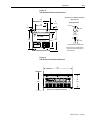
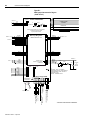
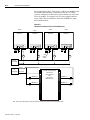
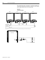
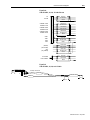
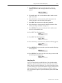
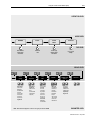
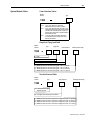
Figure 1.2
Two Standard GMC Systems (1394x-SJTxx-C and 1394C-SJT-xx-L)
SLC 500
ALEC
AxisLink
RIO
845H
Encoder
AxisLink
PanelView 550
1394C-SJTxx-L
DANGER
RISK OF ELECTRICAL SHOCK. HIGH VOLTAGE MAY
EXIST UP TO FIVE MINUTES AFTER REMOVING POWER.
1326AB or 1326AS Motor
DH-485
1394x-SJTxx-C
DANGER
RISK OF ELECTRICAL SHOCK. HIGH VOLTAGE MAY
EXIST UP TO FIVE MINUTES AFTER REMOVING POWER.
1326AB and 1326AS Motors
GML
845H Encoder
RS-232/-422
Flex I/O
Reset
Axis 0
Axis 1
Axis 1
A
B
4
3
2
1
5
4
3
2
1
8
7
6
5
10
9
8
7
6
A
SSI
Control
Switches
Encoder Configuration
Axis 0
2
1
Switches
B
Configuration Encoder Power
A
Control
5
4
3
2
1
4
3
2
1
5
Discrete Inputs
Analog Outputs
Analog Inputs
B
10
9
8
7
6
8
7
6
SSI
A
Discrete Outputs
B
AEC
Flex I/O 4100-AEC
Publication 1394-5.0 — May 2000
842A
Encoder
Overview
1-5
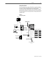
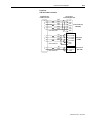
CNC Interface System
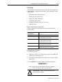
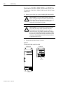
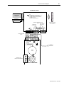
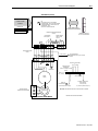
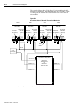
The 1394 9/Series CNC Interface system (1394-SJTxx-E) provides a
digital servo system to be used with the 9/260 and 9/290 CNC. This
system provides all power electronics and uses a cost-saving digital
interface approach. Servo control for this system is handled by the 9/
Series CNC. A fiber optic I/O ring is provided to the 1394 and the
system is completely interfaced with and programmed using ODS
(Off-Line Development System) and the CNC operator panel. AllenBradley Remote I/O, MMS/Ethernet (9/260 and 9/290 only), and
Data Highway Plus (9/260 and 9/290 only) communications are
available options with the 9/Series CNC interface system.
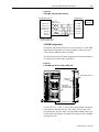
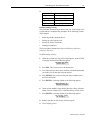
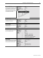
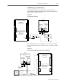
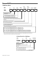
Figure 1.3
CNC Interface System
ODS Software
9/230, 9/260, or
9/290 CNC
1746 I/O
1394
Fiber Optic Ring
Fiber Optic Ring
Fiber Optic Ring
1326AB Motors
RIO
Operator Panel
PLC
R
MTB Panel
Fiber Optic Ring
Publication 1394-5.0 — May 2000
1-6
Overview
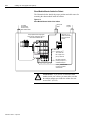
SERCOS System
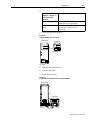
The 1394 SERCOS system module (1394C-SJTxx-D) provides a
digital servo drive system with a fiber-optic digital network interface.
It can be used as a velocity or torque control system and is quickly
commissioned with the Allen-Bradley SERCOS Interface Module
(Bulletin 1756 with 1756-MxxSE), which provides access to auto
tuning and start-up prompting. The 1394 also provides a SCANport
interface as a standard feature.
For specific installation and wiring information refer to the 1394
SERCOS Multi-Axis Motion Control System User Manual
(publication 1394-5.20).
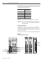
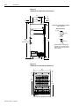
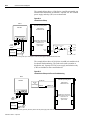
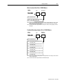
Figure 1.4
SERCOS System
1756-MxxSE Interface
SERCOS System Module
1394 SERCOS System
ControlLogix Chassis
DANGER
RISK OF ELECTRICAL SHOCK. HIGH VOLTAGE MAY
EXIST UP TO FIVE MINUTES AFTER REMOVING POWER.
1326AB, 1326AS, and MP Series Motors
SERCOS
SERCOS System Module
1394 SERCOS System
DANGER
RISK OF ELECTRICAL SHOCK. HIGH VOLTAGE MAY
EXIST UP TO FIVE MINUTES AFTER REMOVING POWER.
1326AB, 1326AS, and MP Series Motors
SERCOS
SERCOS
Publication 1394-5.0 — May 2000
Overview
1-7
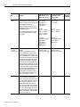
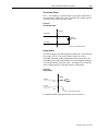
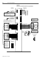
Analog Servo System
The 1394 Analog Servo system (1394x-SJTxx-A) provides a digital
servo drive system with a traditional ±10V DC analog interface. It can
be used as a velocity or torque control system and is quickly
commissioned with the Allen-Bradley universal Bulletin 1201 HIM
(Human Interface Module), which provides access to auto tuning and
start-up prompting. The 1394 also provides a SCANport interface as a
standard feature.
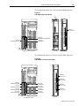
Figure 1.5
Analog Servo System
SLC 500
RIO
Bulletin 1201 HIM
(purchased separately)
PanelView 550
1394
IMC S Class
Compact, Control
Logix (or other
customer supplied
motion controller)
DH-485
GML
RS-232/-422
DANGER
RISK OF ELECTRICAL SHOCK. HIGH VOLTAGE MAY
EXIST UP TO FIVE MINUTES AFTER REMOVING POWER.
1326AB and 1326AS Motors
SCANport
Optional Bulletin 1201
HIM or other remote
SCANport interface
Discrete Outputs
Discrete Inputs
Analog Outputs
Analog Inputs
Flex I/O
Optional Bulletin 1203
Communication Module
To RIO, Serial, DeviceNET,
SLC, etc.
Publication 1394-5.0 — May 2000
1-8
Overview
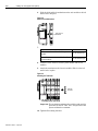
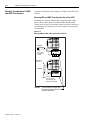
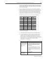
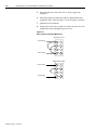
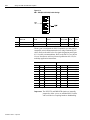
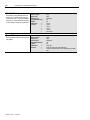
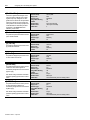
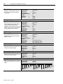
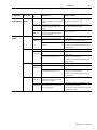
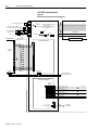
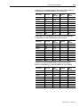
9/440 CNC System
The 9/440 CNC system module gives you all the power and
programming capabilities of a 9/Series CNC, integrated into the
compact packaging of the 1394 System Module. The 9/440 CNC
System Module provides terminating points for:
•
Resolvers
•
Encoder feedback (for optional position feedback or spindle
control)
•
Two serial ports (for communicating with the 9/Series ODS or
other peripherals such as printers or tape readers)
•
E-STOP string and status
•
Spindle outputs
•
9/Series fiber optic ring connection
•
Touch probe interface
•
Remote I/O connection
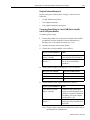
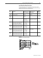
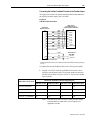
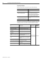
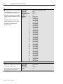
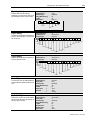
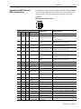
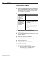
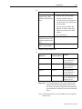
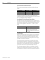
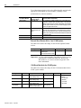
There are three versions of the 9/440 CNC System:
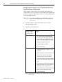
Number of
Version:
Catalog
Number:
Axis
modules:
Resolver
feedback
ports:
Analog
outputs:
Encoder
feedback
ports:
1 Axis 9/440
8520-1Sx
1
1
3 Axis 9/440
8520-3Sx
4 Axis 9/440
8520-4Sx
1
2
2
0
3
1
3
2
11
4
42
2
32
You can connect a total of three feedback devices. If you use three resolvers, the encoder port (J11) is
not available. If you use the encoder feedback port (J11), the third resolver feedback (J3) is disabled.
You can connect a total of six feedback devices. If you use four resolvers, the last encoder port (J11) is
not available. If you use all three encoder feedback ports, the third resolver feedback (J3) is disabled.
For more information on the 9/440, refer to the 9/Series Integration
and Maintenance Manual (publication 8520-6.2).
Publication 1394-5.0 — May 2000
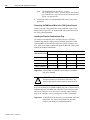
Overview
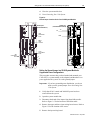
1-9
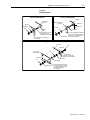
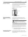
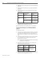
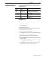
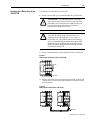
Figure 1.6
9/440 System
Optical signal cable
Terminal type connection
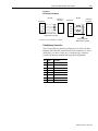
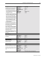
What is a 1394 System?
The 1394 system consists of the following components (catalog number
appears in parenthesis):
•
One System Module (1394x-SJTxx-x)
•
One to four Axis Modules (1394x-AMxx-xx)
•
One to four servo motors (1326Ax-Bxxxx)
•
One to four power and feedback cables
Also available are the DC Link Module (1394-DCLM) and Drive
Interface Module (1394-DIM).
The:
1394-DCLM
1394-DIM
Is used:
In addition to the axis module(s)
In place of an axis module.
Publication 1394-5.0 — May 2000
1-10
Overview
Axis modules are connected to system modules using slide-and-lock,
module-to-module connections. For information on motors and cables,
refer to the 1326AB 460V, Torque Plus Series, AC Servo Motors Product
Data (publication 1326A-2.9), 1326AS Series 460V, Low Inertia,
Brushless Servo Motors Product Data (publication 1326A-2.10), and
1326 Cables for 460V AC Servo Motors Product Data (publication
1326A-2.11).
In addition to the equipment shown above, you will need to supply the
following:
•
Three phase input contactor
•
Three phase input fusing
•
24V AC or DC logic power for system module and contactor
enable (Analog Servo only)/DRIVEOK power (all modules)
Refer to Appendix A for information on these topics.
Note:
An external shunt resistor kit (1394-SR10A) is available for 5
and 10 kW systems with regenerative loads that exceed the
capacity of the internal 200W shunt resistor provided. Most 5
and 10 kW systems will not require a shunt resistor kit. All 22
kW 1394 based products require an external shunt module
(1394-SR9Ax or 1394-SR36Ax). This includes both 1394 and
8520 catalog items.
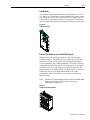
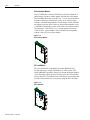
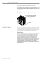
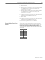
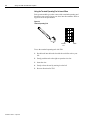
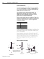
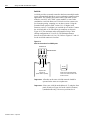
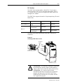
System Modules
System modules, available with ratings of 5, 10 and 22 kW (at 460V),
house the system control PCB and convert 360 to 480VAC, threephase, 50/60 Hz input power to a 530 - 680V DC link voltage. The 5
and 10 kW system modules have an internal shunt resistor with a
200W continuous rating and a peak rating of 40,000W. The 22 kW
system module requires an external shunt module.
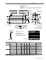
Figure 1.7
1394 System module
ANGER
DANGER
MAY
AGE MA
VOLTAGE
HIGH VOL
RISK OF ELECTRICAL SHOCK.
AFTER REMOVING POWER.
EXIST UP TO FIVE MINUTES
Publication 1394-5.0 — May 2000
Overview
1-11
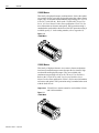
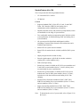
Axis Modules
Axis modules, with continuous output currents (RMS) of 3.0, 4.5, 7.5
23.3 and 35.0A, convert the DC power supplied by the system module
to a variable AC voltage. You will require one axis module for every
1326Ax-Bxxxx servo motor you plan to run using the 1394. Choose
each axis module based on the current requirements of the servo motor.
Figure 1.8
1394 Axis Module
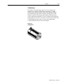
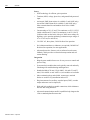
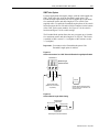
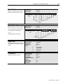
External Shunt Module (used with 22 kW System)
Shunt modules with (rms) power output of 300, 900, 1800 and
3600W continuous, 160,000W peak are available for use with the
smart power 22 kW system module. The shunt module dissipates
excess regenerative power from the Bulletin 1394 system. You must
use one shunt module with each 22 kW smart power system module.
Available in two sizes, each package contains an integral fuse and
terminal block. The 3600W package is available with a 115/230V AC
cooling fan. Choose your shunt module based on the shunt
requirements of the 1326Ax-Bxxxx servo motors you plan to run
using the 1394.
Note:
5 and 10 kW system modules can use an optional 1400W shunt
module kit to dissipate excess regenerative energy
(unpackaged components).
Figure 1.9
1394 External Shunt Module
Publication 1394-5.0 — May 2000
1-12
Overview
1326AB Motors
This family of high-performance, medium inertia, ferrite, three-phase
servo motors feature a specially designed housing that reduces motor
length. They are available with continuous torque ratings of 2.3 to 53.0
N-m (20.7 to 469.0 lb-in.). Refer to the 1326AB 460V, Torque Plus
Series, AC Servo Motors Product Data (publication 1326A-2.9) for
more information on features and options. IP65 protection rating is
standard when used with the shaft oil seal kit. IP67 protection rating is
available (specify -L in the catalog number, refer to Appendix D).
Figure 1.10
1326AB Motor
1326AS Motors
This family of high-performance servo motors feature neodymiumiron-boron permanent magnet rotors that provide low inertias, high
accelerations and high peak torques. They are available with
continuous torque ratings of 0.49 to 49.3 N-m (4.33 to 436 lb-in.).
Refer to the 1326AS Series 460V, Low Inertia, Brushless Servo
Motors Product Data (publication 1326A-2.10) for more information
on features and options. IP65 protection rating is standard when used
with the shaft oil seal.
Important: 1326AS-Bxxxx motors cannot be used with the 9/Series
and 9/440 controllers.
Figure 1.11
1326AS Motor
Publication 1394-5.0 — May 2000
Overview
1-13
1326AH Motors
This family of hazardous duty motors are UL recognized AC
brushless servo motors. Construction of the motor is a totally
enclosed non-ventilated (TENV) square frame design utilizing a
permanent magnet rotor and a fixed stator winding. Rare earth
magnets, long life ball bearings, and brushless construction also
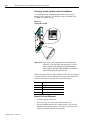
assures maximum performance. They are available with continuous
torque ratings of 2.97 to 16.9 N-m (26.3 to 149.8 lb-in.). Refer to the
1326AH Hazardous Duty Motors Product Data (publication
1326AH-TD001B-US-P) for more information.
Figure 1.12
1326AH Motor
Publication 1394-5.0 — May 2000
1-14
Overview
Drive Interface Module
The 1394-DIM (Drive Interface Module) provides four channels of
analog output, four drive enable outputs, and four drive fault inputs.
The 1394-DIM allows the 1394x-SJTxx-C, -T, or -L system module to
be used to control any external drive with a ±10V velocity torque
reference command and quadrature encoder output. Each 1394-DIM
can support up to four drives. However, the maximum number of axes
(1394-DIM controlled drives plus 1394x-AMxx axis modules) cannot
exceed four per 1394x-SJTxx-C or -T system module and one per
1394C-SJTxx-L system module. The 1394-DIM is not compatible
with the 1394x-SJTxx-A system module.
Figure 1.13
Drive Interface Module
DC Link Module
The 1394-DCLM (DC Link Module) provides additional load
leveling and energy storage (capacitance) for 1394 systems. This
allows additional regenerative energy to be stored during the machine
cycle, increasing system capacity, lowering cycle time, and avoiding
resistive heat loss. The module can be used alone or two modules can
be used to interconnect two 1394 systems using the DC Link cable.
Figure 1.14
DC Link Module
Publication 1394-5.0 — May 2000
Overview
1-15
Standard Features of the 1394
The 1394 provides the following standard features:
•
UL Listed and CUL Certified
•
CE Marked
Control
• Supports Standard GMC (1394x-SJTxx-C and -L) and GMC
Turbo, CNC Interface, SERCOS, and Analog Servo
configurations with a standard array of hardware.
•
Digitally-adjusted velocity and current loop compensation, which
accommodates a wide range of system inertias.
•
Two configurable analog test outputs that can be linked to critical
system parameters for troubleshooting (GMC and Analog Servo
system modules).
•
All systems provide digital fault and diagnostic utilities
(including a current monitor, thermal overload detection, and a
feedback signal monitor).
•
Status LEDs for system and axis modules.
•
Status LEDs for motion board, Axislink, and RIO (GMC system
only).
•
Highly-integrated surface mount circuitry.
•
Encoder signal output (A QUAD B) for encoder emulation
(Analog Servo system modules only).
•
DSP assisted processing.
•
Smart Power control, available on all 22 kW system modules and
5 and 10 kW system modules (Series C or later), allows poweruse monitoring for process optimization.
•
Smart Power system modules, available on all 22 kW system
modules and 5 and 10 kW system modules (Series C or later),
include active Soft Start inrush current limiting for DC link
charging.
•
Electrical Noise Protection included on GMC, GMC Turbo,
SERCOS, and Analog Servo system modules (Series C or later)
and axis modules (Series C or later).
•
Improved grounding terminations on GMC, GMC Turbo,
SERCOS, and Analog Servo system modules (Series C or later)
and axis modules (Series C or later).
Note:
To determine the series of your module, refer to Figure P.1 in
the Preface.
Publication 1394-5.0 — May 2000
1-16
Overview
Power
• IGBT technology for efficient, quiet operation.
•
Transient (MOV) voltage, phase loss, and ground fault protected
input.
•
An integral 200W shunt resistor is available (5 and 10 kW only).
An external 1400W shunt kit is available (5 and 10 kW only).
Other external shunt kits and modules from 300 to 3600W
continuous.
•
Current ratings of 3.0, 4.5, and 7.5A continuous, at 50° C (122° F)
(inside cabinet) and 23.3 and 35A continuous, a t 40°C ( 104°F)
(with heat sinks out the back) with up to 300% motor ratings for
high duty-cycle operation producing continuous torque ranges of
0.7 to 53.0 N-m (6 to 469 lb-in.).
•
324-528V AC, three-phase, 50/60 Hz direct line operation.
•
No isolation transformer or inductors are required (360/480VAC
Hz direct line operation) for most applications.
•
Advanced protective features, such as software-based current
foldback, which provides overload tolerant operation and soft
current limiting.
Integration
• Hinged system module front cover for easy access to control and
power wiring.
Publication 1394-5.0 — May 2000
•
System and axis modules that can be quickly removed and easily
interchanged for troubleshooting and diagnostics.
•
Standard widths of 50 mm (1394x-AM03, -04, and -07) and 75
mm (1394x-AM50-xx and -AM75-xx) axis modules are available.
•
Mass termination plugs and reliable, contact-type, terminal
blocks are used for easy installation and service.
•
Plug interconnects for auxiliary, encoder input (GMC), encoder
output and motor resolver input (all).
•
Slide-and-lock, module-to-module connection, which eliminates
bus bars and wiring harnesses.
•
Advanced communications and I/O capabilities help integrate the
1394 to standard plant floor networks.
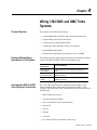
Chapter
2
Installing Your 1394
(applies to all systems)
Chapter Objectives
This chapter covers the following topics:
•
Complying with European Union directives
•
Before mounting your system
•
Unpacking your modules
•
System mounting requirements
•
Bonding your system
•
Mounting your 1394 system
•
Mounting your 1394-DCLM
•
Mounting the external shunt resistor for 5 and 10 kW system
modules
•
Mounting external shunt modules for 22 kW system modules
•
Mounting considerations for GMC and GMC Turbo systems
!
Complying With European Union
Directives
ATTENTION: The following information is a
guideline for proper installation. The National
Electrical Code and any other governing regional or
local codes overrule this information. The AllenBradley Company cannot assume responsibility for the
compliance or the noncompliance with any code,
national, local or otherwise, for the proper installation
of this system or associated equipment. If you ignore
codes during installation, hazard of personal injury
and/or equipment damage exists.
If this product is installed within the European Union or EEC regions
and has the CE mark, the following regulations apply.
EMC Directive
This unit is tested to meet Council Directive 89/336 Electromagnetic
Compatibility (EMC) using a technical construction file and the
following standards, in whole or in part:
•
EN 5008x-2 EMC - Emission Standard, Part 2 - Industrial
Environment
•
EN 5008x-2 EMC - Immunity Standard, Part 2 - Industrial
Environment
Publication 1394-5.0 — May 2000
2-2
Installing Your 1394 (applies to all systems)
The product described in this manual is intended for use in an
industrial environment.
To meet CE requirements, the following additions are required:
•
You must run three-phase input wiring in a conduit that is
grounded to the enclosure.
•
You must install a power line filter (Allen-Bradley catalog
number SP-74102-006-01, SP-74102-006-02, SP-74102-006-03
or equivalent based on system current) between the three-phase
input line and the system module input.
•
You must terminate the shields of the motor power cables and the
motor feedback cables to the enclosure at the point of entry.
Low Voltage Directive
These units are tested to meet Council Directive 73/23/EEC Low
Voltage Directive. The EN 60204-1 Safety of Machinery-Electrical
Equipment of Machines, Part 1-Specification for General
Requirements standard applies in whole or in part.
Refer to Appendix B for interconnect information.
Before Mounting Your System
Before you mount your 1394 system make sure you understand the
following:
•
how to store your 1394 before installation
•
how to unpack the system and axis modules
•
the minimum mounting requirements
•
how to determine your mounting hole layout
Storing Your 1394 Before Installation
The 1394 System module and Axis modules should remain in their
shipping containers prior to installation. If the equipment is not to be
used for a period of time, store it as follows:
Publication 1394-5.0 — May 2000
•
Store the equipment in a clean, dry location that is not exposed to
a corrosive atmosphere.
•
Do not store equipment in a construction area.
•
Store within an ambient temperature range of 0 to 65° C (32 to
149° F).
•
Store within a relative humidity range of 5 to 95%,
noncondensing.
Installing Your 1394 (applies to all systems)
Unpacking Modules
2-3
Each 1394 System module ships with the following:
•
One system module
•
One system terminator
•
One terminal operating tool (part number 1394-194)
•
One user manual (publication 1394-5.0)
•
One application program lock key (GMC and GMC Turbo only)
•
Mating power connectors (5 and 10 kW Series C only)
•
Cable shield grounding clamps (5, 10, and 22 kW Series C only)
Note: To determine the series of your module, refer to Figure P.1 in
the Preface.
Each 1394 Axis Module ships with the following:
•
One 1394 Axis module
•
TB1 and TB2 connectors
•
One 1394 Axis module information sheet (publication 1394-5.5)
Remove all packing material, wedges, and braces from within and
around the components. After unpacking, check the item(s)
nameplate catalog number against the purchase order. Refer to
Appendix D for more information on catalog numbers.
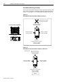
System Mounting Requirements
There are several things that you need to take into account when
preparing to mount the 1394:
•
The ambient temperature of the location in which you will install
the 1394 must not exceed 50° C (122° F).
•
You must install the panel on a flat, rigid, vertical surface that
won’t be subjected to shock, vibration, moisture, oil mist, dust, or
corrosive vapors.
•
You have to mount the system vertically.
•
You need to maintain minimum clearances (see Figure 2.1) for
proper airflow, easy module access, and proper cable bend radius.
Refer to Appendix A for mounting dimensions, power dissipation, and
environmental specifications for the 1394.
Publication 1394-5.0 — May 2000
2-4
Installing Your 1394 (applies to all systems)
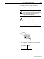
ATTENTION: This drive contains ESD (Electrostatic
Discharge) sensitive parts and assemblies. You are
required to follow static control precautions when you
install, test, service, or repair this assembly. If you do
not follow ESD control procedures, components can be
damaged. If you are not familiar with static control
procedures, refer to Allen-Bradley publication 80004.5.2, Guarding Against Electrostatic Damage or any
other applicable ESD Protection Handbook.
!
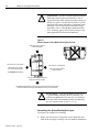
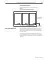
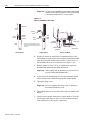
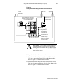
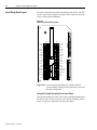
Figure 2.1
Minimum System and Axis Module Mounting Requirements
Allow 10.0 mm (0.4 in.) side clearance.
Allow 25.4 mm (1.00 in.) clearance
at cover tab for opening and closing.
DANGER
RISK OF ELECTRICAL SHOCK. HIGH VOLTAGE MAY
EXIST UP TO FIVE MINUTES AFTER REMOVING POWER.
Status
Allow 50.8 mm (2.00 in.) clearance
for airflow and installation.
Allow 10.0 mm (0.4 in.) side clearance.
Status
Allow 76.2 mm (3.00 in.) clearance
for depth of terminator.
DANGER
RISK OF ELECTRICAL SHOCK. HIGH VOLTAGE MAY
EXIST UP TO FIVE MINUTES AFTER REMOVING POWER.
(See ATTENTION: statement below)
Wire entry area for cable ground clamps and
signal, power, and motor connections.
Allow additional clearance below the system module to provide the recommended cable bend radius.
Refer to 1326 Cables for 460V AC Servo Motors (publication 1326A-2.11) for more information.
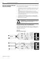
!
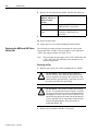
ATTENTION: If you are mounting a 1394x-SJTxxT system module, and using the SLC Interface, you
will need an additional 101.6 mm (4 in.) of clearance
to the left of the system module to allow for connecting
the SLC interface cable (1746-C7 or -C9).
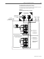
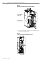
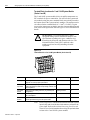
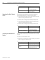
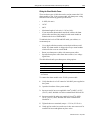
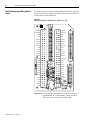
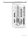
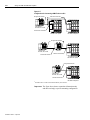
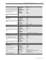
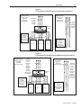
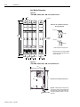
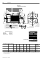
Determining Your System Mounting Hole Layout
To prepare your subpanel for mounting:
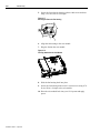
1. Before you mount your 1394 System, use the illustration and
table on the next page to identify your axis module combination.
Publication 1394-5.0 — May 2000
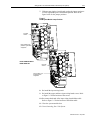
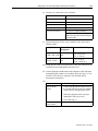
Installing Your 1394 (applies to all systems)
2-5
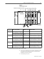
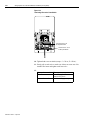
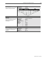
Figure 2.2
1394 Mounting Hole Layout
62.5 100 137.5 175 212.5 250 287.5
(2.46) (3.94) (5.41) (6.89) (8.37) (9.84) (11.32)
125 150
50
275
200 225
(4.92) (5.91) (7.87) (8.86) (10.83)
(1.97)
Dimensions are in millimeters and (inches)
50
(1.97)
0
(0.00)
System module
mounting holes
System
outline
385
(15.16)
Heat sink
cutout for the
AM50/75
module
only
33.5 TYP
(1.32)
Axis Module
Type of Axis Module
Combination
A
B
C
D
E
A B
C
D
E
A
B C A
D
E
Heat sink
cutout for the
AM50/75
module
only
B
A D B
C E
Heat sink
cutout for the
AM50/75
module
only
C
D E
Heat sink
cutout for the
AM50/75
module
only
348
(13.70)
M6 tapped hole or
1/4-20 UNC - 2B
8 TYP
(0.32)
67 TYP
(2.64)
19.5
(0.768)
Number of Axes Cutout Needed?
1394x-AM50, or -AM75, and
0
1394C-AM50-IH, or -AM75-IH
no
1394x-AM03, AM04, or AM07
no
up to 4
1394x-AM50, or -AM75, and
1
1394C-AM50-IH, or -AM75-IH
yes (1394x-AM50 or -AM75)
no (1394C-AM50-IH or -AM75-IH)
1394x-AM03, AM04, or AM07
no
up to 3
1394x-AM50, or -AM75, and
2
1394C-AM50-IH, or -AM75-IH
yes (1394x-AM50 or -AM75)
no (1394C-AM50-IH or -AM75-IH)
1394x-AM03, AM04, or AM07
no
up to 2
1394x-AM50, or -AM75, and
3
1394C-AM50-IH, or -AM75-IH
yes (1394x-AM50 or -AM75)
no (1394C-AM50-IH or -AM75-IH)
1394x-AM03, AM04, or AM07
no
up to 1
1394x-AM50, or -AM75, and
4
1394C-AM50-IH, or -AM75-IH
yes (1394x-AM50 or -AM75)
no (1394C-AM50-IH or -AM75-IH)
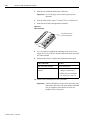
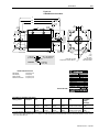
Note: When mounting axis module combinations, you must mount the 1394x-AM50, -AM75, -AM50-IH, and -AM75-IH closest to the system
module and ahead of the 1394x-AM03, -AM04, and -AM07 axis modules.
2. Once you have identified your axis module combination, modify
your subpanel using the dimensions that correspond with the
combination you chose in step one.
3. Go to Bonding Your System.
Publication 1394-5.0 — May 2000
2-6
Installing Your 1394 (applies to all systems)
Mounting Your 1394 Through the Back of the Cabinet
The figure below shows an example of the typical mounting of a 1394
system with 1394x-AM50 or -AM75 axis modules. The 1394x-AM50
and -AM75 have heatsinks that mount through the back of the
electrical cabinet.
Figure 2.3
Mounting the 1394 with heatsinks through the back of the cabinet
Note: This configuration requires a gasket between
the 1394x-AM50 or -AM75 and the inside of
the enclosure. Use the gasket provided.
Customer-supplied
enclosure
Bonding Your System
After you have established your panel layout, you need to understand
how to bond your system and subpanels. Bonding is the practice of
connecting metal chassis, assemblies, frames, shields and enclosures
to reduce the effects of electromagnetic interference (EMI).
Bonding Modules
Unless specified, most paints are not conductive and act as insulators.
To achieve a good bond between modules and the subpanel, the
surfaces need to be paint-free or plated. Bonding metal surfaces
creates a low impedance exit path for high frequency energy.
Improper bonding blocks that direct exit path and allows high
frequency energy to travel elsewhere in the cabinet. Excessive high
frequency energy can effect the operation of other microprocessor
controlled equipment. The illustrations below show details of
recommended bonding practices for painted panels, enclosures and
mounting brackets.
Publication 1394-5.0 — May 2000
Installing Your 1394 (applies to all systems)
2-7
Figure 2.4
Bonding Examples
Stud-mounting a ground bus
or chassis to the subpanel
Stud-mounting the subpanel
to the enclosure back wall
Subpanel
Back wall of
enclosure
Mounting bracket or
ground bus
Subpanel
Star washer
Nut
Welded stud
Scrape paint
Flat washer
Welded
stud
Flat washer
Nut
Use a wire brush to remove
paint from threads to
maximize ground connection.
Star washer
Use plated panels or scrape paint on
front of panel
If the mounting bracket is coated with
a non-conductive material (anodized,
painted, etc.), scrape the material
around the mounting hole.
Bolt-mounting a ground bus or chassis to the back-panel
Subpanel
Bolt
Tapped hole
Ground bus or
mounting bracket
Nut
Star washer
Scrape paint on both sides
of panel and use star washers.
Star washer
Flat washer
Nut
Flat washer
Star washer
If the mounting bracket is coated
with a non-conductive material
(anodized, painted, etc.), scrape
the material around each
mounting hole.
Publication 1394-5.0 — May 2000
2-8
Installing Your 1394 (applies to all systems)
Bonding Multiple Subpanels
Bonding multiple subpanels creates a common low impedance exit
path for the high frequency energy inside the cabinet. Subpanels that
are not bonded together may not share a common low impedance
path. This difference in impedance may affect networks and other
devices that span multiple panels. Refer to the illustration below for
recommended bonding practices.
Figure 2.5
Bonding Multiple Subpanels
Recommended:
Bond the top and bottom of each subpanel
to the cabinet using 25.4 mm (1.0 in.) by 6.35 mm (.25 in.) (minimum) wire braid
Bonded cabinet
ground bus
to subpanel
Scrape the paint around each fastener to maximize
metal-to-metal contact
Mounting Your 1394 System
The procedures in this section assume you have prepared your panel
and understand how to bond your system. To mount your 1394
system:
1. Install the top mounting fasteners on the subpanel for the system
module and all axis modules. The heads of the fasteners should be
at least 0.25 in. from the panel. Make sure all fasteners are
properly bonded to the subpanel. Refer to Bonding Your System
for more information.
2. Hang the 1394 System Module on the two fasteners on the left
side of the subpanel.
Important: If you are mounting a GMC Turbo system module
(1394x-SJTxx-T), and using the SLC interface, you
will need an additional 101.6 mm (4 in.) of clearance
to the left of the system module to allow for
connecting the SLC interface cable (1746-C7 or -C9).
Publication 1394-5.0 — May 2000
Installing Your 1394 (applies to all systems)
2-9
3.
If you are mounting a:
1394x-AM03, -AM04 or
-AM07; 1394C-AM50IH, or -AM75-IH axis
module
1394x-AM50 or -AM75
axis module with the
heat sink through the
back of the enclosure
(refer to Figure 2.3)
Do this:
1. Hang the axis module on the next
mounting fastener.
2. Go to main step 5.
1. Remove the paper backing from
the gasket that came with the
AM50/75 axis module.
2. Position the gasket so that the
sticky side faces the axis module
and the small hole side is on top.
3. Slide the gasket over the heat sink
and attach it to the back of the axis
module.
Figure 2.6
Gasket Position
gasket
1394-DCLM or
1394-DIM
4. Go to main step 4.
1. Hang the DCLM or the DIM as the
last (right-most) module.
Note: If both DCLM and DIM are
mounted on the same
system, the DIM should be
the last module.
2. Go to main step 5.
4. Hang the AM50/75 axis module on the next mounting fastener.
5. Engage the alignment tab (refer to Figure 2.7).
Figure 2.7
Alignment Tab
Engaged alignment tab
Publication 1394-5.0 — May 2000
2-10
Installing Your 1394 (applies to all systems)
6. Slide the slide-and-lock mechanism on the axis module to the left
until it locks into place.
Figure 2.8
Slide-and Lock Mechanism
Slide-and-Lock
Mechanism
Status
DANGER
RISK OF ELECTRICAL SHOCK. HIGH VOLTAGE MAY
EXIST UP TO FIVE MINUTES AFTER REMOVING POWER.
7.
If you:
Have more axis modules for this system
module
Do not have more axis modules for this
system module
Do this:
Go to main step 3.
Go to main step 8.
8. Install the lower fasteners for the system module and all axis
modules.
9. Attach the terminator to the last axis module. Slide it to the left
until it locks in place.
Figure 2.9
Attaching the Terminator
Attach the
Terminator
Status
DANGER
RISK OF ELECTRICAL SHOCK. HIGH VOLTAGE MAY
EXIST UP TO FIVE MINUTES AFTER REMOVING POWER.
Important: The terminator terminates the serial ring and provides
protection for the DC Link. The 1394 system will not
operate without the terminator.
10. Tighten all mounting fasteners.
Publication 1394-5.0 — May 2000
Installing Your 1394 (applies to all systems)
Mounting Your 1394-DCLM
2-11
Two 1394 system power buses can be linked by connecting two
DCLMs together. This procedure is application specific and requires
proper implementation. Please contact your Allen-Bradley sales
representative for more information.
When using the 1394-DCLM for energy storage, the power plug must
be installed (refer to Figure 2.10 for location).
Figure 2.10
Locating the Power Plug
Allen-Bradley
DC Link Module
1394 Digital Servo Controller
System Module
DC Link
Module
DANGER
RISK OF ELECTRICAL SHOCK. HIGH VOLTAGE MAY
EXIST UP TO FIVE MINUTES AFTER REMOVING POWER.
Power Plug
Mounting the External Shunt
Resistor for 5 and 10 kW System
Modules
If your 5 or 10 kW 1394 system module requires a means of
dissipating regenerative energy that exceeds the capacity of the
internal shunt resistor, install a 1394 External Shunt Resistor Kit
(catalog number 1394-SR10A).
!
ATTENTION: To avoid the hazard of shock or burn
and ignition of flammable material, appropriate
guarding must be provided. These resistors can reach
temperatures in excess of 350° C (662° F). Install per
local codes.
To install the 1394-SR10A Shunt Resistor Kit use two M10 (3/8 in.)
bolts and mount the external shunt resistor assembly vertically on a
flat rigid metal surface that will not be subjected to shock, vibration,
moisture, oil mist, dust or corrosive vapors.
Note: To extend the leadwire length up to 15 m (49 ft total overall
length), use MTW, 105° C, (302° F) Class H insulated wire (UL
styles 3349, 3374, or equivalent).
Mounting External Shunt Modules
for 22 kW System Modules
If you are using a 22 kW system module, you must use a shunt
module (1394-SR9A, -SR9AF, -SR36A or -SR36AF). An external
shunt module is required for 22 kW system modules because there is
no internal shunt resistor.
Publication 1394-5.0 — May 2000
2-12
Installing Your 1394 (applies to all systems)
Shunt Module Mounting Orientation
Because the shunt module dissipates excess regenerative power in the
form of heat, you need to consider the following guidelines. Refer to
Figure 2.11 and Figure 2.12 for shunt module spacing requirements.
Figure 2.11
Shunt Module Spacing Requirements Within an Enclosure
Temperature sensitive component
(mounted above shunt module)
254 mm (10.0 in.) clearance
for airflow and installation
Incorrect Shunt Placement
1394 Digital Servo Controller
3600W Shunt Module
155 mm (6.1 in.) clearance
for airflow and installation
155 mm (6.1 in.) clearance
for airflow and installation
Top of cabinet
ALLEN-BRADLEY
R
BULLETIN 1394 3600W SHUNT MODULE
CAT.
PART
SER.
INPUT DC
INPUT AC
FOR FUSE REPLACEMENT USE:
BUSSMAN CAT. NO.
R
ALLEN-BRADLEY
FOR USE WITH 1394-SJT22-X SYSTEM MODULE
BULLETIN 1394 3600W SHUNT MODULE
CAT.
PART
SER.
INPUT DC
INPUT AC
FOR FUSE REPLACEMENT USE:
BUSSMAN CAT. NO.
1394 Digital Servo Controller
3600W Shunt Module
FOR USE WITH 1394-SJT22-X SYSTEM MODULE
Wire entry area
for signal, power and motor connections
155 mm (6.1 in.) clearance
for airflow and installation
Figure 2.12
Shunt Module Spacing Requirements Outside of an Enclosure
Solid protective plate
254 mm (10.0 in.) clearance
for airflow and installation
1394 Digital Servo Controller
3600W Shunt Module
155 mm (6.1 in.) clearance
for airflow and installation
155 mm (6.1 in.) clearance
for airflow and installation
ALLEN-BRADLEY
R
BULLETIN 1394 3600W SHUNT MODULE
CAT.
PART
SER.
INPUT DC
INPUT AC
FOR FUSE REPLACEMENT USE:
BUSSMAN CAT. NO.
FOR USE WITH 1394-SJT22-X SYSTEM MODULE
Wire entry area
for signal, power and motor connections
155 mm (6.1 in.) clearance
for airflow and installation
Enclosure
Publication 1394-5.0 — May 2000
Installing Your 1394 (applies to all systems)
2-13
Shunt Module Mounted Outside the Cabinet
The illustration below details the proper position and cable routes for
mounting the shunt module outside the cabinet.
Figure 2.13
Shunt Module Mounted Outside of the Cabinet
Customer-supplied
metal enclosure (optional)
Low voltage
Communications
Control I/O wiring
Motor feedback cables
155 mm (6.1 in.) of
clearance on all sides
of the shunt module
minimum
1394 Digital Servo Controller
300W Shunt Module
1394 Digital Servo Controller
300W Shunt Module
ALLEN-BRADLEY
ALLEN-BRADLEY
R
R
BULLETIN 1394 300W SHUNT MODULE
CAT.
PART
SER.
INPUT DC
INPUT AC
FOR FUSE REPLACEMENT USE:
BUSSMAN CAT. NO.
BULLETIN 1394 300W SHUNT MODULE
CAT.
PART
SER.
INPUT DC
INPUT AC
FOR FUSE REPLACEMENT USE:
BUSSMAN CAT. NO.
FOR USE WITH 1394-SJT22-X SYSTEM MODULE
FOR USE WITH 1394-SJT22-X SYSTEM MODULE
Motor power
cables
360/480V
AC power
Metal
conduit
Status
DANGER
RISK OF ELECTRICAL SHOCK. HIGH VOLTAGE MAY
EXIST UP TO FIVE MINUTES AFTER REMOVING POWER.
8 AWG (8.4 mm2),
105 C, 600V wire
Max. Length 3.05 m
(10 ft) for each wire
Always separate all low voltage signal
wiring from high voltage power wiring to
reduce affects of EMI and RFI.
Twisted conductors
(2 twists per foot) min. or
a shielded twisted pair
Shielding is recommended
for reducing the effects
of EMI and RFI.
Status
DANGER
RISK OF ELECTRICAL SHOCK. HIGH VOLTAGE MAY
EXIST UP TO FIVE MINUTES AFTER REMOVING POWER.
Publication 1394-5.0 — May 2000
2-14
Installing Your 1394 (applies to all systems)
Shunt Module Mounted Inside the Cabinet
The illustration below details the proper position and cable routes for
mounting the shunt module inside the cabinet.
Figure 2.14
Shunt Module Mounted Inside of the Cabinet
Motor power
cables
Low voltage
Communications
Control I/O wiring
Motor feedback cables
360/480V
AC power
155 mm (6.1 in.) of
clearance on all sides
of the shunt module
minimum
Always separate all low voltage signal
wiring from high voltage power wiring to
reduce affects of EMI and RFI.
1394 Digital Servo Controller
300W Shunt Module
ALLEN-BRADLEY
R
BULLETIN 1394 300W SHUNT MODULE
CAT.
PART
SER.
INPUT DC
INPUT AC
FOR FUSE REPLACEMENT USE:
BUSSMAN CAT. NO.
FOR USE WITH 1394-SJT22-X SYSTEM MODULE
Status
DANGER
8 AWG (8.4 mm2),
105 C, 600V wire
RISK OF ELECTRICAL SHOCK. HIGH VOLTAGE MAY
EXIST UP TO FIVE MINUTES AFTER REMOVING POWER.
Max. Length 3.05 m
(10 ft) for each wire
Use twisted conductors
(2 twists per foot) min. or
a shielded twisted pair.
Shielding is recommended
for reducing the effects
of EMI and RFI.
!
Publication 1394-5.0 — May 2000
ATTENTION: If you choose to mount the shunt
module inside your cabinet, you must make sure that
the ambient temperature inside the cabinet does not
exceed 50° C (122° F).
Installing Your 1394 (applies to all systems)
2-15
Mounting the Shunt Module
The procedures in this section assume you have prepared your panel
and understand how to bond your system. To mount your 1394 Shunt
Module:
1. Install the top mounting fasteners on the subpanel for the shunt
module. The heads of both fasteners should be at least 6.35 mm
(0.25 in.) from the panel. Make sure the fasteners are properly
bonded to the subpanel. Refer to Bonding Your System for more
information.
2. Hang the 1394 Shunt Module on the two fasteners.
3. Install the lower fasteners for the shunt module.
4. Tighten all mounting fasteners.
Publication 1394-5.0 — May 2000
2-16
Installing Your 1394 (applies to all systems)
Mounting Considerations for GMC
and GMC Turbo Systems
Consider the following when mounting 1394 GMC and GMC Turbo
Systems.
Mounting GMC and GMC Turbo Systems Next to Flex I/O
Separating low voltage communication wiring from high voltage
power cables reduces the levels of EMI and RFI. Because high
voltage motor wiring is present at the bottom of each axis module we
recommend that you mount your Flex I/O modules to the left of the
system module.
Figure 2.15
Mounting GMC and GMC Turbo Systems Next to Flex I/O
Preferred
Status
DANGER
RISK OF ELECTRICAL SHOCK. HIGH VOLTAGE MAY
EXIST UP TO FIVE MINUTES AFTER REMOVING POWER.
Install
Flex I/O to the
left of the axis
modules
Bond DIN rail
to sub panel
Status
Preferred
DANGER
RISK OF ELECTRICAL SHOCK. HIGH VOLTAGE MAY
EXIST UP TO FIVE MINUTES AFTER REMOVING POWER.
Screw Flex I/O
connector to tapped
hole in sub panel. This
grounds flex cable shields.
Important:
Publication 1394-5.0 — May 2000
You must separate low voltage I/O from
all exposed high voltage conductors to avoid
the affects of EMI and RFI.
Chapter
3
Wiring System, Axis, and Shunt
Modules, and Motors
(for all systems)
Chapter Objectives
Finding Additional Wiring
Information for 1394 Systems
This chapter covers the following topics:
•
Understanding basic wiring requirements
•
Determining your type of input power
•
Grounding your 1394 system
•
Connecting system module power
•
Connecting motor power to axis modules
•
Connecting feedback to system modules
•
Connecting your motor cables to motors
•
Connecting your external shunt resistor
•
Connecting your shunt module (required for 22 kW system)
The information and procedures included in this chapter apply to the
following 1394 systems; GMC Turbo, GMC, 9/440 CNC, CNC
Interface, and Analog Servo.
For additional wiring
information on:
Refer to the following:
GMC or GMC Turbo
system modules
Chapter 4 (Wiring 1394 GMC and GMCTurbo Systems) in this
manual.
1394 Analog Servo
system modules
Chapter 5 (Wiring Your 1394 Analog Servo System) in this
manual.
CNC Interface or
9/440 system modules
9/Series CNC Hardware Integration and Maintenance Manual
(publication 8520-6.2).
1394 SERCOS system
modules
1394 SERCOS Multi-Axis Motion Control System User Manual
(publication 1394-5.20)
Publication 1394-5.0 — May 2000
3-2
Wiring System, Axis, and Shunt Modules, and Motors (for all systems)
Understanding Basic Wiring
Requirements
This section contains basic wiring information for the 1394.
!
ATTENTION: Plan the installation of your system
so that you can perform all cutting, drilling, tapping,
and welding with the system removed from the
enclosure. Because the system is of the open type
construction, be careful to keep any metal debris from
falling into it. Metal debris or other foreign matter can
become lodged in the circuitry, which can result in
damage to components.
Important: This section contains common PWM servo system
wiring configurations, size, and practices that can be
used in a majority of applications. National Electrical
Code, local electrical codes, special operating
temperatures, duty cycles, or system configurations take
precedence over the values and methods provided.
Publication 1394-5.0 — May 2000
Wiring System, Axis, and Shunt Modules, and Motors (for all systems)
3-3
Routing High and Low Voltage Cables
Be aware that when you connect and route power and signal wiring
on a machine or system, radiated noise from nearby relays (relay coils
should have surge suppressors), transformers, and other electronic
drives can be induced into motor or encoder feedback,
communications, or other sensitive, low voltage signals. This can
cause system faults and communication problems. To minimize the
levels of radiated noise, route machine power and signal lines
separately.
Figure 3.1
Routing Cables Inside Your Cabinet
Low voltage
Communications
Control I/O wiring
Motor feedback cables
Motor power
cables
Always separate all low voltage signal wiring
from high voltage power wiring to reduce affects
of EMI and RFI.
460/380V
AC power
Always cross high and low voltage
conductors at 90 degree angles.
Unshielded
conductors
Status
Status
DANGER
DANGER
RISK OF ELECTRICAL SHOCK. HIGH VOLTAGE MAY
EXIST UP TO FIVE MINUTES AFTER REMOVING POWER.
RISK OF ELECTRICAL SHOCK. HIGH VOLTAGE MAY
EXIST UP TO FIVE MINUTES AFTER REMOVING POWER.
Maximize
distance
between high
and low voltage
cables on
parallel runs
Status
Status
DANGER
RISK OF ELECTRICAL SHOCK. HIGH VOLTAGE MAY
EXIST UP TO FIVE MINUTES AFTER REMOVING POWER.
Do not run low
and high voltage
wires in the
same wire way
DANGER
RISK OF ELECTRICAL SHOCK. HIGH VOLTAGE MAY
EXIST UP TO FIVE MINUTES AFTER REMOVING POWER.
Unshielded lead length
less than or equal to
76.2 mm (3.0 in.)
Publication 1394-5.0 — May 2000
3-4
Wiring System, Axis, and Shunt Modules, and Motors (for all systems)
System Module Wire Sizes
All wire sizes in this manual are recommended minimums. Assume
that wires are type MTW copper wire (machine tool wire, 75° C,
minimum) per NFPA 79 unless otherwise noted. Consult the National
(or local) Electrical Code for factors related to ambient conditions,
length, etc. See your Allen-Bradley Sales Representative for more
information.
Shielding
To minimize radiated and induced noise problems or ground loops,
separate feedback, command, and other shields from each other and
connect them at a common machine or system earth ground. Connect
all shields to a single earth ground point. Refer to Grounding Your
1394 System in this chapter and Appendix B for additional
information.
Insulate the open-ended shields (resolver feedback cable at the
resolver and velocity command cable at the servo drive) so that they
do not cause ground loops.
EMI/RFI Shielding
The 1394 has an inverter carrier frequency of 5000 Hz. The drive’s
output inverter switching sequence produces a carrier frequency of
10,000 Hz when measured at the motor. This can induce noise into
sensitive equipment lines adjacent to it.
!
ATTENTION: This system can produce
electromagnetic radiation that can cause industrial or
radio-controlled equipment to operate erratically and
cause possible injury to personnel. The 1394 system is
designed to be interconnected with Allen-Bradley EMI
shielded motor cables only. Do not substitute cables.
The EMI shield of the motor power cable must be
grounded at both ends to function properly.
EMI/RFI Bonding
The metal chassis of electrical components should be bonded to the
subpanel in an electrical cabinet with metal to metal contact. The
purpose of a high frequency (HF) bond is to provide HF noise
currents a path of least impedance to return to their source.
Publication 1394-5.0 — May 2000
Wiring System, Axis, and Shunt Modules, and Motors (for all systems)
3-5
Input Power Conditioning
You can directly connect the 1394 to a three-phase, AC power line.
However, if certain power line conditions exist, the input power
component can malfunction. If either of the following is true, you can
use a line reactor or isolation-type transformer to reduce the
possibility of this type of malfunction:
•
The AC line supplying the drive has power factor correction
capacitors.
•
The AC line frequently experiences transient power interruptions
or significant voltage spikes.
Important: Line conditioning is not typically required. If you have
experienced power problems in the past on a power
distribution line, you may need to consider input power
conditioning.
!
ATTENTION: The 1394 does not supply line fuses
or a circuit breaker. They are customer-supplied items.
Branch circuit breakers or disconnect switches cannot
provide the level of protection required by drive
components. Refer to Appendix A for size and type
recommendations.
Publication 1394-5.0 — May 2000
3-6
Wiring System, Axis, and Shunt Modules, and Motors (for all systems)
Determining Your Type of Input
Power
Before you ground or wire your 1394 system you must determine the
type of 360/480V input power you will be connecting to. The 1394
system is designed to operate in both grounded and ungrounded
environments.
Grounded Power Configuration
As shown in the figure below, the grounded power configuration
allows you to ground your 3-phase power at a neutral point. Each
1394 system module has a factory-installed jumper configured for
grounded power distribution. If you determine that you have
grounded power distribution in your plant you do not need to modify
your system.
Figure 3.2
Grounded Power Configuration
Status
DANGER
RISK OF ELECTRICAL SHOCK. HIGH VOLTAGE MAY
EXIST UP TO FIVE MINUTES AFTER REMOVING POWER.
Conduit/4-Wire Cable
U
V
W
PE
PE1
Ground grid or
Power distribution ground
Publication 1394-5.0 — May 2000
PE3 (drain/shield)
PE2 (wire 8)
W1 (wire 3)
V1 (wire 2)
U1 (wire 1)
1326 motor
power cable
Wiring System, Axis, and Shunt Modules, and Motors (for all systems)
3-7
Ungrounded Power Configuration
As shown in the figure below, the ungrounded power configuration
does not allow for a neutral ground point. If you determine that you
have ungrounded power distribution in your plant, you need to move
the factory-installed jumper to the ungrounded power distribution
position to prevent electrostatic buildup inside the 1394. Refer to the
ground jumper procedures for the system module you need to
configure.
Figure 3.3
Ungrounded Power Configuration
Status
DANGER
RISK OF ELECTRICAL SHOCK. HIGH VOLTAGE MAY
EXIST UP TO FIVE MINUTES AFTER REMOVING POWER.
Conduit/4-Wire Cable
U
PE3 (drain/shield)
PE2 (wire 8)
W1 (wire 3)
V1 (wire 2)
U1 (wire 1)
V
W
PE
1326 motor
power cable
PE1
Ground grid or
Power distribution ground
!
ATTENTION: Ungrounded systems do not reference
each phase potential to a power distribution ground.
This can result in an unknown potential to earth ground.
Publication 1394-5.0 — May 2000
3-8
Wiring System, Axis, and Shunt Modules, and Motors (for all systems)
Setting the Ground Jumper in a 5 or 10 kW System Module for
Ungrounded Power Configurations
This procedure assumes that you have bonded and mounted your
1394x-SJT05-x or 1394x-SJT10-x system module to the subpanel and
that there is no power applied to the system. To set the ground jumper
for an ungrounded system:
Important: If you have grounded power distribution, you do not
need to set the ground jumper. Go to Grounding Your
1394 System.
1. Verify that all 24V control and 360/480V power has been
removed from the system.
2. Open the system module door.
3.
For ground jumper
settings on this
Do this:
system module:
Series A and B
1. Locate the jumper connected to J26 and
J27 on the circuit board behind the
Danger label in the upper right hand
corner of the system module (refer to
Figure 3.4 for the jumper’s location).
2. Unplug the jumper from J26.
3. Plug the jumper in GND3.
4. Go to main step 4.
Series C
1. Unplug the ribbon cable from the input
wiring board (refer to Figure 3.4 for
location).
2. Remove the three control board screws.
3. Remove the control board (pull it
straight out from system module).
4. Locate the jumper connecting J4 and J5,
and move one end of the jumper from J5
to J6.
5. Re-install the control board. Align the
guide pins in the rear of the enclosure
with holes in the control board.
6. Re-install the three control board screws
and re-connect the ribbon cable.
7. Go to main step 4.
Note: To determine the series of your module, refer to Figure P.1
in the Preface.
Publication 1394-5.0 — May 2000
Wiring System, Axis, and Shunt Modules, and Motors (for all systems)
3-9
4. Close the system module door.
5. Go to Grounding Your 1394 System.
Figure 3.4
Ground Jumper Locations for the 5 and 10 kW System Modules
1394C-SJTxx-x
(5 and 10 kW Series C)
1394-SJTxx-x
(5 and 10 kW Series A and B)
J26
Upper
Control Board
Screw
J27
GND3
Ribbon
Cable
Connector
Side
Control Board
Screw
Lower
Control Board
Screw
J4
J5
J6
Setting the Ground Jumper in a 22 kW System Module for
Ungrounded Power Configurations
This procedure assumes that you have bonded and mounted your
1394x-SJT22-x system module to the subpanel and that there is no
power applied to the system. To set the ground jumper:
Important: If you have grounded power distribution, you do not
need to set the ground jumper. Go to Grounding Your
1394 System.
1. Verify that all 24V control and 360/480V power has been
removed from the system.
2. Open the system module door.
3. Disconnect both ends of the input wiring board ribbon cable.
Refer to Figure 3.5 for the location of the ribbon cable.
4. Remove the upper and lower input wiring board screws. Refer to
Figure 3.5 for the location of the screws.
5. Remove the input wiring board.
Publication 1394-5.0 — May 2000
3-10
Wiring System, Axis, and Shunt Modules, and Motors (for all systems)
Figure 3.5
Removing the Input Wiring Board in a 22 kW System Module
Disconnect both sides of
the ribbon cable
Remove both input
wiring board screws and
remove the input wiring board
6. Locate the ground jumper inside the system module. Refer to the
figure below for jumper location.
Figure 3.6
Location of the 22 kW System Module Ground Jumper
Ground Jumper
Publication 1394-5.0 — May 2000
Wiring System, Axis, and Shunt Modules, and Motors (for all systems)
3-11
7. Without removing the circuit board, unplug the jumper and move
it to the ungrounded power distribution position. Refer to the
figure below for the jumper positions.
Figure 3.7
22 kW System Module Jumper Positions
Front edge
of board
Factory default jumper
position for a grounded
configuration
DO NOT REMOVE CIRCUIT
BOARD FROM 1394
Front edge
of board
Jumper position for an
ungrounded power
configuration
8. Re-install the input wiring board.
9. Re-install the upper and lower input wiring board screws. Refer
to Figure 3.5 for the location of the screws.
10. Re-connect both ends of the input wiring board ribbon cable.
Refer to Figure 3.5 for the location of the ribbon cable.
11. Close the system module door.
12. Go to Grounding Your 1394 System.
Publication 1394-5.0 — May 2000
3-12
Wiring System, Axis, and Shunt Modules, and Motors (for all systems)
Grounding Your 1394 System
We recommend that all equipment and components of a machine or
process system have a common earth ground point connected to their
chassis. A grounded system provides a safety ground path for short
circuit protection. Grounding your modules and panels minimizes
shock hazards to personnel and damage to equipment caused by short
circuits, transient overvoltages, and accidental connection of
energized conductors to the equipment chassis.
Grounding your System to the Subpanel
The National Electrical Code contains grounding requirements,
conventions, and definitions. Follow all applicable local codes and
regulations to safely ground your system. Refer to the illustration
below for details on grounding your system and axis modules. Refer
to Appendix B for interconnect information.
Figure 3.8
PE Safety Ground Configuration with Multiple 1394 Systems on One Panel
22 kW or
5 and 10 kW
System Modules
(Series A and B)
Status
DANGER
RISK OF ELECTRICAL SHOCK. HIGH VOLTAGE MAY
EXIST UP TO FIVE MINUTES AFTER REMOVING POWER.
Connect the system
module's PE and each axis
module's PE1 to the PE bar
Status
DANGER
RISK OF ELECTRICAL SHOCK. HIGH VOLTAGE MAY
EXIST UP TO FIVE MINUTES AFTER REMOVING POWER.
Bonded PE
ground bar
All ground wiring must
comply with local codes
Status
DANGER
RISK OF ELECTRICAL SHOCK. HIGH VOLTAGE MAY
EXIST UP TO FIVE MINUTES AFTER REMOVING POWER.
System module
ground bar
22 kW or
5 and 10 kW
System Modules
(Series C or later)
Status
DANGER
RISK OF ELECTRICAL SHOCK. HIGH VOLTAGE MAY
EXIST UP TO FIVE MINUTES AFTER REMOVING POWER.
System module
ground bar
Always follow NEC and
applicable local codes
Ground grid or power
distribution ground
Bonded cabinet ground bus
Publication 1394-5.0 — May 2000
Wiring System, Axis, and Shunt Modules, and Motors (for all systems)
3-13
Grounding Multiple Subpanels
To ground multiple subpanels, refer to the figure below.
Figure 3.9
Subpanels Connected to a Single Ground Point
Always follow NEC and
applicable local codes
Ground grid or power
distribution ground
Wiring System Module Power
The system module provides terminating points for the AC power
input, logic power, feedback, and various other control signals. The
slide-and-lock mechanism transfers power and commutation signals
to each axis module.
Each individual application requires different wiring. This section
provides guidelines for wiring your system. Because of the diversity
of applications and systems, no single method of wiring is applicable
in all cases.
Publication 1394-5.0 — May 2000
3-14
Wiring System, Axis, and Shunt Modules, and Motors (for all systems)
Terminal Block Locations for 5 and 10 kW System Module
(Series A and B)
The 5 and 10 kW system module (Series A and B) components use
IEC terminals for power connections. You will wire the system and
axis modules using the power terminal block conveniently located at
the bottom front of the system and axis modules. The maximum wire
size allowed in the terminal blocks is 3.3 mm2 (12 AWG). To gain
access to the input power terminals, open the system module door and
look in the lower right corner. Refer to Figure 3.10 for terminal block
details.
!
ATTENTION: To avoid personal injury and/or
equipment damage ensure installation complies with
specifications regarding wire types, conductor sizes,
branch circuit protection, and disconnect devices. The
National Electrical Code (NEC) and local codes
outline provisions for safely installing electrical
equipment.
Figure 3.10
Terminal Block for a 5 or 10 kW System Module (Series A and B)
Wire:
Description:
Connects to terminal(s):
Required (Y/N):
24V Logic
A user-supplied 24V AC rms or 24V DC power source. Refer to W1 and W2
Appendix A for 24V input power specifications.
Y
360/480V AC
Input Power
360/480V AC, three-phase power input Refer to Appendix A for U, V, and W
system specifications for rated AC input voltage, tolerance, and
source impedance.
Y
Input Power
Neutral
Three-phase input neutral (present only on grounded power
configurations).
System ground bar
N
PE Ground
The 1394’s ground connection to the bonded system ground
bar on the subpanel.
PE
Y
DC+ and COL
N
External Shunt Optional 1400W external shunt resistor used to dissipate
Resistor
excess regenerative energy from the system module.
Note:
Publication 1394-5.0 — May 2000
Refer to Appendices A and B for information about three-phase
input fusing and circuit breaker information as related to the
power input. Refer to the section Connecting Your External
Shunt Resistor for information about wiring the optional shunt
resistor to the 5 and 10 kW system modules.
Wiring System, Axis, and Shunt Modules, and Motors (for all systems)
3-15
Connector Locations for 5 and 10 kW System Module (Series C)
The 5 and 10 kW system module (Series C) uses connectors instead
of IEC terminals for connecting power. You will wire the system
using power connectors (J1, J10, and J11) that mate with plugs (P1,
P10, and P11) conveniently located on the bottom of the system
module. Figure 3.11 details the location of the connectors.
ATTENTION: To avoid personal injury and/or
equipment damage ensure installation complies with
specifications regarding wire types, conductor sizes,
branch circuit protection, and disconnect devices. The
National Electrical Code (NEC) and local codes
outline provisions for safely installing electrical
equipment.
!
Figure 3.11
Connectors for 5 and 10 kW System Module (Series C)
J1
12
J11
J10
1 2 3 4
1 2 3
1394 bottom view
Wire:
Description:
1394 front view
System module
ground bar
Maximum wire size:
Connects to
terminal(s):
Required
(Y/N):
24V Logic
A user-supplied 24V AC rms or 24V DC power source. Refer to 3.3 mm2 (12 AWG)
Appendix A for 24V input power specifications.
J1-1 and
J1-2
Y
360/480V AC Input
Power
360/480V AC, three-phase power input Refer to Appendix A for 5.3 mm2 (10 AWG)
system specifications for rated AC input voltage, tolerance, and
source impedance.
J10-1 (U)
J10-2 (V) and
J10-3 (W)
Y
Input Power Neutral
Three-phase input neutral (present only on grounded power
configurations).
J10-4
N
PE Ground
The1394’s ground connection to the bonded system ground bar 8.4 mm2 (8 AWG)
on the subpanel.
System module
ground bar
Y
J11-3 and
J11-1
N
External Shunt Resistor Optional 1400W external shunt resistor used to dissipate
excess regenerative energy from the system module.
Note:
5.3 mm2 (10 AWG)
5.3 mm2 (10 AWG)
Refer to Appendices A and B for information about three-phase
input fusing and circuit breaker information as related to the
power input. Refer to the section Connecting Your External
Shunt Resistor for information about wiring the optional shunt
resistor to the 5 and 10 kW system modules.
Publication 1394-5.0 — May 2000
3-16
Wiring System, Axis, and Shunt Modules, and Motors (for all systems)
Terminal Block Locations for a 22 kW System Module
All 22 kW system module components use IEC terminals for power
connections. You will wire the system and axis modules using the
power terminal block conveniently located at the bottom front of the
system and axis modules. To gain access to the input power terminals,
open the system module door and look in the lower right corner.
Figure 3.12 details the order of the terminal blocks.
!
ATTENTION: To avoid personal injury and/or
equipment damage, ensure installation complies with
specifications regarding wire types, conductor sizes,
branch circuit protection, and disconnect devices. The
National Electrical Code (NEC) and local codes
outline provisions for safely installing electrical
equipment.
Figure 3.12
Terminal Block for 22 kW System Module
Wire:
Description:
Maximum wire size:
Connects to
terminal(s):
Required
(Y/N):
24V Logic
A user-supplied 24V AC rms or 24V DC power source. Refer to
Appendix A for 24V input power specifications.
3.3 mm2 (12 AWG)
W1 and W2
Y
360/480V AC power input 360/480V AC, three-phase power input. Refer to Appendix A for
system specifications for rated AC input voltage, tolerance, and
source impedance.
8.4 mm2 (8 AWG)
U, V, and W
Y
Input Power Neutral
Three-phase input neutral (present only on grounded power
configurations).
8.4 mm2 (8 AWG)
System ground bar
(Series A and B)
N
PE (Series C)
N
PE Ground
The1394’s ground connection to the bonded system ground bar
on the subpanel.
8.4 mm (8 AWG)
PE (Series A and B)
Y
Used to dissipate excess regenerative energy from the system
module.
8.4 mm2 (8 AWG)
External Shunt Module
Note:
Publication 1394-5.0 — May 2000
2
System module ground Y
bar (Series C)
DC+ and COL
Y
Refer to Appendices A and B for information about three-phase
input fusing and circuit breaker information as related to the
power input. Refer to the section Connecting Your Shunt
Module for information about wiring the shunt module to the
22 kW system module.
Wiring System, Axis, and Shunt Modules, and Motors (for all systems)
3-17
Required Tools and Equipment
Before you begin to connect power wiring, be sure to have the
following:
•
A small, flathead screwdriver
•
User-supplied contactor
•
User-supplied wiring for input power
Connecting Power Wiring for 5 and 10 kW (Series A and B)
and 22 kW System Modules
To connect power wiring:
1. Connect the ground wire for the system module to the bonded
ground bus bar on the subpanel. For more information on
bonding, refer to the chapter Installing Your 1394.
2. Open the front door of the system module.
3. Connect the system ground bar wire as follows:
If your system module is: Then:
5 and 10 kW or 22 kW
(Series A and B)
Insert the system ground bar wire
in the terminal block labeled PE.
22 kW
(Series C)
Connect the system ground bar
wire to the system module
ground bar.
4. Connect the three-phase incoming power wires as follows:
Insert the wire labeled:
Into this terminal block:
U
U
V
V
W
W
5. Connect the three-phase input neutral wire as follows:
If your system module is: Then:
5 and 10 kW or 22 kW
(Series A and B)
Connect the three-phase input
neutral wire to the bonded system
ground bar. For more information
on bonding, refer to the chapter
Installing Your 1394.
22 kW
(Series C)
Insert the three-phase input
neutral wire in the terminal block
labeled PE.
Note: The three-phase input neutral connection is present only on
grounded power configurations.
Publication 1394-5.0 — May 2000
3-18
Wiring System, Axis, and Shunt Modules, and Motors (for all systems)
6. Insert one of the 24V control power wires into the terminal block
labeled W1.
7. Insert the other 24V control power wire into the terminal block
labeled W2.
8. Tighten and torque all six screw terminals to the values in the
following table.
System Module: Terminal Block
Designator:
Terminal Block
Torque:
5 and 10 kW
All
0.56 - 0.62 N-m
(5.0 - 5.6 lb-in.)
22 kW
W1, W2
0.56 - 0.62 N-m
(5.0 - 5.6 lb-in.)
DC+, COL, U, V, W, PE 2.21 - 2.66 N-m
(20.0 - 24.0 lb-in.)
9. Gently pull on each wire to make sure it does not come out of its
terminal. Re-insert and tighten any loose wires.
10. Go to the section Connecting Motor Power to Axis Modules.
Connecting Power Wiring for 5 and 10 kW System Modules
(Series C)
To connect power wiring:
1. Connect the system module ground wire from the system module
ground bar to the bonded ground bus bar on the subpanel. For
more information on bonding, refer to the chapter Installing Your
1394.
2. Insert the three-phase input neutral wire into connector terminal
J10-4 and tighten the J10-4 connector screw (torque value =
0.56-0.62 N-m, 5.0-5.6 lb-in.).
Note: The three-phase input neutral connection is present only on
grounded power configurations.
3. Insert the three-phase incoming power wires as follows and
tighten the three J10 connector screws.
Insert the wire Into connector
labeled:
terminal:
U
J10-1
V
J10-2
W
J10-3
Tighten to this
torque value:
0.56-0.62 N-m
(5.0-5.6 lb-in.)
4. Gently pull on each wire to make sure it does not come out of its
terminal. Re-insert and tighten any loose wires.
Publication 1394-5.0 — May 2000
Wiring System, Axis, and Shunt Modules, and Motors (for all systems)
3-19
5. Plug J10 into P10.
6. Insert one of the 24V control power wires into connector terminal
J1-1 and tighten the J1-1 connector screw (torque value =
0.56-0.62 N-m, 5.0-5.6 lb-in.).
7. Insert the other 24V control power wire into connector terminal
J1-2 and tighten the J1-2 connector screw (torque value =
0.56-0.62 N-m, 5.0-5.6 lb-in.).
8. Gently pull on each wire to make sure it does not come out of its
terminal. Re-insert and tighten any loose wires.
9. Plug J1 into P1.
10. Gently pull on each wire to make sure it does not come out of its
terminal. Re-insert and tighten any loose wires.
11. Go to Connecting Motor Power to Axis Modules.
Connecting Motor Power to Axis
Modules
The procedures in this section detail how to connect motor cable
flying leads to the terminals on the front of each axis module. You
must use one 1326-CPx1-xxx motor power cable for each of your
1326Ax servo motors. Refer to the interconnect drawings in
Appendix B for more information. The table below describes each of
the terminals.
Terminal: Description:
U1
Motor Power A
V1
Motor Power B
W1
Motor Power C
PE1
Axis Ground
PE2
Motor Ground
PE3
Overall Shield
Publication 1394-5.0 — May 2000
3-20
Wiring System, Axis, and Shunt Modules, and Motors (for all systems)
Connecting Thermal and Brake Leads to Axis Modules
Axis modules provide terminating points for the motor power,
thermal sensor, and brake. Axis module wiring is identical for all
available axis module ratings.
TB
1
TB
2
4
1
4
1
U1
V1
W1
PE1
PE2
PE3
Figure 3.13
Locating TB1 and TB2
Important: Noise filters on the motor thermal sensor and brake
connectors (TB1 and TB2) add capacitance (1.0 µF)
from each leg of the thermal switch and motor
brake leads to ground. This should be considered
when selecting ground fault circuits.
Connect the motor thermal sensor and brake lead to the Axis Module
at TB1 and TB2. Each axis module comes with a brake and thermal
connector kit. Refer to Appendix D for more information.
Terminal:
Description:
TB1-1, 2
Thermal Sensor Input from Motor Cable
TB1-3, 4
Brake 24V DC from Motor Cable
TB2-1, 2
Brake 24V DC from Fault System
TB2-3, 4
Thermal Sensor Output to Fault System
Required Tools and Equipment
Publication 1394-5.0 — May 2000
•
A small, flathead screwdriver
•
One 1326-CPx1-xxx motor power cable for each axis
•
One axis module connector kit (catalog number 1394-199) for
thermal switch and brake inputs. You will need one kit per axis
module as each kit contains two connectors.
Wiring System, Axis, and Shunt Modules, and Motors (for all systems)
3-21
Wiring Motor Power, Thermals and Brakes
The procedures in this section assume that your system and axis
modules are already mounted. We recommend that you start at either
the first or last axis module, wire it completely, and then wire the
module next to it completely, and so on until they are all wired.
To wire your 1394 axis modules:
1.
If your system
module is:
Series A or B
Then do this:
1. Bond one end of the axis module ground
wire to the subpanel.
2. Connect the other end of the ground wire
to terminal block PE1.
3. Go to main step 7.
Series C
1. Connect one end of the axis module
ground wire to the system module ground
bar.
2. Connect the other end of the ground wire
to terminal block PE1.
3. Go to main step 2. Refer to Figure 3.14 for
main steps 2-6.
Note: For more information on bonding, refer to the chapter
Installing Your 1394.
Publication 1394-5.0 — May 2000
3-22
Wiring System, Axis, and Shunt Modules, and Motors (for all systems)
Important: To improve the bond between the motor cable shield
and the axis module PE ground, a cable shield clamp
is included with the Series C axis modules.
Figure 3.14
Series C Axis Module Cable Clamp
Cable wires
51 mm
(2.0 in.) 1
Bracket
screw
22 mm
1
(.875 in.)
Motor
cable
Braided
shield
exposed
Cable
shield
clamp
Clamp
screw
Axis
cable clamp
Feedback
cable clamps
1 Dimensions given are approximate and will vary
depending on the specific installation. Keep wires
as short as possible while maintaining adequate
stress relief.
System module
ground bar
Cable Preparation
Clamp Attachment
1394 front view
Wiring to Axis Module
2. Prepare one end of the motor cable for attachment to the cable
shield clamp by removing the outer insulation and braided shield
from the motor cable. Ensure approximately 51 mm (2.0 in.) of
the insulated cable wires are exposed (refer to Figure 3.14).
3. Remove another 22 mm (.875 in.) of insulation to expose the
braided shield underneath for clamp attachment.
Important: When cutting into the insulation use care not to cut
into the braided shield underneath.
4. Position the cable shield clamp over the exposed braided shield
(ensure clamp screw is behind clamp and not braided shield).
5. Tighten the clamp screw.
Important: Do not overtighten the clamp screw or damage to
the braided shield may result.
6. Thread the bracket screw into the bottom of the axis module and
tighten.
7. Connect an axis module connector kit (catalog number 1394-199)
to each motor cable that you will use. Refer to instructions that
come with the kit for the specific connections.
Publication 1394-5.0 — May 2000
Wiring System, Axis, and Shunt Modules, and Motors (for all systems)
3-23
8. On one axis, connect the wires as follows:
Insert the wire labeled: Into this terminal block:
1
U1
2
V1
3
W1
8
PE2
bare wire (no label)
PE3 (Series A and B modules)
N/A (Series C) The bare wire is
replaced by the cable shield clamp on
the motor cable.
9. Tighten and torque all five screw terminals to the values in the
following table.
Axis Module:
Terminal Block Terminal Block Torque:
Designator:
2 kW, 3 kW, 5 kW All
0.56 - 0.62 N-m
(5.0 - 5.6 lb-in.)
10 kW, 15 kW
1.55 - 2.0 N-m
(14.0 - 18.0 lb-in.)
All
10. Gently pull on each wire to make sure it does not come out of its
terminal. Re-insert and tighten each loose wire.
11. Connect the brake and thermal switch connector to the front-most
mating half (TB1) under its axis module. Refer to Figure 3.13 for
location of TB1. Refer to Appendix B for thermal switch
interconnect information.
12.
If your motor:
Do the following:
Has the brake
option
1. Connect the appropriate control wires to
the second connector in the axis module
connector kit to the appropriate cable.
2. Insert the connector in the rear-most
mating half (TB2) for its axis.
3. Go to main step 13.
Does not have the
brake option
Go to main step 13.
Publication 1394-5.0 — May 2000
3-24
Wiring System, Axis, and Shunt Modules, and Motors (for all systems)
13. Wire your thermal switch into the appropriate control circuitry for
monitoring purposes. Refer to Appendix B for thermal switch
interconnect information.
ATTENTION: To avoid damage to your motor,
monitor the thermal switch for overheat conditions.
!
14.
Connecting Feedback to System
Modules
If you:
Do this:
Have more axis modules to
wire
1. Move to the next axis module.
Have wired all of your axis
modules
Go to Connecting Feedback to
System Modules.
2. Go to the main step 2.
The procedure in this section assumes that your system and axis
modules are already mounted and your power is wired. Wire the
commutation resolver (integral to the 1326 motor) to the system at the
connectors shown in the following table. You must use Allen-Bradley
1326-CCU-xxx shielded cables for proper operation. Refer to
Appendix D for more information on connectors and accessories.
ATTENTION: To guard against hazard of personal
injury or damage to equipment, the interconnections
between the motor and resolver must be made exactly
as shown in Appendix B. Failure to do so could cause
loss of motor control and/or severe oscillation of the
motor shaft.
!
Note:
All CCU cables are shipped with pre-pinned connections and
loose connector housings for the system end.
If you are using this
system module:
Connect it to terminal(s):
GMC Turbo or GMC
J5 (axis 0), J6 (axis 1), J7 (axis 2), and J10 (axis 3).
Refer to Wiring 1394 GMC and GMC Turbo Systems
for locations.
M
9/440 CNC or CNC
Interface
FB0 (axis 0) through FB3 (axis 3). Refer to the
9/Series Integration and Maintenance Manual
(publication 8520-6.2) for more information.
M
Analog Servo
FB0 (axis 0), FB1 (axis 1), FB2 (axis 2), and FB3
(axis 3). Refer to Wiring Your 1394 Analog Servo
System for locations.
M
M = mandatory, O = optional, and N/A = non applicable
Publication 1394-5.0 — May 2000
M, O, or
N/A:
Wiring System, Axis, and Shunt Modules, and Motors (for all systems)
3-25
To improve the bond between the motor feedback cable shield and the
system module PE ground, a cable shield clamp is included with the
Series C system modules.
Ensure an appropriate amount of the cable insulation and braided
shield is removed from the feedback cable. Place the cable wires and
exposed braided shield into the cable shield clamp and tighten the
clamp screw. Then thread the bracket screw into the bottom of the
system module and tighten. Refer to Figure 3.14 for an illustration.
The table below provides pin-outs for the resolver connection.
Terminal:
Wire Number:
Color:
Function:
1
1
Black
Axis x R1
2
1
Shield
Shield
3
2
Black
Axis x S1
4
3
Green
Axis x S2
5
3
Shield
Shield
6
1
White
Axis x R2
7
2
Shield
Shield
8
2
Red
Axis x S3
9
3
Black
Axis x S4
10
Overall Shield
Overall Shield Overall Shield
To connect motor feedback:
1. Connect the connector shells to the resolver feedback cables.
2. For each axis/motor you will use, connect one motor resolver
feedback cable to the appropriate feedback connector on the
bottom of the system module control board. For the location of
those connectors, refer to the drawing on the inside of the system
module door or the section Finding Additional Wiring
Information for 1394 Systems.
3.
If you are:
Do this:
Using the AQuadB 1. Connect the connector shells to the 1394SA15 cables. Refer to the instructions
option (for Analog
that came with the cables for more
Servo system
information.
only)
2. For each AQuadB output you will use,
connect one 1394-SA15 cable to the
AQuadB mating slot under the system
module.
3. Go to step 4.
Not using the
AQuadB option
Go to step 4.
Publication 1394-5.0 — May 2000
3-26
Wiring System, Axis, and Shunt Modules, and Motors (for all systems)
4.
If you have:
Do this:
More motors to wire
1. Move to the next motor.
2. Go to the main step 1.
Wired all of your motors
Connecting Your Motor Cables to
Motors
Go to Connecting Your Motor
Cables to Motors.
This procedure assumes that your system and axis modules are
already mounted and wired. To connect your motor cables:
1. Orient the motor end of the resolver cable so that the flat on the
connector is facing the shaft of the motor.
2. Push the cable onto the appropriate mating half until it clicks.
3. Orient the motor end of the power cable so that the flat on the
connector is facing the shaft of the motor.
4. Push the cable onto the appropriate mating half until it clicks.
5.
If you have:
Do this:
More motors to wire
1. Move to the next motor.
2. Repeat the steps above.
Wired all of your motors
Connecting Your External Shunt
Resistor
Go to the Commissioning
chapter for your specific system.
These procedures assume that your external shunt resistor is already
mounted.
To connect your external shunt resistor:
1. Remove all 24V control power, contactor enable power, and 360/
480V AC input power from the system.
2.
Publication 1394-5.0 — May 2000
If your system module is:
Do this:
Series A and B
Go to Connecting Your External
Shunt Resistor (Series A and B).
Series C
Go to Connecting Your External
Shunt Resistor (Series C).
Wiring System, Axis, and Shunt Modules, and Motors (for all systems)
3-27
Connecting Your External Shunt Resistor (Series A and B)
1. Open the front door of the 1394 system module.
2. Remove and discard the COL/INT jumper wire from the power
terminal block in the lower right corner, as shown in the figure
below.
Figure 3.15
1394 System Module Jumper Removal (Series A and B)
Jumper
3. Install the jumper block in the P1 position, which is located
directly behind the Status LED, as shown in the figure below.
Figure 3.16
1394 System Module Jumper Installation (Series A and B)
Jumper
block to P1
4. Install and tighten the resistor wire with the fuse in the DC+
terminal on the power terminal block in the lower right corner.
5. Install and tighten the other resistor wire in the COL terminal on
the power terminal block in the lower right corner.
Publication 1394-5.0 — May 2000
3-28
Wiring System, Axis, and Shunt Modules, and Motors (for all systems)
Connecting Your External Shunt Resistor (Series C)
1. Locate and unplug the J11 connector on the bottom of the system
module.
2. Remove and discard the jumper wire between J11-1 and J11-2, as
shown in the figure below.
Figure 3.17
1394 System Module Jumper Removal (Series C)
Remove jumper
J11
1
2
3
1394 bottom view
3. Install the shunt resistor wire leading to the fuse in connector
J11-1.
4. Install the other shunt resistor wire in connector J11-3.
5. Tighten the J11 connector screws (torque value = 0.56-0.62 N-m,
5.0-5.6 lb-in.).
Connecting Your Shunt Module
(required for 22 kW system)
The procedures in this section assume that your shunt module is
already mounted. Wiring the shunt module consists of connecting
power from the system module and, depending on the shunt module
you ordered, connecting power to the fan inside the module.
Required Tools and Equipment
The required tools and equipment are:
Publication 1394-5.0 — May 2000
•
A small, flathead screwdriver
•
User-supplied power wiring
•
The two fan jumpers that came with your 1394-SR36AF shunt
module.
Wiring System, Axis, and Shunt Modules, and Motors (for all systems)
3-29
Wiring the Shunt Module Power
There are three types of cable that can be used to connect the 1394
shunt module to your 1394 system module. All shunt power wiring
should meet the following general specifications:
•
8 AWG (8.4 mm2)
•
105° C
•
600V
•
Maximum length of each wire is 3.05 m (10 ft.).
•
If you mount the shunt module outside the cabinet, the shunt
power cables and fan wiring must be inside metal conduit to
minimize the levels of EMI and RFI.
To minimize the levels of EMI and RFI inside your cabinet, we
recommend you:
•
Use a single cable that contains a twisted pair with an overall
shield. The shunt module is designed to accept a metal conduit
which will also act as an overall shield.
•
Route your shunt power cables with motor power cables.
•
Separate shunt power cables from other sensitive, low voltage
signal lines.
The table below details your shunt power wiring options.
For this Type of Cable:
Twist Conductors (Y/N):
Twisted pair with overall shield
N
Twisted pair (no shield)
N
Discrete conductors1
1 Twisting cancels most of the RFI noise
Y (2 twists per foot)
for the two conductors. Refer to Figure 3.18 and Figure 3.19 for
more information.
To connect the shunt module to the 22 kW system module:
1. Verify that there is no 24V control or 360/480V power applied to
the system.
2. Open the front door of the system module.
3. Insert one end of one user-supplied 8.4 mm2 (8 AWG), 105° C
(221° F), 600V, shielded wire in the terminal block labeled COL.
4. Insert one end of the other user-supplied 8.4 mm2 (8 AWG),
105° C (221° F), 600V, shielded wire in the terminal block
labeled DC +.
5. Tighten both screw terminals (torque = 2.5 N-m, 22.1 lb-in.).
6. Gently pull on each wire to make sure it does not come out of its
terminal. Re-insert and tighten any loose wires.
Publication 1394-5.0 — May 2000
3-30
Wiring System, Axis, and Shunt Modules, and Motors (for all systems)
Figure 3.18
Routing Shunt Module Wiring When the Module is Outside the Cabinet
Customer-supplied
metal enclosure (optional)
Low voltage
Communications
Control I/O wiring
Motor feedback cables
155 mm (6.1 in.) of
clearance on all sides
of the shunt module
minimum
1394 Digital Servo Controller
300W Shunt Module
1394 Digital Servo Controller
300W Shunt Module
ALLEN-BRADLEY
ALLEN-BRADLEY
R
R
BULLETIN 1394 300W SHUNT MODULE
CAT.
PART
SER.
INPUT DC
INPUT AC
FOR FUSE REPLACEMENT USE:
BUSSMAN CAT. NO.
BULLETIN 1394 300W SHUNT MODULE
CAT.
PART
SER.
INPUT DC
INPUT AC
FOR FUSE REPLACEMENT USE:
BUSSMAN CAT. NO.
FOR USE WITH 1394-SJT22-X SYSTEM MODULE
FOR USE WITH 1394-SJT22-X SYSTEM MODULE
Motor power
cables
360/480V
AC power
Metal
conduit
Status
DANGER
RISK OF ELECTRICAL SHOCK. HIGH VOLTAGE MAY
EXIST UP TO FIVE MINUTES AFTER REMOVING POWER.
8 AWG (8.4 mm2),
105 C, 600V wire
Max. Length 3.05 m
(10 ft) for each wire
Always separate all low voltage signal
wiring from high voltage power wiring to
reduce affects of EMI and RFI.
Twisted conductors
(2 twists per foot) min. or
a shielded twisted pair
Shielding is recommended
for reducing the effects
of EMI and RFI.
Status
DANGER
RISK OF ELECTRICAL SHOCK. HIGH VOLTAGE MAY
EXIST UP TO FIVE MINUTES AFTER REMOVING POWER.
!
Publication 1394-5.0 — May 2000
ATTENTION: The resistors inside the 1394 shunt
module can reach temperatures in excess of 350° C
(662° F). Be sure to provide appropriate guarding to
avoid hazard of shock or burn and ignition of flammable
material. Install per local codes.
Wiring System, Axis, and Shunt Modules, and Motors (for all systems)
3-31
Figure 3.19
Routing Shunt Module Wiring When Module is Inside the Cabinet
Motor power
cables
Low voltage
Communications
Control I/O wiring
Motor feedback cables
360/480V
AC power
155 mm (6.1 in.) of
clearance on all sides
of the shunt module
minimum
Always separate all low voltage signal
wiring from high voltage power wiring to
reduce affects of EMI and RFI.
1394 Digital Servo Controller
300W Shunt Module
ALLEN-BRADLEY
R
BULLETIN 1394 300W SHUNT MODULE
CAT.
PART
SER.
INPUT DC
INPUT AC
FOR FUSE REPLACEMENT USE:
BUSSMAN CAT. NO.
FOR USE WITH 1394-SJT22-X SYSTEM MODULE
Status
DANGER
8 AWG (8.4 mm2),
105 C, 600V wire
RISK OF ELECTRICAL SHOCK. HIGH VOLTAGE MAY
EXIST UP TO FIVE MINUTES AFTER REMOVING POWER.
Max. Length 3.05 m
(10 ft) for each wire
Use twisted conductors
(2 twists per foot) min. or
a shielded twisted pair.
Shielding is recommended
for reducing the effects
of EMI and RFI.
!
ATTENTION: To avoid burn hazard and ignition of
flammable material, be sure to provide appropriate
guarding. The resistors inside the 1394 shunt module
can reach temperatures in excess of 350° C (662° F).
Install per local codes.
7. Open the front door of the shunt module.
8. Insert the wire from the system module terminal block labeled
COL in the top terminal on the left side of the shunt module.
Refer to Figure 3.20 for the terminal’s location.
9. Insert the wire from the system module terminal block labeled
DC+ in the bottom terminal on the left side of the shunt module.
Refer to Figure 3.20 for the terminal’s location.
Publication 1394-5.0 — May 2000
3-32
Wiring System, Axis, and Shunt Modules, and Motors (for all systems)
Figure 3.20
Terminating Wires at the Shunt Module
Connected to COL on the
22 kW System Module
Connected to DC + on the
22 kW System Module
10. Tighten both screw terminals (torque = 2.5 N-m, 22.1 lb-in.).
11. Gently pull on each wire to make sure it does not come out of its
terminal. Re-insert and tighten each loose wire.
12.
If your shunt module: Then:
Has a Fan
Go to Wiring the Shunt
Module Fan Power.
Does not have a fan
Finish installing your system.
Publication 1394-5.0 — May 2000
Wiring System, Axis, and Shunt Modules, and Motors (for all systems)
3-33
Wiring Shunt Module Fan Power
This procedure assumes that you have bonded, mounted, and wired
the power to your shunt module. The shunt fan can be wired for 115V
or 230V input. Use 16 AWG 1.3 mm2 [machine tool, 75° C (167° F)]
copper wire for all fan power wiring. The current draw of each shunt
module fan is shown in the table below.
For this input power:
The current draw is:
115V AC
.2A
230V AC
.1A
Important: If you mount the shunt module outside the cabinet, the
shunt fan power wiring must be inside metal conduit to
minimize the levels of EMI and RFI.
To wire the shunt fan for 115V:
1. Verify that all 24V control or 360/480V input power is removed
from the system.
2. Open the front door of the shunt module.
3. Using a flat screw driver, remove the plate that covers the fan wire
access hole located on the bottom right side of the module.
4. Insert one wire from the 115V AC power supply into terminal 1.
5. Insert the other wire from the 115V AC power supply into
terminal 4.
6. Insert one of the jumper wires that came with your shunt module
into terminals 1 and 3. Refer to Figure 3.21 for the jumper’s
location.
7. Insert the other jumper wire that came with your shunt module
into terminals 2 and 4. Refer to Figure 3.21 for the jumper’s
location.
8. Tighten all screw terminals.
9. Gently pull on each wire to make sure it does not come out of its
terminal. Re-insert and tighten any loose wires.
To wire the shunt fan for 230V:
1. Verify that all 24V control or 360/480V input power is removed
from the system.
2. Open the front door of the shunt module.
3. Using a flat screw driver, remove the plate that covers the fan wire
access hole located on the bottom right side of the module.
4. Insert one wire from the 230V AC power supply into terminal 1.
Publication 1394-5.0 — May 2000
3-34
Wiring System, Axis, and Shunt Modules, and Motors (for all systems)
5. Insert the other wire from the 230V AC power supply into
terminal 4.
6. Insert the jumper wire that came with your shunt module into
terminals 2 and 3. Refer to Figure 3.21 for the jumper’s location.
7. Tighten all screw terminals.
8. Gently pull on each wire to make sure it does not come out of its
terminal. Re-insert and tighten any loose wires.
Figure 3.21
Wire Locations for the Shunt Module Fan
Wiring the fan for 115V
To power supply
1
2
3
To power supply
4
Wiring the fan for 230V
To power supply
1
2
3
To power supply
Publication 1394-5.0 — May 2000
4
Chapter
4
Wiring 1394 GMC and GMC Turbo
Systems
Chapter Objectives
Finding Additional Wiring
Information for 1394 Systems
Understanding GMC and GMC
Turbo Wiring and Connections
This chapter covers the following topics:
•
Understanding GMC and GMC Turbo wiring and connections
•
Understanding input wiring board layout
•
Connecting your communication cables
•
Connecting a GMC and GMC Turbo to a 1394-DIM
•
Understanding DIM signals
•
Wiring and Configuring an External Drive to the 1394-DIM
This chapter provides signal wiring and connection information required
for the 1394 GMC and GMC Turbo system modules only.
For additional wiring
information on:
Refer to the following:
1394 Analog Servo
system modules
Chapter 5 (Wiring Your 1394 Analog Servo System) in this
manual.
CNC Interface or
9/440 system modules
9/Series CNC Hardware Integration and Maintenance Manual
(publication 8520-6.2).
1394 SERCOS system
modules
1394 SERCOS Multi-Axis Motion Control System User Manual
(publication 1394-5.20)
The 1394 GMC and GMC turbo contain an integrated IMC S Class
motion controller that is functionally equivalent to the IMC S Class
Compact. GMC and GMC Turbo system modules provide connections for
the following:
•
Motor feedback (resolvers)
•
Auxiliary encoders (optional)
•
RS-232 and RS-422 serial communications
•
Remote I/O
•
Flex I/O
•
DH-485
•
AxisLink
•
SLC Interface (Direct connection) (Turbo only)
Publication 1394-5.0 — May 2000
4-2
Wiring 1394 GMC and GMC Turbo Systems
Understanding Input Wiring Board
Layout
The input wiring board provides terminating points at TB1 and TB2
for the various control signals. The figure below shows the locations
of the various signal terminations.
Figure 4.1
Input Wiring Board for 1394x-SJTxx-C, -C-RL and -T, -T-RL
J5
C1
SYS ENABLE
24V INPUT COM
CHASSIS
HOME0
A1
SYS ENABLE
24V INPUT COM
CHASSIS
HOME1
POS 0TRAV0
POS 0TRAV1
NEG 0TRAV0
NEG 0TRAV1
THERM FLT0
THERM FLT1
24V INPUT COM
CHASSIS
HOME2
24V INPUT COM
CHASSIS
HOME3
POS 0TRAV2
POS 0TRAV3
NEG 0TRAV2
NEG 0TRAV3
THERM FLT2
24V INPUT COM
CHASSIS
THERM FLT3
24V INPUT COM
CHASSIS
REG1 5V
REG1 24V
REG COM
REG COM
CHASSIS
CHASSIS
REG2 5V
REG3 24V
REG COM
REG COM
A TEST 0
B16
CHASSIS
DRIVE OK1
TP2
TP3
C1
TP1
DRIVE OK2
CHASSIS
A1
A TEST 1
A TEST COM
C16
REG3 5V
REG2 24V
CHASSIS
TB3
A16
REG0 5V
REG0 24V
B1
CHASSIS
C6
C5
Important: Use the terminal operating tool, as shown in Figure 4.3
(supplied with the system module), to help you insert
and remove wires on the input wiring board.
Publication 1394-5.0 — May 2000
Wiring 1394 GMC and GMC Turbo Systems
4-3
Figure 4.2
Input Wiring Board for 1394C-SJTxx-L and -L-RL
J5
C1
SYS ENABLE
24V_INPUT_COM
CHASSIS
A1
SYS ENABLE
24V_INPUT_COM
CHASSIS
HOME0
POS_0TRAV0
NEG_0TRAV0
THERM_FLT0
J4
NOT USED
CHASSIS
NOT USED
24V_INPUT_COM
REG_COM
REG_COM
CHASSIS
CHASSIS
B16
DRIVE_OK1
TP2 TP3
TP1
DRIVE_OK2
CHASSIS
A1
A_TEST_1
A_TEST_COM
C16
TB3
A_TEST_0
NOT USED
NOT USED
REG1_5V
REG1_24V
A16
REG0_5V
REG0_24V
B1
CHASSIS
Important: Use the terminal operating tool, as shown in Figure 4.3
(supplied with the system module), to help you insert
and remove wires on the input wiring board.
Publication 1394-5.0 — May 2000
4-4
Wiring 1394 GMC and GMC Turbo Systems
Using the Terminal Operating Tool to Insert Wires
Each system module you order comes with a terminal operating tool
that allows you to easily insert your wires into the terminals. Refer to
Appendix D for the part number.
Figure 4.3
Terminal Operating Tool
Insert wire
here
Hook
Flat tab
To use the terminal operating tool with TB1:
1. Put the hook into the hook slot with tab end of the tool to your
left.
2. Gently push the tool to the right to open the wire slot.
3. Insert the wire.
4. Gently release the tool by moving it to the left.
5. Reverse directions for TB2.
Publication 1394-5.0 — May 2000
Wiring 1394 GMC and GMC Turbo Systems
4-5
Input Wiring Board Signal Descriptions
The following tables provide descriptions of the various control
signals shown in Figure 4.1. Terminate the signals you need for your
application using the terminal operating tool.
Wire:
Description:
Terminal connections for Terminal connections for
1394x-SJTxx-C, -C-RL
1394C-SJTxx-L and
and -T, -T-RL systems:
-L-RL systems:
SYS
ENABLE
A 24V DC input is applied to these terminals
to enable the system.
Either TB1 or TB2,
terminal 1
Either TB1 or TB2,
terminal 1
Mandatory
24V
INPUT
COM
Common grounding point for 24V signals.
TB1 and TB2 terminals 2,
8, and 14
TB1 terminals 2 and 8
Mandatory
CHASSIS
Common chassis ground point.
TB1 terminals 3, 9, 15,
19, 23, and 27
TB2 terminals 3, 9, 15,
19, 23, 26, and 27
TB1 terminals 3,9,19 and 27 Mandatory
TB2 terminals 3,19,26 and 27
HOME0
Home switch inputs for each axis require
24V DC (each), 13 mA to energize. Each
input is optically isolated and filtered to
minimize switch bounce. Refer to Figure 4.4.
TB1 - 4 (axis 0),
TB2 - 4 (axis 1),
TB1 - 10 (axis 2),
TB2 - 10 (axis 3)
TB1 - 4 (axis 0)
Optional
POS
OTRAV0
The positive limit switch inputs for each axis
require 24V DC (each), 13 mA to energize.
Each input is optically isolated and filtered to
minimize switch bounce. Refer to Figure 4.4.
TB1 - 5 (axis 0),
TB2 - 5 (axis 1),
TB1 - 11 (axis 2),
TB2 - 11 (axis 3)
TB1 - 5 (axis 0)
Optional
NEG
OTRAV0
The negative limit switch inputs for each axis
require 24V DC (each), 12 mA to energize.
Each input is optically isolated and filtered to
minimize switch bounce. Refer to Figure 4.4.
TB1 - 6 (axis 0),
TB2 - 6 (axis 1),
TB1 - 12 (axis 2),
TB2 - 12 (axis 3)
TB1 - 6 (axis 0)
Optional
THERM
FLT0
The thermal fault switch inputs for each axis
require 24V DC (each), 12 mA to energize.
Each input is optically isolated and filtered to
minimize switch bounce. Refer to Figure 4.4.
TB1 - 7 (axis 0),
TB2 - 7 (axis1),
TB1 - 13 (axis 2),
TB2 - 13 (axis 3)
TB1 - 7 (axis 0)
Optional
Mandatory
or Optional:
Figure 4.4
Home, Travel and Thermal Fault Inputs
Publication 1394-5.0 — May 2000
4-6
Wiring 1394 GMC and GMC Turbo Systems
Wire:
Description:
REG 5V, 24V,
COM
High-speed, optically-isolated filtered
registration input for each axis. Inputs can
be either 5 or 24V DC. Refer to Figure 4.5 for
typical registration device inputs.
Terminal connections for Terminal connections for
1394C-SJTxx-L and
1394x-SJTxx-C, -C-RL
and -T, -T-RL systems:
-L-RL systems:
Mandatory
or Optional:
For 5V
TB1 16 (axis 0)
TB2 16 (axis 1)
TB1 20 (axis 2)
TB2 20 (axis 3)
For 5V
TB1 16 (axis 0)
TB2 16 (axis 1)
For 24V
TB1 17 - 18 (axis 0)
TB2 17 - 18 (axis 1)
TB1 21 - 22 (axis 2)
TB2 21 - 22 (axis 3)
For 24V
TB1 17 - 18 (axis 0)
TB2 17 - 18 (axis 1)
For COM
(used with 5V and 24V)
TB1-18 (axis 0)
TB2-18 (axis 1)
TB1-22 (axis 2)
TB2-22 (axis 3)
For COM
(used with 5V and 24V)
TB1-18 (axis 0)
TB2-18 (axis 1)
A TEST 1
A TEST 2
A TEST COM
TB1-24 (A TEST 0)
Two software-programmable outputs are
TB1-25 (A TEST 1)
available:
• A voltage corresponding to the motor
TB1-26 (A TEST COM)
velocity and direction of rotation will be
present between these terminals. ±1.0V/
krpm is available. Minimum impedance that
can be placed across this output is 10k ohm.
• A voltage corresponding to positive and
negative current will be present between
these terminals. ±2.5V DC equals 100% of
motor continuous current rating. ±5.0V DC
equals 200%. Minimum impedance that can
be placed across this output is 10k ohms.
Any axis analog current/voltage output may
be linked to either analog output using
internal software parameters. By default
Axis 0 velocity is linked to A TEST 0 and
Axis 0 current is linked to A TEST 1.
TB1-24 (A TEST 0)
TB1-25 (A TEST 1)
TB1-26 (A TEST COM)
Optional
DRIVE OK 1/2
When you apply 24V AC/DC control power
to the system and no system faults are
detected, the Drive OK relay contact closes.
The contact remains closed until a drive fault
occurs, the DC bus voltage is lost, or you
remove 360/480V input power from the
system module. If a drive fault is detected or
the DC bus voltage is lost, the relay contact
opens. You can wire the Drive OK contacts
into the Estop string to open the main power
contactor if a fault occurs. The contact rating
is 115V AC or 24V DC, 1A.
TB2 terminals 24 and 25
Mandatory
Note: To further reduce electrical noise, a
dedicated power supply may be required for
the registration sensors.
You can disable the registration input filters
by removing jumpers P0-P3 on the input
wiring board.
Publication 1394-5.0 — May 2000
TB2 terminals 24 and 25
Optional
Wiring 1394 GMC and GMC Turbo Systems
4-7
Figure 4.5
Typical Registration Inputs
+
+
+
+
Important: Connections shown are typical only. Some input devices
vary in their specific connections. Consult the wiring
diagram for your device.
Important: If you are using current sinking, you can only use one
device per controller.
Connecting Your Communication
Cables
The 1394 GMC and GMC Turbo system modules provide the
following communication options:
•
Encoder feedback
•
RS-232 and RS-422 serial communications
•
DH-485
•
AxisLink
•
Remote I/O
•
Flex I/O
•
SLC Interface (Direct connection) (Turbo only)
Figures 4.6, 4.7, and 4.8 show the locations of the various
communication connections.
Publication 1394-5.0 — May 2000
4-8
Wiring 1394 GMC and GMC Turbo Systems
Figure 4.6
Inside the 1394 GMC and GMC Turbo (catalog number 1394-SJT22)
Motion Board
Screw
Control
Status
Status
Remote I/O
Control
Status
Axislink and RS-422
Multi Drop Addresses
0
1
2
AxisLink &
RS422 Multi Drop
Control Address
Remote I/O (2)
SLC IN
(Turbo Only)
Control
Reset
Control
Init
Control Reset
Input Wiring
Board Screw
Control Init
SLC OUT
(Turbo Only)
Input Wiring
Board
Input Wiring
Board Screw
SW1-SW6
Switches
Application Program Lock
Serial
Port
Config.
DH-485
(J2)
DH-485 (2)
AxisLink
Status
Application
Program Lock
DH-485
(J1)
AxisLink
Status
Motion Board
Screw
Publication 1394-5.0 — May 2000
Wiring 1394 GMC and GMC Turbo Systems
4-9
Figure 4.7
Bottom View of the 1394-SJTxx-C and -T
1394-SJT22-T-RL System Module
AxisLink
Extended Axis Link Switch
(Turbo only)
Flex I/O
Axis 0 (J3)
Auxillary Encoder Input
Axis 1 (J4)
Auxillary Encoder Input
Axis 2 (J5)
Auxillary Encoder Input
Axis 3 (J10)
Auxillary Encoder Input
RS-232 and RS-422
RS-232, RS-422 and DH-485
Axis 0 (J5)
Resolver Feedback Input
Axis 1 (J6)
Resolver Feedback Input
Axis 2 (J7)
Resolver Feedback Input
Axis 3 (J10)
Resolver Feedback Input
Figure 4.8
Bottom View of the 1394C-SJTxx-C, -L, and -T
1394C-SJTxx-L-RL System Module
AxisLink
RS-232 and RS-422
Flex I/O
Axis 0 (J3)
Auxillary Encoder Input
Axis 1 (J4)
Auxillary Encoder Input
RS-232, RS-422 and DH-485
Axis 0 (J5)
Resolver Feedback Input
Publication 1394-5.0 — May 2000
4-10
Wiring 1394 GMC and GMC Turbo Systems
Encoder Feedback Wiring
These connectors accept encoder feedback signals from an optional
encoder. Terminal 10 requires a user-supplied, regulated +5V DC
(±5%). We recommend Belden #9728 wire or equivalent. When you
use a 5 volt power supply, there is a maximum distance between the
encoder and 1394 of 12.2 meters (40 feet).
The 1394 interface circuitry requires 0.325A to operate. Any
additional devices connected to the 1394, such as incremental
encoders, may require an additional 0.2A per device to operate.
Check your device for operational requirements.
Make the encoder feedback connections according to the table below.
Connectors are located on the bottom of your system module (refer to
Figure 4.7 for 1394x-SJTxx-C and -T systems and Figure 4.8 for
1394C-SJTxx-L systems).
For this axis: Connect to this terminal:
0
J3
1
J4
2
J5
3
J10
To improve the bond between the motor feedback cable shield and the
system module PE ground, a cable shield clamp is included with the
Series C system modules.
Ensure an appropriate amount of the cable insulation and braided
shield is removed from the feedback cable. Place the cable wires and
exposed braided shield into the cable shield clamp and tighten the
clamp screw. Then thread the bracket screw into the bottom of the
system module and tighten. Refer to the figure below for an
illustration.
Figure 4.9
Series C System Module Cable Clamps
Cable wires
51 mm
(2.0 in.) 1
Bracket
screw
22 mm
1
(.875 in.)
Motor
cable
Braided
shield
exposed
1 Dimensions given are approximate and will vary
depending on the specific installation. Keep wires
as short as possible while maintaining adequate
stress relief.
Cable Preparation
Publication 1394-5.0 — May 2000
Cable
shield
clamp
Clamp
screw
Clamp Attachment
Feedback
cable clamps
System module
ground bar
1394 front view
Wiring to System Module
Wiring 1394 GMC and GMC Turbo Systems
4-11
The following cables are available to connect auxiliary encoder
feedback to the 1394 GMC and GMC Turbo:
•
1394-GE15 (from the auxiliary incremental encoder to the 1394)
•
1394-GR04 (from the 4100-REC and -AEC to the 1394)
Refer to Appendix D for connectors and accessory part numbers.
Refer to the table below for interconnection information.
Pin:
Description:
1
Channel A High
2
Channel A Low
3
Channel B High
4
Channel B Low
5
Channel Z High
6
Channel Z Low
7
Strobe x
8
+5V Out
9
Common Output
10
+5V Input (user supplied)
11
Common Input (user
supplied)
12
Shield
Refer to Appendix B for 1326-CEU-xxx Encoder Feedback Cable
information.
Serial Communications
The 1394 provides two optically-isolated RS-232/RS-422 serial ports
(CHAN A/J3 and CHAN B/J4). These ports are located on the bottom
of the system module. Refer to Figure 4.7 for 1394-SJTxx-C and -T
(Series A and B) systems and Figure 4.8 for 1394C-SJTxx-C, -L, and
-T (Series C) systems. Both ports use 9-pin, AT compatible, DB-9
connectors and are identically wired.
You can configure CHAN A/port J3 for RS-232(C) or RS-422, and
you can configure CHAN B/port J4 independently for RS-232, RS422, or DH-485. In addition, if you select RS-422 or DH-485, you
can configure the port to use a termination resistor (if required). If
you select DH-485, port J4 is disconnected. You configure both ports
using switches on the system module. Refer to Figure 4.10 for switch
settings and Figure 4.6 for location. Both ports are configured for RS232 operation when they are shipped from the factory.
Publication 1394-5.0 — May 2000
4-12
Wiring 1394 GMC and GMC Turbo Systems
Figure 4.10
SW1 - SW6 (RS-232/RS-422) Switch Settings
SW1
Port J1, J2
SW2
Port J4
SW3
Port J3
SW4
Port J1, J2/J4
SW5
Port J4
SW6
Port J3
Left
No DH-485 Terminal
No RS-422 Terminal
No RS-422 Terminal
RS-232/422
RS-232
RS-232
Right
DH-485 Terminal (220Ω)
RS-422 Terminal (220Ω)
RS-422 Terminal (220Ω)
DH-485
RS-422
RS-422
When a port is configured for RS-232 operation, you can connect
compatible serial communication devices using common RS-232
cables. Refer to the table below for signal designations and Figure
4.11 for cable recommendations. Refer to the IMC S Class Motion
Control Installation and Setup Manual (publication 999-122) for
multidrop application instructions.
RS-232
RS-422
Pin
Signal
Description
Pin
Signal
Description
1
NC
No Connection
1
TxD+
Transmitted Data (+)
2
TxD
Transmitted Data
2
TxD-
Transmitted Data (-)
3
RxD
Received Data
3
RxD-
Received Data (-)
4
DTR
Data Terminal Ready
4
TxD+
Transmitted Data (+)
5
Com
Signal Common
5
Com
Signal Common
6
DSR
Data Set Ready
6
TxD+
Transmitted Data (+)
7
RTS
Ready To sent
7
RxD+
Received Data (+)
8
CTS
Clear To Send
8
RxD+
Received Data (+)
9
NC
No Connection
9
NC
No Connection
Refer to Data Highway Connection for DH-485 signal designations.
Important: The RTS/CTS and DSR/DTR signals are internally
jumpered to allow you to use standard RS-232 cables
with serial devices requiring hardware handshaking.
Publication 1394-5.0 — May 2000
Wiring 1394 GMC and GMC Turbo Systems
4-13
Figure 4.11
RS-232/422 Cable Signals
RS-232C
Serial Device
J3/CHAN A 1
J4/CHAN B
RS-422
Serial Device
J3/CHAN A 1
J4/CHAN B
Com
5
RxD+
4
RxD
2
RxD-
2
TxD
3
TxD+
7
TxD-
3
Com
5
Shield
Recommended Cable Belden #9533 or Equivalent
1
1394 connector is 9 pin, AMP #205204-1 or equivalent.
Recommended Cable Belden #9503 or Equivalent
Data Highway Connection
The 1394 provides two optically-isolated ports (J1 and J2) for Data
Highway 485 (DH-485) communication. Both connectors are wired
identically (you can use either one). A telephone-type connector
provides the interface with the following signal designations.
Pin: Signal:
Description:
1
Data A
Data A Transmit
2
Data B
Data B Transmit
3
NC
No Connection
4
NC
No Connection
5
Tx Enab
Transmitted Data Enable
6
Shield
Signal Shield
7
Com
Signal Common
8
NC
No Connection
Publication 1394-5.0 — May 2000
4-14
Wiring 1394 GMC and GMC Turbo Systems
AxisLink
AxisLink provides a network to transfer data between multiple nodes
(up to eight standard) that allows you to synchronize complex motion
applications. For example, these nodes can be eight GMC system
modules, one ALEC and 7 GMC system modules, or some other
combination. AxisLink allows one 1394 to be used as a master axis
for electronic gearing, camming, etc. on other systems. Using the
Extended Node option in GML version 3.9.1 (or higher) with
firmware version 3.5 (or higher) you can link up to 16 nodes. Connect
the AxisLink cable to J1 with a three pin connector as shown in
Figure 4.12. The maximum end-to-end length for Daisy-Chain
cabling configurations is 25 m (82 ft). The minimum distance
between AxisLink nodes is 0.9 m (3 ft). Refer to Figures 4.7 and 4.8
for the AxisLink connector’s location.
Figure 4.12
AxisLink Connections for a GMC System
Connects to J1
AxisLink Connector
1
2
Clear
Blue
Shield
Required cable
AB 1770-CD
(Belden 9463 or equivalent)
150 ohm
Install a 150 ohm termination resistor
across 1 and 2 if this is the first or last
module on the line.
Important: All nodes on the same AxisLink network should be
operated at the same servo update rate.
Important: Select your AxisLink node address (0-7) using the front
panel switch (see Figure 4.6 for the switch’s location)
(standard mode only). Do not use positions 8 or 9.
Publication 1394-5.0 — May 2000
Wiring 1394 GMC and GMC Turbo Systems
4-15
GMC Turbo System
For those applications that require longer AxisLink cable lengths, the
GMC Turbo offers the AxisLink Extended Length option. The
Extended Length option allows the user to support up to eight nodes
for a maximum end-to-end cable length of 125 m (410 ft) (user
supplied cable). To enable the Extended Length option, set the switch
located between the Flex I/O and AxisLink connectors on the bottom
of the GMC Turbo system module. See Figure 4.7 for the switch’s
location and Figure 4.14 for switch settings.
The Extended Node option allows the user to support up to 16 nodes
for a maximum end-to-end cable length of 25 m (82 ft). This feature
is enabled in GML version 3.9.1 (or higher) with Firmware version
3.5 (or higher).
Important: You cannot use the Extended node option if the
Extended Length option is enabled.
Figure 4.13
AxisLink Connections for a GMC Turbo with Extended Length Option Enabled
Connects to J1
Extended Length
AxisLink Connector
1
2
Yellow
Black
Shield
Recommended cable
(Belden 9182, Carol C8014
or equivalent)
300 ohm
Install a 300 ohm termination resistor
across 1 and 2 if this is the first or last
module on the line.
Figure 4.14
AxisLink Extend Length Switch Setting
AxisLink Extended
Length Enabled
Flex I/O connector
AxisLink connector
AxisLink Extended
Length Disabled
Bottom Edge of the1394 GMC Turbo Board
Publication 1394-5.0 — May 2000
4-16
Wiring 1394 GMC and GMC Turbo Systems
Remote I/O
The Remote I/O (RIO) interface allows the 1394 to communicate
with Allen-Bradley position controllers or other RIO devices. Two
identical connectors (CHAN A/P3 and CHAN B/P4) are provided at
the top of the Motion Drive Module. A three-pin connector is used for
the interface. Refer to the Installation Guidelines for the Twinaxial
Cable (publication 92-D1770-BCO) for more information.
Figure 4.15
Remote I/O Connections
Remote I/O Connects to P3 or P4
Remote I/O Cable
1
Blue
Shield
Clear
Terminal
150 or 82
ohm
Clamping screws
2
Required cable AB 1770-CD (Belden 9463 or equivalent)
Install a 150 or 82 ohm termination resistor
across 1 and 2 if this is the first or last
module on the line.
Flex I/O
Flex I/O provides general purpose discrete inputs, discrete outputs,
analog inputs and analog outputs (J2). The Flex I/O Module is
connected to the 1394 with a 4100-CCF1 (maximum cable length is
305 mm (12 in.) or 4100-CCF3 cable (maximum cable length is
0.91m (3 ft). Up to eight modules of the following types can be
connected in any order.
•
1794-IB16 16 Discrete Inputs (24V DC)
•
1794-OB16 16 Discrete Outputs (24V DC)
•
1794-IE8 8 Analog Inputs
•
1794-OE4 4 Analog Outputs
•
1794-IA8 8 115AC Discrete Inputs
•
1794-OA8 8 115V AC Outputs
•
1794-IE 4XOE 2 Analog combination module
•
1794-IB10XOB6 Discrete combination module
•
1794-OW8 Relay output module
•
1794-IF4I Isolated analog input module
•
1794-OB16P Discrete output (protected)
A 1794-ASB adapter is not required. Use a 4100-CCF1 or 4100CCF3 cable to connect the 1394 to Flex I/O modules.
Publication 1394-5.0 — May 2000
Wiring 1394 GMC and GMC Turbo Systems
4-17
SLC Interface
The GMC Turbo (catalog number 1394x-SJTxx-T) can connect
directly to an SLC 5/03, 5/04, or 5/05 back plane using a 1746-C7
or -C9 cable. The SLC processor recognizes the GMC Turbo as an
intelligent SLC module.
The GMC Turbo supports the transfer of input/output image files and
M0/M1 files.
If you are using:
Refer to:
Publication number:
For this information:
GML Commander 4.x.x
GML Commander Reference
Manual
GMLC-5.2
Programming
GML Programming Manual,
Document Update
999-104-DU1
Programming
GML Programming Manual,
Document Update
999-104-DU1.1
1394 SLC Interface
GML 3.x.x
The figure below shows the location of the GMC Turbo to SLC
connectors.
Figure 4.16
Connecting a GMC Turbo to an SLC
SLC right side
connector
SLC IN
connector
SLC OUT
connector
1746 Rack with
SLC 5/03, 5/04, or 5/05
174
6-C
7 or
-C9
cab
le
DANGER
HIGH VOLTAGE MAY
RISK OF ELECTRICAL SHOCK.
AFTER REMOVING POWER.
EXIST UP TO FIVE MINUTES
1394 GMC Turbo System
!
ATTENTION: To avoid injury or damage to equipment
do not install SLC interface cables (catalog numbers
1746-C7 and 1746-C9) while the unit(s) is powered up.
ATTENTION: SLC Interface faults will not
automatically shut down or stop the axes or application
program operating in the 1394 GMC Turbo. These
conditions must be handled in a safe manner with the
user’s application program.
Publication 1394-5.0 — May 2000
4-18
Wiring 1394 GMC and GMC Turbo Systems
Figure 4.17
Configurations for Connecting a GMC Turbo to an SLC
1394 SLC IN connectors
SLC right side connector
1
1
1746 Rack with
SLC 5/03, 5/04, or 5/05
DANGER
DANGER
RISK OF ELECTRICAL SHOCK. HIGH VOLTAGE MAY
EXIST UP TO FIVE MINUTES AFTER REMOVING POWER.
RISK OF ELECTRICAL SHOCK. HIGH VOLTAGE MAY
EXIST UP TO FIVE MINUTES AFTER REMOVING POWER.
1394 SLC OUT connector
1394 GMC Turbo System
1394 GMC Turbo System
SLC right side connectors
1
1746 Rack with
SLC 5/03, 5/04, or 5/05
SLC left side connector
1
1746 Rack
DANGER
RISK OF ELECTRICAL SHOCK. HIGH VOLTAGE MAY
EXIST UP TO FIVE MINUTES AFTER REMOVING POWER.
1394 SLC IN connector
1394 GMC Turbo System
SLC right side connector
1
1746 Rack with
SLC 5/03, 5/04, or 5/05
DANGER
RISK OF ELECTRICAL SHOCK. HIGH VOLTAGE MAY
EXIST UP TO FIVE MINUTES AFTER REMOVING POWER.
1394 SLC IN connector
1394 GMC Turbo System
1 Use cable 1746-C7 or 1746-C9 to connect the 1394x-SJTxx-T to the SLC.
Important: The figure above shows connection information only
and does not imply a specific mounting configuration.
Publication 1394-5.0 — May 2000
Wiring 1394 GMC and GMC Turbo Systems
Connecting a GMC and GMC Turbo
to a 1394-DIM
4-19
The 1394-DIM acts as an interface between one 1394 GMC/GMC
Turbo system module and the external axis drive(s).
On the 1394x-SJTxx-C, -C-RL, -T, and -T-RL, the 1394-DIM acts in
place of one to four axis modules. On the 1394C-SJTxx-L and -L-RL
the 1394-DIM acts in place of one axis module. The 1394-DIM
passes a standard servo output signal from the system module to each
external drive connected to the 1394-DIM. Using a 1394-DIM as part
of a 1394 system lets you control external drives and motors of any
size.
1394-DIM System Example
The figure below shows an example of a 1394 GMC/GMC Turbo
System after connecting a 1394-DIM.
Figure 4.18
A 1394-DIM Connected to a GMC or GMC Turbo
1394-DIM
1394 Axis Modules
1394-DIM ground connector
1394 GMC or GMC
Turbo System Module
DIM A axis connector
GML
DANGER
Axis 1
Axis 0
RISK OF ELECTRICAL SHOCK. HIGH VOLTAGE MAY
EXIST UP TO FIVE MINUTES AFTER REMOVING POWER.
See Figure 4.32 for Auxiliary Encoder
input pin-outs and Figure B-1
(Appendix B) to view the Auxiliary
Encoder Connectors on a bottom view
of the 1394 GMC/GMC Turbo system
module.
ns
ectio
conn
Axis d on the
IM
e
locat side of D
r
unde
1326AB
DIM B axis connector
Status
RS-232/-422
+/- 10V reference
Drive Enable
Drive OK (see Figure 4.29)
Servo Amplifier
Motor
Encoder
Servo Amplifier
1326AB
Motor
Encoder
1394-GE15
Encoder Feedback Cable
1326-CEU-xxx
(if A-B 845H)
Encoder Feedback Cable
Figure 4.18 shows the 1394-DIM connected to a 1394 GMC Turbo
with two 1394 axis modules. A 1326AB-Bxxxx motor is directly
connected to each of the 1394 axis modules. Two servo amplifiers
with motors are connected to the 1394-DIM. It can accept two
because there are two axis modules connected to the 1394 GMC
Turbo. The encoders attached to the motors have encoder feedback
cables connected to the system module.
Publication 1394-5.0 — May 2000
4-20
Wiring 1394 GMC and GMC Turbo Systems
1394-DIM with 1398-DDM-xxx System Example
Figure 4.19 shows the 1394-DIM connected to a 1394 GMC Turbo
with two 1394 axis modules and a 1398-DDM-xxx servo controller. A
1326AB-Bxxxx motor is directly connected to each of the 1394 axis
modules. One servo amplifier with motor is connected to the
1394-DIM.
Figure 4.19
1394-DIM with 1398-DDM-xxx System Example
1394 Axis Modules
1394-DIM
1398-DDM-xxx
Status
J5
DANGER
RISK OF ELECTRICAL SHOCK. HIGH VOLTAGE MAY
EXIST UP TO FIVE MINUTES AFTER REMOVING POWER.
1394 GMC or GMC
Turbo System Module
J2
Axis 0
Axis 1
Axis 2
TB1
J1 Breakout Board
(Refer to Figure 4.20)
Encoder
1326AB
J2
J1
Motor
Power
9101-1391
Encoder
J1
! ?
H, F, Y, or N
Series Motor
1326-CEU-xxx
(If A-B 845H)
Encoder
1326AB
1394-GE15
1326-CEU-xxx
(If A-B 845H)
J2 Breakout
Board
9101-1392
Figure 4.20 shows the J1 breakout board interconnect details between
the 1394-DIM and the 1398-DDM-xxx. Refer to ULTRA 200 User
Manual (publication 1398-5.0) and ULTRA 100 User Manual
(publication 1398-5.2) for more information.
Publication 1394-5.0 — May 2000
Wiring 1394 GMC and GMC Turbo Systems
4-21
Figure 4.20
1394-DIM to J1 Breakout Board Pinouts
1394-DIM Cable Connector 2
J1 Breakout Board
J1-5
+ Analog Out Px-1
Belden 8163
cable or equivalent
J1-6
J1-22 CMND +
– Analog Out Px-2
J1-23 CMND -
– Drive Enable Px-3
J1-20 Enable
+ Drive Enable Px-4
J1-26 I/O PWR
+ DROK Px-5
J1-25 Ready -
– DROK Px-6
J1-24 Ready +
24V I/O
Power Supply
1
Shield Px-7
1
Required on ULTRA 100 only
2 x = axis controlled by DIM
1394-DIM Configurations
The identity and number of the axes you can connect to a 1394-DIM
depends upon the number of 1394 axis modules connected to your
1394 system in addition to the 1394-DIM.
The figure below shows the input connections located on the bottom
of a typical 1394 system and a 1394-DIM.
Figure 4.21
A 1394-DIM Connected to a GMC or GMC Turbo
Front of the units
1394-DIM ground connector
Bottom of the
1394-DIM
Bottom of the
1394 GMC or 1394
GMC Turbo System
Rear of the units
A 1394x-SJTxx-C, -C-RL, -T, and -T-RL system module can control
a maximum of four physical axes. The 1394C-SJTxx-L and -L-RL
can control only one axis. Each 1394 axis module added to the 1394
system reduces the number of external drives and axes the 1394-DIM
can control by one.
Publication 1394-5.0 — May 2000
4-22
Wiring 1394 GMC and GMC Turbo Systems
For example, if your 1394 system includes three 1394 axis modules,
the 1394-DIM can control only one external drive and axis. See the
following configuration information.
Number of 1394 axes:
Maximum number of
DIM-controlled axes:
4
0
3
1
2
2
1
3
0
4
Important: You can add only one 1394-DIM to a 1394 system.
Important: The system requires 360/480V AC three-phase input
power to run, even if the 1394-DIM is configured for
four external drives.
Configuration Examples
The following examples show a variety of ways to incorporate the
1394-DIM into a 1394 GMC/GMC Turbo System. The examples
show the input connections located on the bottom of a typical 1394
system and a 1394-DIM.
The example below shows two 1394 axes and two DIM output axes.
Figure 4.22
1394-DIM with Multiple Axis Modules
Axis 0
Axis 1
7
1
7
1
Axis 0 (J5)
Motor Resolver Feedback Input
Axis 1 (J6)
Motor Resolver Feedback Input
Axis 2 (J7)
1394 DIM Plug
Axis 3 (J10)
1394 DIM Plug
Axis 2 (J5)
Auxillary Encoder Input
Axis 3 (J10)
Auxillary Encoder Input
1394 GMC or GMC Turbo System
Publication 1394-5.0 — May 2000
1394x-AMxx
1394x-AMxx
1394-DIM
DIM Axis A
Axis 2 on 1394
DIM Axis B
Axis 3 on 1394
Wiring 1394 GMC and GMC Turbo Systems
4-23
The example below shows one 1394 axis and one DIM output axis.
Figure 4.23
1394-DIM with Single Axis Module
Axis 0
7
1
DIM Axis A
Axis 1 on 1394
Axis 0 (J5)
Motor Resolver Feedback Input
Axis 1 (J4)
Auxillary Encoder Input
Axis 1 (J6)
1394 DIM Plug
1394x-AMxx
1394 GMC or GMC Turbo System
1394-DIM
The example below shows no 1394 axes and four DIM output axes.
Figure 4.24
1394-DIM Not Connected to Axis Module
7
1
7
1
Axis 0 (J3)
Auxillary Encoder Input
Axis 2 (J5)
Auxillary Encoder Input
Axis 1 (J6)
1394 DIM Plug
Axis 2 (J7)
1394 DIM Plug
Axis 3 (J10)
Auxillary Encoder Input
Axis 3 (10)
1394 DIM Plug
1394 GMC Turbo System
DIM Axis B
Axis 1 on 1394
7
Axis 0 (J5)
1394 DIM Plug
Axis 1 (J4)
Auxillary Encoder Input
DIM Axis A
Axis 0 on 1394
1
7
1
DIM Axis C
Axis 2 on 1394
DIM Axis D
Axis 3 on 1394
1394-DIM
Publication 1394-5.0 — May 2000
4-24
Wiring 1394 GMC and GMC Turbo Systems
1394-System Module Input Power Wiring When Not Using Axis
Modules
The figure below shows how to wire the 1394 system module for
input power when no axis modules are used. The transformer is rated
for 480V AC secondary and 500 VA. The fuse is a Brush (Bussmann)
600V AC, 10A (FRS-R-10A). The contactor is an Allen-Bradley
Bulletin 100-C12x10 contactor.
Figure 4.25
1394 System Module Wired for Input Power Without Using Axis Modules
1394-DIM
1394 System Module
Status
DANGER
RISK OF ELECTRICAL SHOCK. HIGH VOLTAGE MAY
EXIST UP TO FIVE MINUTES AFTER REMOVING POWER.
Transformer
Fuse
Contactor
U
480V AC
Understanding DIM Signals
F1
M1
L1
F2
M2
L2
F3
M3
L3
V
W
DROK
The +/- DROK is a drive fault input from each external drive to the
1394-DIM. It consists of two wires connected to the external drive’s
DROK, an unpowered (dry) contact. The respective isolated + 15V
DC for this input is supplied by the 1394-DIM.
Figure 4.26
Drive OK Input
+15V DC
1394-DIM
Axis DROK+
Px-5
Axis DROKPx-6
Note: x = axis connector number
Publication 1394-5.0 — May 2000
Wiring 1394 GMC and GMC Turbo Systems
4-25
Drive Enable Output
The +/- Axis Enable is a signal from the 1394 system module that is
used to control a DPDT relay in the 1394-DIM. This enable output is
a normally open, unpowered (dry) signal.
Figure 4.27
Drive Enable Output
1394-DIM
Axis Enable+
Px-4
Normally
Open Relay
Axis EnablePx-3
Note: x = axis connector number
Analog Output
The analog output is an isolated signal provided by the 1394-DIM and
has a range of ±10V. The signal is either a torque or velocity
command, depending on the configuration of the remote drive. The
command is processed by the Bulletin 1394 System Module through a
12-bit Digital-Analog Converter (DAC). An output offset of ±80 mV
can be compensated to 0V through software configuration.
Figure 4.28
Analog Output
1394-DIM
Axis OUT+
Px-1
Axis OUTPx-2
Note: x = axis connector number
For additional DIM signal descriptions refer to Appendix A.
Publication 1394-5.0 — May 2000
4-26
Wiring 1394 GMC and GMC Turbo Systems
Wiring and Configuring an External
Drive to the 1394-DIM
This section includes the following steps for wiring and configuring
an external drive to the 1394-DIM:
•
Connecting the remote drive to the DIM connector that provides
the ±10V output, the drive enable output, and the drive status
input.
•
Connecting the position feedback encoder to the auxiliary
feedback input on the 1394 GMC/GMC Turbo System module.
This provides position information for closing the position and
velocity loop for the drive.
•
Connecting the DIM ground wire to the 1394 system module.
•
Installing the resolver feedback input plug for each DIM axis to
prevent resolver loss faults.
!
ATTENTION: To avoid personal injury as a result of
unexpected motion or acceleration of the drive, insert
the resolver plug in the correct location.
Connecting the Remote Drive to the DIM Connector
The customer supplied DIM cable leads require terminating at the
DIM cable connector. Follow one of the example configurations, as
shown in the figure below.
Figure 4.29
DIM Connector Wiring Examples
1
+ Analog Out Px-1
– Analog Out Px-2
– Drive Enable Px-3
Belden 8163
or equivalent
+ Drive Enable Px-4
+ DROK Px-5
– DROK Px-6
7
Shield Px-7
DIM cable connector
1
+ Analog Out Px-1
– Analog Out Px-2
– Drive Enable Px-3
+ Drive Enable Px-4
+ DROK Px-5
– DROK Px-6
7
Shield Px-7
DIM cable connector
Publication 1394-5.0 — May 2000
Wiring 1394 GMC and GMC Turbo Systems
4-27
To wire the cable flying leads to the DIM cable connector:
1. Turn off the power to the system (i.e., 1394 system external
drives and other control hardware).
ATTENTION: To avoid a shock hazard or personal
injury, verify that all power has been removed before
proceeding. This system may have multiple sources of
power. More than one disconnect switch may be
required to de-energize the system.
!
ATTENTION: To avoid hazard of electrical shock,
verify that all voltage on the capacitors has been
discharged before attempting to service, repair or
remove this unit. This product contains stored energy
devices. You should attempt the procedures in this
document only if you are qualified to do so, and are
familiar with solid-state control equipment and the
safety procedures in publication NFPA 70E.
!
2. Look at the cable connector to make sure the terminal is open.
The figure below shows a terminal open and a terminal closed.
Figure 4.30
Open and Closed Terminal
Terminal closed
Terminal open
3. Using the table below, follow the correct procedure for each
termination point:
If the terminal is: Do this:
Closed
Go to step 4.
Open
Go to step 5.
4. Turn the clamping screw counter-clockwise several times with a
small, flat-head screwdriver to open the termination point.
Publication 1394-5.0 — May 2000
4-28
Wiring 1394 GMC and GMC Turbo Systems
5. Strip the wire insulation back on the cable lead.
Important: Use 14-20 gauge wire to ensure proper system
operation.
6. Trim the cable lead to expose 7.0 mm (0.275 in.) of metal wire.
7. Insert the cable lead in the appropriate terminal.
7
Figure 4.31
Cable Connector
1
Insert cable wires into the
connector openings here
8. Use a screwdriver to tighten the clamping screw to the correct
torque (0.25 N-m/2.2 lb-in.) until the cable lead cannot be pulled
out of the terminal.
9. Using the table below, complete the termination connections.
If the cable lead:
Do this:
Pulls out of the terminal
Go to main step 4.
Does not pull out of the
terminal
1. Move to the next terminal
and go to main step 2.
2. When all seven terminals
are wired, go to step 10.
10. Connect each external drive to the 1394-DIM.
Important: Connect all DIM axes in succession (from the front
of the unit to the back of the unit) starting with DIM
Axis A regardless of the number of servo axis
modules in the 1394 system.
Publication 1394-5.0 — May 2000
Wiring 1394 GMC and GMC Turbo Systems
4-29
Connecting the Position Feedback Encoder to the Feedback Input
The figure below shows the pinouts and interconnect information for
the auxiliary encoder input to the 1394-GMC.
Figure 4.32
1394-GE15 Cable Connections
Flying Leads to
Incremental Encoder or
Customer-Supplied Termination
1394 Encoder
Feedback Connector
NC
7
1
2
3
4
5
6
8
9
12
Black
Yellow
White
Black
Green
Black
Blue
Black
Red
Black
Shield
NC
Strobe
A High
A Low
B High
B Low
Z High
Z Low
+5V Out
Common Out
Shield
Encoder Power 1
(ENC. PWR)
+5V Input
Cable is Belden 9505
Red
Black
10
11
Common In
Cable is Belden 9501
1 Customer supplied 5V DC power source is required for encoder board whether encoder supply voltage is
5V or not.
To connect the encoder feedback cable to the 1394 system module:
1. Plug the 1394-GE15 cable for each DIM Axis into the correct
auxiliary encoder input on the 1394 system module as shown in
the table below. Refer to Figures 4.22, 4.23, and 4.24 for encoder
input locations.
Install the Position Feedback Input plug for:
When this axis is used:
DIM axis A into: DIM axis B into: DIM axis C into: DIM axis D into:
0 (no axis installed)
J3
J4
J5
J10
1 (axis 0 installed)
J4
J5
J10
N/A
2 (axis 0, 1 installed)
J5
J10
N/A
N/A
N/A
N/A
N/A
3 (axis 0, 1, 2 installed) J10
Note:
The other end of the 1394-GE15 cable provides flying
leads and must be connected to correct signals on a
quadrature encoder.
Publication 1394-5.0 — May 2000
4-30
Wiring 1394 GMC and GMC Turbo Systems
Note:
The feedback inputs for axis 0, 1, 2 and 3
(on 1394x-SJTxx-C and -T systems) and for axis 0 and 1
(on 1394x-SJTxx-L systems) run from front to back (see
Figure 1 in Appendix B).
2. Connect the cable’s overall braided shield to the 1394 system
ground bar.
Connecting the DIM Ground Wire to the 1394 System Ground
Connect one end of the ground wire to the connector on the 1394DIM (refer to Figure 4.21 for location) and connect the other end to
the 1394 system ground bar.
Installing the Resolver Feedback Input Plug
For each axis controlled by the 1394-DIM, insert a 1394-DIM
feedback plug into the 10-pin resolver feedback input on the 1394
system module, as shown in the table below. Refer to Figures 4.22,
4.23, and 4.24 for input locations and Appendix B for the 1394 system
module interconnect information.
Install the Resolver Feedback Input plug for:
When this axis is used:
DIM axis A into: DIM axis B into: DIM axis C into: DIM axis D into:
0 (no axis installed)
J5
J6
J7
J10
1 (axis 0 installed)
J6
J7
J10
N/A
2 (axis 0,1 installed)
J7
J10
N/A
N/A
3 (axis 0,1,2 installed)
J10
N/A
N/A
N/A
Important: Unused DIM axis modules do not require a feedback
plug to be installed.
!
ATTENTION: To avoid personal injury because of
unexpected motion or acceleration of the drive, the
resolver plug must be inserted in the correct location.
If you do not insert a 1394-DIM feedback plug into a 10-pin resolver
feedback input for each DIM axis, a Resolver Loss Fault occurs for
that axis if Transducer Loss Detection is selected in the Feedback
page of the Configure Axis Use dialog box in GML Commander.
Important: 1394-DIM axes do not use the system module’s thermal
fault inputs. You can use these inputs for any other
purpose your hardware configuration allows.
Publication 1394-5.0 — May 2000
Chapter
5
Wiring Your 1394 Analog Servo
System
Chapter Objectives
Finding Additional Wiring
Information for 1394 Systems
Understanding Analog Servo
Wiring and Connections
This chapter covers the following topics:
•
Understanding Analog Servo wiring and connections
•
Understanding input wiring board layout
•
Connecting AQB and SCANport cables
This chapter provides signal wiring and connection information required
for the 1394 Analog Servo system module only.
For additional wiring
information on:
Refer to the following:
GMC or GMC Turbo
system modules
Chapter 4 (Wiring 1394 GMC and GMCTurbo Systems) in this
manual.
CNC Interface or
9/440 system modules
9/Series CNC Hardware Integration and Maintenance Manual
(publication 8520-6.2).
1394 SERCOS system
modules
1394 SERCOS Multi-Axis Motion Control System User Manual
(publication 1394-5.20)
The Analog Servo system module contains all of the components needed
for an analog servo control system. The module provides connectors for
the following:
•
Motor feedback (resolver)
•
AQB output and torque/velocity reference input to and from a motion
controller
•
Serial communications for the HIM module
Publication 1394-5.0 — May 2000
5-2
Wiring Your 1394 Analog Servo System
Input Wiring Board Layout
The input wiring board provides terminating points at TB1 and TB2
for the various control signals. The figure below shows the locations
of the various signal terminations.
Figure 5.1
Input Wiring Board (22 kW system)
A1
1
2
C1
TB1
1
A1 VREF +
A0 VREF –
2
2
A1 VREF –
SHIELD
3
3
SHIELD
A0 TQREF +
4
4
A1 TQREF +
A0 TQREF –
5
5
A1 TQREF –
SHIELD
6
6
SHIELD
A0 ENABLE
7
7
A1 ENABLE
A2 VREF +
8
8
A3 VREF +
A2 VREF –
9
9
A3 VREF –
SHIELD
10
10
SHIELD
A2 TQREF +
11
11
A3 TQREF +
A2 TQREF –
12
12
A3 TQREF –
A32
C32
D1
D3
C16
13
13
SHIELD
14
14
A3 ENABLE
FAULT RESET
15
15
24V ENABLE COM
ANALOG OUT 1
16
16
CONTACTOR EN
ANALOG OUT 2
17
17
CONTACTOR EN
ANALOG COM
18
18
DROK
COM
19
19
DROK
CHASSIS
20
CR1
CR2
D4
D2
20
C1
A1
SHIELD
A2 ENABLE
A16
1
49
50
TB2
A0 VREF +
Important: Use the terminal operating tool (supplied with the
system module) to help you insert and remove wires on
the input wiring board.
Using the Terminal Operating Tool to Insert Wires
Each system module you order comes with a terminal operating tool
that allows you to easily insert your wires into the terminals (refer to
Figure 5.2). Refer to Appendix D for the part number.
Publication 1394-5.0 — May 2000
Wiring Your 1394 Analog Servo System
5-3
Figure 5.2
Terminal Operating Tool
Insert wire
here
Hook
Flat tab
To use the terminal operating tool with TB1:
1. Put the hook into the hook slot with tab end of the tool to your
left.
2. Gently push the tool to the right to open the wire slot.
3. Insert the wire.
4. Gently release the tool by moving it to the left.
5. Reverse directions for TB2.
Publication 1394-5.0 — May 2000
5-4
Wiring Your 1394 Analog Servo System
Input Wiring Board Signal Descriptions
The tables below and on the following pages provide descriptions of
the various control signals shown in Figure 5.1.
Mandatory
or Optional:
Wire:
Description:
Connects to terminal(s):
A VREF +
A VREF -
The drive will accept up to a +/-10V DC velocity command
signal to achieve maximum motor speed. Voltages lower than
+/-10V DC can be used by reprogramming (Anlg Vel Scal). You
must terminate the shield at one end only. The differential
impedance of the velocity command input is 80k ohms (40k
ohms for single ended inputs).
The drive will accept up to a +/-10V DC torque command signal
to achieve maximum torque command. Shield must be
terminated at one end only. The differential impedance of the
command input is 80k ohms (40k ohms for single ended
inputs).
3V DC = +/- 100% rated motor current.
Normal run commands to the drive are performed through the
Enable input and any additional user-supplied run control
circuitry. With 24V control power (W1, W2), three-phase input
power (U, V, W), Contactor Enable (TB2-16, 17) and Drive OK
(TB2-18, 19) applied, 24V DC user-supplied to this input
enables the axis. When this input is de-energized, a
regenerative braking action occurs on the motor.
Removing the Axis Enable signal and applying 24V DC
between this terminal and signal common (TB1-19) resets the
fault.
Important: Do not perform a Reset until you have determined
the cause of the fault and corrected it.
Motor current analog is available on TB1-16. It is scaled for
3.3V DC for 100% continuous rated motor current (10V DC =
300% motor rated current). Minimum load impedance between
TB1-16 and 18 is 10K ohm. This can be linked to other
parameters.
Motor velocity analog is available on TB1-17. It is scaled for
2.0V DC per 1000 rpm. Minimum load impedance between
TB1-17 and 18 is 10K ohm. This can be linked to other
parameters.
TB1 and TB2 terminals 1,
2, 3, 8, 9, and 10
Optional
TB1 and TB2 terminals 4,
5, 6, 11, 12, and 13
Optional
TB1 and TB2 terminals 7
and 14 and TB2 terminal
15
Mandatory
TB1 terminal 15
Mandatory
TB1 terminal 16 and 18
Optional
TB1 terminal 17 and 18
Optional
TB1-19 must be connected to the ground bar with 3.3 mm2 (12
AWG) wire.
Chassis ground reference terminal.
A set of contacts for energizing the user’s three-phase line
contactor coil
When you apply 24V AC/DC control power to the system and
no system faults are detected, the Drive OK relay contact
closes. It can also be programmed for fault only, ignoring the
bus voltage. The contact remains closed until a drive fault
occurs, DC bus voltage is lost, or you remove 360/480V input
power from the system module depending on how you set the
Drive OK mode parameter. If a drive fault is detected or the DC
bus voltage is lost, the relay contact opens.You can wire the
Drive OK contacts into the stop string to open the main power
contactor if a fault occurs. The contact rating is 115V AC or 24V
DC, 1A. DROK is located at CR2.
TB1 terminal 19
Mandatory
TB1 terminal 20
TB2 terminals 16 and 17
Optional
Mandatory
TB2 terminals 18 and 19
Optional
A TQREF +
A TQREF -
ENABLE
FAULT RESET
ANALOG OUT 1/
ANALOG COM
ANALOG OUT 2/
ANALOG COM
COM
CHASSIS
CONTACTOR EN
DROK
Publication 1394-5.0 — May 2000
Wiring Your 1394 Analog Servo System
Connecting AQB and SCANport
Cables
5-5
The 1394 Analog Servo system module provides connections for
AQB encoder feedback outputs to external positioning controllers and
SCANport. The figure below shows the locations of the AQB and
SCANport connections.
Figure 5.3
Bottom View of the Analog Servo System Module
1394-SJT22-A System Module
SCANport Adapter
Axis 0
AQB Encoder Feedback Output (AQB0)
Axis 1
AQB Encoder Feedback Output (AQB1)
Axis 2
AQB Encoder Feedback Output (AQB2)
Axis 3
AQB Encoder Feedback Output (AQB3)
FB0 (Axis 0)
Resolver Feedback Input
FB1 (Axis 1)
Resolver Feedback Input
FB2 (Axis 2)
Resolver Feedback Input
FB3 (Axis 3)
Resolver Feedback Input
Analog Servo Encoder (A Quad B) Wiring
A Quad B uses resolver feedback to emulate an encoder differential
output for motion controller position feedback. It requires a usersupplied regulated +5V DC (1 amp maximum) at terminal 3. Wiring a
+5V DC power supply to one axis will provide power to all four ports
(parallel connection), therefore, you only need to connect the +5V
DC power supply to one AQB port. For the 1326AB series motors,
the motor mechanical cycle is 2048 pulses per revolution (PPR). In
addition, two marker pulses are generated per mechanical cycle. For
the 1326AS series motors, the motor mechanical cycle is 1024 PPR.
In addition, one marker pulse is generated per mechanical cycle.
Refer to Figure 5.3 for connector locations. We recommend one
1394-SA15 (from the 1394 AQB output to the user-supplied control)
cable per axis.
Publication 1394-5.0 — May 2000
5-6
Wiring Your 1394 Analog Servo System
Make the A Quad B connections at the bottom of the system module
(refer to Figure 5.3) as follows:
For this axis:
Connect to this terminal:
0
1
2
3
AQB0
AQB1
AQB2
AQB3
To improve the bond between the motor feedback cable shield and the
system module PE ground, a cable shield clamp is included with the
Series C system modules.
Ensure an appropriate amount of the cable insulation and braided
shield is removed from the feedback cable. Place the cable wires and
exposed braided shield into the cable shield clamp and tighten the
clamp screw. Then thread the bracket screw into the bottom of the
system module and tighten. Refer to the figure below for an
illustration.
Figure 5.4
Series C System Module Cable Clamp
Cable wires
51 mm
(2.0 in.) 1
Bracket
screw
22 mm
1
(.875 in.)
Motor
cable
Braided
shield
exposed
1 Dimensions given are approximate and will vary
depending on the specific installation. Keep wires
as short as possible while maintaining adequate
stress relief.
Cable Preparation
Publication 1394-5.0 — May 2000
Cable
shield
clamp
Clamp
screw
Clamp Attachment
Feedback
cable clamps
System module
ground bar
1394 front view
Wiring to System Module
Wiring Your 1394 Analog Servo System
5-7
Refer to the Appendix D for more information about connectors and
accessories and Appendix B for interconnect information. The table
below describes each of the 12 connector pins.
Pin:
Description:
1
2
3
4
5
6
7
8
9
10
11
12
Axis x, Vref +
Axis x, Tref +
+5V DC Power Supply
Channel A High
Channel B High
Channel Z High
Axis x, Vref Axis x, Tref Power Supply Common
Channel A Low
Channel B Low
Channel Z Low
!
ATTENTION: To guard against possible damage to
the A Quad B circuitry, assure that wiring between
AQB 0, 1, 2, 3 and the position controller is correct.
Each A Quad B interface includes both a velocity (terminals 1, 7) and
torque command (terminals 2, 8) input reference for direct connection
to external motion controllers. These reference command inputs are
in parallel to the reference inputs on the system wiring board and are
provided through this port as a convenience. Do not use Axis 0, 1, 2, 3
inputs (velocity/torque) on the system wiring board if these inputs are
used.
SCANport Adapter
This port allows you to connect a SCANport device, such as a Human
Interface Module, to the 1394 Analog Servo System.
Publication 1394-5.0 — May 2000
5-8
Wiring Your 1394 Analog Servo System
Publication 1394-5.0 — May 2000
Chapter
6
Commissioning 1394 GMC and GMC
Turbo Systems
Chapter Objectives
This chapter provides you with the information to set up and tune the
1394 System. This chapter includes:
•
General startup precautions
•
Applying power to the system
•
Setting up your system using GML Commander
•
Setting up your system using GML 3.x.x
Before you begin the setup procedures, be sure to read and understand the
information in the previous chapters of this manual.
Note:
General Startup Precautions
The procedures in this chapter do not include information regarding
integration with other products.
The following precautions pertain to all of the procedures in this chapter.
Be sure to read and thoroughly understand them before proceeding.
!
ATTENTION: You need to apply power to the drive to
perform many of the adjustments specified in this chapter.
Voltages behind the system module front cover are at
incoming line potential, voltages on the axis module front
terminal block are at 360/480V AC. To avoid injury to
personnel and/or damage to equipment, you should only
perform these startup procedures if you are a qualified
service person. Thoroughly read and understand the
procedure before beginning. If an expected event does not
occur while performing this procedure, do not proceed.
Remove power by opening the branch circuit disconnect
device and correct the malfunction before continuing.
ATTENTION: This product contains stored energy
devices. To avoid hazard of electrical shock, verify that
all voltages on the system bus network have been
discharged before attempting to service, repair or
remove this unit. Only qualified personnel familiar
with solid state control equipment and safety
procedures in publication NFPA 70E or applicable
local codes should attempt this procedure.
Publication 1394-5.0 — May 2000
6-2
Commissioning 1394 GMC and GMC Turbo Systems
!
Applying Power to the System
ATTENTION: This drive contains ESD
(Electrostatic Discharge) sensitive parts and
assemblies. You are required to follow static control
precautions when you install, test, service, or repair this
assembly. If you do not follow ESD control procedures,
components can be damaged. If you are not familiar
with static control procedures, refer to Allen-Bradley
publication 8000-4.5.2, Guarding Against
Electrostatic Damage or any other applicable ESD
Protection Handbook.
This procedure assumes that you have wired your 1394 GMC Turbo
or GMC System, verified the wiring, and are ready to download your
program. To apply power to your 1394 system:
1. Verify that all 360/480V AC input power and 24V control power
to the 1394 has been removed.
2. Apply 24V control power to the system module. The Status LEDs
on the axis modules flash red and green and the Status LED on
the system module illuminates. This indicates that the control
logic is ready, but the power bus is not active.
3. Verify that the control power voltage at the input terminals of the
System Module is 24V AC (or 24V DC) ±10%.
4.
If the system module LED:
Then:
Flashes red and green
Go to step 5.
Flashes green, flashes red, or
remains solid red
You may have a wiring
problem. Go to the
Troubleshooting chapter.
Does not illuminate
1. Verify line and 24V control
power.
2. Go to main step 1.
5. Apply 360/480V AC input power.
6. Verify that the 360/480V AC input voltage is present at the input
terminals of the system module or at the user-supplied input
contactor.
Publication 1394-5.0 — May 2000
Commissioning 1394 GMC and GMC Turbo Systems
6-3
7.
If the system module LED:
Then:
Flashes green
The control and bus power are
active, but the modules are not
enabled.
Go to step 8.
Flashes red and green, flashes You may have a wiring
red, or remains solid red
problem. Go to the
Troubleshooting chapter.
Does not illuminate
8. Apply 24V DC to the system enable (TB1-1, -2 or TB2-1, -2 on
the input wiring board) to enable the system module. The system
module’s Status LED should be solid green.
When you apply power to the motion controller, the hardware and
software are initialized. Refer to the GML Commander Reference
Manual (publication GMLC-5.2) or GML 3.x User Manual
(publication 999-104) for a listing of the initialized values.
Setting Up Your System Using GML
Commander
This section provides the information you need to setup and tune your
1394 GMC and GMC Turbo system using GML Commander.
Before You Begin
Before you begin the setup procedure be sure to have the following:
•
A computer running Windows 95 and GML Commander
Note: 1394C-SJTxx-L system modules require GML
Commander 4.03 or later.
•
A nine-pin serial cable to connect the computer to the 1394 serial
port
•
GML Commander Reference Manual (publication GMLC-5.2)
•
A voltmeter
•
A standard screwdriver
Publication 1394-5.0 — May 2000
6-4
Commissioning 1394 GMC and GMC Turbo Systems
Preparing the System
Before you start your 1394 system be aware of the following:
To:
Do this:
Be able to save setup menus
Set the Memory keyswitch to the unlock
position.
Set the remote node if you are using
AxisLink or multi-drop functions
Use the Address switch to set a unique
address for each 1394 connected. The
addresses can be set in any order. Refer to
Figure 4.6 in the Wiring GMC and GMC Turbo
Systems chapter for the switch’s location.
Reset critical drive parameters to their
factory default value if the 1394 does not
communicate properly during power-up
Hold down the Init switch while you power up
the system.
Reset the system
Press the Reset switch.
For specific set up instructions using GML Commander, refer to the
following sections of your GML Commander Reference Manual.
Publication 1394-5.0 — May 2000
To:
Refer to the:
Understand the setup process
Configuring Control Options chapter
Define your user interface
Configuring Control Options chapter
Define your control options, axes,
and Flex I/O
Configuring Control Options chapter
Setup RIO, SLC Interface, AxisLink,
and DH-485
Configuring Control Options chapter
Establish communications with the
1394
Accessing your Controller section of the
Going Online chapter
Download your GML diagram to the
1394
Translating a Diagram to a Program and
Downloading section of the Going Online
chapter
Test your motor connections
(motor encoder and marker tests)
Verifying Hookups section of the
Configuring Axis Use chapter
Tune your 1394 axes
Tune Servo section of the Configuring Axis
Use chapter
Apply the changes you made
Applying Axis Configuration Changes
section of the Configuring Axis Use chapter
In this manual:
Publication
Number:
GML Commander
Reference Manual
GMLC-5.2
Commissioning 1394 GMC and GMC Turbo Systems
Setting Up Your System Using GML
3.x.x
6-5
This section provides the information you need to setup and tune your
1394 GMC and GMC Turbo using GML version 3.x.x.
Before You Begin
Before you begin the startup procedure be sure to have the following:
•
A computer running Windows and GML , version 3.9.0 or later
•
A nine-pin serial cable to connect the computer to the 1394 serial
port
•
A GML Programming Manual (publication 999-104)
•
A voltmeter
•
A standard screwdriver
Preparing the System
Before you start your system, be aware of the following:
To:
Do this:
Be able to save setup menus
Set the Memory keyswitch to the unlock
position.
Set the remote node if you are using
AxisLink or multi-drop functions
Use the Address switch to set a unique address
for each 1394 connected. The addresses can
be set in any order. Refer to Figure 4.6 in the
Wiring 1394 GMC and GMCTurbo Systems
chapter for location.
Reset critical drive parameters to their
factory default value if the 1394 does not
communicate properly during power-up
Hold down the Init switch while you power up
the system.
Reset the system
Press the Reset switch or use the 1394 reset
object in GML (GMC version only).
For specific set up instructions using GML 3.x.x, refer to your GML
Programming Manual (publication 999-104).
Publication 1394-5.0 — May 2000
6-6
Commissioning 1394 GMC and GMC Turbo Systems
Publication 1394-5.0 — May 2000
Chapter
7
Commissioning Your 1394 Analog
Servo System
Chapter Objectives
This chapter provides you with the information to set up and tune your
1394 Analog Servo System. This chapter includes:
•
General startup precautions
•
Setting up your 1394 Analog Servo system
Before you begin the setup procedures, be sure to read and understand the
information in the previous chapters of this manual.
Note: The procedures in this chapter do not include information regarding
integration with other products.
General Startup Precautions
The following precautions pertain to all of the procedures in this chapter.
Be sure to read and thoroughly understand them before proceeding.
!
ATTENTION: You need to apply power to the drive to
perform many of the adjustments specified in this chapter.
Voltages behind the system module front cover are at
incoming line potential, voltages on the axis module front
terminal block are at 360/480V AC. To avoid injury to
personnel and/or damage to equipment, you should only
perform these startup procedures if you are a qualified
service person. Thoroughly read and understand the
procedure before beginning. If an expected event does not
occur while performing this procedure, do not proceed.
Remove power by opening the branch circuit disconnect
device and correct the malfunction before continuing.
ATTENTION: This product contains stored energy
devices. To avoid hazard of electrical shock, verify that
all voltages on the system bus network have been
discharged before attempting to service, repair or
remove this unit. Only qualified personnel familiar
with solid state control equipment and safety
procedures in publication NFPA 70E or applicable
local codes should attempt this procedure.
Publication 1394-5.0 — May 2000
7-2
Commissioning Your 1394 Analog Servo System
!
Setting Up Your 1394 Analog Servo
System
ATTENTION: This drive contains ESD
(Electrostatic Discharge) sensitive parts and
assemblies. You are required to follow static control
precautions when you install, test, service, or repair this
assembly. If you do not follow ESD control procedures,
components can be damaged. If you are not familiar
with static control procedures, refer to Allen-Bradley
publication 8000-4.5.2, Guarding Against
Electrostatic Damage or any other applicable ESD
Protection Handbook.
This section provides the following to help you set up and tune the
1394 Analog Servo System:
•
Information you need before you begin
•
Setup procedures
•
The instructions in this chapter assume that you are using a HIM
Series A 3.0 or greater or a HIM Series B. Refer to Appendix C
for general HIM programming information. To determine the
series of your module, refer to Figure P.1 in the Preface.
In most cases, the default values in the startup procedure will work
very well, however, you can modify the values, as needed, for your
application.
During the startup procedures, the system automatically saves all the
choices that you make to EEprom as you complete each step.
Before You Begin
Before you begin the startup procedure, verify that the system has
been wired correctly and be sure to have a voltmeter.
Exiting Before You’re Finished
If you need to exit the procedures before you are finished, you can do
one of two things:
•
Remove and re-apply power.
•
Press ESC until the Choose Mode display appears.
Continuing From Where You Left Off
To continue the procedure:
1. At the HIM, press ENTER. The following message appears:
Choose Mode
Start Up
Publication 1394-5.0 — May 2000
Commissioning Your 1394 Analog Servo System
7-3
2. Press ENTER. The following appears:
Start Up
Continue
3.
To:
Continue from where
you left off
Start over from the
beginning
Do this:
Press ENTER. The display at which
you left off appears.
1. Press either the up or down arrow
key until Reset Sequence appears.
2. Press ENTER. The display at
which you left off appears.
Removing and Re-Applying Power
This procedure assumes that you have wired your 1394 Analog Servo
System and verified the wiring.
1. Remove all 360/480V AC input power and 24V control power to
the 1394.
2. Apply 24V control power. The LEDs on the system and axis
modules flash red and green. In addition, the HIM becomes active
and a message similar to the following appears:
Sys Wait Bus
0
Note: When you apply power to the HIM, a series of
messages appear before the final Sys Wait Bus or
message appears.
3. Verify that the voltage at the input terminals of the System
Module is 24V AC (or 24V DC) ±10%.
4.
If the system module LED:
Flashes red and green and the
following appears on the HIM:
Sys Wait Bus
Flashes red, remains solid red,
or does not illuminate
Then:
Go to step 5.
You may have a wiring or
power problem. Go to the
Troubleshooting chapter.
5. Apply 360/480V AC input power. The system and axis module
LEDs flash green and the following appears on the HIM:
Sys Ready
6. Verify that the 360/480V AC input voltage is present at the input
terminals or at the user-supplied input contactor.
Publication 1394-5.0 — May 2000
7-4
Commissioning Your 1394 Analog Servo System
7.
If the system module LED:
Flashes green and the following
appears on the HIM:
Sys Ready
Then:
The control and bus power are
active, but the modules are not
enabled. Go to Setting Up at
the System Level.
Flashes red and green, flashes You may have a wiring
red, remains solid red, does not problem. Go to the
illuminate
Troubleshooting chapter.
Setting Up at the System Level
This procedure assumes that you have wired your 1394 Analog Servo
System and have completed the procedure Removing and
Re-Applying Power earlier in this chapter.
When the LEDs on the system and axis modules are all flashing green
and the Sys Ready message appears on the HIM, you are ready to
begin these procedures.
To perform system-level setup:
1. At the HIM, press ENTER. A message similar to the following
appears:
Choose Mode
Display
2. Press either the up or down arrow key until the following appears:
Choose Mode
Start Up
3. Press ENTER. The following message appears:
ALLEN-BRADLEY
COPYRIGHT 1994
4. Press ENTER. A message similar to the following appears:
Line Voltage
460 Volts AC
5. Press SEL. The cursor moves to the bottom line.
6.
If you are using:
480 V AC
360 V AC
Publication 1394-5.0 — May 2000
Do this:
Press ENTER. The system records your
choice.
1. Press either the up or down arrow key
until 360 Volts AC appears.
2. Press ENTER. The system records
your choice.
Commissioning Your 1394 Analog Servo System
7-5
7. Press ENTER. A message similar to the following appears:
Disp-D/A Monitor
Not Linked
8. Go to Setting Up Analog Test Points.
Setting Up Analog Test Points
The 1394 startup procedures provide the ability to monitor an axis
using analog test points.
Important: When you set up test points and auto tune, you will
always set up one complete axis and tune it before you
begin another.
This procedure assumes that you have wired your 1394 Analog Servo
System and have completed the procedures in the following sections
of this chapter:
•
Removing and Re-Applying Power
•
Setting Up at the System Level
To set up your system so that you can monitor an axis using analog
test points:
1. When the Disp-D/A Monitor message appears, press SEL. The
cursor moves to the bottom line.
2. Press either the up or down arrow key until the axis that you want
to configure appears.
3. Press ENTER. The system records your choice and the cursor
moves to the top.
4. Press ENTER. A message similar to the following appears:
Ax:Motor Type
Custom Motor
5. Go to Defining Your Motor.
Defining Your Motor
This procedure assumes that you have wired your 1394 Analog Servo
System and have completed the procedures in the following sections
of this chapter:
•
Removing and Re-Applying Power
•
Setting Up at the System Level
•
Setting Up Analog Test Points
To define your motors:
1. When the Ax:Motor Type message appears, press SEL. The
cursor moves to the bottom line.
Publication 1394-5.0 — May 2000
7-6
Commissioning Your 1394 Analog Servo System
2.
To define:
A standard motor
A custom motor
Do this:
Go to step 3.
1. Select Custom.
2. Enter the appropriate information for
your motor.
3. Go to step 6.
Note: Use only custom motor parameters
supplied by Allen-Bradley.
3. Press either the up or down arrow key until the base catalog
number of the motor you will use for this axis appears.
4. Press ENTER. The system records your choice and the cursor
moves to the top line.
5. Press ENTER. A message similar to the following appears:
Ax:Mode Sel
Anlg Vel
6. Go to Defining a Reference Source for Your Axes.
Defining a Reference Source for Your Axes
This procedure assumes that you have wired your 1394 Analog Servo
System and have completed the procedures in the following sections
of this chapter:
•
Removing and Re-Applying Power
•
Setting Up at the System Level
•
Setting Up Analog Test Points
•
Defining Your Motors
To define a reference for your axes:
1. When the Ax:Mode Sel message appears, press SEL. The cursor
moves to the bottom line.
2.
If the axis will get its
reference from:
Analog velocity
Analog torque
Digital velocity from
SCANport
Digital torque from SCANport
Press either the up or down
arrow until this appears:
Anlg Vel
Ana Torq
Dig Vel
Dig Torq
3. Press ENTER. The cursor moves to the top line.
Publication 1394-5.0 — May 2000
Commissioning Your 1394 Analog Servo System
7-7
4.
If you selected:
Anlg Vel
Ana Torq
Dig Vel
Dig Torq
Go to:
Defining Analog Velocity.
Defining Analog Torque.
Defining Digital Velocity.
Defining Digital Torque.
Defining Analog Velocity
This procedure assumes that you have wired your 1394 Analog Servo
System and have completed the procedures in the following sections
of this chapter:
•
Removing and Re-Applying Power
•
Setting Up at the System Level
•
Setting Up Analog Test Points
•
Defining Your Motors
These procedures continue from step 4 of Defining a Reference
Source for Your Axes.
To define analog velocity:
1. When the Ax:Mode Sel Anlg Vel message appears, press ENTER.
A message similar to the following appears:
Ax:Anlg Vel Scal
+500.0 rm/v
2. Press SEL. The cursor moves to the bottom line.
3. Press either the up or down arrow until the parameter number that
you want to use for the rpm/volt gain appears.
4. Press ENTER. The system records your choice and the cursor
moves to the top line.
5. Press ENTER. A message similar to the following appears:
Short Ax:Vel In
Before Proceed
6. On the system module’s input board, short the velocity reference
inputs (AxVref+ and AxVref-) to null the analog velocity offset.
7. Press ENTER. A message similar to the following appears:
Ax:Current Limit
+8.43 amps
8. Remove the short on the velocity reference inputs.
9. Go to Defining Limits.
Publication 1394-5.0 — May 2000
7-8
Commissioning Your 1394 Analog Servo System
Defining Analog Torque
This procedure assumes that you have wired your 1394 Analog Servo
System and have completed the procedures in the following sections
of this chapter:
•
Removing and Re-Applying Power
•
Setting Up at the System Level
•
Setting Up Analog Test Points
•
Defining Your Motors
These procedures continue from step 4 of Defining a Reference
Source for Your Axes.
To define analog torque:
1. When the Ax:Mode Sel Ana Torq message appears, press
ENTER. A message similar to the following appears:
Ax:Current Limit
+8.43 amps
2. Go to Defining Limits.
Defining Digital Velocity
This procedure assumes that you have wired your 1394 Analog Servo
System and have completed the procedures in the following sections
of this chapter:
•
Removing and Re-Applying Power
•
Setting Up at the System Level
•
Setting Up Analog Test Points
•
Defining Your Motors
These procedures continue from step 4 of Defining a Reference for
Your Axes.
To define digital velocity:
1. When the Ax:Mode Sel Dig Vel message appears, press ENTER.
A message similar to the following appears:
Ax:Vel Ref Whole
<204 > <---352
Note: The number on the left is the destination, while the
number on the right is the source.
2. Press SEL. The cursor moves to the bottom line.
3. Press either the up or down arrow until the parameter number that
you want to use for your digital velocity appears.
Publication 1394-5.0 — May 2000
Commissioning Your 1394 Analog Servo System
7-9
4. Press ENTER. The system records your choice and the cursor
moves to the top line.
5. Press ENTER. A message similar to the following appears:
Ax:Current Limit
+8.43 amps
6. Go to Defining Limits.
Defining Digital Torque
This procedure assumes that you have wired your 1394 Analog Servo
System and have completed the procedures in the following sections
of this chapter:
•
Removing and Re-Applying Power
•
Setting Up at the System Level
•
Setting Up Analog Test Points
•
Defining Your Motors
These procedures continue from step 4 of Defining a Reference for
Your Axes.
To define digital torque:
1. When the Ax:Mode Sel Dig Torq message appears, press
ENTER. A message similar to the following appears:
Ax:Dig Torq Ref
<212> <---356
Note: The number on the left is the destination, while the
number on the right is the source.
2. Press SEL. The cursor moves to the bottom line.
3. Press either the up or down arrow until the parameter you want to
use for you digital torque appears.
4. Press ENTER. The system records your choice and the cursor
moves to the top line.
5. Press ENTER. A message similar to the following appears:
Ax:Current Limit
+8.43 amps
6. Go to Defining Limits.
Publication 1394-5.0 — May 2000
7-10
Commissioning Your 1394 Analog Servo System
Defining Limits
This procedure assumes that you have wired your 1394 Analog Servo
System and have completed the procedures in the following sections
of this chapter:
•
Removing and Re-Applying Power
•
Setting Up at the System Level
•
Setting Up Analog Test Points
•
Defining Your Motors
•
Defining a Reference Source for Your Axes
To define limits:
1. When the Ax: Current Limit message appears, press SEL. The
cursor moves to the bottom line.
2. Press either the up or down arrow until the appropriate current
limit appears.
3. Default values are set by the motor type you selected. You cannot
exceed this value.
4. Press ENTER. The system records your choice and the cursor
moves to the top line.
5. Press ENTER. A message similar to the following appears:
Ax:Vel Lim
5000.0 rpm
Note: Default values are set by the motor type you
selected. You cannot exceed this value.
6. Press SEL. The cursor moves to the bottom line.
7. Press either the up or down arrow until the appropriate velocity
limit appears.
8. Press ENTER. The system records your choice and the cursor
moves to the top line.
9. Press ENTER. A message similar to the following appears:
Ax:ATune Select
Idle
10. Go to Auto Tuning.
Publication 1394-5.0 — May 2000
Commissioning Your 1394 Analog Servo System
7-11
Auto Tuning
This procedure assumes that you have wired your 1394 Analog Servo
System and have completed the procedures in the following sections
of this chapter:
•
Removing and Re-Applying Power
•
Setting Up at the System Level
•
Setting Up Analog Test Points
•
Defining Analog Velocity
•
Defining a Reference Source for Your Axes
•
Defining Limits
Before You Perform an Auto Tune
Before you perform an auto tune, look at the status LED on the
system module.
If the Status LED on the
System Module is:
Do this:
Flashing green
Go to Performing the Auto Tune.
Alternating red and green
1. Apply 360/480V AC line voltage.
2. Go to Performing the Auto Tune.
Flashing red
1. Clear the fault.
2. Apply 360/480V AC line voltage.
3. Go to Performing the Auto Tune.
Solid green
1. Disable the axis that is currently enabled.
2. Go to Performing the Auto Tune.
Solid red
A hardware fault has occurred. Refer to the
Troubleshooting chapter for more information.
Performing the Auto Tune
To auto tune your axes:
1. When the Ax:ATune Select Idle message appears, press SEL. The
cursor moves to the bottom line.
2. Press either the up or down arrow until Axis Tune appears on the
bottom line.
3. Press ENTER. A message similar to the following appears:
Ax:ATune Select
Enable Axis
Note: If, the message is Not Ready, refer to the beginning
of this Auto Tuning section for information.
!
ATTENTION: When you auto tune an axis, the
motor will move slightly.
Publication 1394-5.0 — May 2000
7-12
Commissioning Your 1394 Analog Servo System
4. Apply 24V DC across the appropriate axes on the input wiring
board to enable the axis that you are tuning. The LEDs on system
module and specific axis module will be solid green, the motor
will move slightly and the following messages appear
sequentially on the HIM:
Ax:ATune Select
Wait, Tuning
Ax:ATune Select
Disable Axis
5. Disable the axis. Messages similar to the following appear:
Ax:ATune Select
Opr Complete
Ax:ATune Select
Idle
Note: If you do not disable the axis, the system does it for
you, however, you still need to manually disable it
before you proceed.
6. Press ENTER. A message similar to the following appears
showing the next axis:
Ax:Motor Type
1326AB-B410G
7.
If you have:
Then:
More axes to set up and tune Go to Defining Your Motor.
Set up and tuned all axes
Press ESC until the Choose
Mode message appears. You
are finished with the setup
procedures.
Publication 1394-5.0 — May 2000
Chapter
8
Configuring Your 1394 Analog Servo
System
Chapter Objectives
This chapter covers the following topics:
•
Where to look for other programming information.
•
Conventions used in this chapter.
•
Understanding Analog Servo System parameters.
•
1394 Analog Servo software diagram
Because GML and the HIM provide auto tune and setup features, the
information in this chapter is intended only a supplement to help you to
understand the technical approach and to assist you with using
communication tools, such as SCANport.
Where to Look for Other
Programming Information
System configuration information for other 1394 systems are given in the
table below.
For:
Refer to:
GMC or GMC Turbo system GML Programming Manual (publication 999-104).
configuration
9/Series CNC AMP Reference Manual (publication 8520-ARM2).
CNC Interface or
9/440 system configuration
1394 SERCOS system
modules
ControlLogix Motion Module Setup and Configuration Manual
(publication 1756-UM006A-EN-P).
Publication 1394-5.0 — May 2000
8-2
Configuring Your 1394 Analog Servo System
Conventions Used in this Chapter
The following conventions are used throughout this chapter.
•
All parameters required for any given drive function are
contained within a group, eliminating the need to change groups
to complete a function.
•
Each parameter will contain the following:
Parameter:
Description:
Name
The actual parameter name as displayed on the HIM (or ODS
software). Parameter names appear within brackets, for example:
[100% Torq Vel].
Description
An explanation of the parameter and, when feasible, an application
example.
Number
Each parameter is assigned a number that can be used for serial
communication. The numbers are listed in order for Axis 0, 1, 2, 3.
Group
Most parameters are contained in a group to make programming
easier.
Display Units
• ENUMS - A language statement pertaining to the selection made.
• Engineering - Standard display units such as; Hz, sec, volts, etc.
• Drive Units - These are internal Display Units used to communicate
through the serial port, and to scale values properly when reading
or writing to the drive.
Type
• Read Only - The value is changed only by the drive and is used to
monitor values.
• Read/Write - The value is changed through programming. This type
can also be used to monitor a value.
Change While
Running
States whether the parameter can be changed while the drive is
running.
Linkable
States whether the parameter can be linked.
Minimum Value
This is the lowest setting possible for parameters.
Maximum Value
This is the highest setting possible for parameters.
Default Value
This is the value assigned to each parameter at the factory. It is also
the value that will be restored if you choose to restore defaults from
the HIM. Display text appears within quotation marks.
Selections
Predefined functions. Display text appears within quotation marks.
Note: To determine the series of your module, refer to Figure P.1 in
the Preface.
Publication 1394-5.0 — May 2000
Configuring Your 1394 Analog Servo System
Understanding Analog Servo
System Parameters
8-3
A description of the 1394 Analog Servo parameters is provided on the
following pages. The parameters are listed in alphabetical order and
cross-referenced in the table that follows for locating parameters by
number.
Parameter
Parameter Name
Parameter
Parameter Name
Parameter
Parameter Name
1
2
3
4
5
6
7
8
9
10, 11
12, 13
14
16
17
18
19
20
21
22
23
24
25
30, 32, 34, 36
31, 33, 35, 37
38
39
40
41
42
43
44
45
46
47
48
49
50
51
Software Version
Units Sel
Startup State
Language Sel
Slot 0 Opt Card
Sys Mod Data
Sys I/O Image
Status Display
Line Voltage
D/A Gain
D/A Value
System Type
Test Mode Sel
Type 1 Status
Type 2 Status
Drive OK Mode
Disp-D/A Monitor
Command Mask
Dig Cmd Mode
Typ 1 Logic Axis
Enble Input Mode
Hardware Version
Option x Code
Option x Status
Sys Mod Status 2
Bus Voltage
Rg Power Usage
Mt Power Usage
Shunt Usage
Shunt Type
Shunt R
Shunt P
Shunt Ks
Shunt Kl
Shunt Ws
Shunt Type
DC Link Setup
Shunt Peak Usage
58-69
70-85
90
91
92
93
94
95
100-103
104-107
108-111
112-115
116-119
120-123
124-127
128-131
132-135
136-139
140-143
144-147
148-151
152-155
156-159
164-167
172-175
176-179
180-183
184-187
188-191
192-195
196-199
200-203
204-207
208-211
212-215
216-219
220-223
224-227
Rem. Data In/Out:Px
Rem. Data In/Out:Ax
Pwr On Minutes
Pwr On Days
Enabled Minutes
Enabled Days
Sum On Minutes
Sum On Days
Motor Type
Mtr Rated Cur
Mtr Inertia
Mode Sel
Current Limit
Vel Lim
Mtr Peak Cur
CW Vel Lim
CCW Vel Lim
Vel Rate Lim
Vel LowPas BW
Ld/Lg Degrees
Ld/Lg Freq
CW OvSpd Vel
CCW OvSpd Vel
Cur Preload
Id RPM Start
Id RPM End
Id Slope
Pos Cur Lim
Neg Cur Lim
Cur Rate Lim
Mod Rng Data
State
Vel Ref Whole
Vel Ref Fract
Dig Torq Ref
Resolvr Posn
Vel Command
Vel Feedback
228-231
232-235
236-239
240-243
244-247
248-251
252-255
256-259
260-263
264-267
268-271
272-275
276-279
284-287
288-291
292-295
296-299
300-303
304-307
308-311
324-327
328-331
344-347
348-351
352-355
356-359
360-363
364-367
368-371
372-375
376-379
380-383
384-387
388-391
392-395
396-399
400-403
404-407
Cur Lim Cause
Iq Cur Ref
Id Cur Ref
Stop Mode
Resolvr Turns
Up To Spd Tol
Desired BW
Vel Damp Sel
Bridge Lim
Cur Fbk Scale
Cur Fbk Rated
Anlg Vel Scal
Anlg Vel Ofst
ATune Vel
ATune Current
ATune Inertia
ATune Select
ATune Frictn
Max Bandwidth
Stopping Cur
Module Size
Axis Type
I(t) Cur Lim
Jog Vel
Int Vel Ref
Int Torq Ref
Torq Source
Vel Source
Prop Gain Kp
Intg Gain Ki
Feed Fwd Gain
Droop
Stop Time Lim
300% Torq Vel
100% Torq Vel
Mtr Pole Cnt
Fdbk Pole Cnt
Motor Type
Publication 1394-5.0 — May 2000
8-4
Configuring Your 1394 Analog Servo System
[100% Torq Vel]
Motor velocity at 100% rated motor torque.
Note: Before making modifications to Mtr Data
parameters, [Motor Type] must be set to "custom
motor".
[300%Torq Vel]
Motor velocity at 300% rated motor torque.
Note: Before making modifications to Mtr Data
parameters, [Motor Type] must be set to "custom
motor".
[Anlg Vel Ofst]
An offset value that can be used on an analog
velocity input to counter voltage offsets on that
input. This value is added after the input scaling
has taken place, therefore changing the analog
input scaling will change this offset
compensation.
[Anlg Vel Scal]
Use this parameter to determine how the A/D
converter value is scaled. It is set to the number
of motor rpm that is to represent 1 volt of input
command. The desired input velocity command
voltage to motor rpm scaling is accomplished
with this parameter. The default setting is 500
rpm/volt. Use the following formula if the
maximum motor speed (rpm) and maximum
velocity command (volts) are known.
Parameter Numbers
Parameter Group
Display Units
Parameter Type
Change While Running
Linkable
Minimum Value
Maximum Value
Default Value
392
Mtr Data
rpm
Read/Write
Yes
No
1 rpm
8000 rpm
This is determined by the motor catalog number.
Parameter Numbers
Parameter Group
Display Units
Parameter Type
Change While Running
Linkable
Minimum Value
Maximum Value
Default Value
388
Mtr Data
rpm
Read/Write
Yes
No
1 rpm
8000 rpm
This is determined by the motor catalog number.
Parameter Numbers
Parameter Group
Display Units
Parameter Type
Change While Running
Linkable
Minimum ValueMaximum Value+
Default Value
276, 277, 278, 279
Vel Cmd Data
rpm
Read/Write
Yes
No
496.00 rpm
496.00 rpm
0.00 rpm
Parameter Numbers
Parameter Group
Display Units
Parameter Type
Change While Running
Linkable
Minimum ValueMaximum Value
Default Value
272, 273, 274, 275
Vel Cmd Data
rpm/v
Read/Write
Yes
No
1000.0 rpm/v
+1000.0rpm/v
+500.0 rpm/v
for example:
MaximumDesiredMotorRPM
RPM
------------------------------------------------------------------------------------ = --------------MaximumVelocityCommand
Volts
[ATune Current]
The motor current used while an auto tune cycle
is executing is specified with this parameter. In
most cases, the default setting will be
satisfactory.
Publication 1394-5.0 — May 2000
Parameter Numbers
Parameter Group
Display Units
Parameter Type
Change While Running
Linkable
Minimum Value
Maximum Value
Default Value
3000RPMMaximum
3000RPM
----------------------------------------------------------------------------- = ---------------------------8VDCMaximumCommand
Volts
288, 289, 290, 291
ATune Config
amps
Read/Write
Yes
No
10% rated motor current
200% rated motor current
50% rated motor current
Configuring Your 1394 Analog Servo System
[ATune Frictn]
The system friction as measured by the auto tune
cycle is represented through this parameter.
[ATune Inertia]
System inertia as measured by auto tuning. This
parameter is calculated during auto tune and is
the time that the motor and load takes to reach
[ATune Vel] at [ATune Current] and back to zero
rpm. This needs no manual user adjustment,
since it is a product of the auto tune function. To
determine the inertia of the machine system, use
the following formula:
Parameter Numbers
Parameter Group
Display Units
Parameter Type
Change While Running
Linkable
Minimum Value
Maximum Value
Default Value
300, 301, 302, 303
ATune Config
%
Read/Write
Yes
No
0%
12%
6%
Parameter Numbers
Parameter Group
Display Units
Parameter Type
Change While Running
Linkable
Minimum Value
Maximum Value
Default Value
292, 293, 294, 295
ATune Config
msec
Read/Write
Yes
No
0 msec
10000 msec
5 msec
J system =
[AutoTuneInertia]
[MtrInertia] 0.83
*
8-5
* Rotor inertia
Note: The value for rotor inertia (lb-in.-s2 ) is listed on the servo motor performace data table in Appendix A.
[ATune Select]
This parameter initiates an auto tune cycle that
measures the [ATune Inertia] and [ATune Frictn]
by accelerating the motor up to the [ATune Vel]
at the [ATune Current]. The parameter also
calculates the gains based on auto tune
information.
[ATune Vel]
This parameter specifies the maximum velocity
of the motor attained during an auto tune cycle,
as well as direction of movement.
Parameter Numbers
Parameter Group
Parameter Type
Change While Running
Linkable
Default Value
0
296, 297, 298, 299
ATune Config, Startup Parms
Read/Write
Yes
No
"idle"
Selections
0
"Idle"
Indicates the auto tune system can be used, written
command forces the system to idle.
1
"Axis Tune"
Written as a command, initiates the auto tune
process, messages will be displayed to enable axis,
wait, disable axis. "Calculate" is also performed.
2
"Calculate"
Calculates gain coefficients based off data acquired
during auto tuning. This command can be issued
manually to calculate gains after manual
modifications to the auto-tune acquired information.
Parameter Numbers
Parameter Group
Display Units
Parameter Type
Change While Running
Linkable
Minimum Value
Maximum Value
Default Value
284, 285, 286, 287
ATune Config
rpm
Read/Write
Yes
No
-2000.0 rpm
+2000.0 rpm
+1000.0 rpm
Publication 1394-5.0 — May 2000
8-6
Configuring Your 1394 Analog Servo System
[Axis Type]
Catalog number of Axis Module.
Selection codes for 1394C-AM50-IH and
1394C-AM75-IH are the same as 1394x-AM50
and 1394x-AM75 respectively.
[Bridge Lim]
Axis module/motor combination absolute
maximum current limit magnitude. Twice module
current rating or three times motor current rating,
whichever is less.
[Bus Voltage]
Displays the present value of the DC link
(DC bus) voltage
Active on all Smart Power 22 kW systems and 5
and 10 kW (Series C or later) systems only.
Parameter Numbers
Parameter Group
Parameter Type
Linkable
Selections
0
2
3
4
5
6
8
328, 329, 330, 331
Configuration
Read Only
No
"NOT PRESENT"
"1394x-AM03"
"1394x-AM04"
"1394x-AM07"
"1394x-AM50"
"1394x-AM75"
"1394-DIM"
Parameter Numbers
Parameter Group
Display Units
Parameter Type
Linkable
260, 261, 262, 263
Linear List
amps
Read Only
No
Parameter Numbers
Parameter Group
Display Units
Parameter Type
Linkable
39
Smart Sys Data
vlts
Read Only
No
Parameter Numbers
Parameter Group
Display Units
Parameter Type
Change While Running
Linkable
Minimum Value
Maximum Value
Default Value
156, 157, 158, 159
Vel Cmd Data
rpm
Read/Write
Yes
No
0.0 rpm
8000.0 rpm
This is determined by the motor catalog number.
Parameter Numbers
Parameter Group
Display Units
Parameter Type
Change While Running
Linkable
Minimum Value
Maximum Value
Default Value
132, 133, 134, 135
Vel Cmd Data
rpm
Read/Write
Yes
No
0.0 rpm
8000.0 rpm
This is determined by the motor catalog number.
Note: To determine the series of your module,
refer to Figure P.1 in the Preface.
[CCW OvSpd Vel]
Counterclockwise trip velocity for an overspeed
fault. This value is automatically set to 1000 rpm
greater then [CCW Vel Lim] if this value would be
greater then present setting.
[CCW Vel Lim]
Velocity mode counterclockwise maximum
command limit. This value is automatically set to
the motor rated velocity when the motor
parameter is changed.
Publication 1394-5.0 — May 2000
Configuring Your 1394 Analog Servo System
[Command Mask]
This parameter determines whether drive control
from the indicated source is enabled or disabled.
Stop commands from any source are not
maskable. If the drive loses communications to
a source (SCANport port) that has command
control enabled, the drive will fault.
Parameter Numbers
Parameter Group
Parameter Type
Change While Running
Linkable
Default
Bit 7
Bit 6
Bit 5
Bit 4
8-7
21
Setup
Read/Write
Yes
No
01111111
Bit 3
Bit 2
Bit 1
Bit 0
Drive I/O
SCANport P:1
SCANport P:2
SCANport P:3
SCANport P:4
SCANport P:5
SCANport P:6
Not Used
[Cur Fbk Rated]
This parameter indicates the present full scale
current rating of an axis module.
[Cur Fbk Scale]
Setting of the axis module that selects the full
scale feedback rating.
[Cur Lim Cause]
This parameter displays the present source (if
any) of current limiting for the axis.
[Cur Preload]
This parameter specifies the amount of preload
added to the velocity loop PI output, when [Torq
Source] is configured to include a preload.
Parameter Numbers
Parameter Group
Display Units
Parameter Type
Linkable
268, 269, 270, 271
Torq Data
amps
Read Only
No
Parameter Numbers
Parameter Group
Display Units
Parameter Type
Linkable
264, 265, 266, 267
Linear List
None
Read Only
No
Parameter Numbers
Parameter Group
Display Units
Parameter Type
Linkable
Selections
0
1
2
3
4
5
228, 229, 230, 231
Torq Data
None
Read Only
No
"Not Limited"
"User Neg Lim" - current motor limit
"User Pos Lim" + current motor limit
"Bridge Lim" transistor current limit
"I(t) Limit" current vs. time limit before foldback
"Dyn Mtr Lim" motor speed/torque curve
Parameter Numbers
Parameter Group
Display Units
Parameter Type
Change While Running
Linkable
Minimum Value
Maximum Value
Default Value
164, 165, 166, 167
Torq Data, AnBklsh Conf
amps
Read/Write
Yes
No
-200% rated motor current
+200% rated motor current
0%
Publication 1394-5.0 — May 2000
8-8
Configuring Your 1394 Analog Servo System
[Cur Rate Lim]
The largest change in the current reference per
velocity loop sample that will be allowed is
specified through this parameter. Value shown
on the display is in amperes/millisecond.
Description is based on percentage of motor
rating to allow interpretation of value.
This parameter is automatically configured to its
maximum value when [Motor Type] (parameter
100) is changed.
[Current Limit]
This parameter automatically changes both
positive and negative current limits to the same
value (for convenience during commissioning).
[CW OvSpd Vel]
Clockwise trip velocity for an overspeed fault.
This value is automatically set to 1000 rpm
greater than [CCW Vel Lim] if this value would be
greater then present setting.
[CW Vel Lim]
Velocity mode clockwise maximum command
limit. This value is automatically set to the motor
rated velocity when the motor parameter is
changed.
[D/A #x Gain]
Scaling factor for the D/A output test point. For
maximum resolution, this parameter should be
set so Gain = 128/(Maximum D/A Value). Where
(Maximum D/A Value) is the largest value of the
parameter that is linked to [D/A Value]
(parameter 12). Important: Velocity is scaled for
4096 counts = 1000 rpm. Current (IQ) is scaled
for 8192 counts = 100% motor rated current.
Publication 1394-5.0 — May 2000
Parameter Numbers
Parameter Group
Display Units
Parameter Type
Change While Running
Linkable
Minimum Value
Maximum Value
Default Value
192, 193, 194, 195
Torq Data
A/ms
Read/Write
Yes
No
10% rated motor current/ms
100% rated motor current/ms
100% rated motor current/ms
Parameter Numbers
Parameter Group
Display Units
Parameter Type
Change While Running
Linkable
Minimum Value
Maximum Value
Default Value
116, 117, 118, 119
Startup Parms
amps
Read/Write
Yes
No
10% rated motor current
300% rated motor current
10% rated motor current
Parameter Numbers
Parameter Group
Display Units
Parameter Type
Change While Running
Linkable
Minimum Value
Maximum Value
Default Value
152, 153, 154, 155
Vel Cmd Data
rpm
Read/Write
Yes
No
0 rpm
8000.0 rpm
This is determined by the motor catalog number.
Parameter Numbers
Parameter Group
Display Units
Parameter Type
Change While Running
Linkable
Minimum Value
Maximum Value
Default Value
128, 129, 130, 131
Vel Cmd Data
rpm
Read/Write
Yes
No
0.0 rpm
8000.0 rpm
This is determined by the motor catalog number.
Parameter Numbers
Parameter Group
Display Units
Parameter Type
Change While Running
Linkable
Minimum Value
Maximum Value
Default Value
10, 11
Setup
None
Read/Write
Yes
No
-2.0000
+2.0000
0.0000
Configuring Your 1394 Analog Servo System
[D/A #x Value]
The unscaled value of the data that will be output
on the D/A channel. This parameter must be the
destination of link for any data to be output. All
data output is treated as a signed word.
[DC Link Setup]
This parameter selects the mode of operation for
systems fault detection. Unless DC Link is
shared, "standard" should be selected.
[Desired BW]
This is associated with the auto tune function and
allows you to enter a desired velocity bandwidth
less than or equal to the [Max Bandwidth]
parameter as calculated by the auto tune cycle.
[Dig Cmd Mode]
This parameter determines whether digital
velocity commands are treated as signed
(Bipolar) inputs, or unsigned (Unipolar). If
unipolar operation is selected, velocity direction
is selected by the discrete direction commands.
[Dig Torq Ref]
This parameter is the present value of digital
torque reference. This parameter must be the
destination of link for any data to be output.
Parameter Numbers
Parameter Group
Display Units
Parameter Type
Linkable
Minimum Value
Maximum Value
Default Value
12, 13
Linear List
None
Read/Write
Yes
-32768
+32767
0
Parameter Numbers
Parameter Group
Display Units
Parameter Type
Change While Running
Linkable
Default Value
0
Selections
0
1
2
50
Smart Sys Data
None
Read/Write
No
No
"standard"
"standard"
"shared w/3ph"
"shared - no 3ph"
Parameter Numbers
Parameter Group
Display Units
Parameter Type
Change While Running
Linkable
Minimum Value
Maximum Value
Default Value
252, 253, 254, 255
ATune Config
Hz
Read/Write
Yes
No
1 Hz
60 Hz
30 Hz
Parameter Numbers
Parameter Group
Display Units
Parameter Type
Change While Running
Linkable
Default Value
0
Selections
0
1
22
Setup
None
Read/Write
No
No
"Bipolar"
"Bipolar"
"Unipolar"
Parameter Numbers
Parameter Group
Display Units
Parameter Type
Linkable
212, 213, 214, 215
Torq Data
amps
Read/Write
Yes
8-9
Publication 1394-5.0 — May 2000
8-10
Configuring Your 1394 Analog Servo System
[Disp-D/A Monitor]
This parameter quickly establishes links to the
D/A test points. It will link the selected axis [Iq
Cur Ref] to test point 1, and the [Vel Feedback]
to test point 2. It will also link the [Vel Feedback]
to all the SCANport analog display parameters.
[Drive OK Mode]
This parameter selects operation of the Drive OK
relay. (DROK)
Publication 1394-5.0 — May 2000
Parameter Numbers
Parameter Group
Display Units
Parameter Type
Change While Running
Linkable
Default Value
0
Selections
0
1
2
3
4
20
Setup
None
Read/Write
No
No
"Axis 0"
"Axis 0"
"Axis 1"
"Axis 2"
"Axis 3"
"Not Linked"
Parameter Numbers
Parameter Group
Display Units
Parameter Type
Change While Running
Linkable
Default Value
0
Selections
0
1
19
Setup
None
Read/Write
Yes
No
"Fault Only"
"Fault Only"active fault opens DROK relay.
"Fault and UVlt"active fault or bus undervoltage opens DROK
relay.
Configuring Your 1394 Analog Servo System
[Droop]
This parameter is also referred to as "static gain."
It effectively acts as a very slow discharge of the
velocity loop integrator and has two uses:
• As a component of an external position loop
system, setting this parameter to a higher, nonzero value will eliminate servo hunting due to
load stick/slip friction effects.
• As a deliberate "velocity droop" (secondary
drives only) in multiple-motor systems where
each drive axis is configured as a velocity loop
and the motors are mechanically coupled
together. Use of higher non-zero droop in this
case promotes load sharing.This parameter
selects the torque command source within the
drive. When operating the drive in velocity
mode, set to Velocity Mode 1 (#0). When
operating in torque mode (using S Class), set
to A/D Torque Block (#4).
This parameter selects the torque command
source within the drive. When operating the drive
in velocity mode, set to Velocity Mode 1 (#0).
When operating in torque mode (using S Class),
set to A/D Torque Block (#4).
The droop scaling is defined as that specified
droop in output rpm (i.e., velocity error) that will
result in 100% rated torque being applied by the
motor in reaction. This parameter only has effect
if [Intg Gain Ki] is not zero.
For Example: Speed regulation of 0 to 0.05%
maximum depending on optimization of system
performance settings. 3000 rpm, 0.05% = 1.5
rpm tolerance.
[Enabled Days]
Displays the number of days that the drive has
been enabled.
[Enabled Minutes]
Displays the number of minutes that the drive has
presently been enabled.
[Fdbk Pole Cnt]
The number of electrical poles on the resolver.
Note: Before making modifications to Mtr Data
parameters, [Motor Type] must be set to "custom
motor".
8-11
Parameter Numbers
Parameter Group
Display Units
Parameter Type
Change While Running
Linkable
Minimum Value
Maximum Value
Default Value
380, 381, 382, 383
Vel Loop Data
rpm
Read/Write
Yes
No
0.0 rpm (No Droop)
15.6 rpm
1.0 rpm
Parameter Numbers
Parameter Group
Display Units
Parameter Type
Linkable
93
Linear List
None
Read Only
No
Parameter Numbers
Parameter Group
Display Units
Parameter Type
Linkable
92
Linear List
None
Read Only
No
Parameter Numbers
Parameter Group
Display Units
Parameter Type
Change While Running
Linkable
Minimum Value
Maximum Value
Default Value
400
Mtr Data
None
Read/Write
No
No
2
8
This is determined by the motor catalog number.
Publication 1394-5.0 — May 2000
8-12
Configuring Your 1394 Analog Servo System
[Feed Fwd Gain]
Controls the negative feedforward gain of the
velocity command contribution to the velocity
regulator torque loop. Setting this to a value
greater than zero reduces the velocity feedback
overshoot in response to a step change in the
velocity reference. The velocity loop response to
a load disturbance is unaffected by the Feed
Forward Gain. The default value will be
satisfactory in most cases.
[Hardware Version]
This parameter specifies the revision level of the
system module hardware.
[I(t) Cur Lim]
This parameter displays the present level of the
I(t) current limit for this axis.
[Id Cur Ref]
This parameter displays the present level of the
Id current reference for this axis.
[Id RPM End]
This parameter determines the velocity at which
maximum Id current will be applied. It is
automatically changed when a motor is selected
by [Motor Type].
Note: Before making modifications to Mtr Data
parameters, [Motor Type] must be set to "custom
motor".
[Id RPM Start]
This parameter determines the velocity at which
Id current will start to be applied. It is
automatically changed when a motor is selected
be [Motor Type].
Note: Before making modifications to Mtr Data
parameters, [Motor Type] must be set to "custom
motor".
Publication 1394-5.0 — May 2000
Parameter Numbers
Parameter Group
Display Units
Parameter Type
Change While Running
Linkable
Minimum Value
Maximum Value
Default Value
376, 377, 378, 379
Vel Loop Data
None
Read/Write
Yes
No
0% of [Vel Command]
100% of [Vel Command]
0
Parameter Numbers
Parameter Group
Display Units
Parameter Type
Linkable
25
Monitor Parms
None
Read Only
No
Parameter Numbers
Parameter Group
Display Units
Parameter Type
Linkable
344, 345, 346, 347
Linear List
amps
Read Only
No
Parameter Numbers
Parameter Group
Display Units
Parameter Type
Linkable
236, 237, 238, 239
Torq Data
amps
Read Only
No
Parameter Numbers
Parameter Group
Display Units
Parameter Type
Change While Running
Linkable
Minimum Value
Maximum Value
Default Value
176, 177, 178, 179
Mtr Data
rpm
Read/Write
Yes
No
0.0 rpm
8000.0 rpm
This is determined by the motor catalog number.
Parameter Numbers
Parameter Group
Display Units
Parameter Type
Change While Running
Linkable
Minimum Value
Maximum Value
Default Value
172, 173, 174, 175
Mtr Data
rpm
Read/Write
Yes
No
0.0 rpm
5600.0 rpm
This is determined by the motor catalog number.
Configuring Your 1394 Analog Servo System
[Id Slope]
Determines the amount of Id current (as a
percent of motor rated) that would be required
over a 1000 rpm span. It is automatically
changed when a motor is selected by [Motor
Type].
Note: Before making modifications to Mtr Data
parameters, [Motor Type] must be set to "custom
motor".
[Int Torq Ref]
This is a non-volatile torque preset that can be
used as a digital torque reference if linked to [Dig
Torq ref].
Important: Current limits will prevent [Iq Cur Ref]
from exceeding 300%.
[Int Vel Ref]
This is a non-volatile velocity preset that can be
used as a digital velocity reference if linked to
[Vel Ref Whole]. The "sign" of this parameter is
changed by direction change requests.
[Intg Gain Ki]
This parameter controls the integral error gain of
the velocity regulator. For example, if KI = 8, then
velocity (1000 rpm) error for 1 second will
produce a (rated motor) current torque
reference.
For Example: Use Ki to increase servo stiffness
or reduce the amount of overshoot during rampup to the [Velocity Command].
[Iq Cur Ref]
This parameter displays the present level of the
Iq current reference for this axis (after all limiting
has occurred)
[Jog Vel]
This is a jog velocity reference that is used when
jogging the axis. The "sign" of this parameter is
changed by direction change requests and is
automatically changed to 20% of motor rated
velocity when a motor is selected by [Motor
Type].
8-13
Parameter Numbers
Parameter Group
Display Units
Parameter Type
Change While Running
Linkable
Minimum Value
Maximum Value
Default Value
180, 181, 182, 183
Mtr Data
%/Kr
Read/Write
Yes
No
0.0%/Kr
400.0%/Kr
70.0%/Kr
Parameter Numbers
Parameter Group
Display Units
Parameter Type
Change While Running
Linkable
Minimum Value
Maximum Value
Default Value
356, 357, 358, 359
Torq Data
amps
Read/Write
Yes
No
-400% rated motor current
+400% rated motor current
0%
Parameter Numbers
Parameter Group
Display Units
Parameter Type
Change While Running
Linkable
Minimum Value
Maximum Value
Default Value
352, 353, 354, 355
Vel Cmd Data
rpm
Read/Write
Yes
No
-8000.0 rpm
+8000.0 rpm
0.0 rpm
Parameter Numbers
Parameter Group
Display Units
Parameter Type
Change While Running
Linkable
Minimum Value
Maximum Value
Default Value
372, 373, 374, 375
ATune Config, AnBklsh Conf
None
Read/Write
Yes
No
0
32879
0
Parameter Numbers
Parameter Group
Display Units
Parameter Type
Linkable
232, 233, 234, 235
Monitor Parms, Torq data
amps
Read Only
No
Parameter Numbers
Parameter Group
Display Units
Parameter Type
Change While Running
Linkable
Minimum Value
Maximum Value
Default Value
348, 349, 350, 351
Vel Cmd Data
rpm
Read/Write
Yes
No
-1600.0 rpm
+1600.0 rpm
This is determined by the motor catalog number.
Publication 1394-5.0 — May 2000
8-14
Configuring Your 1394 Analog Servo System
[Language Sel]
Display language for text.
[Ld/Lg Degrees]
If [Ld/Lg Freq] and [Ld/Lg Degrees] are set to
non-zero values, a lead/lag filter (one pole, one
zero) is additionally inserted into the feedback
path of the velocity loop. This filter can be used
to enhance the stability of the loop in the
presence of load resonances.
This parameter specifies the amount of phase
shift that occurs at the lead/lag center frequency.
A negative value specifies a lag, while a positive
value specifies a lead.
In most cases, this filter will not be needed.
[Ld/Lg Freq]
This parameter specifies the center frequency of
the lead/lag filter in the velocity feedback path if
employed (see [Ld/Lg Degrees]. If set to zero,
the filter is disabled.
In most cases, this filter will not be needed.
[Line Voltage]
This parameter selects input line voltage being
used. It affects motor velocity ratings and must
be configured prior to selecting motor types.
This value is set automatically in all Smart Power
22 kW systems and 5 and 10 kW (Series C or
later) systems.
[Max Bandwidth]
After an auto tune, this parameter displays the
maximum system bandwidth that can be
achieved with the machine mechanics.
Publication 1394-5.0 — May 2000
Parameter Numbers
Parameter Group
Display Units
Parameter Type
Change While Running
Linkable
Default Value
0
Selections
0
4
Linear List
None
Read/Write
Yes
No
English
English
Parameter Numbers
Parameter Group
Display Units
Parameter Type
Change While Running
Linkable
Minimum Value
Maximum Value
Default Value
144, 145, 146, 147
Vel Loop Tune
degs
Read/Write
Yes
No
-50 (lag) degs
+50 (lead) degs
0 degs
Parameter Numbers
Parameter Group
Display Units
Parameter Type
Change While Running
Linkable
Minimum Value
Maximum Value
Default Value
148, 149, 150, 151
Vel Loop Tune
Hz
Read/Write
Yes
No
0 Hz
200 Hz
0 Hz
Parameter Numbers
Parameter Group
Display Units
Parameter Type
Change While Running
Linkable
Default Value
0
Selections
0
1
9
Configuration, Setup
None
Read/Write
Yes
No
460 Volts AC
460 Volts AC
380 Volts AC
Parameter Numbers
Parameter Group
Display Units
Parameter Type
Linkable
304, 305, 306, 307
ATune Config
Hz
Read Only
No
Configuring Your 1394 Analog Servo System
[Mod Rng Data]
Diagnostic information of data communicated
between the controller and Axis Module.
Parameter Numbers
Parameter Group
Parameter Type
Bit 15
Bit 14
Bit 13
Bit 12 Bit 11
8-15
196, 197, 198, 199
Linear List
Read Only
Bit 10
Bit 9
Bit 8
Bit 7
Bit 6
Bit 5
Bit 4
Bit 3
Control
Read/Write
Bit 2
Bit 1
Bit 0
Power Fault
I(t) Fault
Bus Loss Warning
Ovr Temp Flt
Axis Enabled
Version of axis
module EPLD
Size Bit
Scaling Bit
Scaling Bit
Size Bit
Size Bit
Scaling Bit
Size Bit
Scaling Bit
[Mode Sel]
This parameter modifies both [Vel Source] and
[Torq Source] to appropriate value based on
selection (for convenience during
commissioning).
[Module Size]
Current rating of the Axis Module. This is set after
the initialization of the 1394 Analog Servo
System DSP.
Parameter Numbers
Parameter Group
Display Units
Parameter Type
Change While Running
Linkable
Default Value
0
Selections
0
1
2
3
112, 113, 114, 115
Configuration, Startup Parms
None
Read/Write
Yes
No
"Anlg Vel"
"Anlg Vel"
"Ana Torq"
"Dig Vel"
"Dig Torq"
Parameter Numbers
Parameter Group
Display Units
Parameter Type
Linkable
324, 325, 326, 327
Torq Data
amps
Read Only
No
Publication 1394-5.0 — May 2000
8-16
Configuring Your 1394 Analog Servo System
[Motor Type]
The catalog number of the motor is attached to
the axis. Important: This parameter configures
many other parameters, set it carefully.
Note: Before making modifications to Mtr Data
parameters, [Motor Type] must be set to "custom
motor".
Note: Motors numbered 11 through 15 are
available with Firmware version 2.01 or later.
Note: Selection number might vary for
parameters 404-407.
[Mt Power Usage]
Displays the present average power delivered to
all motors from the system module.
Active on all Smart Power 22 kW systems and 5
and 10 kW (Series C or later) systems.
Publication 1394-5.0 — May 2000
Parameter Numbers
Parameter Group
Display Units
Parameter Type
Change While Running
Linkable
Default Value
0
Selections
0
1
2
3
4
5
6
7
8
9
10
11
12
13
14
15
16
17
18
19
20
21
22
23
24
25
26
27
28
29
30
31
32
33
34
35
36
37
100, 101, 102, 103, 404, 405, 406, 407
Configuration, Startup Parms, Mtr Data
None
Read/Write
No
No
"custom motor"
"custom motor"
"1326AB-B410G"
"1326AB-B420E"
"1326AB-B430E"
"1326AB-B515E"
"1326AB-B520E"
"1326AB-B530E"
"1326AB-B410J"
"1326AB-B420H"
"1326AB-B430G"
"1326AB-B515G"
"1326AB-B520F"
"1326AS-B310H"
"1326AS-B330H"
"1326AS-B420G"
"1326AS-B440G"
"1326AS-B460F"
"1326AB-B720E"
"1326AB-B730E"
"1326AB-B740C"
"1326AS-B210H"
"1326AS-B220H"
"1326AS-B630F"
"1326AS-B660E"
"1326AS-B690E"
"1326AS-B840E"
"1326AS-B860C"
"1326AB-B505C"
"1326AS-B360F"
"1326AS-B515C"
"1326AS-B360Z"
"1326AB-B720C"
"1326AB-B720F"
"1326AB-B420C"
"1326AB-B530C"
"1326AN-B320H"
"External"
"1326AB-B740E"
Parameter Numbers
Parameter Group
Display Units
Parameter Type
Linkable
41
Smart Sys Data
%
Read Only
No
Configuring Your 1394 Analog Servo System
[Mtr Inertia]
Inertia of motor attached to drive. Automatically
changed when [Motor Type] is changed (to motor
is inertia + 20% for coupling) (Inertia is defined
as time in milliseconds required to reach 1000
rpm at rated motor current). It is used as input to
the auto tune procedure.
Note: Before making modifications to Mtr Data
parameters, [Motor Type] must be set to "custom
motor".
[Mtr Peak Cur]
Motor peak current.
Note: Before making modifications to Mtr Data
parameters, [Motor Type] must be set to "custom
motor".
[Mtr Pole Cnt]
The number of electrical poles on the motor.
Note: Before making modifications to Mtr Data
parameters, [Motor Type] must be set to "custom
motor".
[Mtr Rated Cur]
Motor nameplate rated current. Automatically
changed when [Motor Type] is changed. This
value will be clamped to the current rating of the
axis module if the motor rating is larger than the
module.
Note: Before making modifications to Mtr Data
parameters, [Motor Type] must be set to "custom
motor".
[Neg Cur Lim]
The maximum allowable negative motor current
that can be commanded is specified through this
parameter. If greater than [Bridge Lim], then
[Bridge Lim] will set the limits.
Important: Setting this parameter to a value other
than default will limit motor output torque in CCW
direction.
For Example: If the value equals 100%, the axis
module will not deliver more than 100% to motor,
thus peak torque is limited to 100%.
8-17
Parameter Numbers
Parameter Group
Display Units
Parameter Type
Change While Running
Linkable
Minimum Value
Maximum Value
Default Value
108, 109, 110, 111
Mtr Data
msec
Read/Write
Yes
No
0 msec
500 msec
100 msec
Parameter Numbers
Parameter Group
Display Units
Parameter Type
Change While Running
Linkable
Minimum Value
Maximum Value
Default Value
124, 125, 126, 127
Mtr Data
amps
Read/Write
No
No
0%
300 %
Rated motor peak current
Parameter Numbers
Parameter Group
Display Units
Parameter Type
Change While Running
Linkable
Minimum Value
Maximum Value
Default Value
396
Mtr Data
None
Read/Write
No
No
2
8
This is determined by the motor catalog number.
Parameter Numbers
Parameter Group
Display Units
Parameter Type
Change While Running
Linkable
Minimum Value
Maximum Value
Default Value
104, 105, 106, 107
Mtr Data
amps
Read/Write
No
No
0%
100%
0%
Parameter Numbers
Parameter Group
Display Units
Parameter Type
Change While Running
Linkable
Minimum Value
Maximum Value
188, 189, 190, 191
Torq Data
amps
Read/Write
Yes
No
10% rated motor current
300% rated motor current or 2 times drive rating
(whichever is less)
300% rated motor current
Default Value
Publication 1394-5.0 — May 2000
8-18
Configuring Your 1394 Analog Servo System
[Option x Code]
Used for software options
Option 0 = Antibacklash
Option 1 = Future
Option 2 = Future
Option 3 = Future
[Option x Status]
Present status of a software option (enabled/
disabled). Once enabled via the [Option x Code]
the status will be stored in non-volatile memory
for future use.
[Pos Cur Lim]
Specifies the maximum allowable positive motor
current that can be commanded.
Important: Setting this parameter to a value
other than default will limit motor output torque
in CW direction. Automatically changed when
[Current Limit] (parameter 116) is changed.
For Example: If the value equals 100%, the Axis
Module will not deliver more than 100% to motor,
thus peak torque is limited to 100%.
[Prop Gain Kp]
This parameter controls the proportional error
gain of the velocity regulator. For example, if
KP = 1, then velocity error of 1000 rpm will
produce a (rated motor) current torque
reference.
Increase this value to attain a stiffer, more
precise response.
[Pwr On Days]
Displays the number of days that the drive has
had control power applied.
[Pwr On Minutes]
Displays the number of minutes that the drive has
presently had control power applied.
[Rem. Data In/Out:Ax]
This series of parameters represent linkable
inputs and outputs to the SCANport Type 4/5/6/
7 DataLink inputs and outputs.
Publication 1394-5.0 — May 2000
Parameter Numbers
Parameter Group
Display Units
Parameter Type
Change While Running
Linkable
Minimum Value
Maximum Value
Default Value
30, 32, 34, 36
Linear List
None
Read/Write
Yes
No
0
65535
0
Parameter Numbers
Parameter Group
Display Units
Parameter Type
Linkable
Selections
0
1
31, 33, 35, 37
Linear List
None
Read Only
No
"Disabled"
"Enabled"
Parameter Numbers
Parameter Group
Display Units
Parameter Type
Change While Running
Linkable
Minimum Value
Maximum Value
Default Value
184, 185, 186, 187
Torq Data
amps
Read/Write
Yes
No
10% rated motor current
300% rated motor current or 2 times drive rating
(whichever is less)
300% rated motor current
Parameter Numbers
Parameter Group
Display Units
Parameter Type
Change While Running
Linkable
Minimum Value
Maximum Value
Default Value
368, 369, 370, 371
Vel Loop Tune, AnBklsh Conf
None
Read/Write
Yes
No
0
1024
0
Parameter Numbers
Parameter Group
Display Units
Parameter Type
Linkable
91
Linear List
None
Read Only
No
Parameter Numbers
Parameter Group
Display Units
Parameter Type
Linkable
90
Linear List
None
Read Only
No
Parameter Numbers
Parameter Group
Display Units
Parameter Type
Linkable
70-85
Linear List
None
Read Only
In=No, Out=Yes
Configuring Your 1394 Analog Servo System
[Rem. Data In/Out:Px]
This series of parameters represent linkable
inputs and outputs to the SCANport "analog"
inputs and outputs for each of the six available
ports.
[Resolvr Posn]
This parameter supplies the position feedback
count. 65,535 represents the counts per 1/2
revolution.
[Resolvr Turns]
The number of resolver electrical turns is
supplied by this parameter. When these values
reach maximum, the value drops to -32768 and
begins to again count up and down.
[Rg Power Usage]
Displays the present average power regenerated
by all motors back to the system module.
Active on all Smart Power 22 kW systems and 5
and 10 kW (Series C or later) systems.
[Shunt Kl]
Shunt resistor long time constant, measured in
seconds.
Active on all Smart Power 22 kW systems and 5
and 10 kW (Series C or later) systems.
This parameter only needs to be configured
when you are using custom resistors.
Parameter Numbers
Parameter Group
Display Units
Parameter Type
Linkable
58-69
Linear List
None
Read Only
In=No, Out=Yes
Parameter Numbers
Parameter Group
Display Units
Parameter Type
Linkable
216, 217, 218, 219
Monitor Parms
None
Read Only
No
Parameter Numbers
Parameter Group
Display Units
Parameter Type
Linkable
244, 245, 246, 247
Monitor Parms
None
Read Only
No
Parameter Numbers
Parameter Group
Display Units
Parameter Type
Linkable
40
Smart Sys Data
%
Read Only
No
Parameter Numbers
Parameter Group
Display Units
Parameter Type
Change While Running
Minimum Value
Maximum Value
Default Value (22 kW)
Default Value (5 and 10 kW)
47
Linear List
S
Read/Write
No
1
255
70
10
Parameter Numbers
Parameter Group
Display Units
Parameter Type
Change While Running
Minimum Value
Maximum Value
Default Value (22 kW)
Default Value (5 and 10 kW)
46
Linear List
ms
Read/Write
No
250
2550
250
250
8-19
Note: [Shunt Type] must be set to "custom shunt"
before making modifications to this shunt
parameter (44-48).
[Shunt Ks]
Shunt resistor short time constant, measured in
seconds.
Active on all Smart Power 22 kW systems and 5
and 10 kW (Series C or later) systems.
This parameter only needs to be configured
when you are using custom resistors.
Note: [Shunt Type] must be set to "custom shunt"
before making modifications to this shunt
parameter (44-48).
Publication 1394-5.0 — May 2000
8-20
Configuring Your 1394 Analog Servo System
[Shunt P]
Shunt resistor continuous power rating.
Active on all Smart Power 22 kW systems and 5
and 10 kW (Series C or later) systems.
This parameter only needs to be configured
when you are using custom resistors.
Parameter Numbers
Parameter Group
Display Units
Parameter Type
Change While Running
Minimum Value
Maximum Value
Default Value (22 kW)
Default Value (5 and 10 kW)
45
Linear List
Watts
Read/Write
No
100
22000
900
200
Parameter Numbers
Parameter Group
Display Units
Parameter Type
Linkable
51
Smart Sys Data
%
Read Only
No
Parameter Numbers
Parameter Group
Display Units
Parameter Type
Change While Running
Minimum Value
Note: [Shunt Type] must be set to "custom shunt"
before making modifications to this shunt
parameter (44-48).
[Shunt Peak Usage]
This parameter shows the peak usage of the
shunt resistor over the last ten seconds. (%) This
parameter can be observed to determine
proximity of usage to fault condition. Warning is
set at 80%. Fault is set when value reaches
105%.
Active on all Smart Power 22 kW systems and 5
and 10 kW (Series C or later) systems.
[Shunt R]
Note: [Shunt Type] must be set to "custom shunt"
before making modifications to this shunt
parameter (44-48).
Maximum Value
Default Value
44
Linear List
Ohms
Read/Write
No
4 (22kW systems)
16 (5 and 10 kW systems)
255
Set by [Shunt Type]
[Shunt Type]
Parameter Numbers
Parameter Group
Display Units
Parameter Type
Change While Running
Linkable
Default Value
1
6
Selections
0
1
2
3
4
5
6
43, 49
Linear List
None
Read/Write
No
No
"1394-SR-9A" (22 kW systems)
"Internal" (5 and 10 kW systems)
"Custom Shunt"
"1394-SR-9A"
"1394-SR-9AF"
"1394-SR-36A"
"1394-SR-36AF"
"1394-SR-10A"
"Internal" (5 and 10 kW systems)
Parameter Numbers
Parameter Group
Display Units
Parameter Type
Linkable
42
Smart Sys Data
%
Read Only
No
Shunt resistor resistance. Set this parameter
only when using a custom resistor.
Active on all Smart Power 22 kW systems and 5
and 10 kW (Series C or later) systems.
Selects shunt module model number or type.
Active on all Smart Power 22 kW systems and 5
and 10 kW (Series C or later) systems.
Note: [Shunt Type] must be set to "custom shunt"
before making modifications to associated shunt
parameters (44-48).
[Shunt Usage]
% of shunt power used.
Active on all Smart Power 22 kW systems and 5
and 10 kW (Series C or later) systems.
Publication 1394-5.0 — May 2000
Configuring Your 1394 Analog Servo System
[Shunt Ws]
Shunt short time constant weighting factor. This
parameter determines the relationship between
the short and long time constants in the thermal
model of the shunt module. The long time
constant weighting factor is 100% - Ws%.
Configure this parameter only when a custom
resistor is selected.
Parameter Numbers
Parameter Group
Display Units
Parameter Type
Change While Running
Minimum Value
Maximum Value
Default Value
48
Linear List
%
Read/Write
No
1
100
100
Parameter Numbers
Parameter Group
Display Units
Parameter Type
Linkable
Selections
0
5
Linear List
None
Read Only
No
"No Opt Instd"
Parameter Numbers:
Parameter Group:
Parameter Type:
Linkable
1
Configuration
Read Only
No
Parameter Numbers
Parameter Group
Display Units
Parameter Type
Change While Running
Linkable
Minimum Value
Maximum Value
Default Value
3
Linear List
None
Read/Write
Yes
No
0
100
1
Parameter Numbers
Parameter Group
Display Units
Parameter Type
Linkable
Selections
0
1
200, 201, 202, 203
Linear List
None
Read Only
No
"Disabled"
"Enabled"
Parameter Numbers
Parameter Group
Display Units
Parameter Type
Linkable
Selections
0
1
2
3
4
5
8
Linear List
None
Read Only
No
"Sys Faulted"
"Sys Wait Bus"
"Sys Bus Chrg"
"Sys Ready"
"Sys Enabled"
"Sys Stopping"
8-21
Active on all Smart Power 22 kW systems and 5
and 10 kW (Series C or later) systems.
Note: [Shunt Type] must be set to "custom shunt"
before making modifications to associated shunt
parameters (44-48).
[Slot 0 Opt. Card]
Description of adapter card in option slot.
[Software Version]
Numeric value of software version.
[Startup State]
Present state value of the startup procedure.
[State]
Present state of axis module; enabled/disabled.
[Status Display]
Textual description of present status of drive.
Publication 1394-5.0 — May 2000
8-22
Configuring Your 1394 Analog Servo System
[Stop Mode]
Parameter to select whether the axis module
should velocity command to zero (regen) or
coast to a stop
[Stop Time Lim]
Maximum amount of time that the module will
remain enabled while trying to stop. Useful for
very slow velocity rate change settings.
Important: If hardware enables are used to stop
the drive, circuitry only allows 0.5 seconds before
disabling (independent of this parameter).
[Stopping Cur]
During a regen stop, the amount of current
available to stop the motor. (Only works when
StopMode = Regen)
[Sum On Days]
Displays the total number of days that the drive
has ever had control power applied
[Sum On Minutes]
Display the total number of minutes that the drive
has ever had control power applied.
[Sys I/O Image]
Displays the processor image of these hardware
signals.
Parameter Numbers
Parameter Group
Display Units
Parameter Type
Change While Running
Linkable
Default Value
0
Selections
0
1
240, 241, 242, 243
Vel Cmd Data
None
Read/Write
Yes
No
"Regen"
"Regen"
"Coast"
Parameter Numbers
Parameter Group
Display Units
Parameter Type
Change While Running
Linkable
Minimum Value
Maximum Value
Default Value
384, 385, 386, 387
Vel Cmd Data
secs
Read/Write
Yes
No
2 secs
120secs
2 secs
Parameter Numbers
Parameter Group
Display Units
Parameter Type
Change While Running
Linkable
Minimum Value
Maximum Value
Default Value
308, 309, 310, 311
Vel Cmd Data
amps
Read/Write
Yes
No
0% of rated motor current
300% of rated motor current
300% of rated motor current
Parameter Numbers
Parameter Group
Display Units
Parameter Type
Linkable
95
Linear List
None
Read Only
No
Parameter Numbers
Parameter Group
Display Units
Parameter Type
Linkable
94
Linear List
None
Read Only
No
Parameter Numbers
Parameter Group
Parameter Type
7
Linear List
Read Only
Bit 15
Bit 14
Bit 13
Bit 12
Bit 11
Bit 10
Bit 9
Bit 8
Bit 7
Bit 6
Bit 5
Bit 4
Bit 3
Bit2
Bit 1
Bit 0
Axis 0 HWD
Axis 2 enabled
enable request
Axis 3 enabled
Axis 1 HWD enable request
Axis 0 feedback loss
Cont EN relay
Axis 2 HWD enable request
Drive OK relay
Axis 1 feedback loss
Axis 3 HWD enable request
Axis 2 feedback loss
Axis 0 enabled
HDW reset request
Axis 1 enabled
Axis 3 feedback loss
AQB disable
Publication 1394-5.0 — May 2000
Configuring Your 1394 Analog Servo System
[Sys Mod Data]
Diagnostic information of data communicated
between the controller and system module.
Parameter Numbers
Parameter Group
Parameter Type
Bit 15
Bit 14
Bit 13
8-23
6
Linear List
Read Only
Bit 12 Bit 11
Bit 9
Bit 10
Bit 8
Bit 7
Bit 6
Bit 5
Bit 4
Bit 3
Bit 2
Bit 1
Bit 0
Bus 0V Flt
Bus Undr Vlt
Ovr Temp Flt
Ctrl Pwr Loss
Not Used
Phs Loss Flt
Ground Fault
Size Bit
Size Bit
Version Bits
Size Bit
Size Bit
[Sys Mod Status 2]
Diagnostic information of smart power systems.
Active on all Smart Power 22 kW systems and 5
and 10 kW (Series C or later) systems
1 = true
Note: Warnings are set at 80% rating.
Parameter Numbers
Parameter Group
Parameter Type
Bit 15
Bit 14
Bit 13
38
Linear List
Read Only
Bit 12 Bit 11
Bit 10
Bit 9
Parameter Numbers
Parameter Group
Display Units
Parameter Type
Linkable
0
1
2
3
[Test Mode Sel]
Internal (factory) test mode selections.
Bit 6
Bit 5
Bit 4
Bit 3
Bit 2
Bit 1
Bit 0
Bus 0V Fault
Bus Undr Vlt
Ovr Temp Flt
Ctrl Pwr Loss
Phs Loss Flt
Ground Fault
CurLim Warn
Catalog number of System Module. Set during
the initialization of the 1394x-SJTxx-A system
module.
Bit 7
Not Used
PreCharge Fault
[System Type]
Bit 8
Parameter Numbers
Parameter Group
Display Units
Parameter Type
Change While Running
Linkable
Minimum Value
Maximum Value
Default Value
Shunt Fault
Shunt Warn
CurLim Fault
14
Configuration
None
Read Only
No
"NOT PRESENT"
"1394x-SJT05"
"1394x-SJT10"
"1394-SJT22"
16
Linear List
None
Read/Write
Yes
No
0
32767
0
Publication 1394-5.0 — May 2000
8-24
Configuring Your 1394 Analog Servo System
[Torq Source]
Configures the source of the torque reference for
the axis. Automatically changed when [Mode
Sel] (parameter 112) is changed (for
convenience during commissioning).
Parameter Numbers
Parameter Group
Display Units
Parameter Type
Change While Running
Linkable
Default Value
0
Selections
360, 361, 362, 363
Torq Data
None
Read/Write
Yes
No
"Vel Out"
0
"Vel Out"
Axis is configured as a standard velocity
commanded drive (velocity regulator output is
the torque source). [Prop Gain Kp], [Intg Gain
Ki], [Feed Fwd Gain], and [Droop] are active
parameters.
1
"Vel+DTrq+PLd"
Axis is configured as a standard velocity
commanded drive with additional torque
inputs. The additional inputs to the final torque
summing node are the fixed [Cur Preload], and
the dynamic [Dig Torq Ref] which can be linked
to a real-time digital input (the velocity regulator
output, the preload, and digital torque reference
sum to become the torque source). [Prop Gain
Kp], [Intg Gain Ki], [Feed Fwd Gain], [Droop],
[Cur Preload] and [Dig Torq Ref] are active
parameters.
2
"Dig Torq"
Axis is configured as a digitally torque
commanded drive. The dynamic [Dig Torq Ref]
is meant to be linked to a real-time digital input.
[Dig Torq Ref] is the active parameter.
3
"Vel+ATrq+PLd"
Axis is configured as a standard velocity
commanded drive with additional torque
inputs. The additional inputs to the final torque
summing node are the fixed [Cur Preload], and
the real-time analog voltage from the torque
inputs (TQREF+ and TQREF-). This analog
voltage is sampled every 256µs; typical use is a
torque feedforward input in a high performance
position loop system. Gain is 3V/100% rated
torque. Analog range is +10V (the velocity
regulator output, the preload, and digital torque
reference sum to become the torque source).
[Prop Gain Kp], [Intg Gain Ki], [Feed Fwd Gain],
[Droop], and [Cur Preload] are active parameters.
4
"ATrq1+PLd"
Axis is configured as an analog torque
commanded drive, with the fixed [Cur Preload]
summed in. The real-time analog voltage from
the torque inputs (TQREF+ and TQREF-) are
utilized. This analog voltage is sampled every
256µs; typical use is a torque block for a
tensioner, an external position or velocity
controller, or as a torque follower. Gain is
3V/100% rated torque. Analog range is +10V
In this mode, [Cur Preload] is the active parameter.
5
"ATrq2+PLd"
Identical to Mode 4, except that the analog
torque inputs come from VREF+ and VREFinstead of TQREF+ and TQREF-.
.
Publication 1394-5.0 — May 2000
Configuring Your 1394 Analog Servo System
[Typ 1 Logic Axis]
Configures which axes are affected by
SCANport type 1 commands (Jog, Start, etc). All
axes will always respond to a stop command.
Parameter Numbers
Parameter Group
Parameter Type
Change While Running
Linkable
Default Value
Bit 7
Bit 6
Bit 5
8-25
23
Setup
Read/Write
No
No
00001111
Bit 3
Bit 4
Bit 2
Bit 1
Bit 0
Axis0
Not Used
Axis1
Axis2
Axis3
[Type 1 Status]
This parameter displays status information about
the system and the first [Typ 1 Logic Axis] (first
axis with a bit set).
Parameter Numbers
Parameter Group
Parameter Type
Bit 15
Bit 14
Bit 13
17
Monitor Parms
Read Only
Bit 12 Bit 11
Bit 10
Bit 9
Bit 8
Bit 7
Bit 6
Bit 5
Bit 4
Bit 3
Bit 2
Ref Source
Bit 1
Bit 0
Sys Enabled
Sys Running
Ref Source
Ref Source
Cmd Dir
Rot Dir
Ref Source
Accelerating
Decelerating
Local Owner
Local Owner
Warning
Local Owner
Sys Faulted
At Ref Vel
[Type 2 Status]
This parameter displays status information about
the system and axis modules.
Parameter Numbers
Parameter Group
Parameter Type
Bit 15
Bit 14
Bit 13
18
Monitor Parms
Read Only
Bit 12 Bit 11
Bit 10
Bit 9
Bit 8
Bit 7
Bit 6
Bit 5
Sys Faulted
Bit 4
Bit 3
Bit 2
Bit 1
Bit 0
Enabled
In Cur Limit
At Ref Vel
Not Used
At Ref Vel
In Cur Limit
Enabled
Not Used
Enabled
In Cur Limit
At Ref Vel
At Ref Vel
In Cur Limit
Not Used
Enabled
[Units Sel]
If set to "internal," drive units will be displayed on
the HIM, instead of the default engineering "user"
units.
[Up To Spd Tol]
Percentage of command velocity that feedback
velocity must be within before asserting the "At
Ref" bits in [Type 1/2 Status].
Parameter Numbers
Parameter Group
Display Units
Parameter Type
Change While Running
Linkable
Default Value
0
Selections
0
1
2
Linear List
None
Read/Write
Yes
No
"User"
"User"
"Internal"
Parameter Numbers
Parameter Group
Display Units
Parameter Type
Change While Running
Linkable
Minimum Value
Maximum Value
Default Value
248, 249, 250, 251
Vel Cmd Data
%
Read/Write
Yes
No
0%
39%
3.90%
Publication 1394-5.0 — May 2000
8-26
Configuring Your 1394 Analog Servo System
[Enble Input Mode]
This parameter specifies whether the hardware
enable signals are used on the wiring board for
input. If configured as Not Used, the HIM or
SCANport device will provide the enable signal
for the axis.
[Vel Command]
Present velocity command for the axis (after all
limiting has occurred).
[Vel Damp Sel]
This parameter is associated with the auto tune
function and specifies the velocity damping
desired by the user. The auto tuning procedure
calculates a new set of Velocity Loop Gains and
a new Current Rate Limit when the user initiates
the Auto Tune Calculate function.
[Vel Feedback]
Present velocity feedback for the axis (after all
filtering has occurred).
[Vel Lim]
This parameter automatically changes both
[CW/CCW Vel Lim] to the same value. (for
convenience during commissioning).
[Vel LowPas BW]
Specifies the single pole low pass velocity
feedback filter bandwidth. A value of 0 disables
the filter.
Publication 1394-5.0 — May 2000
Parameter Numbers
Parameter Group
Display Units
Parameter Type
Change While Running
Linkable
Default Value
0
Selections
0
1
24
Setup
None
Read/Write
Yes
No
"Used"
"Used"
"Not Used"
Parameter Numbers
Parameter Group
Display Units
Parameter Type
Linkable
220, 221, 222, 223
Monitor Parms, Vel Cmd Data
rpm
Read Only
No
Parameter Numbers
Parameter Group
Display Units
Parameter Type
Change While Running
Linkable
Default Value
0
Selections
0
1
2
3
256, 257, 258, 259
ATune Config
None
Read/Write
Yes
No
"Zeta=0.87"
"Zeta=0.87"Underdamped
"Zeta=1.00"Critically Damped
"Zeta=0.70"Underdamped
"Zeta=1.40"Overdamped
Parameter Numbers
Parameter Group
Display Units
Parameter Type
Linkable
224, 225, 226, 227
Monitor Parms, Vel Cmd Data
rpm
Read Only
No
Parameter Numbers
Parameter Group
Display Units
Parameter Type
Change While Running
Linkable
Minimum Value
Maximum Value
Default Value
120, 121, 122, 123
Velocity Cmd Data
rpm
Read/Write
Yes
No
0.0 rpm
8000.0 rpm
This is determined by the motor catalog number.
Parameter Numbers
Parameter Group
Display Units
Parameter Type
Change While Running
Linkable
Minimum Value
Maximum Value
Default Value
140, 141, 142, 143
Vel Loop Tune
Hz
Read/Write
Yes
No
0 Hz
1500 Hz
0 Hz
Configuring Your 1394 Analog Servo System
[Vel Rate Lim]
The rate at which a velocity command is
incremented or decremented per unit of accel/
decel time (in seconds).
Important: The velocity rate limit command
overrides a position controller velocity rate limit
command. This parameter is automatically
changed to its maximum value when [Motor
Type] is selected.
[Vel Ref Fract]
Lower 16 bits of [Vel Ref Whole] (parameter 204),
forming a 32 bit velocity reference.
[Vel Ref Whole]
This parameter is the present value of digital
velocity reference and must be the destination of
link for any data to be output.
[Vel Source]
Selects the velocity command source(s) within
the drive. Automatically changed when [Mode
Sel] is changed (for convenience during
commissioning).
For Example: Axis 0, 1, 2 could be set in (#0)
analog reference while axis 3 could be set in (#1)
digital input.
8-27
Parameter Numbers
Parameter Group
Display Units
Parameter Type
Change While Running
Linkable
Minimum Value
Maximum Value
Default Value
136, 137, 138, 139
Vel Cmd Data
rpSS (revolutions/second/second)
Read/Write
Yes
No
0 rpSS
34015 rpSS
34015 rpSS
Parameter Numbers
Parameter Group
Display Units
Parameter Type
Linkable
208, 209, 210, 211
Linear List
rpm
Read/Write
Yes
Parameter Numbers
Parameter Group
Display Units
Parameter Type
Linkable
Minimum Value
Maximum Value
Default Value
204, 205, 206, 207
Vel Cmd Data
rpm
Read/Write
Yes
-8000.0 rpm
+8000.0 rpm
0.0 rpm
Parameter Numbers
Parameter Group
Display Units
Parameter Type
Change While Running
Linkable
Default Value
0
Selections
0
1
2
3
364, 365, 366, 367
Vel Cmd Data
None
Read/Write
Yes
No
"Anlg Vel"
"Anlg Vel"analog ref from [Vel Command] (parameter 220)
"Dig Vel"internal digital reference [Vel Ref Whole/Fract] (204, 208)
"Anlg+Dig Vel"analog and digital reference
"Zero Vel"zero velocity reference
Publication 1394-5.0 — May 2000
Publication 1394-5.0 — May 2000
+S
-
+
+X
+S
-
+S
FEED FWD GAIN
376
+S
-
+
+X
0
+
+X
S
+/- 10v
+S
+
A/D
X+
+
DROOP
380
A/D
+/- 10v
(10v = 32767)
0 = VEL OUT
1 = VEL + Dtrq + PLd
2 = DIG Torq
3 = VEL + ATrq + PLd
4 = ATrq1 + PLd
5 = ATrq2 + PLd
CURRENT LIMIT
116
0 = ANALOG VEL
1 = ANALOG TORQ
2 = DIGITAL VEL
3 = DIGITAL TORQ
TYPICAL LINK
READ ONLY, TEST PT
INPUT SOURCE
###
###
CONFIGURATION
MTR RATED CUR
MOTOR TYPE
###
104
404
124
Velocity Feedback
Velocity Feedback (filtered)
X+
+
(10V = 128)
+/- 10v
D/A 1 Gain
10
D/A 1 VALUE
12
MTR PEAK CUR
260
BRIDGE LIM
344
I(t) CUR LIM
CURRENT LIMITER
232
Iq CUR REF
228
CUR LIM CAUSE
POS CUR LIM NEG CUR LIM CUR RATE LIM
184
188
192
TORQUE SOURCE TABLE
TORQ SOURCE
360
352
INT VEL REF
348
JOG VEL
ATUNE FRICTN
300
CUR PRELOAD
164
(3V = 8192)
DIG TORQ REF
212
208
VEL REF FRACT
356
INT TORQ REF
+
INTG GAIN Ki
372
PROP GAIN Kp
368
0 = ANALOG VEL
1 = DIGITAL VEL
2 = ANALOG + DIGITAL
3 = ZERO INPUT
+
VEL REF WHOLE
204
+
X+
S+
ANLG VEL SCAL
272
+
ANLG VEL OFST
276
MODE SELECT TABLE
1394 Analog Servo Software
Diagrams
VEL COMMAND
220
VEL SOURCE
364
VELOCITY SOURCE TABLE
VEL RATE LIM
136
VELOCITY LIMITER
CW VEL LIM CCW VEL LIM
128
132
VEL LIM
120
MODE SEL
112
8-28
Configuring Your 1394 Analog Servo System
The following diagrams describe the control loops of the 1394 analog
servo system.
Figure 8.1
1394 Analog Servo Software Diagram (part 1)
+
+ X
AUTOTUNE VEL LIM
284
288
IDLE
AUTO TUNE
CALCULATE
SYSTEM TUNE
V
13
D/A 2 VALUE
ZETA
1.00
0.87
AUTOTUNE SELECT
256
3
2
1
0
VEL DAMP SELECT
1.40
2
AUTOTUNE
SELECT
(CALCULATE)
296
FEEDBACK
SCALING
236
Id CUR REF
Id SLOPE
180
POSITION
FEEDBACK
304
108
DESIRED BW MAX MOTOR
VEL BW
INERTIA
(mSEC)
252
AUTO GAIN CHANGE
Kp RATELIM
Wa
Ki
(140) (372) (368) (192)
FEEDBACK
ACCUMULATOR
RESOLVR POSN
216
Id GENERATION
Id RPM END
176
RESOLVR TURNS
244
Id RPM START
172
DAMPING FACTOR SELECTOR
1
FRICTION COMP
AUTOTUNE FRICTION
AUTOTUNE INERTIA
0.70
296
148
LD/LG FREQ
144
LD/LG DEGREES
140
VEL LOWPAS BW
FEEDBACK FILTER
0
t
300
292
Velocity Feedback (filtered)
AUTOTUNE CUR
(10V = 128)
+/- 10v
11
VEL FEEDBACK
224
OVERSPEED
DETECT
CCW OVSPD VEL
156
Velocity Feedback
D/A 2 GAIN
OVERSPEED
FLT
CW OVSPD VEL
152
Configuring Your 1394 Analog Servo System
8-29
Figure 8.2
1394 Analog Servo Software Diagram (part 2)
Publication 1394-5.0 — May 2000
8-30
Configuring Your 1394 Analog Servo System
Publication 1394-5.0 — May 2000
Chapter
9
Troubleshooting
Chapter Objectives
This chapter covers:
•
Understanding how to detect a problem
•
Understanding system and axis module LEDs
•
Understanding system faults
•
Understanding GMC Turbo and GMC controller faults
•
Understanding Analog Servo system module faults
•
Troubleshooting general system problems
•
Replacing system and axis modules
•
Checking for a blown fuse in the 1394-DCLM
•
Replacing 1394 the shunt module fuse
•
Replacing the AM50 and AM75 axis module fan
!
ATTENTION: This product contains stored energy
devices. To avoid hazard of electrical shock, verify that
all voltage on the capacitors has been discharged before
attempting to service, repair, or remove this unit. You
should only attempt the procedures in this chapter if
you are qualified to do so and familiar with solid-state
control equipment and the safety procedures in
publication NFPA 70E.
ATTENTION: Do not attempt to defeat or override
the drive fault circuits. You must determine the cause
of a fault and correct it before you attempt to operate
the system. If you do not correct a drive or system
malfunction, it could result in personal injury and/or
damage to equipment as a result of uncontrolled
machine system operation.
ATTENTION: If you use an oscilloscope (or chart
recorder) for troubleshooting, you must properly
ground it. The oscilloscope chassis can be at a
potentially fatal voltage if you do not properly ground
it. Always connect the oscilloscope chassis to an earth
ground.
Publication 1394-5.0 — May 2000
9-2
Troubleshooting
Understanding How to Detect a
Problem
When a drive fault occurs, the LED on the front panel changes and a
fault message appears.
The majority of 1394 faults cause the DROK contact to operate. If a
drive fault occurs, you can reset the fault detection circuitry by
removing and reapplying power. However, if it is a hardware fault,
you need to correct the fault before restarting.
This material, along with the diagnostic/troubleshooting information
included with the position controller, will help you identify most
common system malfunctions and determine which module that
problem pertains to.
Understanding System and Axis
Module LEDs
The system module and each axis module has one LED visible from
the front of the module. The LEDs are labeled "Status" on all axis
modules and "Status" for GMC, Analog Servo, and 9/440 versions and
"I/O Ring Status" for the CNC Interface system. They indicate status
as follows:
For this module:
For this LED:
Status of the
LED:
Potential Cause:
Possible resolution:
GMC Turbo,
GMC or Analog
Servo System
Module
Status
Steady red
Malfunctioning system module.
•
•
•
•
Flashing red
A fault has occurred in system.
Alternating
red and
green
DC bus is not up.
•
•
•
•
•
•
Open fuse or malfunctioning
contactor on user-supplied 3 phase
input.
Malfunctioning system module.
Replace the module.
Steady green
The bus is up and axes are enabled.
None needed.
Flashing
green
The bus is up, but no axis is enabled
(Analog Servo only).
• Check axes and enable them, if necessary.
• Verify that enable wiring is correct and not
open.
• Check axes and enable them, if necessary.
• Verify that enable wiring is correct and not
open.
• Check connections on input wiring board.
• Check position controller.
• Check the machine.
• Check the enable status at the Analog Servo
wiring board.
• Check the enable status.
• Check for 24V DC on system enable signal,
TB1 and TB2 (refer to the chapter Wiring
1394 GMC and GMC Turbo Systems, Figure
4.1 and Figure 4.2).
Check the power supply to the system module.
Enable signal from position
controller is not present (Analog
Servo only).
Position controller has detected a
machine system malfunction and
will not enable the 1394 (Analog
Servo only).
System enable is not powered (GMC
only).
Not
illuminated
Publication 1394-5.0 — May 2000
Verify wiring.
Secure wiring connections.
Replace the module.
Contact your local Allen-Bradley Support
Representative.
Verify wiring.
Secure wiring connections.
Apply three-phase power.
Check DC bus LED.
Check wiring to start/stop circuitry.
Check fuse.
There is no power to the system
module.
Troubleshooting
For this module:
For this LED:
CNC Interface
System Module
I/O Ring
Status
9/440 System
Module
XILINX
Status of the
LED:
Potential Cause:
Possible resolution:
Steady red
The fiber optic ring has failed at
some point before the 1394 system
module.
Check all components and connections before
the 1394 on the fiber optic ring.
Flashing red
The fiber optic ring has failed at
some point after the 1394 system
module.
Check all components and connections after
the 1394 on the fiber optic ring.
Not
illuminated
No power to the system.
This LED is not illuminated when
operating normally.
Check 24V control power and 460V AC input
power for the 1394.
Steady red
Operating normally.
None needed.
Not
illuminated
Power to the system module is not
on.
•
•
•
•
An XILINX hardware fault has
occurred.
WATCHDOG
Status
R-I/O
9-3
Cycle power.
Apply power to the system module.
Replace the system module.
Contact your local Allen-Bradley Support
Representative.
None needed.
Steady red
Operating normally.
Not
illuminated
Power to the system module is not
on.
Apply power to the system module.
Watchdog has timed out and a
processor failure has occurred.
• Cycle power.
• Replace the system module.
• Contact your local Allen-Bradley Support
Representative.
None needed.
Steady red
Operating normally.
Not
illuminated
Power to the system module is not
on.
Apply power to the system module.
Watchdog has timed out and a
processor failure has occurred.
• Cycle power.
• Replace the system module.
• Contact your local Allen-Bradley Support
Representative.
None needed.
Steady or
flashing red
For systems with remote I/O, this
indicates that communication with
remote I/O is occurring.
Not
illuminated
Your system does not have remote
I/O or you have not enabled remote
I/O in your program.
• Verify that you have purchased the remote
I/O option for this system.
• Verify that you have enabled the remote I/O
in your PAL program.
Publication 1394-5.0 — May 2000
9-4
Troubleshooting
For this module:
For this LED:
Status of the
LED:
Potential Cause:
Possible resolution:
Axis Module
Status
Steady red
Malfunctioning axis module.
Flashing red
Axis fault has occurred.
Alternating
red and
green
DC bus is not up.
Flashing
green
Axis is not enabled.
• Verify wiring.
• Verify that the slider and terminator are
securely engaged.
• Secure wiring connections.
• Replace the module.
• Verify wiring.
• Secure wiring connections.
• Check fault status on the HIM (Analog
Servo only), in GML (GMC only), or on the
operator panel (CNC Interface and 9/440).
• Check 460V AC input power.
• Check axis status on the HIM (Analog
Servo only), in GML (GMC only), and on
the operator panel (CNC Interface and
9/440)
• Check the system module’s LED.
• Check slider connections to verify that they
are properly seated.
• Verify that the terminator is present on the
last axis.
• Check axes and enable them, if necessary.
• Verify that enable wiring is correct and not
open.
• Check axes and enable them, if necessary.
• Verify that enable wiring is correct and not
open.
Check connections on the input wiring board.
Enable signal from position
controller is not present (Analog
Servo only).
Incorrect wiring or loose
connections.
Axis setups may not be correct for
the application.
Not
illuminated
There is no power to the axis
module.
There is no power to the system.
Publication 1394-5.0 — May 2000
• Verify that axis definitions are correct.
• Check tuning parameters.
Verify that the terminator is present on the last
axis.
• Verify that the terminator is present on the
last axis.
• Check system module power supply.
Troubleshooting
Understanding System Faults
9-5
Depending on which 1394 system you are using, your faults will be
displayed differently.
For this system
module:
This is where faults
appear:
This is where to look for additional fault information:
GMC Turbo or
GMC
In GML in the Online
Manager or Watch
window.
The GML Programming Manual V3.7 or greater
(publication 999-104) or the GML Commander
Reference Manual (publication GMLC-5.2).
CNC Interface
On the 9/Series operator
panel.
The 9/Series Integration and Maintenance Manual
(publication 8520-6.2).
Analog Servo
On the HIM.
The Finding Analog Servo System Faults section of this
chapter.
9/440
On the operator 9/Series
panel.
The 9/Series Integration and Maintenance Manual
(publication 8520-6.2).
Finding GMC Faults
To examine the fault status of the system or axis modules for the
GMC version, you can:
•
View instantaneous status
•
View constant status
Viewing Instantaneous Status
You can look at the status of a particular variable within GML at a
particular point in time. To look at a status:
1. Open GML. The GML window appears.
2. Select Diagram from the menu bar. The Diagram menu appears.
3. Select Online. The Online Manager window appears.
4. In the Axis area, select the axis you want to see status on.
5. In the area above the Axis area, select the variable for which you
want to see status.
Note: For example, select the Global Fault variable to determine
which system fault has occurred.
6. Select Examine. Information about that variable appears in the
box on the bottom of the Online Manager window.
Publication 1394-5.0 — May 2000
9-6
Troubleshooting
Viewing Continuous Status
When you use the Watch feature, a window appears within the Online
Manager window showing the variables you selected. GML
constantly updates the status of those variables as they change.
To view continuous status:
1. Open GML. The GML window appears.
2. Select Definitions from the menu bar. The Definitions menu
appears.
3. Select Watch Items. The Watch Items window appears.
4. Select any variables that you want to watch from the Defined
Items area and click on Add. Those items appear in the Items to
Watch area.
5. Click on Save. The GML window appears.
6. Select Diagram from the menu bar. The Diagram menu appears.
7. Select Online. The Online Manager window appears.
8. On the top right of the window, select the Watch. A message box
appears. The variables that you selected and their status appear in
this window.
Refer to the Expression Builder chapter of the GML Programming
Manual V3.7 (or above) for a list of fault and status variables.
Publication 1394-5.0 — May 2000
Troubleshooting
9-7
Finding Analog Servo System Faults
When a fault occurs for the Analog Servo version, a fault message
appears on the HIM.
Figure 9.1
HIM Fault Display
Source of Fault
Fault Name
Hard Fault Indicator
Fault Number
Each area on the diagram in Figure 9.1 has a significance:
In this area:
This information appears:
Source of fault
The area in which the fault originated:
Ax0 = Axis module 0
Ax1 = Axis module 1
Ax2 = Axis module 2
Ax3 = Axis module 3
Sys = System module
CPU = The host CPU (hardware)
DSP = DSP CPU (hardware
Cus. = User action is the source of the fault
Hdw. = Drive hardware is the source of the fault
Fault name
An abbreviated message indicating a particular fault.
Hard fault indicator
If an exclamation point appears in this location, a hard
fault has occurred. You need to cycle drive power to
clear this type of fault.
Fault number
The number associated with the particular fault.
Finding 9/440 Faults
Faults for the 9/440 appear on the second line of the operator panel.
There is also an error log that contains the most recent system faults.
To get to this error log screen:
1. At the main menu, press the continue softkey. The softkey menu
changes.
2. Press the {ERROR MESAGE} softkey. The error message screen
appears.
For more information on 9/440 system faults refer to the 9/Series
Integration and Maintenance Manual (catalog 8520-6.2).
Publication 1394-5.0 — May 2000
9-8
Troubleshooting
Finding CNC Interface Faults
Faults for the CNC Interface appear on the second line of the operator
panel. There is also an error log that contains the most recent system
faults. To get to this error log screen:
1. At the main menu, press the continue softkey. The softkey menu
changes.
2. Press the {ERROR MESAGE} softkey. The error message screen
appears.
For more information on 9/Series system faults refer to the 9/Series
Integration and Maintenance Manual (catalog 8520-6.2).
Publication 1394-5.0 — May 2000
Troubleshooting
Understanding GMC Turbo and
GMC Controller Faults
9-9
Use the table below to identify the GMC and GMC Turbo Controller
faults. The status LEDs are located inside the system module in the
upper left corner. The figure below shows a picture of the LEDs.
Figure 9.2
GMC Turbo and GMC Status LEDs
LED Status:
Potential cause:
Possible resolutions:
Solid
Controller OK - no faults
N/A
Off
Solid
Memory fault - Setup or
program checksum error
Re-Download the GML diagram with the
setups
Reset the controller.
On
Off
Solid
1394 Initialization
failure
Reset the controller. If problem persists, return
controller to the factory for repair.
On
On
Off
Solid
AxisLink initialization
failure
Reset the controller. If problem persists, return
controller to the factory for repair.
Off
Off
On
Solid
RIO interface
initialization failure
Reset the controller. If problem persists, return
controller to the factory for repair.
On
Off
On
Solid
Flex I/O initialization
failure
Reset the controller. If problem persists, return
controller to the factory for repair.
Off
On
On
Solid
Interrupt initialization
failure
Reset the controller. If problem persists, return
controller to the factory for repair.
On
On
On
Solid
DSP or initialization
failure
Reset the controller. If problem persists, return
controller to the factory for repair.
On
Off
Off
Flashing - fast1
DRAM test #1 failed
Return the controller to the factory for repair.
Off
On
Off
Flashing - fast1
DRAM test #2 failed
Return the controller to the factory for repair.
On
On
Off
Flashing -fast1
DRAM test #3 failed
Return the controller to the factory for repair.
Off
Off
On
Flashing - fast1
Applications memory
functionality test failed
Return the controller to the factory for repair.
On
Off
On
Flashing - fast1
Setup memory
funcitonality test failed
Return the controller to the factory for repair.
Off
On
On
Flashing - fast1
Dual port test #1 failed
Return the controller to the factory for repair.
On
On
On
Flashing - fast1
Dual port test #2 failed
Return the controller to the factory for repair.
On
Off
Off
Flashing - slow1
Serial port test failed
Return the controller to the factory for repair.
Off
On
Off
Flashing - slow1
Timer test failed
Return the controller to the factory for repair.
On
On
Off
Flashing - slow1
Initialization test failed
Return the controller to the factory for repair.
Off
Off
On
Flashing - slow1
Auxiliary I/O test failed
Return the controller to the factory for repair.
On
Off
On
Flashing - slow1
CXIC failed
Return the controller to the factory for repair.
Off
On
On
Flashing - slow1
DRAM test failed
Return the controller to the factory for repair.
On
On
On
Flashing - slow1
Transfer system failed
Return the controller to the factory for repair.
0:
1:
2:
Type:
Off
Off
Off
On
Off
Off
1 Flashing
slow is twice per second, flashing fast is ten times per second.
Publication 1394-5.0 — May 2000
9-10
Troubleshooting
Understanding Analog Servo
System Module Faults
The faults that apply to the Analog Servo System’s system module
appear in the following tables.
Note:
Fault Message:
Description:
Bus Config
The configured bus
voltage mode does not
match the hardware.
Bus Low Vlt
The DC power bus
activates undervoltage
limit when the bus drops
to 275V DC or less. It
will clear at 300V DC.
The DC Power Bus is
continuously monitored.
If it exceeds a preset
level (810V DC), a fault
is sensed and the power
supply is disabled.
Bus Ovr Vlt
Bus Voltage Operation
Shunt turns on at
800V DC
Shunt turns off at
750V DC
Over voltage trip point
810V DC
Under voltage trip point
275V DC
Under voltage fault
clears at 300V DC
CAN Hdwr
Cntctr Flt
Cur Limit
SCANport hardware
error detected.
Three-phase power is
either detected when it
shouldn’t be or not
detected when it should
be.
The system module has
reach its current limit.
Publication 1394-5.0 — May 2000
Although these faults are for the Analog Servo version, in many
instances, the descriptions, causes, and resolutions can also
apply to the GMC version. The fault messages, however, would
be different. Refer to the GML Programming Manual
(publication 999-104) for more information.
Potential cause:
Possible resolutions:
The system module detected an incorrect
shunt module configuration (wrong shunt
installed).
Custom shunt parameters exceed the system
module shunt limits.
The voltage on the 360/480V AC input power
is low.
• Verify that the shunt module is rated for
and compatible with your system
module.
• Verify custom shunt parameters do not
exceed the system module limitations.
Verify incoming AC voltage and change
the supply source, if needed.
If this fault occurs when you power up the
system module with the M-contactor, the
power distribution impedance might be stiff or
line voltage might be too high.
The position controller acceleration /
deceleration rate is incorrectly set.
The system inertia is too high causing
excessive energy to be returned to the power
supply bus.
A vertical axis with insufficient
counterbalancing is overdriving the servo
motor and causing excessive energy to be
returned to the power supply bus.
Input line voltage exceeds the maximum input
voltage rating.
• Perform line conditioning.
• Verify that line voltage is within
specifications.
Power Driver Board is malfunctioning and is
incorrectly sensing the bus voltage.
The shunt regulator or transistor has
malfunctioned.
External shunt regulator fuse has blown.
The SCANport device or cable is faulty.
Change the command profile to reduce
speed or increase time.
• Change the command profile to reduce
speed or increase time.
• Use a larger external shunt resistor.
• Use the external shunt resistor.
• Increase the mechanical
counter-balance on the machine.
Verify incoming 360/480V AC input
voltage and change the supply source, if
needed.
Replace the system module.
Replace the system module.
Check and possibly replace the shunt
resistor.
Check SCANport connections.
• Correct wiring.
• Replace the contactor.
The input wiring to your contactor is incorrect. Correct wiring.
The contactor is welded or failed to open.
The motoring/regenerative current produced
by the motor(s) and axis module(s) exceeds
the current limit allowed by the system
module.
• Increase system module size. The sum
of the axis modules continuous current
exceeds the system module current
limit rating.
Troubleshooting
Fault Message:
Ground Flt
Description:
The system generates a
ground fault when there
is an imbalance in the
DC bus of greater than
50A.
Potential cause:
Incorrect wiring.
Motor malfunction.
Axis Module IGBT malfunction.
Short to ground.
Hdwr Fault!
Control hardware fault
detected.
Memory!
Hardware memory error
detected.
NV Memory!
Non-volatile memory is
corrupt.
A checksum failure has occurred on the
personality module.
Ovr temp
The 1394 contains a
thermal sensor which
senses the internal
ambient temperature.
The fan on the system module or an axis
module failed.
The cabinet ambient temperature is above
rating.
The machine duty cycle requires an RMS
current exceeding the continuous rating of the
controller.
The airflow access to the 1394 is limited or
blocked.
One or more input line fuses have opened.
Input line contactor malfunction.
Phase Loss
Pre Charge
Serial Flt!
The three-phase input
line is monitored and a
fault will be issued
whenever a phase loss is
detected.
The bus voltage did not
rise fast enough during
the pre-charge state.
Serial communications
lost.
Terminator is not installed.
The system module is bad.
CPU memory has failed.
Incorrect wiring.
Short detected on the DC bus.
Axis enabled before the pre-charge checking
has cleared.
Commanding torque to axis before full bus
voltage is reached.
If the message contains "CUS,"
communications were lost to the SCANport
device.
If the message contains "Axis," "Sys," or
"HDW," communications were lost.
Sftwr Flt!
Shunt TmOut
Software error detected.
The shunt resistor has
timed out.
A programming error was made.
The regenerative energy produced by the
motor exceeded the limit of the shunt resistor.
Unknown Flt!
Fault is detected but
source is unknown.
A module unknown to
this version of software
is present.
Wrong version of software for the hardware or
loose internal or external connection.
Wrong version of software for the firmware.
Unkn Module!
9-11
Possible resolutions:
• Verify motor and ground wiring.
• Replace cables.
Check the resistance of each motor
winding phase to case ground with an
ohm meter. Readings should be in mega
ohms.
Replace the axis module.
• Replace the system or axis module.
• Check grounding and incoming power
wiring.
Check slider connections/termination
strip.
Replace the system module.
• Verify that EEproms are seated
properly.
• Replace the system module.
• Reset and save defaults.
• Replace personality module.
• Replace system module.
Replace the system or axis module.
Check the cabinet temperature.
Change the command profile to reduce
speed or increase time.
Check airflow and re-route cables away
from the 1394.
Check fuses and replace, as necessary.
• Correct wiring.
• Replace contactor.
Check 360/480V AC input power at
system module.
• Check for shorts on the DC bus.
• Verify that all phases are functioning
properly.
• Verify the axis is not enabled before the
full 3-phase bus power is up.
Verify that SCANport device is
connected.
• Check the system’s terminator.
• Check the slider.
• Verify [Shunt R] parameter value
Reset drive.
• Use a properly sized shunt or modify
duty cycle of the application.
• System uses internal shunt and requires
external shunt for additional capacity.
• Check system terminator.
• Reset drive.
• Obtain firmware that supports new
module type.
• Check slider terminations.
• Contact Allen-Bradley. Check software
version in system module.
Publication 1394-5.0 — May 2000
9-12
Troubleshooting
Understanding Analog Servo System Axis Faults
The faults that apply to the Analog Servo System’s axis module
appear in the following table.
Fault Message:
ATune Fault
Description:
The auto tune cycle has
exceeded two seconds.
Potential Cause:
Motor is disconnected or not able to turn.
Possible resolution:
Connect the motor.
Motor power/resolver wiring is open or
improperly wired.
Check motor power/resolver wiring.
Axis enable has not been applied within
60 seconds of fault during auto tune.
• Increase the auto tune current limit to
increase motor torque.
• Decrease the auto tune velocity to decrease
the auto tune cycle time. You must apply
the enable signal within 60 seconds during
auto tune.
Check slider connections/termination strip.
Bus Loss
The DC bus supply to the
axis module was lost.
The slider connections may not be secure.
An axis module’s bus link fuse has blown.
Replace the module.
Ring Write!
The axis module is not set
to proper scaling.
The slider connections may not be secure.
Check slider connections/termination strip.
The axis module is malfunctioning.
The resolver wiring is
open, shorted, or missing.
Open or short circuit has occurred on
resolver wiring.
• Terminate signal common (TB1-19) to
chassis (PE) ground.
• Replace the module.
Check the resolver cable connectors/wiring to
the system module and motor.
The resolver wiring or termination to
system module is incorrect.
Check the resolver cable connectors/wiring to
the system module and motor.
The motor resolver might be bad.
Replace the motor resolver.
Accel/decel command from position
controller is requiring peak current for an
excessive amount of time.
Change the command profile to reduce speed
or increase time.
The machine friction, inertial load, and/or
viscous load is excessive.
• Change the command profile to reduce
speed or increase time.
• Check for mechanical problems on the
machine.
• Check motor size for your application.
• Contact your Allen-Bradley Support
Representative.
Check wiring between the axis and the motor.
Fdbck Loss
(Resolver)
I(t) Fault
The output current is
exceeding the time-current
rating.
The motor has been improperly sized.
A short circuit exists across the drive
output terminals.
Logic supply circuits have malfunctioned
or AC output is incorrectly wired.
Ovr Speed
Motor velocity exceeded
the overspeed trip limit.
Motor velocity has exceeded the
overspeed value.
Ovr temp
The 1394 contains a
thermal sensor that senses
the internal ambient
temperature.
The cabinet’s ambient temperature is
above rating.
Publication 1394-5.0 — May 2000
• Check wiring between the axis and the
motor.
• Check power wiring between the axis and
the motor.
• Check resolver wiring between the system
module and the motor.
• Verify operating parameters.
• Verify application requirements.
Check the cabinet temperature
The machine’s duty cycle requires an
RMS current exceeding the continuous
rating of the controller.
Change the command profile to reduce speed
or increase time.
The airflow access to the 1394 is limited
or blocked.
Check airflow and re-route cables away from
the 1394.
Troubleshooting
Fault Message:
Power Fault
Description:
The current through any
one of the power IGBTs
has exceeded 300% if the
1394’s current rating.
Potential Cause:
The motor lead has shorted
The motor is malfunctioning
Power IGBTs are malfunctioning.
PwrOn Enable
During active fault reset,
an axis was enabled
before system power-up.
Troubleshooting General System
Problems
Condition:
Axis or System runs
uncontrollably
An axis hardware enable input was active
during system control power on or during
fault reset.
You cannot obtain the
motor acceleration/
deceleration that you want
Possible resolution:
• Check the motor cable.
• Check the resistance of each power phase
wire to ground. It should be in Mega ohms.
• Make sure ferrite cores are not installed on
motor power conductors.
• Check the resistance of each motor
winding phase to case ground with an ohm
meter. Readings should be in Mega ohms.
• Return motor for repairs.
Replace the axis module.
Verify that axis is not enabled before power is
applied.
The tables that follow provide potential conditions that could occur
with your system and recommends possible resolutions to those
conditions.
Potential cause:
Possible resolution:
The velocity feedback, position feedback device, or
velocity command signal wiring is incorrect or open.
Check wiring.
Unintentionally in torque mode.
Check to see what mode was
programmed.
Replace system or axis module.
An internal malfunction exists.
Axis or System is unstable
9-13
[Prop Gain Kp, Intg Gain Ki, Feed Fwd Gain] parameters
(368, 372, 376 (Analog Servo only)) are set too high.
Run auto tune.
Position loop gain or position controller accel/decel rate
is improperly set.
Run auto tune.
Improper grounding or shielding techniques are causing
noise to be transmitted into the position feedback or
velocity command lines, causing erratic axis movement.
Check wiring and ground.
[Motor Type] parameter (100 (Analog Servo only)) is
incorrectly set (servo motor is not matched to 1394).
• Check setups.
• Run auto tune.
Verify that current limits are set properly.
[Pos Cur Lim, Neg Cur Lim] parameters (184, 188
(Analog Servo only)) are set too low.
[Motor Type] parameter (100 (Analog Servo only)) is
incorrectly set (Analog Servomotor is not matched to
1394).
Program the correct motor and run auto
tune again.
The system inertia is excessive.
• Check motor size vs. application need.
• Review servo system sizing.
Check motor size vs. application need.
The system friction torque is excessive.
[Vel Rate Lim] parameter (136 (Analog Servo only)) is
incorrect.
• Check motor size vs. application need.
• Review servo system sizing.
Verify that the parameters are set
correctly and correct them, as necessary.
[CW, CCW Vel Lim] parameters (128, 132 (Analog
Servo only)) are incorrect.
Verify that the parameters are set
correctly and correct them, as necessary.
[Anlg Vel Scal] parameter (272 (Analog Servo only)) is
incorrect.
Verify that the parameters are set
correctly and correct them, as necessary.
Available current is insufficient to supply the correct
accel/decel rate.
Publication 1394-5.0 — May 2000
9-14
Troubleshooting
Condition:
Potential cause:
Possible resolution:
Motor does not respond to
a Velocity Command
Check for possible faults.
Verify that the parameters are set
correctly and correct them, as necessary.
Disable the axis, wait for 1.5 seconds,
and enable the axis.
The axis cannot be enabled for 1.5 seconds after
disabling.
Enable signal has not been applied or the enable wiring is
incorrect.
The motor wiring is open.
The motor thermal overload has tripped.
The motor has malfunctioned.
Presence of noise on
Command or resolver
signal wires
• Check for a fault.
• Check the wiring.
Repair or replace the motor.
The coupling between motor and machine has broken
(i.e., the motor moves, but the load/machine doesn’t).
Check and correct the mechanics.
[Vel Source] parameter (364 (Analog Servo only)) is set
incorrectly.
Check and properly set the parameter.
[Torq Source] parameter (360 (Analog Servo only)) is set
incorrectly.
Check and properly set the parameter.
[CW, CCW VEL Lim] parameters (128, 132 (Analog
Servo only)) are set incorrectly.
Check and properly set the parameter.
The axis module has a malfunction.
Replace the axis module.
Recommended grounding per installation instructions
and Appendix B has not been followed.
•
•
•
•
•
•
•
•
•
•
External 50/60 Hz line frequency may be present.
External 100/120 Hz from a single phase logic supply
may be present.
External180 or 360 Hz from other adjustable speed
drives may be present.
Variable frequency may be velocity feedback ripple or a
disturbance caused by gear teeth or ballscrew balls etc.
The frequency may be a multiple of the motor power
transmission components or ballscrew speeds resulting in
velocity disturbance.
Publication 1394-5.0 — May 2000
• Check the controller.
• Check the wiring.
Check the wiring.
Verify grounding.
Route wire away from noise sources.
Verify grounding.
Route wire away from noise sources.
Verify grounding.
Route wire away from noise sources.
Verify grounding.
Route wire away from noise sources.
Decouple the motor for verification.
Check and improve mechanical
performance of the gearbox, ballscrew,
etc.
Troubleshooting
9-15
Condition:
Possible cause:
Possible resolution:
No Rotation
The motor connections are loose or open.
Foreign matter is lodged in the motor.
Check motor wiring and
connections.
Remove foreign matter.
The motor load is excessive.
Size the servo system.
The bearings are worn.
Return the motor for repair.
The motor brake is engaged (if supplied).
• Check brake wiring and
function.
• Return the motor for repair.
Check coupling.
The motor is not connect to the load.
Overheating
The duty cycle is excessive.
The rotor is partially demagnetized causing excessive
motor current.
Abnormal Noise
Erratic Operation - Motor
locks into position, runs
without control or with
reduced torque
Change the command profile to
reduce accel/decel or increase
time.
Return the motor for repair.
[Prop Gain Kp, Intg Gain Ki, Feed Fwd Gain] parameters
(368, 372, 376 (Analog Servo only)) are set too high.
Run auto tune again.
Loose parts are present in the motor.
Through bolts are loose.
• Remove the loose parts.
• Return motor for repair.
• Replace motor.
Tighten bolts.
The bearings are worn.
Return motor for repair.
Phases A and B, A and C or B and C reversed.
Sine, Cosine or Rotor leads are reversed in the feedback
cable connector.
Check and correct motor power
wiring.
Check and correct motor feedback
wiring.
Sine, Cosine, Rotor lead sets of resolver feedback are
reversed.
Check and correct motor feedback
wiring.
Publication 1394-5.0 — May 2000
9-16
Troubleshooting
Replacing System and Axis
Modules
Use these procedures to:
•
Determine what you need to replace modules
•
Remove an axis module
•
Install a replacement axis module
•
Remove a system module
•
Install a replacement system module
!
ATTENTION: This drive contains ESD
(Electrostatic Discharge) sensitive parts and
assemblies. You are required to follow static control
precautions when you install, test, service, or repair this
assembly. If you do not follow ESD control procedures,
components can be damaged. If you are not familiar
with static control procedures, refer to Allen-Bradley
publication 8000-4.5.2, Guarding Against
Electrostatic Damage or any other applicable ESD
Protection Handbook.
Before You Begin
Before you replace modules, be sure to have the following:
Publication 1394-5.0 — May 2000
•
A phillips screw driver
•
A standard screw driver
•
A voltmeter
•
A nutdriver
•
A wrench
Troubleshooting
9-17
Removing an Axis Module
To remove an axis module:
1. Remove 24V control power and 360/480V AC input power from
the system.
!
ATTENTION: To avoid shock hazard or personal
injury, assure that all power has been removed before
proceeding. This system may have multiple sources of
power. More than one disconnect switch may be
required to de-energize the system.
2. Allow five minutes for the DC bus to completely discharge before
proceeding.
!
ATTENTION: This product contains stored energy
devices. To avoid hazard of electrical shock, verify that
all voltage on the capacitors has been discharged before
attempting to service, repair, or remove this unit. You
should only attempt the procedures in this chapter if
you are qualified to do so and familiar with solid-state
control equipment and the safety procedures in
publication NFPA 70E.
3. Remove connectors (TB1 and TB2) from the bottom of the axis
module.
4. Label and remove the motor leads and ground wiring from the
terminal block on the axis module.
5. Disconnect the slide-and-lock mechanism on the module you
plan to remove and all modules to the right of it.
6. Remove the bottom fastener on the axis module you plan to
remove.
7. Loosen the top fastener on the axis module you plan to remove.
8. Lift the axis module and pull it out.
9. If you are removing the right-most axis module, remove the
terminator.
Publication 1394-5.0 — May 2000
9-18
Troubleshooting
Installing a Replacement Axis Module
To install a replacement axis module:
1. Install the top mounting fastener on the system panel for the axis
module. The head of the fastener should be at least 6.35 mm (0.25
in.) from the panel. Refer to Mounting the 1394 in the Installing
Your 1394 chapter for more information.
2.
If you are mounting: Do this:
A 1394x-AM03,
-AM04, -AM07
-AM50-IH, or
-AM75-IH axis
module
A 1394x-AM50 or
-AM75 axis module
with the heat sink
through the back of
the enclosure
Go to main step 3.
1. Remove the paper backing from the
gasket that came with the AM50/75
axis module.
2. Position the gasket so that the small
hole side is on top.
3. Slide the gasket over the heat sink
and attach it to the back of the axis
module.
4. Go to main step 3.
3. Hang the axis module on the next mounting fastener.
4. Engage the alignment tab.
5. Slide the slide-and-lock mechanism on the axis module to the left
until it locks into place.
6. Install the lower fastener for all axis modules.
7. If not already attached, attach the terminator to the last axis
module slide-and-lock mechanism until it locks in place.
8. Tighten all mounting fasteners.
9. Reconnect TB1, TB2, motor, and ground wires.
10. Apply power to the system.
11. Verify that the system is operating properly.
Note: Because system and axis parameters reside in the
system module software, you do not need to
perform any tuning or setup at this time.
Publication 1394-5.0 — May 2000
Troubleshooting
9-19
Removing a System Module
If you are removing a:
Refer to:
Publication number:
9/440 system module
9/Series Integration and Maintenance
8520-6.2
Manual
SERCOS system module 1394 SERCOS Multi-Axis Motion Control 1394-5.20
System User Manual
To remove a system module:
1. Remove all 360/480V AC input power from the system.
!
ATTENTION: This product contains stored energy
devices. To avoid hazard of electrical shock, verify that
all voltage on the capacitors has been discharged before
attempting to service, repair, or remove this unit. You
should only attempt the procedures in this chapter if
you are qualified to do so and familiar with solid-state
control equipment and the safety procedures in
publication NFPA 70E.
2.
If you are removing a: Do this:
1. Upload the drive parameters from
Analog Servo system
the system module using the Copy
module with a HIM
Cat feature. Refer to Appendix C
module mounted in the
for Copy Cat instructions.
door
2. Open the system module door.
3. Disconnect the SCANport cable.
4. Using a screw driver, disengage
the two locking tabs inside the
system module door that hold the
HIM in place.
5. Remove the HIM module.
6. Go to main step 3.
1. Upload the drive parameters from
Analog Servo system
the system module using the Copy
module without a HIM
Cat feature. Refer to Appendix C
module mounted in the
for Copy Cat instructions.
door
GMC Turbo, GMC or
system module
CNC interface system
module
2. Go to main step 3.
1. Verify that you have a copy of
your GML program. Refer to your
GML programming manuals for
upload options.
2. Go to main step 3.
Go to main step 3.
3. Remove all 24V control input power from the system.
Publication 1394-5.0 — May 2000
9-20
Troubleshooting
Note:
!
1394 input power and shunt connections are located on the
lower front of a Series A and B system module. The same
connections are located on the bottom of a Series C system
module. For complete system interconnect information refer
to Appendix B.
ATTENTION: To avoid shock hazard or personal
injury, assure that all power has been removed before
proceeding. This system may have multiple sources of
power. More than one disconnect switch may be
required to de-energize the system.
4. Allow five minutes for the DC bus to completely discharge before
proceeding.
5. Label and remove the 24V control power wiring from the system
module.
6. Label and remove the 360/480V AC input power wiring from the
system module.
7. Label and remove the ground wire and the external shunt
connections (if applicable).
8. Label and remove the feedback and communication connectors
from the bottom of system module.
9. Disconnect the slide-and-lock mechanism on the system module.
10. Open the system module door.
11. Label and remove any feedback and/or communication
connectors from the control board.
12. Remove the input wiring board.
13. Loosen the top and bottom fasteners that hold the module in
place.
14. Lift the module up and pull it out.
Installing a Replacement System Module
To install a replacement system module:
1. Install the top mounting fasteners on the system panel for the
system module. The heads of the fasteners should be at least 6.35
mm (0.25 in.) from the panel. Refer to Mounting Your 1394
System in the Installing Your 1394 chapter for more information.
2. Hang the 1394 System Module on the two mounting fasteners on
the left side of the panel.
3. Install the lower fasteners for the system module.
Publication 1394-5.0 — May 2000
Troubleshooting
9-21
4.
If you removed a:
Do this:
1. Remove the HIM or cover plate
Analog Servo system
from the new system module.
module with a HIM
module mounted in the 2. Install the HIM module you
door
removed from your existing drive
into the door of your replacement
system module.
3. Open the system module door.
4. Plug the SCANport cable from
the drive in the top of the HIM
module.
Analog Servo system
module without a HIM
module mounted in the
door
GMC, GMC Turbo, or
CNC, system module
5. Go to main step 6.
Go to main step 5.
Go to main step 5.
5. Open the system module door.
6.
If your old system And your new
Do this:
module is:
system module is:
Series A and B
Series A and B
Series A and B
Series C
Series C
Series C
Series C
Series A and B
Go to Replacing
System Modules of
the Same Series.
Go to Replacing
System Modules of a
Different Series.
Go to Replacing
System Modules of
the Same Series.
Go to Replacing
System Modules of a
Different Series.
Important: To avoid damaging the wires, miswiring the input
wiring board, and potential damage to the system,
only replace the input wiring board when replacing a
system module of a different series (refer to the table
above).
Note: To determine the series of your module, refer to Figure P.1
in the Preface.
Publication 1394-5.0 — May 2000
9-22
Troubleshooting
Replacing System Modules of the Same Series
1. Remove the input wiring board from the new system module.
2. Re-install the old input wiring board into the new system. Tighten
it to the main board chassis using a phillips screw driver and the
screws provided.
3. Go to Completing Connections and Downloading Parameters.
Replacing System Modules of a Different Series
1. Label and remove the wires from the old input wiring board.
2. Re-insert the wires into the new wiring board.
3. Go to Completing Connections and Downloading Parameters.
Completing Connections and Downloading Parameters
1. Connect the slide-and-lock mechanism on the system module to
the axis modules.
2. Reconnect feedback and communication connectors to the system
module. Refer to Appendix B for connection information.
3. Connect the ground wire and if used, the external shunt resistor
connections.
4. Connect the 24V control power and 360/480V AC input power to
the system module.
5. Connect all shunt wiring (if applicable).
6. Apply 24V control power to the system module.
7.
If you are
commissioning a:
Analog Servo system
GMC Turbo or GMC
system module
CNC Interface system
module
Do this:
1. Download the drive parameters
to the system module using the
Copy Cat feature. Refer to
Appendix C for Copy Cat
instructions.
2. Go to main step 8.
1. Download your GML program.
Refer to your GML programming
manuals for more information.
2. Go to main step 8.
Go to main step 8.
8. Apply 360/480V AC input power to the system module.
9. Verify that your system is operating properly.
Publication 1394-5.0 — May 2000
Troubleshooting
Checking for a Blown Fuse in the
1394-DCLM
9-23
To check the 1394-DCLM for a blown fuse:
1. Remove power from your system including the 1394-DCLM.
ATTENTION: To avoid shock hazard or personal
injury, assure that all power has been removed before
proceeding. This system may have multiple sources of
power. More than one disconnect switch may be
required to de-energize the system.
!
ATTENTION: To avoid hazard of electrical shock,
verify that all voltage on the capacitors has been
discharged before attempting to service, repair, or
remove this unit. This product contains stored energy
devices. You should only attempt the procedures in this
document if you are qualified to do so and familiar with
solid-state control equipment and the safety procedures
in publication NFPA 70E.
!
2. Remove the terminator from the right side of the 1394-DCLM.
Figure 9.3
Removing the Terminator from the 1394-DCLM
Allen-Bradley
1394 Digital Servo Controller
System Module
DC Link
Module
Terminator
DANGER
RISK OF ELECTRICAL SHOCK. HIGH VOLTAGE MAY
EXIST UP TO FIVE MINUTES AFTER REMOVING POWER.
Cable plug
3. Remove either the power plug from the stand-alone 1394-DCLM
(shown above) or remove the cable linking two systems together,
as shown below.
Figure 9.4
Removing the Cable from the 1394-DCLM
Allen-Bradley
Allen-Bradley
1394 Digital Servo Controller
System Module
DANGER
RISK OF ELECTRICAL SHOCK. HIGH VOLTAGE MAY
EXIST UP TO FIVE MINUTES AFTER REMOVING POWER.
DC Link
Module
1394 Digital Servo Controller
System Module
DC Link
Module
DANGER
RISK OF ELECTRICAL SHOCK. HIGH VOLTAGE MAY
EXIST UP TO FIVE MINUTES AFTER REMOVING POWER.
DCLM cable
Publication 1394-5.0 — May 2000
9-24
Troubleshooting
4. Check the circuit resistance of the two DCLM fuses by
connecting the probes of an ohm meter as described in the table
below. Refer to Figure 9.5 for the connector locations.
Connect the
red lead to:
Connect the If the meter
black lead to: reading is:
Top bus (DC+)
power connector
Left front
socket
Open (high ohms)
Blown. Replace the
1394-DCLM.
Short (low ohms)
Good.
Bottom bus (DC-)
power connector
Right front
socket
Open (high ohms)
Blown. Replace the
1394-DCLM.
Short (low ohms)
Good.
The 1394-DCLM fuse is:
Figure 9.5
Checking for a Blown Fuse
1394-DCLM
Slide mechanism
Top bus (DC+)
power connector
Bottom bus (DC-)
power connector
Right front
socket
Left front
socket
Publication 1394-5.0 — May 2000
Troubleshooting
Replacing the 1394 Shunt Module
Fuse
9-25
To replace the fuse in 1394 shunt modules (Catalog Numbers 1394SR10A, -SR9A, -SR9AF, -SR36A, and -SR36AF) refer to the
specific set of instructions.
Replacing the 1394-SR10A Fuse
1. Remove power from your system including power to the shunt
module.
!
!
ATTENTION: This system may have multiple
sources of power. More than one disconnect switch
may be required to de-energize the system. To avoid
shock hazard or personal injury, verify that all power
has been removed before proceeding.
ATTENTION: This product contains stored energy
devices. To avoid hazard of electrical shock, verify that
all voltage on the capacitors has been discharged before
attempting to service, repair, or remove this unit. You
should only attempt the procedures in this document if
you are qualified to do so and familiar with solid-state
control equipment and the safety procedures in
publication NFPA 70E.
2. Locate the fuse holder.
Figure 9.6
Fuse Holder Location
Fuse holder
3. Remove the fuse from the fuse holder with the fuse puller tool.
4. Insert the new Bussmann 700V 40A fuse (FWP40A14F) or
equivalent into the 1394-SR10A fuse holder.
5. Apply power to your system.
Publication 1394-5.0 — May 2000
9-26
Troubleshooting
Replacing the 1394-SR9A, -SR9AF, -SR36A, and -SR36AF Fuse
To replace the 1394-SR9A, -SR9AF, -SR36A, and -SR36AF shunt
module fuse:
1. Remove power from your system including the shunt module.
ATTENTION: To avoid shock hazard or personal
injury, verify that all power has been removed before
proceeding. This system may have multiple sources of
power. More than one disconnect switch may be
required to de-energize the system.
!
ATTENTION: To avoid hazard of electrical shock,
verify that all voltage on the capacitors has been
discharged before attempting to service, repair, or
remove this unit. This product contains stored energy
devices. You should only attempt the procedures in this
document if you are qualified to do so and familiar with
solid-state control equipment and the safety procedures
in publication NFPA 70E.
!
2. Examine the fuse label for the UL mark.
Figure 9.7
Locating the UL Mark on the Fuse Label
1394-SR36A/36AF
1394-SR9A/9AF
1394 Digital Servo Controller
300W Shunt Module
ALLEN-BRADLEY
1394 Digital Servo Controller
3600W Shunt Module
BULLETIN 1394 300W SHUNT MODULE
CAT.
PART
SER.
INPUT DC
INPUT AC
FOR USE WITH 1394-SJT22-X SYSTEM MODULE
Fuse Label
ALLEN-BRADLEY
BULLETIN 1394 3600W SHUNT MODULE
CAT.
PART
SER.
INPUT DC
INPUT AC
FOR USE WITH 1394-SJT22-X SYSTEM MODULE
Fuse Label
Publication 1394-5.0 — May 2000
Troubleshooting
9-27
3.
If your 1394-SR9A,
-SR9AF, -SR36A, or
-SR36AF shunt
module:
Has the UL mark
Does not have the UL
mark
You need a:
Bussmann 600V DC 50A fuse
(FWP50A14F) or equivalent.
Bussmann 600V DC 40/50A fuse
(170N2013), FWP50A22F or
equivalent.
4. Locate the door panel latch(es).
Figure 9.8
1394 Shunt Modules Door Latches
1394-SR36A/36AF
1394-SR9A/9AF
1394 Digital Servo Controller
300W Shunt Module
ALLEN-BRADLEY
1394 Digital Servo Controller
3600W Shunt Module
Door Latch
BULLETIN 1394 300W SHUNT MODULE
CAT.
PART
SER.
INPUT DC
INPUT AC
FOR USE WITH 1394-SJT22-X SYSTEM MODULE
Door Latch
ALLEN-BRADLEY
BULLETIN 1394 3600W SHUNT MODULE
CAT.
PART
SER.
INPUT DC
INPUT AC
FOR USE WITH 1394-SJT22-X SYSTEM MODULE
Door Latch
5. Undo the door panel latch(es).
6. Open the door panel.
7. Locate the fuse holder.
Figure 9.9
Locating the Fuse Holder for the 1394 Shunt Modules
1394-SR36A/36AF
1394-SR9A/9AF
Fuse Holder
Publication 1394-5.0 — May 2000
9-28
Troubleshooting
8. Remove the fuse from the fuse holder with the fuse puller tool.
If your 1394-SR9A,
-SR9AF, -SR36A, or
-SR36AF shunt
module:
Has the UL mark
Does not have the UL
mark
Replace the fuse with a:
Bussmann 600V DC 50A fuse
(FWP50A14F) or equivalent.
Bussmann 600V DC 40/50A fuse
(170N2013), FWP50A22F or
equivalent.
9. Close the door panel.
10. Secure the door panel.
11. Apply power to your system including the shunt module.
Replacing the AM50 and AM75 Axis
Module Fan
The following procedure provides instructions for removal and
replacement of the 10 and 15 kW axis module (1394x-AM50 and
-AM75) fan using kit number SP-74102-271-01.
Note:
This procedure does not apply to the 1394C-AM50-IH or the
1394C-AM75-IH. The fan in these axis modules are not
customer replaceable.
Removing the Fan
1. Remove power from your system including the axis module.
!
!
ATTENTION: This system may have multiple
sources of power. More than one disconnect switch
may be required to de-energize the system. To avoid
shock hazard or personal injury, assure that all power
has been removed before proceeding.
ATTENTION: This product contains stored energy
devices. To avoid hazard of electrical shock, verify that
all voltage on the capacitors has been discharged before
attempting to service, repair, or remove this unit.You
should only attempt the procedures in this document if
you are qualified to do so and familiar with solid-state
control equipment and the safety procedures in
publication NFPA 70E.
2. Remove the axis module from the 1394 system.
Publication 1394-5.0 — May 2000
Troubleshooting
9-29
3. Place the axis module on its side so you can locate the fan
housing.
Figure 9.10
Fan Housing on Axis Module
Fan Housing
4. Remove the screws that hold the fan housing to the axis module.
Figure 9.11
Fan Housing Screws
Screw
Screw
5. Gently slide the fan housing out a short distance until you see the
fan plug.
Figure 9.12
Fan Plug
Fan Plug
Publication 1394-5.0 — May 2000
9-30
Troubleshooting
6. Unplug the fan housing from the axis module.
7. Locate the fan gasket that is attached to the fan housing.
Figure 9.13
Locating the Fan Gasket
Fan Gasket
Slit
8. Remove the fan gasket from the fan housing. Make sure you slide
the fan wires through the slit in the gasket.
9. Remove the screws and nuts that hold the fan to the fan housing.
Figure 9.14
Removing Fan Screws and Nuts
10. Remove the fan from the fan housing.
Publication 1394-5.0 — May 2000
Troubleshooting
9-31
Installing the New Fan
1. Insert the new fan into the fan housing.
Figure 9.15
Fan Inserted into the Fan Housing
2. Peel the adhesive backing off of the new fan gasket.
3. Attach the new fan gasket to the fan housing in the direction
shown in the figure below. Make sure you compress the slit in the
gasket to minimize the air gap in the gasket.
Figure 9.16
Attaching the New Fan Gasket
Fan Gasket
Slit
4. Press the gasket firmly to the fan housing to secure the gasket.
Publication 1394-5.0 — May 2000
9-32
Troubleshooting
5. Secure the fan to the fan housing with two M4 screws and nuts
using 1.6 N-m (14 lb-in.) of torque.
Figure 9.17
Securing the Fan to the Fan Housing
Nut
Nut
Screws
6. Align the fan housing to the axis module.
7. Plug the fan into the axis module.
Figure 9.18
Fan Plug Attached to the Axis Module
Fan Plug
8. Slide the fan housing back into place.
9. Secure the fan housing with two M3 x 6 mm screws using 0.70
N-m (6 lb-in.) of torque to the axis module.
10. Place the axis module back into your 1394 system and apply
power.
Publication 1394-5.0 — May 2000
Appendix
A
Specifications
Chapter Objectives
System Specifications
Appendix A contains specifications and dimensions for the 1394 system
and dimensions and operating characteristics for the 1326AB/AS series
servo motors. This appendix covers:
•
System specifications
•
Environmental specifications
•
Power dissipation
•
Communication specifications
•
Dimensions
•
Servo motor performance data
General 1394 specifications are provided below. Specifications are for
reference only and are subject to change without notice.
Certification
The 1394 is certified for the following when the product or package is
marked:
•
UL listed (File E59272)
•
CUL listed
•
CE marked for all applicable directives
Publication 1394-5.0 — May 2000
A-2
Specifications
System Modules
The table below lists the specifications for system modules.
The:
Rated AC input voltage
AC input current
Peak inrush current4,5
(Series A and B)3
Peak inrush current4
(Series C)
Line loss ride through
Nominal bus output voltage
Continuous power output
Peak power output
Efficiency
Number of Electronic Cam
Profile Points
Weight (Series A and B)
Weight (Series C)
Continuous current output
Peak current output
Capacitance
(Series A and B)
Capacitance
(Series C)
Inductance
Internal shunt resistor
For the 1394x-SJT05 1,2 is:
324-528V AC, 50/60 Hz
Three phase
6.5A
975A
For the 1394x-SJT10 1,2 is:
324-528V AC, 50/60 Hz
Three phase
13.0A
1300A
For the 1394x-SJT22 1 is:
324-528V AC, 50/60 Hz
Three phase
28.6A
697A < 1µs
697A < 1µs
697A < 1µs
697A < 1µs
20 ms
530/680V DC
4/5 kW
28 kW
99%
13,000 Master/slave
20 ms
530/680V DC
8/10 kW
28 kW
99%
13,000 Master/slave
20 ms
530/680V DC
17/22 kW
136 kW
98%
13,000 Master/slave
11 kg (24.25 lb)
10.68 kg (23.5 lb)
7.36A
15.0A
220 µF
11 kg (24.25 lb)
10.68 kg (23.5 lb)
14.73A
29.46A
330 µF
12.7 kg (28.0 lb)
12.9 kg (28.5 lb)
33.8A
200A
660 µF
220 µF
345 µF
660 µF
750 µH
1000 µH
200W continuous, 40,000W peak (two second maximum on
time)
500 µH
No internal Shunt Resistor
1 The Standard
GMC and GMC Turbo system modules are identical except that the GMCTurbo (1394 x-SJTxx-T) offers a SLC backplane
interface and 64K of memory with a 32-bit processor while the Standard GMC (1394x-SJTxx-C) offers 32K of program memory with a 16bit processor without the SLC interface.
2
The Standard GMC (1394C-SJTxx-L) is functionally the same as the (1394x-SJTxx-C) except it supports one axis and provides two auxiliary
encoder inputs.
3 To
determine the series of your module, refer to Figure P.1 in the Preface.
4 5 and 10 kW (Series C) system modules and all 22 kW system modules are limited to four contactor cycles per minute. 5 and 10 kW (Series
A and B) system modules are limited to an average of four contactor cycles per hour.
5
Publication 1394-5.0 — May 2000
Peak inrush current for
5 and 10 kW systems
(Series A and B)
=
( line voltage x 1.1 x
(
Lsystem
(Csystem + Caxes)
2 )
)
Where: L = Inductance
C = Capacitance
Specifications
A-3
Axis Modules
The table below lists the specifications for the axis modules.
The:
For the 1394x-AM03 is: For the 1394x-AM04 is: For the 1394x-AM07 is:
Speed Regulation1 0 to 0.05% of base
speed with 100% torque
disturbance
Static Gain
1.28
(rms A/mV)1
Peak Current
200%
Limit Adjust
Modulation
5 kHz ±10%
Frequency
Drift
0.03 rpm/degree C
Nominal Input
530/680V DC
Voltage
Continuous
3.0A
Current (rms)
Peak Current
6.0A
(rms - 1 second)
Continuous
1.6/2 kW
Power Out 360/
460V nominal
Efficiency
98%
Weight
5 kg (11.02 lb)
Capacitance
1
110 µF
For the 1394x-AM50
and 1394C-AM50-IH is:
For the 1394x-AM75
and 1394C-AM75-IH is:
0 to 0.05% of base
speed with 100% torque
disturbance
2.6
0 to 0.05% of base
speed with 100% torque
disturbance
4.9
0 to 0.05% of base speed
with 100% torque
disturbance
22.8
0 to 0.05% of base speed
with 100% torque
disturbance
22.8
200%
200%
143%
143%
5 kHz ±10%
5 kHz ±10%
5 kHz ±10%
5 kHz ±10%
0.03 rpm/degree C
530/680V DC
0.03 rpm/degree C
530/680V DC
0.03 rpm/degree C
530/680V DC
0.03 rpm/degree C
530/680V DC
4.5A
7.5A
23.3A
35.0A
9.0A
15.0A
33.2A
50.0A
2.4/3 kW
4/5 kW
11.34/15.6 kW
17.8/23.8 kW
98%
5 kg (11.02 lb)
98%
5 kg (11.02 lb)
110 µF
220 µF
98%
98%
7 kg (15.44 lb) (-AM50)
7 kg (15.44 lb) (-AM75)
6.73 kg (14.8 lb) (-AM50-IH) 6.73 kg (14.8 lb) (-AM75-IH)
465 µF
660 µF
When used with the controller in the 1394x-SJTxx system module.
Contact Ratings
The table below lists the contact ratings of the drive relay outputs.
The contact rating for the:
Drive OK (DROK)
Contactor Enable Relay
Thermal switch
Is:
115V AC/24V DC, 1A inductive
115V AC/24V DC, 1A inductive
115V AC/24V DC, 1A inductive
Publication 1394-5.0 — May 2000
A-4
Specifications
DC Link Module
The table below lists the specifications for the DC Link Module.
The:
For the 1394-DCLM is:
Firmware version
5.0 or higher with 1394x-SJTxx-A systems
3.7 or higher with 1394x-SJTxx-C-xx and -T-xx systems
3.9 or higher with 1394C-SJTxx-L-xx systems
GML Commander, version 4.02 or higher
530/680V DC, single phase
Continuous (rms) 32A, Peak (rms - 1 second) 200A
990 µF
7.36 joules based on a nominal 50V bus delta
1394-CPDC-0015 and 1394-CPDC-0030
1.5 m (4.92 ft) or 3 m (9.84 ft)
0° to 50° C (32° to 122° F)
5-95%, non-condensing
4.8 kg (10.5 lbs)
Software
Input voltage
Current
Capacitance
Energy storage
Cables available (part numbers)
Cable lengths available
Operating temperature
Relative humidity
Weight
Drive Interface Module
The table below lists the specifications for the Drive Interface
Module.
The:
For the 1394-DIM is:
Firmware version
3.7 or higher with 1394x-SJTxx-C-xx and -T-xx systems
3.9 or higher with 1394C-SJTxx-L-xx systems
GML Commander, version 4.01 or higher
24V, 50 kHz provided by the 1394x-SJT-xx system module
Software
Input voltage
Analog output information
(Px-1,2)
Voltage
Signal isolation
Resolution
Impedance
Offset
Drive OK
Drive enable output
Operating temperature
Relative humidity
Weight
0 to ± 10V analog
1500V rms
12 bits, 4.88 mV
220 ohms
± 80 mV maximum, compensated to 0 through software setup
15V DC @ 5 mA supplied by the DIM
30V DC @ 1 A
0° to 50° C (32° to 122° F)
5-95%
3 kg (6.6 lb)
Filters
The table below shows the requirements for filters that you can use.
The:
Frequency
Voltage
Current
Operating Temperature
Vibration
Humidity
Weight
Power Loss
Roxburgh Catalog No.
Publication 1394-5.0 — May 2000
For the SP-74102-006-01 is:
50/60 Hz
460V AC
23A @ 50° C (73.4° F)
-25° to 85° C (-13° to 185° F)
10-200 Hz @ 1.8 g
90%
1.6 kg (4.16 lb)
20W
MIF323-GS
For the SP-74102-006-02 is:
50/60 Hz
460V AC
30A @ 50° C (86° F)
-25° to 85° C (-13° to 185° F)
10-200 Hz @ 1.8 g
90%
2.7 kg (7.02 lb)
38W
MIF330-GS
For the SP-74102-006-03 is:
50/60 Hz
460V AC
75A @ 50° C (122° F)
-25° to 85° C (-13° to 185° F)
10-200 Hz @ 1.8 g
90%
5.2 kg (13.52 lb)
57W
MIF375-GS
Specifications
A-5
User-Supplied Contactor (M1)
The table below shows the requirements for the contactor that you
must supply.
For the 1394x-SJT22 is:
The contactor:
For the 1394-SJT05 and
-SJT10 (Series A and B) is:
For the 1394C-SJT05 and
-SJT10 (Series C) is:
Rating
600V AC, 43A1
600V AC, 23A
600V AC, 37A
Recommended
types:
Allen-Bradley 100-C43x102,3
Allen-Bradley 100-C43Zx102
Allen-Bradley 100-C23x102,3
Allen-Bradley 100-C37x102,3
Allen-Bradley 100-C23Zx102
Allen-Bradley 100-C37Zx102
AC Coil Operation
DC Coil Operation
1
Consider using a 60A contactor when the total capacitance of the axis modules is greater than 880 µF.
x indicates coil voltage.
3
A surge suppressor is required.
2
User-Supplied Line Input Fusing
The table below shows the requirements for the input fusing that you
must supply.
The Recommended type of fuse for:
1394-SJT05 systems
Series A and B
1394C-SJT05 systems
Series C
1394-SJT10 systems
Series A and B
1394C-SJT10 systems
Series C
1394x-SJT22 systems
Is:
Bussmann FRS-R-20A or
equivalent
Bussmann KTK-R-20 or
equivalent
Bussmann LPJ-SP 20 or
equivalent
Bussmann FRS-R-30A or
equivalent
Bussmann KTK-R-30 or
equivalent
Bussmann LPJ-SP 30 or
equivalent
Bussmann FRS-R-35 or
equivalent
Bussmann LPS-RK-SP 40
or equivalent
Bussmann LPJ-SP 45 or
equivalent
Rating
600V AC, 20A
600V AC, 20A
600V AC, 20A
600V AC, 30A
600V AC, 30A
600V AC, 30A
600V AC, 35A
600V AC, 40A
600V AC, 45A
User-Supplied 24V Logic Input Power
The table below shows the requirements for the 24V logic input
power that you must supply.
24V logic input
voltage
19-28V AC RMS,
single phase or
18.75-31.25V DC
1
Current1
Frequency
50/60 Hz
Recommended Fuse
If you have:
The current draw for usersupplied power supply
must not exceed:
1 axis
3.5A
2 axis
4.4A
3 axis
5.2A
4 axis
6.0A
Bussmann MDA-15
or equivalent
The power supply should be rated for 15A or greater inrush current upon power up.
Publication 1394-5.0 — May 2000
A-6
Specifications
Input Transformer for 24V Control Power
You can use any general purpose transformer with the following
ratings.
The requirements for:
Input volt-amperes
Input voltage
Output voltage
Load regulation
For a 480V system is:
200 to 259 VA
480V RMS
24V RMS
2 to 5%
For a 360V system is:
200 to 259 VA
360V RMS
24V RMS
2 to 5%
If the input volt-amperes is more than 350 VA, adjust the load
regulation to make the transformer leakage the same as or greater than
the 250 VA transformer with 2% regulation.
User-Supplied 5V Auxiliary Encoder Power Supply
The table below shows the requirements for the 5V encoder that you
can supply. If you use an encoder that requires more than 5V, you still
need a 5V power supply for the 1394 encoder board electronics at a
rating of 0.325A (applies to 1394x-SJTxx-C, -L, and -T systems
only).
The:
Rating
Current
For 5V logic input power must be:
5V DC +/- 5%
0.325A plus the requirement of each encoder used. For
example, if you use one encoder with a 0.2A
requirement, the supply required is 0.525A (0.325A +
0.2A = 0.525A)
Circuit Breakers
While circuit breakers offer some convenience, there are limitations
for their use. Circuit breakers do not handle high current inrush as
well as fuses. The 1394 system needs to be protected by a device
having a short circuit interrupt current rating of the service capacity
provided or a maximum of 100,000A.
If an upstream circuit protection device is rated for the overload
current and short circuit rating, a supplementary circuit protection
device (such as the 1492) can be used as the only 1394 branch circuit
protection device. The upstream fully rated device let-through must
be less than or equal to the 10 kA interrupt rating of the 1492.
The wiring interconnection in Figure A.1 and Figure A.2 provide
examples of the needed protection and follows UL and NEC codes.
Full compliance is dependent on final wiring design and installation.
Publication 1394-5.0 — May 2000
Specifications
A-7
Figure A.1
Circuit Protection under NEC 1999 110-10 (preferred fully rated devices)
Required Protection
under 110-10 of
NEC 1999
Preferred Fully
Rated Breakers
Required Protection
under 110-10 of
NEC 1999
Preferred Fully
Rated Breakers
Fully Rated
Fused
Disconnect
Fully Rated
Breaker
Fully Rated
Fused
Disconnect
Fully Rated
Breaker
Distribution
Block
Breakers Selected
for Device
Protection
Fully Rated
Short Circuit
Interupt Capability
Drive
Drive
Drive
Breakers Selected
for Device
Protection
Fully Rated
Short Circuit
Interupt Capability
Figure A.2
Circuit Protection under NEC 1999 110-10 (allowed but no longer preferred)
Required Protection
under 110-10 of
NEC 1999
Allowed But
No Longer Preferred
Required Protection
under 110-10 of
NEC 1999
Allowed But
No Longer Preferred
Traditional
Current Limit
Fused
Disconnect or
Breaker
Rated for
Short Circuit
Available
Limiting to
Short Circuit
Rating of Down
Stream Breaker
Distribution
Block
Breakers Selected
for Device
Protection
With Limited Short
Circuit Interupt
Capability
Drive
Drive
Drive
Traditional
Current Limit
Fused
Disconnect or
Breaker
Rated for
Short Circuit
Available
Limiting to
Short Circuit
Rating of Down
Stream Breaker
Breakers Selected
for Device
Protection
With Limited Short
Circuit Interupt
Capability
Publication 1394-5.0 — May 2000
A-8
Specifications
To avoid nuisance tripping, refer to the following table and select the
appropriate combination of system module, secondary circuit
protection device, and axis modules.
Use System Module:
1394x-SJT05-x
With Secondary Circuit
Protection Device:
1492-CB3-H300
A 1492 device is not
recommended for this
option.
1394x-SJT10-x
1394x-SJT22-x
1492-CB3-H500
1492-CB3-H600
And Axis Module Combination:
Any combination of AM03 and AM04 up to 4 axis modules. Any
combination of AM03, AM04, and AM07 where no more than two
AM07s are being used. Use of other combinations of axis modules
with this system module may result in nuisance tripping on power
up due to a higher inrush current.
Other combinations of AM07, AM50, and AM75s. Some local
electrical codes require that the circuit breaker rating not exceed
400% of the full load device current. The inrush current draw of the
1394 in some combinations exceeds the 30A breaker and will result
in nuisance tripping.
All
All
External Shunt Resistor Kit for 5 and 10 kW Systems
The table below shows the ratings for the external (optional) shunt
resistor.
Catalog Number
1394-SR10A
Ratings
1400W continuous,
40,000W peak
(two second maximum on time)
Shipping Weight
4.99 kg (11 lb)
Resistance
16 Ohms
Important: Use fuse replacement kit (1394-SR10A-FUSE-A) when
replacing the 1394-SR10A shunt fuse. Refer to the
Miscellaneous Accessories section in Appendix D for
more information.
1394 Shunt Module for the 22 kW System
The table below shows the ratings for the 1394 shunt module for the
22 kW system module.
Catalog Number
Series Letter
Ratings
Shipping Weight
Resistance
Agency Certifications
1394-SR9A
B
3.63 kg (8 lb)
4 Ohms
1394-SR9AF
B
300W continuous, 160,000 W
peak, module (no fan)
900W continuous, 160,000 W
peak, module (no fan)
For all applicable
directives:
• UL Listed (file
#E59272)
1394-SR36A
B
1394-SR36AF
B
Publication 1394-5.0 — May 2000
3.63 kg (8 lb)
1800W Continuous, 160,000 W 8.6 kg (19.0 lb)
peak, module (no fan)
3600W continuous, 160,000 W 9.0 kg (20.0 lb)
peak, fan-cooled module
• CUL Listed
• CE marked
Specifications
A-9
Refer to the following table for fuse replacement information.
If your 1394-SR9A, -SR9AF,
-SR36A, and -SR36AF shunt
module:
Has the UL mark
Does not have the UL mark
Environmental Specifications
You need a:
Bussmann 600V DC 50A fuse (FWP50A14F) or
equivalent.
Bussmann 600V DC 40A fuse (170N2013) or
equivalent.
Mount the 1394 in an enclosure that is clean and dry [IP55 protection
rating minimum (IEC publication 529)]. For enclosures ventilated
with ambient air, be sure to have appropriate filtering to protect
against contamination. Keep the ambient air temperature between 0°
and 50° C (32° and 122° F) and the humidity between 5% and 95%,
non-condensing.
The 1394 can operate at elevations to 1000 meters (3300 ft) without
derating, however, the continuous current rating must be derated by
3% for each additional 300 m (1000 ft) up to 3000 m (10,000 ft).
Consult with your local Allen-Bradley Sales Representative prior to
operating at over 3000 m (10,000 ft).
Refer to the table below for 1394 shock and vibration specifications.
Mode
Maximum Shock
Maximum Vibration
Operating
15g
1g
Non-operating
30g
2.5g
Publication 1394-5.0 — May 2000
A-10
Specifications
Power Dissipation
The power dissipation characteristics of the 1394 system and axis
modules are provided below (use for 480V or 360V input).
Important: Use the power dissipation figures shown below to
calculate cumulative system heat dissipation to ensure
that the ambient temperature inside the enclosure does
not exceed 50° C (122° F). To calculate total power
dissipation, add the dissipation of the system module to
the dissipation of the axis module(s).
System Modules
The power dissipation (in watts) of the system module types is shown
below.
% of Rated Power Output
20
40
60
80
100
Power Dissipation (in watts)
1394x-SJT05-x
1394x-SJT10-x
1394x-SJT22-x
66
70
73
77
80
70
77
84
81
98
100
150
200
250
300
Axis Modules
The power dissipation (in watts) of the axis modules is shown below:
Power Dissipation (in watts)
% of Rated Power Total
Output
AM03
AM04
AM07
20
40
60
80
100
27
36
45
54
63
33
48
63
78
93
24
30
36
42
48
AM501 and
AM50-IH2
56
95
139
183
227
AM751 and
AM75-IH2
85
145
212
279
346
Inside Cabinet
Outside Cabinet
AM501
AM751
AM501
AM751
18
18
18
18
18
18
18
18
18
18
38
77
138
165
209
67
127
194
261
324
1
The AM50/75 are designed to mount with the rear heat sink extended outside the customer-supplied enclosure. If the modules are mounted entirely inside the
customer supplied enclosure, the full power dissipation is inside the cabinet.
2
The AM50/75-IH are designed to mount entirely inside the customer-supplied enclosure.
Publication 1394-5.0 — May 2000
Specifications
A-11
DC Link Module
The power dissipation for the 1394-DCLM is shown below.
The:
For the 1394-DCLM is:
Power dissipation
4.225 W maximum
Drive Interface Module
The power dissipation for the 1394-DIM is shown below.
The:
For the 1394-DIM is:
Power dissipation
30 W maximum
Internal Shunt Resistor for the 5 and 10 kW System (standard)
When the shunt resistor inside 1394x-SJT05 and 1394x-SJT10 system
module is active, some additional power will be dissipated at the
system module. Its maximum dissipation is 200W. Most applications
will use less than 10% of this capacity.
The:
Is:
Rating of the internal shunt resistor
200W continuous, 40,000W peak (two second
maximum on time)
16 ohms
Resistance of the internal shunt resistor
Communication Specifications
The communication specifications are listed in the tables starting
below.
Encoder Input Specifications
The table below lists the encoder input specifications for the system
module (1394x-SJTxx-C-xx, -L-xx, and -T-xx systems).
The:
Number of encoder inputs
Type of encoder input
Encoder interface IC
Compatible encoder types
Decode modes
Maximum encoder frequency
Input impedance
Encoder power
Is:
4 (axis 0, 1, 2, and 3) for 1394x-SJTxx-C-xx and -T-xx systems
2 (axis 0 and 1) for 1394C-SJT xx-L-xx systems
Incremental AB quadrature; optically isolated, differential
with marker channel
AM26LS32 or equivalent
Differential, TTl-level (5V DC) line driver outputs, with or
without marker
4 times quadrature, step/direction, count up/count down
4,000,000 counts per second (4 MHz). This is equivalent to
a channel frequency of 1 MHz in 4x quadrature decode mode.
7 kohms minimum (each input)
5V DC @ 1A, user supplied
Publication 1394-5.0 — May 2000
A-12
Specifications
Dedicated Discrete I/O Specifications
The table below lists the dedicated discrete I/O specifications for the
system module (1394x-SJTxx-C-xx, -L-xx, and -T-xx systems).
The:
Number of dedicated discrete
inputs
Dedicated discrete input
functions
Input type
Operating voltage
Input On current
Input impedance
Input response time
Is:
16 (4 each for axis 0, 1, 2, and 3)
Home limit switch, positive overtravel limit switch, negative
overtravel limit switch, position registration, and thermal
fault.
Optically isolated
24V DC, 28V DC maximum or 5V DC nominal; 10V DC
maximum for position registration inputs
12 mA per input (nominal); 2.5 mA for position registration
inputs
2 kohms (resistive) per input; 8.8 kohms (resistive) for 24
V position registration inputs.
5 ms maximum; 1 µs maximum for position registration
inputs
Serial I/O Specifications
The table below lists the dedicated serial I/O specifications for the
system module (1394x-SJTxx-C-xx, -L-xx, and -T-xx systems).
The:
Number of serial channels
Channel type
Information code
Baud rate
Number of start bits
Number of stop bits
Word length
Parity
Duplex
Data synchronization
Front panel connectors
RS-422 termination
Publication 1394-5.0 — May 2000
Is:
2 (serial port A and serial port B)
Optically isolated RS-232 or RS-422; each channel
individually configured via internal switch
ASCII
User-selectable up to 128 kbaud (rs-422); 115.2 kbaud
(RS-232)
One
One
8 bits (7 data bits plus 1 parity bit)
Space parity transmitted; receive parity ignored (may be
mark, space, even, or odd)
Full or half (user-selectable)
XON (control-q)/XOFF (control-s)
IBM-PC/AT compatible 9-pin D-type female
User-selectable 220 ohm resistor via internal switch
Specifications
A-13
DH-485 Specifications
The table below lists the DH-485 specifications for the system
module (1394x-SJTxx-C-xx, -L-xx, and -T-xx systems).
The:
Number of DH-485 channels
Channel type
Baud rate
Front panel connectors
RS-485
Node address
Node type
Accessible data type
Is:
One; replaces serial port B when used
Optically isolated half-duplex RS-485
9,600 or 19.2 kbaud (user-selectable)
Two RJ-45 jacks (+24 V is not provided)
User-selectable 220 ohms resistor via internal switch
User-selectable between 0 and 31 inclusive
Token-passing master
• One binary file (B3) for up to 16,384 bits
• One integer file (N7) for up to 1,024 16-bit values
• One floating point file (F8) for up to 512 32-bit values
• One ASCII string file (A) for up to 2,048 characters
• Nine user-configured files; each can be individually
configured as any of the above types or as a BCD file for
floating point simulation
Flex I/O Specifications
The table below lists the Flex I/O specifications for the system
module (1394x-SJTxx-C-xx, -L-xx, and -T-xx systems).
The:
Maximum number of Flex I/O
modules
Compatible modules
Interface
Is:
8
•
•
•
•
•
•
•
1794-IB16; 16 24V DC discrete inputs
1794-IA8; 8 115V AC discrete inputs
1794-IE8; 8 current/voltage analog inputs
1794-OB16; 16 24V DC discrete outputs
1794-OA8; 8 115V AC discrete outputs
1794-OE4; 4 current/voltage analog outputs
1794-IE4XOE2; 4 current/voltage analog inputs and 2
current/voltage analog outputs
• 1794-IB10XOB6; discrete combination module
• 1794-OW8 relay output module
• 1794-IF4I isolated analog input module
• 1794-OB16P discrete output (protected)
Direct; no 1794-ASB or other adapter required
Publication 1394-5.0 — May 2000
A-14
Specifications
GMC System Specifications
The table below lists the specifications for the GMC system module
(1394x-SJTxx-C-xx, -L-xx, and -T-xx systems).
The:
Servo loop sample and update
rate
Maximum feedback frequency
Absolute position range
Absolute position resolution
Speed range
Speed resolution
Acceleration/deceleration range
Acceleration/deceleration
resolution
Electronic gearing gear ratio
range
Electronic gearing gear ratio
resolution
Servo gain resolution
Servo output limit range
Servo gain units
Publication 1394-5.0 — May 2000
Is:
250 Hz to 2 kHz for 4 axes
4 MHz (4,000,000 feedback counts per second)
± 1,000,000,000 feedback counts for linear axes; infinite
number for rotary axes
15 position unit digits or 32 feedback count bits, whichever
is less
0.00001 feedback counts per servo update to 4,000,000
feedback counts per second
15 position unit digits or 15 feedback count bits, whichever
is less
0.00001 feedback counts per servo update to 4,000,000
feedback counts per second
15 position unit digits or 15 feedback count bits, whichever
is less
0.00001:1 to 9.99999:1 (slave counts:master counts)
8 position unit digits or 32 feedback count bits
32-bit floating point
0 to 100%
P = proportional gain (counts per millisecond/error count)
I = integral gain (counts per millisecond/error count)
V = velocity gain (millivolts/counts per millisecond)
F = feedforward gain (counts per millisecond/ counts per
millisecond)
Specifications
A-15
Remote I/O Adapter Specifications
The table below lists the remote I/O adapter specifications for the
system module (1394x-SJTxx-C-xx, -L-xx, and -T-xx systems).
The:
Baud rate
Rack address
Rack width
Transfer type
Block
Discrete
Discrete
Discrete
Discrete
Discrete
Discrete
Discrete
Starting I/O group
Rack width
Number of discrete I/O bits
Maximum block transfer
length
Block transfer data types
Is:
57.6 k, 115.2 k, or 230.4 k (user-selectable)
User-selectable between 0 and 31 decimal
User-selectable in quarter-rack increments (1/4, 1/2, 3/4, or full)
I/O Group
0 2 4 6
0 2 4
0 2
0
1 3 5 7
1 3 5
1 3
1
2 4 6
2 4
2
3 5 7
3 5
3
4 6
4
5 7
5
6
7
0 2 4 6
0 2 4
0 2
0
1/4
1/2
3/4
full
• 12 dedicated inputs
• 12 dedicated outputs
• 1/4 rack width with 4 inputs and 4 outputs
• 1/2 rack width with 36 inputs and 36 outputs
• 3/4 rack width with 68 inputs and 68 outputs
• Full rack width with 100 inputs and 100 outputs
64 words (128 bytes)
•
•
•
•
•
•
•
Block transfer data formats •
•
•
•
•
•
•
User variable values
Axis data parameter value
Axis data bit state
Master cam position point values
Master cam time point values
Slave cam position point values
Axis or system variable value
32-bit (double-word) 2s compliment integer
16-bit (single-word) 2s compliment integer
32-bit (8-digit) signed BCD
32-bit IEEE floating point
Word-swapped 32-bit (double-word) 2s compliment integer
Word-swapped 32-bit (8-digit) signed BCD
Word-swapped 32-bit IEEE floating-point
Publication 1394-5.0 — May 2000
A-16
Specifications
AxisLink Specifications
The table below lists the AxisLink specifications for the system
module (1394x-SJTxx-C-xx, -L-xx, and -T-xx systems).
The:
Baud rate
Cable type
Cable length
Number of motion controllers
Addressing
Number of virtual master axis
Is:
Standard and extended node
configuration
Extended length configuration
Standard and extended node
configuration
Extended length configuration
Standard and extended node
configuration
Extended length configuration
Standard and extended length
configurations
Extended node configuration
Standard and extended length
configurations
Extended node configuration
Standard configuration
Extended length and extended
node configurations
Publication 1394-5.0 — May 2000
Type of virtual master axes
All configurations
Slave axes
Standard and extended length
configuration
Extended node configuration
Number of discrete I/O
All configurations
Discrete I/O response
All configurations
One megabit per second
500 kbits per second
Allen-Bradley 1770-CD RIO cable (Belden 9463 or
equivalent)
Belden 9182, Carol C8014, or equivalent
25 m (82 ft) maximum. 1 m (3 ft) minimum between
controllers.
125 m (410 ft) maximum. 1 m (3 ft) minimum between
controllers.
8 maximum for a total of 32 possible axes
16 maximum for a total of 64 possible axes
User-selectable address via rotary selector switch on
front panel
User-selectable address via GML
4 maximum; 1 per motion controller. Any axis on any
motion controller can be a virtual master axis to any
other motion controller. Each motion controller can
define a total of 2 separate axes on any other motion
controllers as virtual master axes, but only one can be
active any time. A total of 4 different axes can be active
as virtual master axes at any time.
2 maximum; 1 per motion controller. Any axis on any
motion controller can be a virtual master axis to any
other motion controller. Each motion controller can
define a total of 2 separate axes on any other motion
controllers as virtual master axes, but only one can be
active any time. A total of two different axes can be
active as virtual master axes at any time.
Command and actual. Each virtual master axis may be
defined to report its command or actual position.
31 maximum total per virtual master axis (3 local + 4 x
7 other motion controllers = 31).
63 maximum total per virtual master axis (3 local + 4 x
15 other motion controllers = 63).
112 inputs maximum and 16 user-defined outputs per
motion controller. Any motion controller can read 16
discrete outputs of any other motion controller, giving a
maximum of 7 x 16 = 112 discrete inputs per motion
controller. For extended node configuration, discrete I/
O can still only be obtained from a maximum of 7 other
controllers (112 inputs maximum), not from all 15 other
controllers available in a 16 node maximum extended
node configuration.
≤ 1 millisecond
Specifications
Dimensions
A-17
Within this section, you will find dimensions for:
•
The 1394 system module
•
Axis modules (including 1394-DIM and 1394-DCLM)
•
Filters
•
External shunt modules
•
Motors
1394 System Module Dimensions
Figure A.3
1394x-SJT05, 1394x-SJT10 and 1394x-SJT22 System Module
150.0 (5.91)
25.0 (0.98)
91.0 (3.58)
50.0
(1.97)
8.0 (0.32)
26.0
(1.02)
Dimensions are in millimeters and (inches)
Depth = 280 (11.02)
2
54.0
(2.13)
196.9
(7.75)
2
26.7
(1.05)
2
Mounting Hole Detail
385.0 Fastner
1
(15.16) location
400.0
(15.75)
8.0 (0.31)
10.1 (0.40)
15.9 (0.63)
Status
350.0
(13.78)
8.0 (0.31)
DANGER
RISK OF ELECTRICAL SHOCK. HIGH VOLTAGE MAY
EXIST UP TO FIVE MINUTES AFTER REMOVING POWER.
12.0 (0.47)
All Slots Accept M6 or 1/4-20 Mtg. Screws
1 Dimension shown is for mounting hardware
50.0
(1.97)
!
location and does not reflect the location of
the lower slot radius.
2
Dimensions apply to 1394x-SJTxx-T (Turbo)
system module only.
ATTENTION: If you are mounting a 1394x-SJT-T
system module, you will need an additional 101.6 mm
(4 in.) of clearance to the left of the system module to
allow for connecting the SLC interface cable (1746-C7
or -C9).
Publication 1394-5.0 — May 2000
A-18
Specifications
Axis Module Dimensions
Figure A.4
1394x-AM03, -AM04, -AM07, -DIM, and -DCLM Front View
25.0
(0.98)
8.0 (0.32)
Dimensions are in millimeters and (inches)
Mounting Hole Detail
8.0 (0.31)
10.1 (0.40)
400.0
(15.75)
385.0 Fastener
(15.16) location1
350.0
(13.78)
15.9 (0.63)
8.0 (0.31)
12.0 (0.47)
All slots accept M6 or 1/4-20 mtg. screws
1 Dimension shown is for mounting hardware
location and does not reflect the location of
the lower slot radius.
50.0
(1.97)
50.0
(1.97)
50.0
(1.97)
Figure A.5
1394x-AM03, -AM04, -AM07, -DIM, and -DCLM Side View
280
(11.02)
350
(13.78)
Dimensions are in millimeters and (inches)
40.13
(1.58)
Publication 1394-5.0 — May 2000
Important: Additional clearance below the axis
is necessary to provide the recommended cable
bend radius. Refer to 1326 Cables for 460V AC
Servo Motors (publication 1326A-2.11) for more
information.
Specifications
A-19
Figure A.6
1394x-AM50, -AM50-IH, -AM75, and -AM75-IH Axis Module Front View
37.5
(1.48)
8.0 (0.32)
Dimensions are in millimeters and (inches)
Depth = 280 (11.02)
Mounting Hole Detail
8.0 (0.31)
10.1 (0.40)
400.0
(15.75)
385.0 Fastener
(15.16) location 1
15.9 (0.63)
350.0
(13.78)
8.0 (0.31)
12.0 (0.47)
All Slots Accept M6 or 1/4-20 Mtg. Screws
1
Dimension shown is for mounting hardware
location and does not reflect the location of
the lower slot radius.
When using the gasket provided with the
axis module, torque the M6 to 7.9 N-m
and the 1/4-20 to 75 lb-in.
75.0
(2.95)
75.0
(2.95)
Figure A.7
1394x-AM50 and -AM75 Axis Module Side View
385
(15.16)
Dimensions are in
millimeters and (inches)
280
(11.02)
Heat sink width only
338.1
(13.31)
105
(4.13)
43.69
(1.72)
Important: Additional clearance
below the axis is necessary to provide
the recommended cable bend radius.
Refer to 1326 Cables for 460V AC
Servo Motors (publication 1326A2.11) for more information.
Publication 1394-5.0 — May 2000
A-20
Specifications
Figure A.8
1394C-AM50-IH and -AM75-IH Axis Module Side View
280
(11.01)
Dimensions are in millimeters and (inches)
43.69
(1.72)
Important: Additional clearance below the axis
is necessary to provide the recommended cable
bend radius. Refer to 1326 Cables for 460V AC
Servo Motors (publication 1326A-2.11) for more
information.
Filter Dimensions
Figure A.9
SP-74102-006-01 Filter Dimensions
11 (0.43)
192 (7.55)
20 (0.78)
Line
Load
L3
L2 164 (6.45)
L1
E
L3
L2
L1
E
Dimensions are in millimeters and (inches)
204 (8.03)
214 (8.42)
19 (0.74)
47 (1.85)
192 (7.55)
Publication 1394-5.0 — May 2000
7.0 (0.275)
Specifications
A-21
Figure A.10
SP-74102-006-02 Filter Dimensions
330 (12.99)
15 (0.59)
20 (0.78)
L3
L3
Load
L2
L2
L1
155 (6.10)
L1
E
E
Line
Dimensions are in millimeters and (inches)
360 (14.17)
195 (7.67)
25 (0.98)
50 (1.96)
15 (0.59)
330 (12.99)
Figure A.11
SP-74102-006-03 Filter Dimensions
20 (0.78)
646 (25.43)
35 (1.37)
L3
L3
Load
L2
L2
L1
192 (7.55)
L1
E
E
Line
Dimensions are in millimeters and (inches)
686 (27.00)
263 (10.35)
35 (1.37)
20 (0.78)
70 (2.75)
646 (25.43)
Publication 1394-5.0 — May 2000
A-22
Specifications
External Shunt Dimensions
Figure A.12
1394-SR10A Shunt Resistor Kit
External Shunt Resistor
Dimensions are in millimeters and (inches)
Depth = 100 (3.94)
165.1
(6.5)
Fuse Holder
Dimensions are in millimeters and (inches)
380
(14.96)
82.6
(3.25)
342
(13.46)
Wire length = 1524 (60.0)
17
(0.67)
19.1
(0.75)
Wire length = 203 (8.0)
9.6
(0.38)
+
+
Wire length = 203 (8.0)
82.5
Fuse holder
38.1
(1.50)
9.5
(0.375 +/- 0.010)
36.5
(1.48)
38.1
(1.50)
(3.25)
Wire length = 1524 (60.0)
!
Publication 1394-5.0 — May 2000
ATTENTION: To avoid the hazard of shock or burn
and ignition of flammable material, provide
appropriate guarding. The external shunt resistors and
module enclosures can reach temperatures up to 350°
C (662° F). Install per local codes.
Specifications
A-23
Figure A.13
1394-SR-9A and -9AF Front View Dimensions
Dimensions are in millimeters and (inches)
Depth = 280 (11.02)
150
(5.91)
25
(0.98)
100
(3.94)
8
(0.32)
Mounting Hole Detail
8.0 (0.31)
24.8
(0.98)
10.1 (0.40)
15.9 (0.63)
155 1
(6.10)
1394 Digital Servo Controller
300W Shunt Module
ALLEN-BRADLEY
125
(4.92)
175
(6.89)
12.0 (0.47)
R
BULLETIN 1394 300W SHUNT MODULE
CAT.
PART
SER.
INPUT DC
INPUT AC
FOR FUSE REPLACEMENT USE:
BUSSMAN CAT. NO.
All Slots Accept M6 or 1/4-20 Mtg. Screws
FOR USE WITH 1394-SJT22-X SYSTEM MODULE
1
Dimension shown is for mounting hardware
location and does not reflect the location of
the lower slot radius.
Figure A.14
1394-SR-9A and -9AF Side View Dimensions
280
(11.01)
125
(4.92)
175
(6.89)
Dimensions are in millimeters and (inches)
Publication 1394-5.0 — May 2000
A-24
Specifications
Figure A.15
1394-SR-36A and -36AF Front View Dimensions
150
(5.91)
25
(0.98)
24.8
(0.98)
100
(3.94)
8
(0.32)
Dimensions are in millimeters and (inches)
Depth = 280 (11.02)
Mounting Hole Detail
8.0 (0.31)
10.1 (0.40)
1394 Digital Servo Controller
3600W Shunt Module
350
(13.78)
15.9 (0.63)
400
(15.75)
385.0
(15.16)
1
(fastener location)
12.0 (0.47)
All Slots Accept M6 or 1/4-20 Mtg. Screws
1
ALLEN-BRADLEY
R
BULLETIN 1394 3600W SHUNT MODULE
CAT.
PART
SER.
INPUT DC
INPUT AC
FOR FUSE REPLACEMENT USE:
BUSSMAN CAT. NO.
FOR USE WITH 1394-SJT22-X SYSTEM MODULE
Figure A.16
1394-SR-36A and -36AF Side View Dimensions
280
(11.01)
350
(13.78)
400
(15.75)
Dimensions are in millimeters and (inches)
Publication 1394-5.0 — May 2000
Dimension shown is for mounting hardware
location and does not reflect the location of
the lower slot radius.
Specifications
A-25
Motor Dimensions
Figure A.17
1326AB-B4 Torque Plus Series (Resolver and High Resolution Feedback)
C
AG
40
(1.57)
AD
3.0
(0.118)
11.2
(0.44)
30.7
(1.21)
1
2.8 (0.11)
9.52/9.50 Dia.
(0.375/0.374 Dia.)
6.07/5.99
(0.239/0.236)
Shaft Detail
High-Resolution
Motor End
1
Commutation Resolver
or High Resolution Output
Recessed
Flinger and Shaft
Seal Provision
19.009/18.996 Dia.
(0.7484/0.7479)
Inspection Holes (4), Top and Bottom
1/16-27 NPT Plugs
25.4 25.4
(1.00) (1.00)
Power Input
24.4
(0.96)
95.013/94.991 Dia.
(3.7406/3.7398 Dia.)
92.07 Dia.
(3.626/3.624 Dia.)
Key
Full Depth
Endmilled Keyway
126.5 max.
(4.98)
45
M6 x 1.0 Tapped Hole
16 (0.63) Deep Min.
45
22.22
(0.875)
+_ .762 (.030)
Motor Front End
Bell Corner Radius
10 mm Dia. Thru-Hole
4 Required on a 115 mm Dia. B.C.
(0.394 Dia. on a 4.528 Dia. B.C.)
Mounting Bolts must be Cap Head Style
15.49/15.24
(0.610/0.600)
Shaft and Pilot Tolerances
Maximum Shaft Runout 0.04 (0.0016) T.I.R
Shaft Endplay 0.127 (0.005)
Maximum Pilot Eccentricity 0.08 (0.0032) T.I.R
Maximum Face Runout 0.08 (0.0032) T.I.R
Name Plate Detail
6.1
(.24)
Flange Mount in millimeters and (inches)
Feedback
Catalog number
Description1,2
AD
AG
C
Key
Resolver
1326AB-B410x-21
without brake
1326AB-B420x-21
without brake
1326AB-B430x-21
without brake
201.7
(7.94)
258.8
(10.19)
328.7
(12.94)
201.7
(7.94)
258.8
(10.19)
328.7
(12.94)
235.7
(9.28)
292.9
(11.53)
362.7
(14.28)
241.8
(9.52)
299.0
(11.77)
368.8
(14.52)
275.6
(10.85)
333.0
(13.11)
402.8
(15.86)
281.7
(11.09)
338.8
(13.34)
408.7
(16.09)
6 x 6 x 30
(0.236 x 0.236 x 1.18)
6 x 6 x 30
(0.236 x 0.236 x 1.18)
6 x 6 x 30
(0.236 x 0.236 x 1.18)
6 x 6 x 30
(0.236 x 0.236 x 1.18)
6 x 6 x 30
(0.236 x 0.236 x 1.18)
6 x 6 x 30
(0.236 x 0.236 x 1.18)
High-Resolution 1326AB-B410x-21M/S
without brake
1326AB-B420x-21M/S
without brake
1326AB-B430x-21M/S
without brake
End milled
keyway (full depth)
30.7
(1.21)
30.7
(1.21)
30.7
(1.21)
30.7
(1.21)
30.7
(1.21)
30.7
(1.21)
1 If
ordering a 1326AB-B4xxxx-21-K4 with optional 24V DC, 8.1 N-m (72 lb-in.) brake, add 45 mm (1.75 in.) to AD, AG and C.
ordering a 1326AB-B4xxxx-21-x K4L with optional 24V DC, 8.1 N-m (72 lb-in.) brake (IP67 rated), add 45 mm (1.75 in.) to AD, AG and C.
Dimensions are per NEMA Standards MG 7-2.4.1.3 and IEC 72-1. Shaft tolerance per DIN 42955, “N” tolerance.
2 If
Publication 1394-5.0 — May 2000
A-26
Specifications
Figure A.18
1326AB-B5 Torque Plus Series (Resolver and High Resolution Feedback)
C
AG
AD
AL
M8 x 1.25
Eyebolt Thread
Full Depth
Endmilled Keyway
50
(1.97)
15.0
(0.59)
3.5
(0.138)
41
(1.61)
Power Input
Recessed
Flinger and Shaft
Seal Provision
1
24.009/23.996 Dia.
(0.9452/0.9447)
Inspection Holes (4), Top and Bottom
1/16-27 NPT Plugs
9.52/9.50 Dia.
(0.3750/0.3745 Dia.)
8.08/8.00
(0.318/0.315)
163.6 max.
(6.44)
45
M8 x 1.25 Tapped Hole
19 (0.75) Deep Min.
1
45
31.75
(1.25)
+_ .762 (.030)
Motor Front End
Bell Corner Radius
12 mm Dia. Thru - Hole
4 Required on a 165 mm Dia. B.C.
(0.472 Dia. on a 6.496 Dia. B.C.)
Mounting Bolts must be Cap Head Style
19.99/19.74
(0.787/0.777)
Shaft Detail
High-Resolution
Motor End
25.4
(1.00)
130.014/129.989 Dia.
(5.1186/5.1176 Dia.)
130.20/130.15 Dia.
(5.126/5.124 Dia.)
Key
2.0 (0.079)
Commutation Resolver
or High Resolution Output
25.4 25.4
(1.00) (1.00)
Shaft and Pilot Tolerances
Maximum Shaft Runout 0.05 (0.002) T.I.R
Shaft Endplay 0.127 (0.005)
Maximum Pilot Eccentricity 0.10 (0.004) T.I.R
Maximum Face Runout 0.10 (0.004) T.I.R
14.5
(.57)
Name Plate Detail
Flange Mount in millimeters and (inches)
Feedback
Catalog number
Description1,2
AL
Resolver
1326AB-B515x-21
without brake
N/A
1326AB-B520x-21
without brake
1326AB-B530x-21
without brake
HighResolution
1326AB-B515x-21M/S without brake
1326AB-B520x-21M/S without brake
1326AB-B530x-21M/S without brake
1 If
AD
244.1
(9.61)
N/A
282.2
(11.11)
187
364.7
(7.362)1,2 (14.36)
N/A
244.1
(9.61)
N/A
282.2
(11.11)
364.7
187
(7.362)1,2 (14.36)
AG
C
Key
End milled keyway
(full depth)
276.6
(10.89)
314.7
(12.39)
397.3
(15.64)
326.6
(12.86)
364.7
(14.36)
447.3
(17.61)
8 x 7 x 40
(0.315 x 0.276 x 1.57)
8 x 7 x 40
(0.315 x 0.276 x 1.57)
8 x 7 x 40
(0.315 x 0.276 x 1.57)
41.0
(1.61)
41.0
(1.61)
41.0
(1.61)
291.1
(11.46)
329.2
(12.96)
411.7
(16.21)
341.1
(13.43)
379.2
(14.93)
461.8
(18.18)
8 x 7 x 40
(0.315 x 0.276 x 1.57)
8 x 7 x 40
(0.315 x 0.276 x 1.57)
8 x 7 x 40
(0.315 x 0.276 x 1.57)
41.0
(1.61)
41.0
(1.61)
41.0
(1.61)
ordering a 1326AB-B5xxxx-21-K5 with optional 24V DC, 13.6 N-m (120 lb-in.) brake, add 76.2 mm (3.0 in.) to AD, AG and C (38.1 mm (1.5 in.) to AL).
2 If ordering a 1326AB-B5xxxx-21-x K5L with optional 24V DC, 13.6 N-m (120 lb-in.) brake (IP67 rated), add 76.2 mm (3.0 in.) to AD, AG and C (38.1 mm (1.5 in.) to AL).
Dimensions are per NEMA Standards MG 7-2.4.1.3 and IEC 72-1. Shaft tolerance per DIN 42955,”N” tolerance.
Publication 1394-5.0 — May 2000
Specifications
A-27
Figure A.19
1326AB-B7 Torque Plus Series (Resolver and High Resolution Feedback)
C
AG
AD
AL
M8 x 1.25
Eyebolt Thread
Full Depth
Endmilled Keyway
60
(2.36)
4.0
(0.157)
20.6
(0.81)
50.8
(2.00)
Power Input
9.52/9.50 Dia.
(0.3750/0.3745 Dia.)
10.08/10.01
(0.397/0.394)
32.018/32.002 Dia.
(1.2606/1.2599)
207.5 max.
(8.17)
45
M12 x 1.75 Tapped Hole
28 (1.10) Deep Min.
1
45
38.1
(1.5)
+_ .762 (.030)
Motor Front End
Bell Corner Radius
15 mm Dia. Thru - Hole
4 Required on a 215 mm Dia. B.C.
(0.590 Dia. on a 8.465 Dia. B.C.)
Mounting Bolts must be Cap Head Style
26.87 (1.058)
Shaft Detail
High-Resolution
Motor End
26.9
(1.06)
180.014/179.989 Dia.
(7.0872/7.0862 Dia.)
173.63/173.58 Dia.
(6.836/6.834 Dia.)
1
Inspection Holes (4), Top and Bottom
1/16-27 NPT Plugs
Commutation Resolver
or High Resolution Output
Recessed
Flinger and Shaft
Seal Provision
Key
3.96 (0.156)
28.7 28.7
(1.13) (1.13)
Shaft and Pilot Tolerances
Maximum Shaft Runout 0.05 (0.002) T.I.R
Shaft Endplay 0.127 (0.005)
Maximum Pilot Eccentricity 0.10 (0.004) T.I.R
Maximum Face Runout 0.10 (0.004) T.I.R
Name Plate Detail
5.8
(.23)
Flange Mount in millimeters and (inches)
Feedback
Catalog number
Description1,2
AL
AD
AG
C
Key
End milled
keyway (full depth)
Resolver
1326AB-B720x-21
without brake
1326AB-B730x-21
without brake
1326AB-B740x-21
without brake
164.3
(6.468)1,2
208.7
(8.218)1,2
253.2
(9.968)1,2
164.3
(6.468)1,2
208.7
(8.218)1,2
253.2
(9.968)1,2
324.6
(12.78)
413.5
(16.28)
502.4
(19.78)
324.6
(12.78)
413.5
(16.28)
502.4
(19.78)
366.0
(14.41)
454.9
(17.91)
543.8
(21.41)
371.9
(14.64)
460.8
(18.14)
549.7
(21.64)
426.0
(16.77)
514.9
(20.27
603.8
(23.77)
431.8
(17.00)
520.7
(20.50
609.6
(24.00)
10 x 8 x 50
(0.39 x 0.31 x 1.97)
10 x 8 x 50
(0.39 x 0.31 x 1.97)
10 x 8 x 50
(0.39 x 0.31 x 1.97)
10 x 8 x 50
(0.39 x 0.31 x 1.97)
10 x 8 x 50
(0.39 x 0.31 x 1.97)
10 x 8 x 50
(0.39 x 0.31 x 1.97)
50.8
(2.00)
50.8
(2.00)
50.8
(2.00)
50.8
(2.00)
50.8
(2.00)
50.8
(2.00)
High-Resolution 1326AB-B720x-21M/S without brake
1326AB-B730x-21M/S without brake
1326AB-B740x-21M/S without brake
1
2
If ordering a 1326AB-B7xxxx-21-K7 with an optional 24V DC, 45.1 N-m (400 lb-in.) brake, add 76.2 mm (3.0 in.) to AD, AG and C (38.1 mm (1.5) to AL).
If ordering a 1326AB-B7xxxx-21-x K7L with an optional 24V DC, 45.1 N-m (400 lb-in.) brake (IP67 rated), add 76.2 mm (3.0 in.) to AD, AG and C (38.1 mm (1.5) to AL).
Dimensions are per NEMA Standards MG 7-2.4.1.3 and IEC 72-1. Shaft tolerance per DIN 42955,”N” tolerance.
Publication 1394-5.0 — May 2000
A-28
Specifications
Figure A.20
1326AS-B3 Series Servo Motor
C
AG
3 0.2
(0.118)
AD
41
(1.61)
Power Input
20
(0.787)
1
27 0.3
80.012/79.993
(3.150/3.149)
Key
76.18/76.23 Dia.
(2.999/3.001)
43
(1.69)
50
(1.97)
23
(0.91)
10.9
(0.429)
Commutation
Resolver Output
30 0.5
(1.181)
89 sq.
(3.50)
(1.063)
1.53
(0.060)
9.525/9.500 Dia.
(0.375/0.374)
14.008/13.997
(0.5515/0.5511)
5.00/4.97
(0.197/0.196)
Shaft Detail
M4 x 0.7 Tapped hole
10 (0.39) Deep min.
11.00/10.90
(0.433/0.429)
45
9.1
(.36)
+_ .254 (.010)
Motor Front End
Cap Corner Radius
45
7 mm Dia. Thru-Hole
4 required on a 100 mm Dia. B.C.
!Shaft and Pilot Tolerances
Shaft Runout
Shaft Endplay
Pilot Eccentricity
Maximum Face Runout
0.025 (0.001) T.I.R
0.025 (0.001)
0.08 (0.0032) T.I.R
0.08 (0.0032) T.I.R
Name Plate Detail
Flange Mount in millimeters and (inches)
Catalog number
Description1
AD
AG
C
Key
1326AS-B310x-21
without brake
1326AS-B330x-21
without brake
135
(5.32)
186
(7.32)
165
(6.50)
216
(8.50)
195
(7.68)
246
(9.68)
5 x 5 x 20
(0.197 x 0.197 x 0.79)
5 x 5 x 20
(0.197 x 0.197 x 0.79)
1
If you are ordering a 1326AS-B3xxxx-21-K3 with an optional 24V DC 2.26 N-m (20 lb-in.) brake, add 39 mm (1.54 in.) to AD, AG and C.
Dimensions are per NEMA Standards MG 7-2.4.1.3 and IEC 72-1. Shaft and pilot tolerances are per DIN 42955, N tolerance.
Publication 1394-5.0 — May 2000
End milled
keyway (full depth)
20
(0.79)
20
(0.79)
Specifications
A-29
Figure A.21
1326AS-B4 Series Servo Motor
C
Commutation
Resolver Output
40 0.5
(1.575)
AG
AD
33.3
(1.311)
23
(0.91)
Power Input
3 0.2
(0.118)
41
(1.61)
56
52
(2.20)
(2.05)
92.10/92.05
3.626/3.624
30
(1.181)
1
37 0.3
(1.460)
1.53
(0.060)
9.525/9.500Dia.
(0.375/0.374)
11.2
(0.441)
19.009/18.996
(0.7480/0.7475)
89 Dia.
(3.504)
6.00/5.97
(0.236/0.235)
M6 x 1 Tapped hole
16 (0.64) Deep min.
121 sq.
(4.76)
45
10 mm Dia. Thru-Hole
4 required on a 115 mm Dia. B.C.
15.49/15.39
(0.610/0.606)
Shaft Detail
95.013/94.991
(3.741/3.740)
Key
22.2
(.875)
+_ .397 (.015)
Motor Front End
Cap Corner Radius
45
!Shaft and Pilot Tolerances
Shaft Runout
Shaft Endplay
Pilot Eccentricity
Maximum Face Runout
0.04 (0.0016) T.I.R
0.025 (0.001)
0.08 (0.0032) T.I.R
0.08 (0.0032) T.I.R
Name Plate Detail
Flange Mount in millimeters and (inches)
Catalog number
Description1
AD
AG
C
Key
1326AS-B420x-21
without brake
1326AS-B440x-21
without brake
1326AS-B460x-21
without brake
208
(8.19)
259
(10.19)
310
(12.19)
238
(9.38)
289
(11.38)
340
(13.38)
278
(10.95)
329
(12.95)
380
(14.95)
6 x 6 x 30
(0.236 x 0.236 x 1.18)
6 x 6 x 30
(0.236 x 0.236 x 1.18)
6 x 6 x 30
(0.236 x 0.236 x 1.18)
1
End milled
keyway (full depth)
30.0
(1.18)
30.0
(1.18)
30.0
(1.18)
If you are ordering a 1326AS-B4xxxx-21-K4 with an optional 24V DC 10.2 N-m (90 lb-in.) brake, add 46 mm (1.81 in.) to AD, AG and C.
Dimensions are per NEMA Standards MG 7-2.4.1.3 and IEC 72-1. Shaft and pilot tolerances are per DIN 42955, N tolerance.
Publication 1394-5.0 — May 2000
A-30
Specifications
Figure A.22
1326AS-B6 Series Servo Motor
C
AG
60.0±0.5
(2.36)
23
(0.91)
AL
72.13
(2.84)
4.0±0.2
(0.157)
18
(0.7)
75
(2.95)
40
(1.57)
Key
75
(2.95)
1
12.6924/12.6746
(0.4997/0.4990)
20.45/18.92
(0.805/0.745)
10.00/9.96
(0.394/0.392)
21
(0.83)
Ø 35
(1.38)
26
(1.02)
180.014/179.989
(7.087/7.086)
AD1
AD2
190 sq.
(7.48)
32.018/32.002
(1.261/1.260)
45
M8 x 1.25 Tapped hole
19 (0.75) Deep min.
56±0.3
(2.20)
27.00/26.80
(1.063/1.055)
Shaft Detail
15 mm Dia. Thru-hole
4 required on a 215 mm Dia. B.C.
31.8
(1.25)
45
+_ .397 (.015)
Motor Front End
Cap Corner Radius
!Shaft and Pilot Tolerances
Shaft Runout
Shaft Endplay
Pilot Eccentricity
Maximum Face Runout
0.05 (0.002) T.I.R
0.025 (0.001)
0.10 (0.004) T.I.R
0.10 (0.004) T.I.R
Name Plate Detail
Flange Mount in millimeters and (inches)
Catalog number
Description1
AL
AD1
AD2
AG
C
Key
1326AS-B630x-21
without brake
1326AS-B660x-21
without brake
1326AS-B690x-21
without brake
69
(2.71)
145
(5.71)
221
(8.71)
255
(10.03)
331
(13.03)
407
(16.03)
231
(9.09)
307
(12.09)
383
(15.09)
291
(11.45)
367
(14.45)
443
(17.45)
351
(13.81)
427
(16.81)
503
(19.81)
10 x 8 x 40
(0.394 x 0.315 x 1.57)
10 x 8 x 40
(0.394 x 0.315 x 1.57)
10 x 8 x 40
(0.394 x 0.315 x 1.57)
1
End milled
keyway
(full depth)
40
(1.57)
40
(1.57)
40
(1.57)
If you are ordering a 1326AS-B6xxxx-21-K6 with an optional 24V DC 36.7 N-m (325 lb-in.) brake, add 54 mm (2.13 in.) to AL, AD1, AD2, AG and C.
Dimensions are per NEMA Standards MG 7-2.4.1.3 and IEC 72-1. Shaft and pilot tolerances are per DIN 42955, N tolerance. The eye bolt diameter is 30.48 mm (1.20 in)
O.D. x 19.05 mm (0.75 in) I.D.
Publication 1394-5.0 — May 2000
Specifications
A-31
Figure A.23
1326AS-B8 Series Servo Motor
C
AG
85.0±0.5
(3.35)
AD
4.0 ±0.2
(0.157)
25
(0.98)
73.15
(2.88)
AL
85
(3.35)
60
(2.36)
Key
85
(3.35)
1
33
(1.3)
230.000/229.954
9.055/9.053
23
(0.91)
241 sq.
(9.49)
81.0 ± 0.3
(3.19)
7.7/6.2
0.305/0.245
0.4997/0.4990
12.692/12.675
22.4
(0.882)
12.00/11.96
(0.472/0.471)
42.000/41.984
(1.654/1.653)
M8 x 1.25 Tapped hole
20 (0.79) Deep min.
Shaft Detail
45
45
25.4
(1.00)
+_ .397 (.015)
Motor Front End
Cap Corner Radius
15 mm Dia. Thru-hole
4 required on a 265 mm Dia. B.C.
37.00/36.80
(1.457/1.449)
!Shaft and Pilot Tolerances
Shaft Runout
Shaft Endplay
Pilot Eccentricity
Maximum Face Runout
0.05 (0.002) T.I.R
0.025 (0.001)
0.10 (0.004) T.I.R
0.10 (0.004) T.I.R
Name Plate Detail
Flange Mount in millimeters and (inches)
Catalog number
Description1
AL
AD
AG
C
Key
1326AS-B840x-21
without brake
1326AS-B860x-21
without brake
131
(5.15)
235
(9.25)
308
(12.13)
359
(14.13)
346
(13.63)
397
(15.63)
431
(16.97)
482
(18.97)
12 x 8 x 60
(0.472 x 0.315 x 2.36)
12 x 8 x 60
(0.472 x 0.315 x 2.36)
1
End milled
keyway
(full depth)
60
(2.36)
60
(2.36)
If you are ordering a 1326AS-B8xxxx-21-K8 with an optional 24V DC 50.9 N-m (450lb-in.) brake, add 103 mm (4.05 in.) to AD, AG and C. Add 51 mm (2.0 in) to AL.
Dimensions are per NEMA Standards MG 7-2.4.1.3 and IEC 72-1. Shaft and pilot tolerances are per DIN 42955, N tolerance. The eye bolt diameter is 38.1 mm (1.50 in)
O.D. x 22.35 mm (0.88 in) I.D.
Publication 1394-5.0 — May 2000
A-32
Specifications
Servo Motor Performance Data
This section contains performance data for 1326AB and 1326AS
motors and 1394 axis module combinations.
1326AB Performance Data
Motor Catalog
Number1
Rated Speed Motor Rated
rpm
Torque
N-m (lb-in.)
480V 360V
Motor
Rated
Output
kW
Rotor
Inertia
kg-m2
(lb-in.-s2)
System
System Peak
Continuous Stall Torque
Torque
N-m (lb-in.)
N-m (lb-in.)
System
Continuous
Stall Current
Amperes
System
1394 Axis
Peak Stall Module
Current
Amperes
1326AB-B410G 5000
4000
2.7 (24)
1.0
0.0005
(0.004)
2.7 (24)
6.6 (58)3
8.1 (72)
2.45
6.0
7.32
1326AB-B410J
7250
6000
2.7 (24)
1.4
0.0005
(0.004)
2.3 (21)2
2.7 (24)
3.0
3.48
1326AB-B420E 3000
2500
5.0 (44)
1.1
0.0008
(0.007)
5.0 (44)
4.7 (42)3
7.0 (62)3
8.1 (72)
10.6 (94)3
14.9 (132)
6.0
9.0
10.4
6.0
8.0
1326AB-B420H 6000
5000
5.1 (45)
2.2
0.0008
(0.007)
1326AB-B430E 3000
2500
6.6 (58)
1.4
0.001
(0.01)
2.8 (25)2
4.2 (37)2
5.1 (45)
5.1 (45)2
6.6 (58)
3.0
4.5
5.46
3.0
3.9
1326AB-B430G 5000
4000
6.4 (57)
2.3
0.001
(0.01)
1326AB-B515E 3000
2500
10.4 (92)
2.3
0.004
(0.03)
5.2 (46)2
6.4 (57)
7.7 (68)2
10.4 (92)
5.6 (50)3
8.4 (74)3
14.0 (124)3
10.1 (89)3
15.2 (135)3
19.7 (174)
10.3 (92)3
17.2 (153)3
15.4 (136)3
25.6 (226)3
31.2 (276)
1326AB-B515G 5000
4000
10.4 (92)
2.9
0.004
(0.03)
7.9 (70)2
10.4 (92)
15.8 (140)3
31.2 (276)
7.5
9.5
15
28.5
1326AB-B520E 3000
2500
13.0 (115)
2.9
0.005
(0.04)
8.8 (78)2
13.0 (115)
17.7 (157)3
29.4 (260)3
39.0 (345)
4.5
6.7
9.0
15.0
20.1
1326AB-B520F
3500
3000
13.1 (116)
2.9
0.005
(0.04)
11.2 (99)2
13.1 (116)
22.4 (198)3
39.3 (348)
7.5
8.8
15.0
26.4
1326AB-B530E 3000
2500
18.0 (160)
4.2
0.007
(0.06)
14.2 (126)2
18.0 (160)
28.4 (251)3
54.2 (480)
7.5
9.5
15.0
28.5
1326AB-B720E 3500
3000
30.9 (273)
6.8
0.017
(0.15)
17.5
1326AB-B720F
5000
4100
31.8 (281.7)
11.7
0.017
(0.15)
1326AB-B730E 3350
2800
39.0 (345)
9.6
0.025
(0.23)
1326AB-B740C 2200
1800
53.0 (469)
8.7
0.034
(0.30)
1326AB-B740E 3400
2800
50.0 (450)
12.7
0.034
(0.30)
58.5 (518)3
88.1 (780)3
31.8 (281.7) 38 (336)3
56 (495)3
39.0 (345)
56.8 (502)3
85.4 (756)3
53.0 (469)
84.2 (745)3
126.8 (1122)3
50.0 (450)
52.7 (466)3
79.4 (702)3
33.2
50.0
33.2
50
33.2
50.0
33.2
50.0
33.2
50.0
1
2
3
30.9 (273)
2.84
4.5
5.6
4.5
6.1
27.5
22.8
20.9
32.0
6.0
9.0
15.0
6.0
9.0
11.6
9.0
15.0
9.0
15.0
18.3
AM03
AM04
AM07
AM03
AM04
AM07
AM03
AM04
AM07
AM03
AM04
AM07
AM03
AM04
AM07
AM04
AM07
AM04
AM07
AM50/AM50-IH
AM75/AM75-IH
AM07
AM50/AM50-IH
AM75/AM75-IH
AM04
AM07
AM50/AM50-IH
AM75/AM75-IH
AM07
AM50/AM50-IH
AM75/AM75-IH
AM07
AM50/AM50-IH
AM75/AM75-IH
AM50/AM50-IH
AM75/AM75-IH
AM50/AM50-IH
AM75/AM75-IH
AM50/AM50-IH
AM75/AM75-IH
AM50/AM50-IH
AM75/AM75-IH
AM50/AM50-IH
AM75/AM75-IH
All ratings are for 40° C (104° F) motor ambient,110° C (212° F) case, 50° C (122° F) amplifier ambient and 40° C (104° F) external heatsink ambient (AM50 and AM75).
For extended ratings at lower ambients contact Allen-Bradley.
Limited by axis module continuous current.
Limited by axis module peak current.
Publication 1394-5.0 — May 2000
Specifications
A-33
1326AS Performance Data
Motor Catalog
Number1
1
2
3
1326AS-B310H
Rated Speed Motor
rpm
Rated
480V 360V Torque
N-m (lb-in.)
6200 5120 0.7 (6.1)
Motor
Rated
Output
kW
0.3
1326AS-B330H
6500
5370
2.0 (18.0)
0.9
1326AS-B420G
5250
4340
3.2 (28.0)
1.2
1326AS-B440G
5250
4340
6.4 (56.0)
1326AS-B460F
4300
3550
1326AS-B630F
4500
1326AS-B660E
Rotor
Inertia
kg-m2
(lb-in.-s2)
0.000045
(0.0004)
0.00009
(0.0008)
0.0003
(0.0027)
System
Continuous
Torque
N-m (lb-in.)
0.7 (6.1)
System
Peak Stall
Torque
N-m (lb-in.)
2.1 (18)
System
Continuous
Stall Current
Amperes
0.8
System
1394 Axis
Peak Stall Module
Current
Amperes
2.4
AM03
2.1 (18)
5.6 (50)
2.1
6.0
3.2 (28)
7.3 (65)3
9.6 (84)
2.6
6.03
7.8
2.0
0.0005
(0.0046)
5.3 (47)2
6.4 (56)
4.52
5.4
9.0 (80.0)
2.8
0.00075
(0.0066)
6.6 (58)2
9.0 (80)
3720
10.7 (95.0)
2.4
3000
2480
21.5 (190)
3.4
0.0014
(0.012)
0.0025
(0.022)
10.3 (91)2
10.7 (95)
13.7 (121)2
21.5 (190)
1326AS-B690E
3000
2480
36.4 (322)
5.0
36.4 (322)
1326AS-B840E
3000
2480
37.6 (333)
4.7
1326AS-B860C
2000
1650
49.3 (436)
6.0
0.0036
(0.032)
0.0063
(0.056)
0.0094
(0.083)
10.5 (93)3
17.6 (156)
19.0 (168)
13.1 (116)3
21.9 (194)
27.1 (240)
20.6 (182)3
25.4 (225)
27.3 (242)3
54.2 (480)
54.2 (480)
63.6 (563)3
79.1 (700)
59.0 (522)3
70.0 (620)
93.0 (823)3
124.0
(1100)
9.03
15.0
16.2
9.03
15.0
18.6
15.03
18.5
15.03
29.8
29.8
33.23
41.3
33.23
39.5
33.23
44.4
37.6 (333)
49.3 (436)
4.52
6.2
7.52
7.8
7.52
11.8
19.0
21.2
17.6
AM03
AM04
AM03
AM04
AM07
AM04
AM07
AM50/AM50-IH
AM04
AM07
AM50/AM50-IH
AM07
AM50/AM50-IH
AM07
AM50/AM50-IH
AM75/AM75-IH
AM50/AM50-IH
AM75/AM75-IH
AM50/AM50-IH
AM75/AM75-IH
AM50/AM50-IH
AM75/AM75-IH
All ratings are for 40° C (104° F) motor ambient,110° C (212° F) case, 50° C (122° F) amplifier ambient and 40° C (104° F) external heatsink ambient (AM50 and AM75).
For extended ratings at lower ambients contact Allen-Bradley.
Limited by axis module continuous current.
Limited by axis module peak current.
Publication 1394-5.0 — May 2000
A-34
Specifications
Publication 1394-5.0 — May 2000
Appendix B
Interconnect and CE Diagrams
Chapter Objectives
This appendix covers the following:
•
GMC, CNC interface, and analog servo interconnect diagrams
•
GMC and analog servo thermal interconnect diagrams
•
Cable pin-outs
•
Grounding for 1394 CE requirements
Refer to the 9/Series Integration and Maintenance Manual (8520-6.2) for
9/440 information.
Publication 1394-5.0 — May 2000
B-2
Interconnect and CE Diagrams
GMC, Analog Servo, and CNC
Interface Interconnect Diagrams
Note:
1
2
3
4
5
6
7
8
9
10
11
12
13
14
15
16
17
18
19
20
21
22
23
24
25
26
27
28
29
The following notes apply to the interconnect diagrams on the following
pages.
Information:
2
Power wiring is 3.3 mm (12 AWG), 75° C (167° F) minimum, copper wire.
Input fuse to be Bussmann. Refer to Appendix A for sizes
Control Wiring: 0.82 mm2 (18 AWG) minimum, 15A maximum.
Allen-Bradley motor cables. Refer to 1326 Cables for 460V AC Servo Motors (publication 1326A-2.11).
Terminate shield on one end only.
Contactor coil (M1) needs an integrated surge suppressors for AC coil operation.
TB1 pins 24, 25, 26 (16, 17, 18 on Analog Servo) are used for speed and current output commands.±1.2V DC/1000 rpm (velocity) and ±3V DC =
100% (current),±6V DC = 200%±9V DC = 300% (current command). Use the parameter link function to read the outputs for Axis 0, 1, 2 or 3 (analog
servo only).
The RIO/AxisLink option (-RL) must be ordered with the system module and is installed at the factory. You cannot order these individually.
AxisLink and RIO board connections use Allen-Bradley 1770-CD (Belden 9463 or equivalent).
Use 4100-CCFl or -CCF3 Flex I/O cables. Cable length must not exceed 0.91 m (36 in.).
User-supplied 5V DC power source is required for encoder board regardless if encoder supply voltage is 5V or not.
Resolver inputs for Axis 0 (J5/FB0) are shown. Axis 1, 2 and 3 are identical - use J6/FB1 for Axis 1, J7/FB2 for Axis 2 and J10/FB3 for Axis 3.
Jumper is factory set for grounded system at user site. Ungrounded sites must jumper the bleeder resistor to prevent high electrostatic buildup.
For multiple axis systems requiring all axes to fault when one motor therm sensor trips - interconnect TB2, pin 3 of each axis to TB2 pin 4 of the
adjacent axis. For single-axis control, wire each axis separately.
Either TB1-1, 2 or TB2-1, 2 system enable needs to be energized to enable (hardware) up to four axes. You do not need both TB1-1, 2 and TB2-1, 2.
System enable can be: 1) always tied to 24V DC, use GML software to enable each axis, 2) inserted in the ESTOP string to pull in/out with the M1
contactor, or 3) used in a secondary stop string (for example, photoeye work area).
You must jumper P1 for the optional external shunt resistor (5 and 10 kW Series A and B only). P1 is located behind the Status LED. The P1 jumper
is available with the external shunt kit (1394-SR10A) and used on 1394-SJT05 and -SJT10 series A and B systems only.
You must supply source power for Flex I/O (for example, 1794-IB16-24V DC and 1794-IA8-115V AC).
This input is monitored by the CPU and is not intended to be a safety circuit.
The motor thermal switches should be wired in series to the customer stop circuit to prevent damage to the motor.
Ground bar is user-supplied item for (Series A and B) system modules. Ground bar is included on (Series C) system modules.
Brake control can be accomplished using the Flex I/O outputs and adding the appropriate logic to the GML application program. In this case, connect
the leads from the axis module TB2 to the appropriate Flex I/O output.
Brake control must be provided by the user-supplied controller.
The brake circuit must be routed to the CNC output module. The brake control logic must be configured in PAL.
There is no internal shunt resistor in the 22 kW smart system module. An external shunt resistor module (1394-SR xAx) must be used.
The axis x VREF and TREF are analog reference inputs to the drive. They are parallel to the VREF and TREF inputs on the input wiring board. You
can not use both set of inputs at the same time.
A user-supplied 5V DC power supply provides logic power to the 1394 Analog Servo. Applying 5V DC to one axis powers all four axes.
Grounding of the 24V DC common or the 24V AC neutral is recommended but not required. Grounding improves noise immunity to the logic supply.
The thermal switch and brake circuits are a source of conducted noise. Isolation from customer control devices may be required. A separate 24V
DC supply or relay can be used. Axis modules (Series C or later) include a thermal switch and motor brake filter to eliminate the need for a separate
24V DC supply.
Note: To determine the series of your module, refer to Figure P.1 in
the Preface.
Publication 1394-5.0 — May 2000
Interconnect and CE Diagrams
B-3
1394 GMC Interconnections
Figure B.1
Bottom Front of the GMC (1394x-SJTxx-C) and
GMC Turbo (1394x-SJTxx-T) System Modules
Left Side
AxisLink
C LEAR
SHIELD
BLUE
J3
1
2
3
4
5
6
7
8
9
J1
1
2
The RIO/AxisLink option (-RL) must be ordered with
System module. It is installed at the factory. You cannot
order these individually.
AxisLink and RIO board connections use Allen-Bradley
1770-CD (Belden 9463 or equivalent).
Flex I/O
FLEX I/O MODULES
You must supply source power for Flex I/O (for example,
1794-IB16 24V DC and 1794-IA8 115V AC).
1394-GE15 Cable
Optional Encoder
or 1394-GR04 Cable
(for Resolver with
4100-REC or 4100-AEC
modules)
ENCODER CONNECTOR
(DRIVE END)
BOTTOM VIEW
1 7
J5 wiring is typical for J3,
J4, and J10 Auxiliary
Encoder Inputs.
User-supplied 5V DC
power source is required
for encoder board
regardless if encoder
supply voltage is 5V or
not.
Auxiliary
Encoder
6 12
A
H
B
I
C
J
D
F
Encoder (Optional)
CHANNEL A HIGH
CHANNEL A LOW
CHANNEL B HIGH
CHANNEL B LOW
CHANNEL Z HIGH
CHANNEL Z LOW
+5V OUT
COMMON OUT
SHIELD
STROBE X
+5V INPUT
COMMON INPUT
Auxiliary
Encoder
Encoder (Optional)
A
H
B
I
C
J
D
F
CHANNEL A HIGH
CHANNEL A LOW
CHANNEL B HIGH
CHANNEL B LOW
CHANNEL Z HIGH
CHANNEL Z LOW
+5V OUT
COMMON OUT
SHIELD
STROBE X
+5V INPUT
COMMON INPUT
RS-422
TXD+
TXD–
RXD–
TXD+
COM
TXD+
RXD+
RXD+
NC
J4
1
2
3
4
5
6
7
8
9
J2
Aux. Encoder
Feedback Input
J3
1
2
Resolver
3
4
Feedback Input
5
J5
6 AXIS 0
1
8
6
9
2
12
3
7
AXIS 0 8
10
7
11
9
Aux. Encoder
4
Feedback Input
5
10
J4
1
Resolver
2
Feedback Input
3
J6
4
1
5
6
6 AXIS 1
2
8
3
9
AXIS
1
8
12
7
7
10
9
11
4
5
Aux. Encoder
10
Feedback Input
Resolver
J5
Feedback Input
1
2
3
4
5
6 AXIS 2
8
AXIS 2
9
12
7
10
11
Aux. Encoder
Feedback Input
RS-232
NC
TXD
RXD
DTR
COM
DSR
RTS
CTS
NC
RS-232/RS-422
DH-485
NOTE 10, 18
Use 4100-CCF1 or -CCF3 Flex I/O cables. Cable length
must not exceed 0.91 mm (36 inches).
Right Side
RS-232/RS-422
J7
1
6
2
3
8
7
9
4
5
10
J5 wiring is typical for J6, J7,
and J10 Resolver inputs. Use
either Allen-Bradley Resolver
cable (1326-CCU-xxx) or
1394-DIM plug.
1326Ax AC SERVO MOTOR
WIRE #1 - BLACK - AXIS X R1
WIRE #1 - WHITE - AXIS X R2
WIRE #1 - SHIELD
WIRE #2 - BLACK - AXIS X S1
WIRE #2 - RED - AXIS X S3
WIRE #2 - SHIELD
WIRE #3 - BLACK - AXIS X S4
WIRE #3 - GREEN - AXIS X S2
WIRE #3 - SHIELD
CABLE SHIELD
WIRE #1 - BLACK - AXIS X R1
WIRE #1 - WHITE - AXIS X R2
WIRE #1 - SHIELD
WIRE #2 - BLACK - AXIS X S1
WIRE #2 - RED - AXIS X S3
WIRE #2 - SHIELD
WIRE #3 - BLACK - AXIS X S4
WIRE #3 - GREEN - AXIS X S2
WIRE #3 - SHIELD
CABLE SHIELD
J10
1
6
2
3
8
7
9
4
5
10
D
E
MOTOR
RESOLVER
H
G
A
B
D
E
MOTOR
RESOLVER
H
G
1326Ax AC SERVO MOTOR
Plug into
connector
One 1394-DIM plug is required
for each DIM axis. Four plugs
are supplied with the DIM.
RESOLVER CONNECTOR
(DRIVE END)
BOTTOM VIEW
1 6
Resolver
Feedback Input
J10
1
2
3
4
5
AXIS 3
6 AXIS 3
8
9
12
7
10
11
A
B
Plug into
connector
5 10
Publication 1394-5.0 — May 2000
B-4
Interconnect and CE Diagrams
Figure B.2
GMC System Interconnection Diagram
(1394x-SJTxx-C and -T)
RIO BOARD
NOTES 8, 9
1394 GMC AND GMC TURBO
SYSTEM MODULE
A
1
BLUE
SHIELD
CLEAR
2
P1
CONTROL POWER
& SIGNALS
NOTE 17
DC MINUS BUS
DC BUS POS.
NOTE 13
SLC IN
TO SLC RACK OR 1394-SJTxx-T
SLC OUT
TB1
1
2
3
4
5
6
7
8
9
10
11
12
13
14
15
16
17
18
19
20
21
22
23
24
25
26
27
SYS ENABLE
24V INPUT COM
SHIELD
HOME 0
POS 0TRAV 0
NEG 0TRAV 0
THERM FLT 0
24V INPUT COM
SHIELD
HOME 2
POS 0TRAV 2
NEG 0TRAV 2
THERM FLT 2
24V INPUT COM
SHIELD
REG0 5V
REG0 24V
REG COM
SHIELD
REG2 5V
REG2 24V
REG COM
SHIELD
A TEST 0
A TEST 1
A TEST COM
SHIELD
NOTES 15, 16, 19
NOTES 3, 5
NOTE 7
DC BUS NEG.
Refer to the Wiring System, Axis, and Shunt Modules,
and Motors (for all systems) chapter
for ground jumper instructions.
Motion Input Wiring Board
SLIDER INTERCONNECT
TB2
1
2
3
4
5
6
7
8
9
10
11
12
13
14
15
16
17
18
19
20
21
22
23
24
25
26
27
1394x-SJTxx-C, -C-RL
and
1394x-SJTxx-T, -T-RL
DRIVE O.K. RELAY
RATED AT 115VAC, 24VDC,
1A INDUCTIVE
SYS ENABLE
24V INPUT COM
SHIELD
HOME 1
POS 0TRAV 1
NEG 0TRAV 1
THERM FLT 1
24V INPUT COM
SHIELD
HOME3
POS 0TRAV 3
NEG 0TRAV 3
THERM FLT 3
24V INPUT COM
SHIELD
REG1 5V
REG1 24V
REG COM
SHIELD
REG3 5V
REG3 24V
REG COM
SHIELD
DRIVE OK1
DRIVE OK2
CHASSIS
CHASSIS
NOTES 15, 16, 19
NOTES 3, 5
NOTES 3, 6
START*
STOP*
CR1*
CR1*
DS1
SOLID GREEN = BUS UP, AXIS ENABLED
FLASHING GREEN = BUS UP, AXIS NOT ENABLED
FLASHING RED/GREEN = READY, BUS NOT UP
FLASHING RED = FAULT
SOLID RED = HARDWARE FAILURE
Publication 1394-5.0 — May 2000
THREE- PHASE INPUT
360-480V AC RMS
NOTE 1, 2
INPUT FUSING *
M1*
PE
V
W
U
W2
W1
INT
24V FUSING *
USER SUPPLIED 24V AC RMS OR
24V DC. (NON-POLARIZED)
DC+
COL
NOTE 17
OPTIONAL EXTERNAL SHUNT
P1-1
P1-2
J1-1
J1-2
5 AND 10 KW INPUT POWER
(Series A and B)
24V FUSING *
P11-2
P11-3
J11-3
P11-1
J11-2
J11-1
* INDICATES USER SUPPLIED COMPONENT
USER SUPPLIED 24V AC RMS OR
24V DC. (NON-POLARIZED)
FACILITY GROUND
EXTERNAL SHUNT
OPTIONAL
INPUT FUSING *
A
OPTIONAL THREE PHASE
INPUT NEUTRAL
P10-3
M1*
J10-4 P10-4
5 AND 10 KW INPUT POWER
(Series C)
THREE- PHASE INPUT
360-480V AC RMS
NOTE 1, 2
OPTIONAL THREE-PHASE
INPUT NEUTRAL (Series C)
GROUND BAR
(Series A and B)
B TO BONDED SYSTEM
INPUT FUSING *
THREE- PHASE INPUT
360-480V AC RMS
NOTE 1, 2
NOTE 25
PE
M1*
V
W
U
COL
W2
DC+
EXTERNAL SHUNT
USER SUPPLIED 24V AC RMS OR
24V DC. (NON-POLARIZED)
24V FUSING *
W1
22 KW INPUT POWER
M1*
CR1*
DH-485
P10-2
SYSTEM MODULE
GROUND BAR
(Series C)
J2
1
2
3
4
5
6
7
8
J10-1 P10-1
DATA A
DATA B
NC
NC
TX ENAB
SHIELD
COM
NC
DH-485
J10-2
J10-3
J1
1
2
3
4
5
6
7
8
B TO BONDED SYSTEM GROUND BAR
FROM 1746 I/O RACK OR A 1746 RACK
WITH AN SLC 5/03, 5/04, OR 5/05 PROCESSOR
24V AC/DC
or
120V AC,
50/60 HZ
Interconnect and CE Diagrams
B-5
AXIS MODULE (TYPICAL)
DS1
SOLID GREEN = BUS UP, AXIS ENABLED
FLASHING GREEN = BUS UP, AXIS NOT ENABLED
FLASHING RED/GREEN = READY, BUS NOT UP
FLASHING RED = FAULT
SOLID RED = HARDWARE FAILURE
CONTROL POWER
& SIGNALS
DC BUS POS.
SLIDER INTERCONNECT
TO ADDITIONAL AXIS MODULES
DC BUS NEG.
SLIDER INTERCONNECT
THERMOSTAT AND BRAKE FEEDTHRU
NOTE 29
TB1
PE3
PE2
PE1
V1
W1
U1
4
3
TERMINATOR CONNECTS
TO THE LAST AXIS MODULE
MOTOR THERMAL
SWITCH FILTER
(Series C)
MOTOR BRAKE
FILTER (Series C)
TB2
2
1
4
3
2
1
See Thermal Diagrams
For Connections
MOTOR POWER CABLE
NOTE 4
3.3 mm2 (12 AWG)
1
2
3
T1
T2
T3
8
7
GND
6
4
5
B2
B1 K2
A
TO SYSTEM MODULE
GROUND BAR (Series C system modules)
NOTE 21
9
K1
TO OTHER AXES (PE GND)
3.3 mm2 (12 AWG)
BRAKE
THERMOSTAT
BONDED SYSTEM
GROUND BAR*
(Series A and B system modules)
NOTE 21
3.3 mm 2 (12 AWG)
3.3 mm2 (12 AWG)
MOTOR
POWER
FROM 1394
B
SYSTEM MODULE
A
5, 10, and 22 kW (Series A and B) only
FACILITY GROUND
OPTIONAL THREE- PHASE
INPUT NEUTRAL
3.3 mm2 (12 AWG)
5, 10, and 22 kW (Series A and B) only
B
SEE BOTTOM VIEW
FOR RESOLVER CONNECTIONS
D
E
MOTOR
RESOLVER
IMPORTANT: GROUND BAR* MUST BE AS CLOSE TO DRIVE AS POSSIBLE
H
G
1326Ax AC SERVO MOTOR
* INDICATES USER SUPPLIED COMPONENT
Publication 1394-5.0 — May 2000
B-6
Interconnect and CE Diagrams
Figure B.3
GMC System Interconnection Diagram
(1394C-SJTxx-L)
1394 GMC SYSTEM MODULE
RIO BOARD
NOTES 8, 9
BLUE
SHIELD
CLEAR
A
1
2
P1
CONTROL POWER
& SIGNALS
NOTE 17
DC MINUS BUS
J5
J4
J6
DC BUS POS.
NOTE 13
DC BUS NEG.
Refer to the Wiring System, Axis, and Shunt Modules,
and Motors (for all systems) chapter
for ground jumper instructions.
TB1
1
2
3
4
5
6
7
8
9
REG1 5V
REG1 24V
REG COM
SHIELD
16
17
18
19
NOT USED
A TEST 0
A TEST 1
A TEST COM
SHIELD
24
25
26
27
24
25
26
27
TB2
1
2
3
SYS ENABLE
24V INPUT COM
SHIELD
NOTES 15, 16, 19
NOT USED
1394C-SJTxx-L and -L-RL
NOT USED
NOTES 3, 5
Motion Input Wiring Board
SYS ENABLE
24V INPUT COM
SHIELD
HOME 0
POS 0TRAV 0
NEG 0TRAV 0
THERM FLT 0
24V INPUT COM
SHIELD
NOT USED
NOTES 15, 16, 19
SLIDER INTERCONNECT
NOTE 7
REG1 5V
REG1 24V
REG COM
SHIELD
16
17
18
19
DRIVE O.K. RELAY
RATED AT 115VAC, 24VDC,
1A INDUCTIVE
NOTES 3, 6
DRIVE OK1
DRIVE OK2
CHASSIS
CHASSIS
START*
STOP*
CR1*
CR1*
DATA A
DATA B
NC
NC
TX ENAB
SHIELD
COM
NC
J1
1
2
3
4
5
6
7
8
DH-485
M1*
CR1*
DH-485
J2
1
2
3
4
5
6
7
8
24V AC/DC
or
120V AC,
50/60 HZ
DS1
SOLID GREEN = BUS UP, AXIS ENABLED
FLASHING GREEN = BUS UP, AXIS NOT ENABLED
FLASHING RED/GREEN = READY, BUS NOT UP
FLASHING RED = FAULT
SOLID RED = HARDWARE FAILURE
P1-1
P1-2
J1-1
J1-2
24V FUSING *
P11-2
P11-3
J11-3
P11-1
J11-2
J11-1
EXTERNAL SHUNT
OPTIONAL
USER SUPPLIED 24V AC RMS OR
24V DC. (NON-POLARIZED)
THREE- PHASE INPUT
360-480V AC RMS
NOTE 1, 2
FACILITY GROUND
OPTIONAL THREE PHASE
INPUT NEUTRAL
P10-3
M1 *
INPUT FUSING *
A
Publication 1394-5.0 — May 2000
J10-4 P10-4
P10-2
J10-2
J10-3
J10-1 P10-1
5 AND 10 KW INPUT POWER
SYSTEM MODULE
GROUND BAR
* INDICATES USER-SUPPLIED COMPONENT
Interconnect and CE Diagrams
B-7
AXIS MODULE (TYPICAL)
DS1
SOLID GREEN = BUS UP, AXIS ENABLED
FLASHING GREEN = BUS UP, AXIS NOT ENABLED
FLASHING RED/GREEN = READY, BUS NOT UP
FLASHING RED = FAULT
SOLID RED = HARDWARE FAILURE
CONTROL POWER
& SIGNALS
DC BUS POS.
DC BUS NEG.
SLIDER INTERCONNECT
THERMOSTAT AND BRAKE FEEDTHRU
NOTE 29
TB1
PE3
PE2
PE1
V1
W1
U1
4
3
TERMINATOR CONNECTS
TO THE AXIS MODULE
MOTOR THERMAL
SWITCH FILTER
(Series C)
MOTOR BRAKE
FILTER (Series C)
TB2
2
1
4
3
2
1
See Thermal Diagrams
for Connections
MOTOR POWER CABLE
NOTE 4
1
2
3
T1
T2
T3
8
7
GND
6
4
5
B2
B1 K2
9
K1
BRAKE
THERMOSTAT
A
3.3 mm2 (12 AWG)
TO
SYSTEM MODULE
GROUND BAR
MOTOR
POWER
A
B
SEE BOTTOM VIEW
FOR RESOLVER CONNECTIONS
D
E
MOTOR
RESOLVER
H
G
1326Ax AC SERVO MOTOR
Publication 1394-5.0 — May 2000
B-8
Interconnect and CE Diagrams
Figure B.4
Bottom Front of the GMC (1394C-SJTxx-L) System Module
Left Side
AxisLink
C LEAR
SHIELD
BLUE
J1
1
2
The RIO/AxisLink option (-RL) must be ordered with
System module. It is installed at the factory. You cannot
order these individually.
AxisLink and RIO board connections use Allen-Bradley
1770-CD (Belden 9463 or equivalent).
Flex I/O
FLEX I/O MODULES
J2
NOTE 10, 18
Use 4100-CCF1 or -CCF3 Flex I/O cables. Cable length
must not exceed 0.91 mm (36 inches).
You must supply source power for Flex I/O (for example,
1794-IB16 24V DC and 1794-IA8 115V AC).
Aux. Encoder
Feedback Input
Auxiliary
Encoder
A
H
B
I
C
J
D
F
Encoder (Optional)
CHANNEL A HIGH
CHANNEL A LOW
CHANNEL B HIGH
CHANNEL B LOW
CHANNEL Z HIGH
CHANNEL Z LOW
+5V OUT
COMMON OUT
SHIELD
STROBE X
+5V INPUT
COMMON INPUT
Auxiliary
Encoder
Encoder (Optional)
1394-GE15 Cable
Optional Encoder
or 1394-GR04 Cable
(for Resolver with
4100-REC or 4100-AEC
modules)
User-supplied 5V DC
power source is required
for encoder board
regardless if encoder
supply voltage is 5V or
not.
CHANNEL A HIGH
CHANNEL A LOW
CHANNEL B HIGH
CHANNEL B LOW
CHANNEL Z HIGH
CHANNEL Z LOW
+5V OUT
COMMON OUT
SHIELD
STROBE X
+5V INPUT
COMMON INPUT
ENCODER CONNECTOR
(DRIVE END)
BOTTOM VIEW
1 7
6 12
Publication 1394-5.0 — May 2000
J3
1
2
3
4
5
6
7
8
9
J4
1
2
3
4
5
6
AXIS 1
8
9
12
7
10
11
RS-232
NC
TXD
RXD
DTR
COM
DSR
RTS
CTS
NC
RS-422
TXD+
TXD–
RXD–
TXD+
COM
TXD+
RXD+
RXD+
NC
RS-232/RS-422
DH-485
J4
1
2
3
4
5
6
7
8
9
Use either Allen-Bradley
Resolver cable (1326-CCU-xxx)
or 1394-DIM plug.
Resolver
Feedback Input
J5
J3
1
1
6
2
2
3
3
4
AXIS
0
8
5
7
6 AXIS 0
9
8
4
9
5
12
10
7
10
11
Aux. Encoder
Feedback Input
A
H
B
I
C
J
D
F
Right Side
RS-232/RS-422
1326Ax AC SERVO MOTOR
WIRE #1 - BLACK - AXIS X R1
WIRE #1 - WHITE - AXIS X R2
WIRE #1 - SHIELD
WIRE #2 - BLACK - AXIS X S1
WIRE #2 - RED - AXIS X S3
WIRE #2 - SHIELD
WIRE #3 - BLACK - AXIS X S4
WIRE #3 - GREEN - AXIS X S2
WIRE #3 - SHIELD
CABLE SHIELD
Plug into J5
connector
in place of
servo motor.
A
B
D
E
MOTOR
RESOLVER
H
G
One 1394-DIM plug is required
for each DIM axis. Four plugs
are supplied with the DIM.
RESOLVER CONNECTOR
(DRIVE END)
BOTTOM VIEW
1 6
5 10
Interconnect and CE Diagrams
B-9
1394 Analog Servo Interconnections
Figure B.5
Bottom Front of the 1394 Analog Servo System Module
Left Side
Right Side
SCANport
AQB Encoder
Feedback Output
AQB0
1
7
2
8
3
AXIS 0
9
4
10
5
11
6
12
AQB Encoder
Feedback Output
NOTE 26
INPUT FROM
MOTION CONTROLLER
NOTE 27
OUTPUT TO
MOTION CONTROLLER
AXIS X VREF+
AXIS X VREF–
AXIS X TREF+
AXIS X TREF–
+5V DC POWER SUPPLY INPUT
POWER SUPPLY COMMON
CHANNEL A HIGH
CHANNEL A LOW
CHANNEL B HIGH
CHANNEL B LOW
CHANNEL Z HIGH
CHANNEL Z LOW
1394-SA15 CABLE (OPTIONAL)
AQB1
1
7
2
8
3
9 AXIS 1
4
10
5
11
6
12
AQB Encoder
Feedback Output
AQB2
1
7
2
8
3
AXIS 2
9
4
10
5
11
6
12
1394-SA15 CONNECTOR
(DRIVE END)
BOTTOM VIEW
1 7
6 12
AQB Encoder
Feedback Output
AQB3
1
7
2
8
3
AXIS 3
9
4
10
5
11
6
12
Resolver
Feedback Input
FB0
1
6
2
3
AXIS 0 8
7
9
4
5
10
WIRE #1 - BLACK - AXIS X R1
WIRE #1 - WHITE - AXIS X R2
WIRE #1 - SHIELD
WIRE #2 - BLACK - AXIS X S1
WIRE #2 - RED - AXIS X S3
WIRE #2 - SHIELD
WIRE #3 - BLACK - AXIS X S4
WIRE #3 - GREEN - AXIS X S2
WIRE #3 - SHIELD
CABLE SHIELD
A
B
D
E
MOTOR
RESOLVER
H
G
NOTE 4
1326Ax AC SERVO MOTOR
Resolver
Feedback Input
FB1
1
6
2
3
AXIS 1 8
7
9
4
5
10
Resolver
Feedback Input
FB2
1
6
2
3
AXIS 2 8
7
9
4
5
10
Resolver
Feedback Input
FB3
1
6
2
3
AXIS 3 8
7
9
4
5
10
RESOLVER CONNECTOR
(DRIVE END)
BOTTOM VIEW
1 6
5 10
SUB PANEL
Publication 1394-5.0 — May 2000
B-10
Interconnect and CE Diagrams
Figure B.6
Analog Servo System Interconnect Diagram
1394 ANALOG SERVO SYSTEM MODULE
P1
CONTROL POWER
& SIGNALS
NOTE 17
DC MINUS BUS
NOTES 3, 5
NOTE 7
DC BUS NEG.
Refer to the Wiring System, Axis, and Shunt Modules,
and Motors (for all systems) chapter
for ground jumper instructions.
SLIDER INTERCONNECT
TB1
1
2
3
4
5
6
7
8
9
10
11
12
13
14
15
16
17
18
19 COMMON
20
A0 VREF+
A0 VREFSHIELD
A0 TQREF+
A0 TQREFSHIELD
A0 ENABLE
A2 VREF+
A2 VREFSHIELD
A2 TQREF+
A2 TQREFSHIELD
A2 ENABLE
FAULT RESET
ANALOG OUT 1
ANALOG OUT 2
ANALOG COM
COM
CHASSIS
DC BUS POS.
NOTE 13
Analog Servo
Input Wiring Board
TB2
1
2
3
4
5
6
7
8
9
10
11
12
13
14
15
16
17
18
19
20 NC
CONTACTOR ENABLE RELAY
RATED AT 115V AC, 24V DC,
1A INDUCTIVE
DRIVE O.K. RELAY
RATED AT 115VAC, 24VDC,
1A INDUCTIVE
(used for controller
fault logic)
TO GROUND BAR IF
NOT GROUNDED ELSEWHERE
A1 VREF+
A1 VREFSHIELD
A1 TQREF+
A1 TQREFSHIELD
A1 ENABLE
A3 VREF+
A3 VREFSHIELD
A3 TQREF+
A3 TQREFSHIELD
A3 ENABLE
24V ENABLE COM
CONTACTOR EN
CONTACTOR EN
DROK
DROK
NOTES 3, 5
NOTES 3, 6
START*
STOP*
CR1*
CR1*
M1*
CR1*
DS1
SOLID GREEN = BUS UP, AXIS ENABLED
FLASHING GREEN = BUS UP, AXIS NOT ENABLED
FLASHING RED/GREEN = READY, BUS NOT UP
FLASHING RED = FAULT
SOLID RED = HARDWARE FAILURE
Publication 1394-5.0 — May 2000
B TO BONDED SYSTEM GROUND BAR
THREE- PHASE INPUT
360-480V AC RMS
NOTE 1, 2
INPUT FUSING *
M1*
PE
V
W
U
W2
W1
DC+
COL
INT
24V FUSING *
USER SUPPLIED 24V AC RMS OR
24V DC. (NON-POLARIZED)
USER SUPPLIED 24V AC RMS OR
24V DC. (NON-POLARIZED)
NOTE 17
OPTIONAL EXTERNAL SHUNT
P1-1
P1-2
J1-1
J1-2
* INDICATES USER SUPPLIED COMPONENT
5 AND 10 KW INPUT POWER
(Series A and B)
24V FUSING *
P11-2
P11-3
J11-3
P11-1
J11-2
J11-1
EXTERNAL SHUNT
OPTIONAL
INPUT FUSING *
FACILITY
GROUND
OPTIONAL THREE PHASE
INPUT NEUTRAL
P10-3
J10-4 P10-4
M1 *
J10-1 P10-1
A
THREE- PHASE INPUT
360-480V AC RMS
NOTE 1, 2
OPTIONAL THREE-PHASE
INPUT NEUTRAL (Series C)
GROUND BAR
(Series A and B)
B TO BONDED SYSTEM
INPUT FUSING *
THREE- PHASE INPUT
360-480V AC RMS
NOTE 1, 2
NOTE 25
PE
M1 *
V
W
U
COL
EXTERNAL SHUNT
DC+
W2
USER SUPPLIED 24V AC RMS OR
24V DC. (NON-POLARIZED)
24V FUSING *
W1
22 KW INPUT POWER
J10-2
J10-3
SYSTEM MODULE
GROUND BAR
(Series C)
P10-2
5 AND 10 KW INPUT POWER
(Series C)
24V AC/DC
or
120V AC,
50/60 HZ
Interconnect and CE Diagrams
B-11
AXIS MODULE (TYPICAL)
DS1
SOLID GREEN = BUS UP, AXIS ENABLED
FLASHING GREEN = BUS UP, AXIS NOT ENABLED
FLASHING RED/GREEN = READY, BUS NOT UP
FLASHING RED = FAULT
SOLID RED = HARDWARE FAILURE
CONTROL POWER
& SIGNALS
DC BUS POS.
SLIDER INTERCONNECT
TO ADDITIONAL AXIS MODULES
DC BUS NEG.
SLIDER INTERCONNECT
THERMOSTAT AND BRAKE FEEDTHRU
NOTE 29
TB1
PE3
PE2
PE1
V1
W1
U1
4
3
TERMINATOR CONNECTS
TO THE LAST AXIS MODULE
MOTOR THERMAL
SWITCH FILTER
(Series C)
MOTOR BRAKE
FILTER (Series C)
TB2
2
1
4
3
2
1
See Thermal Diagrams
For Connections
MOTOR POWER CABLE
NOTE 4
3.3 mm2 (12 AWG)
1
2
3
T1
T2
T3
8
7
GND
6
4
5
B2
B1 K2
A
TO SYSTEM MODULE
GROUND BAR (Series C system modules)
NOTE 21
9
K1
TO OTHER AXES (PE GND)
3.3 mm2 (12 AWG)
BRAKE
THERMOSTAT
BONDED SYSTEM
GROUND BAR*
(Series A and B system modules)
NOTE 21
3.3 mm 2 (12 AWG)
3.3 mm2 (12 AWG)
MOTOR
POWER
FROM 1394
B
SYSTEM MODULE
A
5, 10, and 22 kW (Series A and B) only
FACILITY GROUND
OPTIONAL THREE- PHASE
INPUT NEUTRAL
3.3 mm2 (12 AWG)
5, 10, and 22 kW (Series A and B) only
B
SEE BOTTOM VIEW
FOR RESOLVER CONNECTIONS
D
E
MOTOR
RESOLVER
IMPORTANT: GROUND BAR* MUST BE AS CLOSE TO DRIVE AS POSSIBLE
H
G
1326Ax AC SERVO MOTOR
* INDICATES USER SUPPLIED COMPONENT
Publication 1394-5.0 — May 2000
B-12
Interconnect and CE Diagrams
1394 CNC Interconnections
Figure B.7
CNC Interface System Interconnect Diagram
OPTIONAL EXTERNAL SHUNT
USER SUPPLIED 24V AC RMS OR
24V DC. (NON-POLARIZED) NOTE 28
THREE- PHASE INPUT
360-480V AC RMS
NOTE 1, 2
INPUT FUSING *
M1*
CNC SYSTEM MODULE
DC+
COL
INT
W1
W2
U
V
W
PE
DS1
SOLID RED =
FIBER OPTIC RING FAILED BEFORE
1394 SYSTEM MODULE
FLASHING RED = FIBER OPTIC RING FAILED AFTER
1394 SYSTEM MODULE
P1
CONTROL POWER
& SIGNALS
NOTE 17
DC BUS POS.
DC BUS NEG.
DC MINUS BUS
NOTE 13
9/SERIES CNC
CONTROLLED BY
9/SERIES E-STOP STATUS
SLIDER INTERCONNECT
CNC Interface Board
SERVO
CONNECTOR
1
2
32
3
33
4
34
11
41
10
40
39
9
5
43
35
2
11
3
12
4
13
5
14
6
15
7
16
20
21
22
23
8
17
9
10
19
24
25
26
18
8
38
13
15
19
28
29
31
16
FIBER OPTIC
BLK RED
NOTES 3, 5
FIBER OPTIC
BLK RED
TO OTHER 9/SERIES
FIBER OPTIC RING DEVICES
CNC Input Wiring Board
FEEDBACK
NOTE 12
FB3
FB2
FB1
FB0
1
6
2
3
8
7
9
4
5
10
WIRE #1 - BLACK - AXIS X R1
WIRE #1 - WHITE - AXIS X R2
WIRE #1 - SHIELD
WIRE #2 - BLACK - AXIS X S1
WIRE #2 - RED - AXIS X S3
WIRE #2 - SHIELD
WIRE #3 - BLACK - AXIS X S4
WIRE #3 - GREEN - AXIS X S2
WIRE #3 - SHIELD
CABLE SHIELD
TB
DRIVE O.K. RELAY
RATED AT 115VAC, 24VDC,
1A INDUCTIVE
Publication 1394-5.0 — May 2000
DRIVE OK1
DRIVE OK2
TO 9/SERIES
E-STOP STRING
NOTE 4
Interconnect and CE Diagrams
AXIS MODULE (TYPICAL)
B-13
ADDITIONAL AXES
DS1
SOLID GREEN = BUS UP, AXIS ENABLED
FLASHING GREEN = BUS UP, AXIS NOT ENABLED
FLASHING RED/GREEN = READY, BUS NOT UP
FLASHING RED = FAULT
SOLID RED = HARDWARE FAILURE
THERMOSTAT AND BRAKE FEEDTHRU
NOTE 29
TB1
PE3
PE2
PE1
V1
W1
U1
4
3
NOTE 29
MOTOR THERMAL
SWITCH FILTER
(Series C)
MOTOR BRAKE
FILTER (Series C)
MOTOR BRAKE
FILTER (Series C)
MOTOR THERMAL
SWITCH FILTER
(Series C)
TERMINATOR
CONNECTOR
REQUIRED
ON LAST AXIS
TB2
2
1
4
MOTOR CABLE (TYPICAL)
3
2
TB2
TB1
1
4
TO OTHER
AXES
1
NOTE 14
NOTE 4
MOTOR THERMOSTAT
AND BRAKE
1
2
3
T1
T2
T3
8
7
GND
6
4
B2
5
B1 K2
USER BRAKE CONTROL INPUT
*TB
9
USER BRAKE CONTROL INPUT
K1
NOTES 20, 24
TO OTHER AXES (PE GND)
BRAKE
THERMOSTAT
3.3 mm 2 (12 AWG)
3.3 mm 2 (12 AWG)
GROUND BAR*
3.3 mm 2 (12 AWG)
IMPORTANT: GROUND BAR MUST BE AS
CLOSE TO DRIVE AS POSSIBLE
Motor
FACILITY GROUND
3.3 mm 2 (12 AWG)
OPTIONAL THREE- PHASE
INPUT NEUTRAL
A
B
D
E
Resolver
H
G
* INDICATES USER SUPPLIED COMPONENT
1326AB AC SERVOMOTOR
Publication 1394-5.0 — May 2000
B-14
Interconnect and CE Diagrams
Thermal Interconnect Diagrams
Thermal switches, internal to each 1326 servo motor, can be wired in
series to protect the motor from overheating. In the event of a fault
condition, the switch opens and the motor responds to the system
configuration. The explanation and example diagrams that follow
show how to wire motor thermal switches for GMC, GMC Turbo, and
Analog Servo system modules.
Depending on the series of your of 1394 axis module, your customer
control devices may require isolation the from the motor’s conducted
noise. When using 1394 (Series A and B) axis modules, an isolated
24V DC power supply and relay is recommended. 1394 (Series C and
above) axis modules contain internal motor brake and thermal switch
filtering and do not require the isolation power supply and relay.
Individual thermal fault monitoring can be achieved with your 1394
GMC system by wiring each of the motor thermal switches to one of
four dedicated thermal fault inputs (THERM FLT0 - THERM FLT3).
Your 1394 system can then be configured to monitor and disable one
or all four of the axes. Alternately, you can wire the thermal switches
into the E-Stop string to disable all axes when a fault occurs.
Publication 1394-5.0 — May 2000
Interconnect and CE Diagrams
B-15
1394 GMC Systems (1394x-SJTxx-C and -T)
The example below shows 1394 (Series C) axis modules with internal
brake and thermal switch filtering. Separate isolation power supply
and relay are not required.
Figure B.8
Non-Isolated Series E-Stop
Axis 0
Axis 1
Axis 2
Axis 3
1394C-AMxx
1394C-AMxx
1394C-AMxx
1394C-AMxx
Motor brake
filter (Series C)
4 3
2 1
TB1
Motor thermal
switch filter
(Series C)
4 3 2 1
TB2
4 3
Motor brake
filter (Series C)
4 3
2 1
Motor thermal
switch filter
(Series C)
4 3 2 1
TB2
4 3
TB1
Motor brake
filter (Series C)
4 3
2 1
TB1
Motor thermal
switch filter
(Series C)
4 3 2 1
TB2
4 3
Motor brake
filter (Series C)
4 3
2 1
TB1
Motor thermal
switch filter
(Series C)
4 3 2 1
TB2
4 3
Motor
Thermal
Switch
TB1
1
2
3
4
5
6
7
8
9
10
11
12
13
14
15
16
17
18
19
20
21
22
23
24
25
26
27
1394 GMC Input Wiring Board
1394x-SJTxx-C
1394x-SJTxx-C-RL
AND
1394x-SJTxx-T
1394x-SJTxx-T-RL
Drive OK
Relay
TB2
1
2
3
4
5
6
7
8
9
10
11
12
13
14
15
16
17
18
19
20
21
22
23
24
25
26
27
START
STOP
CR1
CR1
CR1
M1
24V AC/DC
or
120V AC,
50/60 HZ
Publication 1394-5.0 — May 2000
B-16
Interconnect and CE Diagrams
The example below shows 1394 (Series C) axis modules wired for
thermal fault monitoring. Depending on how the 1394 GMC system
is configured, the fault can be used to disable one or all of the four
axis modules.
Figure B.9
Non-Isolated Series E-Stop with Thermal Fault Monitoring
Axis 0
1394C-AMxx
Motor brake
filter (Series C)
4 3
2 1
TB1
Motor thermal
switch filter
(Series C)
4 3 2 1
TB2
4 3
Axis 1
Axis 2
Axis 3
1394C-AMxx
1394C-AMxx
1394C-AMxx
Motor brake
filter (Series C)
4 3
2 1
TB1
Motor thermal
switch filter
(Series C)
4 3 2 1
TB2
4 3
Motor brake
filter (Series C)
4 3
2 1
TB1
Motor thermal
switch filter
(Series C)
Motor brake
filter (Series C)
4 3
4 3 2 1
TB2
4 3
2 1
TB1
Motor
Thermal
Switch
+24V DC
24V DC
Power Supply 24V DC com
24V DC com
THERM FLT 0
THERM FLT 2
TB1
1
2
3
4
5
6
7
8
9
10
11
12
13
14
15
16
17
18
19
20
21
22
23
24
25
26
27
1394 GMC Input Wiring Board
1394x-SJTxx-C
1394x-SJTxx-C-RL
AND
1394x-SJTxx-T
1394x-SJTxx-T-RL
TB2
1
2
3
4
5
6
7
8
9
10
11
12
13
14
15
16
17
18
19
20
21
22
23
24
25
26
27
THERM FLT 1
THERM FLT 3
Note: 120V AC (50 or 60 Hz) power may be used in place of a 24V DC power supply for motor thermal switch circuits.
Publication 1394-5.0 — May 2000
Motor thermal
switch filter
(Series C)
4 3 2 1
TB2
4 3
Interconnect and CE Diagrams
B-17
The example below shows 1394 (Series A and B) axis modules (no
internal brake or thermal switch filter). Separate 24V DC isolation
power supply and relay (CR2) are recommended.
Figure B.10
Isolated Series E-Stop
Axis 0
Axis 1
Axis 2
Axis 3
1394-AMxx
1394-AMxx
1394-AMxx
1394-AMxx
4 3
2 1
TB1
4 3 2 1
TB2
4 3
4 3
2 1
TB1
4 3 2 1
TB2
4 3
4 3
2 1
TB1
4 3
4 3 2 1
TB2
4 3
2 1
TB1
4 3 2 1
TB2
4 3
Motor Thermal
Switch
+24V DC
24V DC
Power Supply
CR2
24V DC com
Note: 120V AC (50 or 60 Hz) power may be used in place of a 24V DC power supply for motor thermal switch circuits.
TB1
1
2
3
4
5
6
7
8
9
10
11
12
13
14
15
16
17
18
19
20
21
22
23
24
25
26
27
1394 GMC Input Wiring Board
1394x-SJTxx-C
1394x-SJTxx-C-RL
AND
1394x-SJTxx-T
1394x-SJTxx-T-RL
Drive OK
Relay
TB2
1
2
3
4
5
6
7
8
9
10
11
12
13
14
15
16
17
18
19
20
21
22
23
24
25
26
27
START
STOP
CR1
CR2
CR1
M1
24V AC/DC
or
120V AC,
50/60 HZ
CR1
Publication 1394-5.0 — May 2000
B-18
Interconnect and CE Diagrams
The example below shows 1394 (Series A and B) axis modules wired
for thermal fault monitoring. Depending on how the 1394 GMC
system is configured, the fault can be used to disable one or all of the
four axis modules. Two separate 24V DC power supplies and four
relays (CR2-CR5) are included to isolate the THERM FLT inputs
from conducted noise.
Figure B.11
Isolated Series E-Stop with Thermal Fault Monitoring
Axis 0
1394-AMxx
4 3
2 1
TB1
1394-AMxx
4 3 2 1
TB2
4 3
4 3
2 1
TB1
Axis 3
Axis 2
Axis 1
4 3 2 1
TB2
4 3
CR3
CR2
1394-AMxx
1394-AMxx
4 3
2 1
TB1
Motor
Thermal
Switch
4 3
4 3 2 1
TB2
4 3
2 1
TB1
4 3 2 1
TB2
4 3
CR5
CR4
24V DC
+24V DC
Power Supply
24V DC com
24V DC
I/O
Power Supply
+24V DC
24V DC com
THERM FLT 0
CR2
THERM FLT 2
CR4
TB1
1
2
3
4
5
6
7
8
9
10
11
12
13
14
15
16
17
18
19
20
21
22
23
24
25
26
27
1394 GMC Input Wiring Board
1394x-SJTxx-C
1394x-SJTxx-C-RL
AND
1394x-SJTxx-T
1394x-SJTxx-T-RL
TB2
1
2
3
4
5
6
7
8
9
10
11
12
13
14
15
16
17
18
19
20
21
22
23
24
25
26
27
THERM FLT 1
CR3
THERM FLT 3
Note: 120V AC (50 or 60 Hz) power may be used in place of a 24V DC power supply for motor thermal switch circuits.
Publication 1394-5.0 — May 2000
CR5
Interconnect and CE Diagrams
B-19
1394 GMC Systems (1394C-SJTxx-L)
The example below shows a 1394 (Series C) axis module with
internal brake and thermal switch filtering. Separate isolation power
supply and relay are not required.
Figure B.12
Non-Isolated Series E-Stop
Axis 0
TB1
1
2
3
4
5
6
7
8
9
10
11
12
13
14
15
16
17
18
19
20
21
22
23
24
25
26
27
1394 GMC Input Wiring Board
TB2
1
2
3
4
5
6
7
8
9
10
11
12
13
14
15
16
17
18
19
20
21
22
23
24
25
26
27
1394C-SJTxx-L
1394C-SJTxx-L-RL
Shaded areas on TB1 and TB2
designate signals not used on the
1394C-SJTxx-L and
1394C-SJTxx-L-RL
system modules.
Drive OK
Relay
1394C-AMxx
Motor brake
filter (Series C)
4 3
2 1
TB1
START
STOP
Motor thermal
switch filter
(Series C)
4 3 2 1
TB2
4 3
CR1
24V AC/DC
or
120V AC,
50/60 HZ
CR1
M1
CR1
The example below shows a 1394 (Series C) axis module wired for
thermal fault monitoring. The fault can be used to monitor or disable
the axis.
Figure B.13
Non-Isolated Series E-Stop with Thermal Fault Monitoring
Axis 0
1394C-AMxx
Motor brake
filter (Series C)
4 3
2 1
TB1
Motor thermal
switch filter
(Series C)
4 3 2 1
TB2
4 3
Motor
Thermal
Switch
24V DC com
24V DC
I/O
Power Supply
+24V DC
THERM FLT 0
TB1
1
2
3
4
5
6
7
8
9
10
11
12
13
14
15
16
17
18
19
20
21
22
23
24
25
26
27
1394 GMC Input Wiring Board
1394C-SJTxx-L
1394C-SJTxx-L-RL
Shaded areas on TB1 and TB2
designate signals not used on the
1394C-SJTxx-L and
1394C-SJTxx-L-RL
system modules.
TB2
1
2
3
4
5
6
7
8
9
10
11
12
13
14
15
16
17
18
19
20
21
22
23
24
25
26
27
Note: 120V AC (50 or 60 Hz) power may be used in place of a 24V DC power supply for the motor thermal switch circuit.
Publication 1394-5.0 — May 2000
B-20
Interconnect and CE Diagrams
The example below shows a 1394 (Series A and B) axis module (no
internal brake and thermal switch filter). Separate 24V DC isolation
power supply and relay (CR2) are recommended.
Figure B.14
Isolated Series E-Stop
Axis 0
1394-AMxx
4 3
2 1
4 3 2 1
TB2
4 3
TB1
Motor
Thermal
Switch
+24V DC
24V DC
Power Supply
CR2
24V DC com
TB1
1
2
3
4
5
6
7
8
9
10
11
12
13
14
15
16
17
18
19
20
21
22
23
24
25
26
27
1394 GMC Input Wiring Board
1394C-SJTxx-L
1394C-SJTxx-L-RL
Shaded areas on TB1 and TB2
designate signals not used on the
1394C-SJTxx-L and
1394C-SJTxx-L-RL
system modules.
Drive OK
Relay
TB2
1
2
3
4
5
6
7
8
9
10
11
12
13
14
15
16
17
18
19
20
21
22
23
24
25
26
27
START
STOP
CR1
CR2
CR1
M1
24V AC/DC
or
120V AC,
50/60 HZ
CR1
Note: 120V AC (50 or 60 Hz) power may be used in place of a 24V DC power supply for the motor thermal switch circuit.
The example below shows a1394 (Series A and B) axis module wired
for thermal fault monitoring. The fault can be used to monitor or
disable the axis. Separate 24V DC power supply and isolation relay
(CR2) are included to filter conducted noise.
Figure B.15
Isolated Series E-Stop with Thermal Fault Monitoring
Axis 0
1394-AMxx
24V DC com
24V DC
I/O
Power Supply
4 3
2 1
TB1
4 3 2 1
TB2
4 3
Motor
Thermal
Switch
+24V DC
24V DC
Power Supply
CR2
24V DC com
+24V DC
THERM FLT 0
TB1
1
2
3
4
5
6
7
8
9
10
11
12
13
14
15
16
17
18
19
20
21
22
23
24
25
26
27
1394 GMC Input Wiring Board
1394C-SJTxx-L
1394C-SJTxx-L-RL
Shaded areas on TB1 and TB2
designate signals not used on the
1394C-SJTxx-L and
1394C-SJTxx-L-RL
system modules.
Note: 120V AC (50 or 60 Hz) power may be used in place of a 24V DC power supply for the motor thermal switch circuit.
Publication 1394-5.0 — May 2000
TB2
1
2
3
4
5
6
7
8
9
10
11
12
13
14
15
16
17
18
19
20
21
22
23
24
25
26
27
Interconnect and CE Diagrams
B-21
1394 Analog Servo Systems (1394x-SJTxx-A)
The example below shows 1394 (Series C) axis modules with internal
brake and thermal switch filtering. Separate isolation power supply
and relay are not required.
Figure B.16
Non-Isolated Series E-Stop
Axis 0
Axis 1
1394C-AMxx
1394C-AMxx
Motor brake
filter (Series C)
4 3
2 1
TB1
Motor thermal
switch filter
(Series C)
Motor brake
filter (Series C)
4 3 2 1
TB2
4 3
4 3
1394C-AMxx
Motor thermal
switch filter
(Series C)
2 1
Motor brake
filter (Series C)
4 3
4 3 2 1
TB2
4 3
TB1
Axis 3
Axis 2
Motor thermal
switch filter
(Series C)
2 1
4 3 2 1
TB2
4 3
TB1
1394C-AMxx
Motor brake
filter (Series C)
4 3
2 1
TB1
Motor thermal
switch filter
(Series C)
4 3 2 1
TB2
4 3
Motor Thermal
Switch
TB1
1
2
3
4
5
6
7
8
9
10
11
12
13
14
15
16
17
18
19
20
1394 Analog Servo Input Wiring Board
1394x-SJTxx-A
Contactor
Enable
Relay
TB2
1
2
3
4
5
6
7
8
9
10
11
12
13
14
15
16
17
18
19
20
START
STOP
CR1
CR1
CR1
M1
24V AC/DC
or
120V AC,
50/60 HZ
Publication 1394-5.0 — May 2000
B-22
Interconnect and CE Diagrams
The example below shows 1394 (Series A and B) axis modules (no
internal brake and thermal switch filter). Separate 24V DC isolation
power supply and relay (CR2) are recommended.
Figure B.17
Isolated Series E-Stop
Axis 0
Axis 1
Axis 2
Axis 3
1394-AMxx
1394-AMxx
1394-AMxx
1394-AMxx
4 3
2 1
TB1
4 3 2 1
TB2
4 3
4 3
2 1
TB1
4 3
4 3 2 1
TB2
4 3
2 1
TB1
4 3 2 1
TB2
4 3
4 3
2 1
TB1
4 3 2 1
TB2
4 3
Motor Thermal
Switch
+24V DC
24V DC
Power Supply
CR2
24V DC com
Note: 120V AC (50 or 60 Hz) power may be used in place of a 24V DC power supply for motor thermal switch circuits.
TB1
1
2
3
4
5
6
7
8
9
10
11
12
13
14
15
16
17
18
19
20
1394 Analog Servo Input Wiring Board
Publication 1394-5.0 — May 2000
1394x-SJTxx-A
Contactor
Enable
Relay
TB2
1
2
3
4
5
6
7
8
9
10
11
12
13
14
15
16
17
18
19
20
START
STOP
CR1
CR2
CR1
CR1
M1
24V AC/DC
or
120V AC,
50/60 HZ
Interconnect and CE Diagrams
Cable Pin-outs
B-23
1326 Cable Pin-outs
Pin-outs and interconnect information for the 1326 interconnect
cables are provided starting below.
1326-CCU-xxx Standard Commutation Cable for Motor Resolver
Wire Color
Gauge
mm2 (AWG)
Connector Pin
System Module
Terminal #
Black (Axis_0_R1)
0.519 (20)
A
1
White (Axis_0_R2)
0.519 (20)
B
6
Shield - Drain
0.519 (20)
no connection
2
Black (Axis_0_S1)
0.519 (20)
D
3
Red (Axis_0_S3)
0.519 (20)
E
8
Shield - Drain
0.519 (20)
no connection
7
Black (Axis_0_S4)
0.519 (20)
H
9
Green (Axis_0_S2)
0.519 (20)
G
4
Shield - Drain
0.519 (20)
no connection
5
Overall Shield
N/A
no connection
10
1326-CCUT-xxx Flex Rated Commutation Cable for Motor
Resolver
Wire Color
Gauge
mm2 (AWG)
White/Black (Axis_0_R1)
0.519 (20)
A
1
White (Axis_0_R2)
0.519 (20)
B
6
Shield
0.519 (20)
no connection
2
White/Black (Axis_0_S1)
0.519 (20)
D
3
White/Red (Axis_0_S3)
0.519 (20)
E
8
Shield
0.519 (20)
no connection
7
White/Black (Axis_0_S4)
0.519 (20)
H
9
White/Green (Axis_0_S2)
0.519 (20)
G
4
Shield
0.519 (20)
no connection
5
Green/Yellow
N/A
no connection
10
Connector Pin
System Module
Terminal #
Publication 1394-5.0 — May 2000
B-24
Interconnect and CE Diagrams
1326-CECUx-xxx L-xxx High-Resolution Feedback Cable Wiring
Information for High-Resolution Servo Motors Only
Wire Number
Wire Color
Gauge
mm2 (AWG)
System Module
Terminal #
A
B
no connection
C
D
I
E
F
I
G
H
I
J
Black (power)
White (ground)
Shield
Black (ChA_LO)
Red (ChA_HI)
Shield
Black (ChB_LO)
Blue (ChB_HI)
Shield
Black (Comm_HI)
Green (Comm_LO)
Shield
Overall Shield
0.519 (20)
0.519 (20)
0.519 (20)
0.519 (20)
0.519 (20)
0.519 (20)
0.519 (20)
0.519 (20)
0.519 (20)
0.519 (20)
0.519 (20)
0.519 (20)
N/A
3
2
no connection
11
12
10
8
9
7
6
5
4
1
1326-CPB1-xxx Standard Motor Power Cable for 1326ASB3xxxx, 1326-AB/AS-B4xxxx and 1326AB-B5xxxx Servo Motors
Wire Number
Wire Color
Gauge
mm2 (AWG)
Connector
Pin
1394
Terminal
1 (Power)
Black
1.3 (16)
1
U1
2 (Power)
Black
1.3 (16)
2
V1
3 (Power)
Black
1.3 (16)
3
W1
4 (Brake)
Black
1.3 (16)
4
TB1-3
5 (Thermostat)
Black
1.3 (16)
5
TB1-2
6 (Brake)
Black
1.3 (16)
6
TB1-4
Braided shield
Braided shield
N/A
7
PE3
(GND)
Green/Yellow
1.3 (16)
8
PE2
9 (Thermostat)
Black
1.3 (16)
9
TB1-1
1326-CEU-xxx Encoder Feedback Cable
Pair #
Wire Color
Gauge
mm2 (AWG)
Connector
Pin
Description
1394
Terminal
1
Black
0.34 (22)
H
A (NOT)
2
White
0.34 (22)
A
A
1
Black
0.34 (22)
F
Common
9
2
3
4
5
Red
0.34 (22)
D
+5V
8
Black
0.34 (22)
J
Z (NOT)
6
Orange
0.34 (22)
C
Z
5
Black
0.34 (22)
I
B (NOT)
4
Blue
0.34 (22)
B
B
3
Black
0.34 (22)
F
Common
9
Green
0.34 (22)
E
no connection
G
Shield
Braided Shield N/A
Publication 1394-5.0 — May 2000
Interconnect and CE Diagrams
B-25
1326-CPC1-xxx Standard Power Cable for the 1326AS-B6xxxx,
1326AS-B8xxxx and 1326AB-B7xxxx Servo Motors
Wire Number
Wire Color
Gauge
mm2 (AWG)
Connector
Pin
1394
Terminal
1 (Power)
Black
5.3 (10)
1
U1
2 (Power)
Black
5.3 (10)
2
V1
3 (Power)
Black
5.3 (10)
3
W1
4 (Brake)
Black
1.3 (16)
4
TB1-3
5 (Thermostat)
Black
1.3 (16)
5
TB1-2
6 (Brake)
Black
1.3 (16)
6
TB1-4
Braided shield
Braided shield
N/A
7
PE3
(GND)
Green/Yellow
3.3 (12)
8
PE2
9 (Thermostat)
Black
1.3 (16)
9
TB1-1
1326-CPB1T-xxx Flex Rated Power Cable for 1326AS-B3xxxx,
1326AS-B4xxxx, and 1326AB-B5xxxx Servo Motors
Wire Number
Wire Color
Gauge
mm2 (AWG)
Connector
Pin
1394
Terminal
1 (Power)
White
1.3 (16)
1
U1
2 (Power)
White
1.3 (16)
2
V1
3 (Power)
White
1.3 (16)
3
W1
4 (Brake)
White
1.3 (16)
4
TB1-3
5 (Thermostat)
White
1.3 (16)
5
TB1-2
6 (Brake)
White
1.3 (16)
6
TB1-4
Braided Shield
Braided Shield
N/A
7
PE3
(GND)
Green/Yellow
1.3 (16)
8
PE2
9(Thermostat)
White
1.3 (16)
9
TB1-1
1326-CPC1T-xxx Flex Rated Power Cable for the 1326ASB6xxxx, 1326AS-B8xxxx, and 1326AB-B7xxxx Servo Motors
Wire Number
Wire Color
Gauge
mm2 (AWG)
Connector
Pin
1394
Terminal
1 (Power)
White
5.3 (10)
1
U1
2 (Power)
White
5.3 (10)
2
V1
3 (Power)
White
5.3 (10)
3
W1
4 (Brake)
White
1.3 (16)
4
TB1-3
5 (Thermostat)
White
1.3 (16)
5
TB1-2
6 (Brake)
White
1.3 (16)
6
TB1-4
Braided Shield
Braided Shield
N/A
7
PE3
(GND)
Green/Yellow
3.3 (12)
8
PE2
9 (Thermostat)
White
1.3 (16)
9
TB1-1
Publication 1394-5.0 — May 2000
B-26
Interconnect and CE Diagrams
1394 Cable Pin-outs
Pin-outs and interconnect information for the 1394 interconnect cables
are provided starting below.
Figure B.18
1394-CCAE01, -03, -08, and -15 Cable Pin-outs
AXIS0
AQBx
+5V
+5VCOM
3
9
CHANNEL A HIGH
CHANNEL A LOW
CHANNEL B HIGH
CHANNEL B LOW
CHANNEL Z HIGH
CHANNEL Z LOW
4
10
5
11
6
12
VREF+
VREFTREF+
TREF-
1
2
7
8
RED 22GA
BLACK 22GA
DRAIN
ORANGE 22GA
WHT/ORG 22GA
YELLOW 22GA
WHT/YEL 22GA
GREEN 22GA
WHT/GRN 22GA
DRAIN
BLUE 22GA
WHT/BLU 22GA
2 +OUT-0
4 -OUT-0
12 CHASSIS
DRAIN
VIOLET 22GA
WHT/VIO 22GA
GRAY 22GA
WHT/GRAY 22GA
(DROK - 0)
(24V EN COM)
(24V)
(AX_ - ENABLE)
10
14
6
8
DRAIN
RED 22GA
BLACK 22GA
To system fault string
VIOLET 22GA
WHT/VIO 22GA
GRAY 22GA
WHT/GRAY 22GA
AXIS1
AQBx
9
13
5
7
DRAIN
VREF+
TREF+
VREFTREF-
1
2
7
8
CHANNEL A HIGH
CHANNEL A LOW
CHANNEL B HIGH
CHANNEL B LOW
CHANNEL Z HIGH
CHANNEL Z LOW
4
10
5
11
6
12
+5V
+5VCOM
3
9
DRVFLT-0
IN_COM
+ENABLE-0
-ENABLE-0
+OK
22
21
-OK
23 CHASSIS
DRAIN
(DROK -1)
(24V EN COM)
(24V)
(AX_ - ENABLE)
+CHA-0
-CHA-0
+CHB-0
-CHB-0
+CHZ-0
-CHZ-0
26
28
30
32
34
36
24
BLUE 22GA
WHT/BLU 22GA
DRVFLT-1
IN_COM
+ENABLE-1
-ENABLE-1
1 +OUT-0
3 -OUT-0
11 CHASSIS
DRAIN
ORANGE 22GA
WHT/ORG 22GA
YELLOW 22GA
WHT/YEL 22GA
GREEN 22GA
WHT/GRN 22GA
+CHA-1
-CHA-1
+CHB-1
-CHB-1
+CHZ-1
-CHZ-1
25
27
29
31
33
35
DRAIN
RED 22GA
BLACK 22GA
DRAIN
Figure B.19
1394-CCAE01, -03, -08, and -15 Cable
Enable/Drive Fault
7
1
12
6
+5V AX0
Axis 0
16
14
12
10
8
6
4
2
17
15
13
11
9
7
5
3
1
25
21
19
23
18
27
22
20
29
24
31
26
33
Publication 1394-5.0 — May 2000
28
Enable/Drive Fault
35
6
30
12
32
1
34
7
36
1756-M02AE
System OK
Axis 1
+5V AX1
Interconnect and CE Diagrams
B-27
Figure B.20
1394-CFLAE01, -03, -08, -15 Cable Pin-outs
+5V
+5VCOM
3
9
RED 22GA
BLACK 22GA
DRAIN
CHANNEL A HIGH
CHANNEL A LOW
CHANNEL B HIGH
CHANNEL B LOW
CHANNEL Z HIGH
CHANNEL Z LOW
4
10
5
11
6
12
ORANGE 22GA
WHT/ORG 22GA
YELLOW 22GA
WHT/YEL 22GA
GREEN 22GA
WHT/GRN 22GA
DRAIN
VREF+
TREF+
VREFTREF-
(DROK-0)
(24V EN COM)
(24V)
(AX_-ENABLE)
1
2
7
8
BLUE 22GA
WHT/BLU 22GA
DRAIN
VIOLET 22GA
WHT/VIO 22GA
GRAY 22GA
WHT/GRY 22GA
DRAIN
RED 22GA
TO SYSTEM
FAULT STRING
BLACK 22GA
DRAIN
Figure B.21
1394-CFLAE01, -03, -08, and -15 Cable
ENABLE/DRIVE FAULT - AXIS 0
3.0 in.
7
1
12
6
Individually Jacketed Pairs
AXIS 0
M02AE - OK
1394-CFLAE
5V ENC PWR - AXIS 0
1756-M02AE
1.0 in.
5.0 in.
Publication 1394-5.0 — May 2000
B-28
Interconnect and CE Diagrams
Figure B.22
1394-GE15 Cable Connections
Flying Leads to
Incremental Encoder or
Customer-Supplied Termination
1394 Encoder
Feedback Connector
NC
7
1
2
3
4
5
6
8
9
12
Black
Yellow
White
Black
Green
Black
Blue
Black
Red
Black
Shield
NC
Strobe
A High
A Low
B High
B Low
Z High
Z Low
+5V Out
Common Out
Shield
Encoder Power 1
(ENC. PWR)
+5V Input
Cable is Belden 9505
Red
Black
10
11
Common In
Cable is Belden 9501
1
Customer supplied 5V DC power source is required for encoder board whether encoder supply voltage is
5V or not.
Figure B.23
1394-GR04 Cable Connections
4100-REC Axis 0 or
Axis 1 Connector
9
2
4
10
5
11
6
12
1394 GMC or GMC Turbo
Encoder Feedback Connector
Black
Red
White
Black
Green
Black
Blue
Black
9
7
1
2
3
4
5
6
Cable is Belden 9504
12
12
Encoder Power
(ENC. PWR)
+5V DC
+5V DC Com
Red
Black
Cable is Belden 9501
Publication 1394-5.0 — May 2000
10
11
Interconnect and CE Diagrams
B-29
Figure B.24
1394-SA15 Cable Connections
Flying Leads of
Customer Supplied Cable
1394-SA15 Encoder
Feedback Connector
12
6
11
5
10
4
Black
Green
Black
Red
Black
White
Cable is Belden 9503
1
7
2
8
Red
Black
White
Black
Cable is Belden 9729
Red
Black
3
9
Cable is Belden 9501
Z Low
Z High
B Low
B High
A Low
A High
Shield
Incremental Encoder
(ENCODER)
Shield
Axis X VREF+
Axis X VREFAxis X TREF+
Axis X TREFShield
Shield
+5V Input
Common In
Shield
Analog Input
(V&TREF)
Encoder Power
(ENC. PWR)
Publication 1394-5.0 — May 2000
B-30
Interconnect and CE Diagrams
Grounding for 1394 CE Requirements
Refer to the figure below for CE grounding requirements for 1394
installation.
Figure B.25
1394 CE Requirements
Enclosure
Ground Conduit to Enclosure
Three-Phase
Mains with
Ground
User-Supplied
Discrete I/O
Filter
E
1
Conduit Clamp
User-Supplied
24V
Unfiltered Conductors Power Source
Filtered Conductors
ESC
SEL
JOG
3
Three-Phase
Contactor
5
Bonded System 6
Ground Bar
Enclosure
2
360 Shield
Termination at
Enclosure by
User 4
Resolver/
High Resolution
Feedback
Cables
1
The GMC version requires an Allen-Bradley filter (catalog number SP-74102-006-01, -02, -03) or equivalent Roxburgh filter (catalog number MIF323-GS, or
MIF330-GS, or MIF375-GS respectively).
Mount the filter as close to the 1394 as possible. Isolate filtered conductors from unfiltered conductors. It is recommended to mount the filter to the right of the
axis modules to simplify routing of filtered (clean) and unfiltered (noisy) wiring. The load end of the filter is considered noisy and should be routed carefully
away from clean signal wires.
2
360 shield termination for system module cables at the enclosure is required only for the GMC version. The termination for axis module cables are required
for all versions of the 1394. Use Wieland Electric commercial clamps or equivalent.
3
The filter shown is sized for one 1394. Equivalent filters may be used for multiple units. Size the filter following the manufacturers recommendation.
4
The 1326-xxxx-Ex-xxx bulkhead cables are designed specifically to provide 360 shield termination.
5
Wire 5 and 10 kW (Series C) optional three-phase input power to the system via connector J10-4.
6 Ground bar is customer-supplied item for all Series A and B systems. Ground bar is included on all Series C systems.
Important: All three-phase power in the cabinet must be filtered to reduce EMI.
Publication 1394-5.0 — May 2000
Appendix
C
Using the Human Interface Module
(HIM)
Chapter Objectives
The Human Interface Module
(HIM)
This appendix covers:
•
The Human Interface Module (HIM)
•
Understanding HIM operation
•
Auto tuning
•
Removing the HIM
The 1394 Analog Servo System (1394x-SJTxx-A) provides a SCANport
interface and uses the standard Allen-Bradley Bulletin 1201 HIM to make
setup and configuration easy. This is the same device used with other
Allen-Bradley drives and general conventions and operation are the same.
We recommend that you use HIM firmware revision 3.0x and later or the
Series B HIM, which will give you the setup and copy cat (Series B HIM
only) features.
Note: To determine the series of your module, refer to Figure P.1 in the
Preface.
The drive-mounted HIM, which is available only with the analog servo
version of the 1394, is accessible from the front of the drive as shown in
Figure C.1. The HIM has two main functions:
•
Provide a means of programming the drive and viewing operating
parameters.
•
Allow different drive functions to be controlled.
There are three types of HIM modules available:
•
1201-HA2 (shown in Figure C.1)
•
1201-HAP (program only)
•
1201-HA1 (analog potentiometer)
Important: The HIM is available only on the Analog Servo version of
the 1394.
Publication 1394-5.0 — May 2000
C-2
Using the Human Interface Module (HIM)
Figure C.1
HIM Mounted on 1394 Analog Servo System
Allen-Bradley
1394 Digital Servo Controller
System Module
There are two SCANports located on the 1394 analog servo board.
Port 1 is located at the top of the analog servo board and port 2 is
located at the bottom of the analog servo board.
When you are using the HIM:
Use port:
In the HIM cradle
1
As a hand-held device
2
Understanding HIM Keys
The following diagram shows the HIM front panel.
Figure C.2
HIM Front Panel
Publication 1394-5.0 — May 2000
Using the Human Interface Module (HIM)
C-3
The keys that are available for use on the HIM are described below:
Note:
The keys that are not described (shaded in Figure C.2) are not
currently used.
Escape
When you press the ESC key, the programming system goes
back one level in the menu tree.
Select
When you press the SEL key the cursor move alternately to
the top or bottom line of the display thereby activating that
portion of the display. The flashing first character indicates
which line is active.
Increment/Decrement
These keys increment and decrement a value or
scroll through different groups or parameters.
Enter
When you press the enter key, a group or parameter is
selected or a parameter value is entered into memory. After
a parameter has been entered into memory, the top line of
the display will automatically become active, allowing you
to choose another parameter or group.
Start
If hardware is enabled and no other control devices are
sending a Stop command, Start initiates drive operation
(default setting). To change this function, you need to
reconfigure the [Command Mask] and [Typ 1 Logic Axis]
parameters. Refer to the Configuring Your 1394 Analog
Servo System chapter.
!
ATTENTION: To avoid personal injury or damage
to equipment, you must supply a 24V DC enable
signal to the axis that is in START mode.
Stop
When you press STOP, a stop sequence is initiated at the
System Module causing a controlled stop to be initiated in
each axis, as determined by [Stop Mode], [Stop Time
Lim] and [Stopping Cur]. Refer to the Configuring Your
1394 Analog Servo System chapter for more information.
STOP can also be used to clear some fault messages after
the condition that caused the fault is corrected.
Publication 1394-5.0 — May 2000
C-4
Using the Human Interface Module (HIM)
Jog
At its default setting, when you press this key, the motor
jogs at a speed determined by the [Jog Vel] parameter for
any axis that is enabled (default is 20% of motor rated
speed). Releasing the key stops the function. You can use
this function during startup as a battery box to move an
axis. To change this function, you need to reconfigure the
[Command Mask] and [Typ 1 Logic Axis] parameters.
Refer to the Configuring Your 1394 Analog Servo System
chapter for more information.
To jog for the axis:
1. Supply a 24V DC enable signal to the axis that is in
JOG mode.
2. Press STOP on the HIM to have control of the velocity
reference command.
3. Press JOG for the axis to jog at the value set in the
[Jog Vel] parameter (348, 349, 350, 351). Refer to the
Configuring Your 1394 Analog Servo System chapter
for more information.
Change Direction (Jog/Digital Velocity Reference Modes
Only)
Pressing this key causes the motor to change direction. The
appropriate direction indicator illuminates to indicate
direction.
Direction LEDs (Indicators)
These LEDs illuminate to indicate the direction of motor
rotation for Axis 0 (by default). This is a display LED
only.
Understanding HIM Operation
Publication 1394-5.0 — May 2000
When you first apply power to the drive, the HIM cycles through a
series of displays:
•
System/drive name
•
HIM ID number
•
Communication status
•
Status display
Using the Human Interface Module (HIM)
C-5
Figure C.3
Status Display
Press ENTER to display Choose Mode. Press the Increment or
Decrement keys to see different modes that you can select. Refer to
Figure C.4 and the descriptions on the following pages for more
information.
Understanding HIM Modes
The HIM uses different modes for different purposes.
Display Mode
Display mode allows you to view any of the parameters without being
able to modify them.
Program Mode
Program mode provides access to the complete listing of parameters
available for programming.
Link Mode
Linking creates a connection between two parameters so that
information can be passed to or from another device. Refer to Linking
Parameters for more information.
Startup Mode
Startup mode initiates the auto startup procedure for the 1394. Refer
to the Configuring Your 1394 Analog Servo System chapter for more
information.
EEProm Mode
EEProm mode allows you to reset all parameters to the factory default
settings. The EEProm mode also allows you to save values that you
program to nonvolatile memory (EEProm) to be used as user defaults.
Recall mode restores any previously stored user values. EEProm
mode also contains the optional Copy Cat feature if it is available on
your Series B HIM.
Important: The Drive/System must be disabled in order for the save
Function to be executed properly.
Publication 1394-5.0 — May 2000
C-6
Using the Human Interface Module (HIM)
Search Mode
Search mode allows you to search for established links or modifiable
parameters that are not at their default values.
Control Status Mode
Control Status enables or disables HIM control and provides access to
a fault and warning queue, which lists the last eight faults that have
occurred. If the word “Trip” appears with a fault, that fault actually
tripped the drive. To clear the queue, use the clear function.
Password
The Password menu has three choices. The Password Login menu is
used to enable programming by entering the correct password. The
default password is 0, which disables the password function. The
Password Modify menu allows you to change the password. The
password 1201 is permanently embedded in the system and can be
used to override the current password. Finally, the Password Logout
menu is used to logout of the programming mode.
Linking Parameters
Linking creates a connection between two parameters so that
information can be passed to or from another device. The source
parameter is the parameter from which the information is coming, and
the destination parameter is the location into which the information
will be put. For example, you might choose to link axis parameter 220
Vel Command (speed) to analog output 1 to provide an analog voltage
signal to a chart recorder.
Note:
You cannot change linked parameters while the system is
running.
To link parameters:
Note:
These steps assume that you are starting from the top level of
the HIM (Sys Wait Bus).
1. At the HIM, press ENTER. A message similar to the following
appears:
Choose Mode
Display
2. Press either the up or down arrow key until the following appears:
Choose Mode
Link
3. Press ENTER. The system records your choice and the following
message appears:
Link
Set Links
Publication 1394-5.0 — May 2000
Using the Human Interface Module (HIM)
C-7
4. Press ENTER. The system records your choice, scans for
linkable parameters, and a message similar to the following
appears:
D/A # 1 Value
<12> <--- 232>
5. The number on the left is the destination and the number on the
right is the source.
6. Press either the up or down arrow key until the parameter in
which you want to store the linked value appears.
7. Press SEL. The cursor moves to the source parameter.
8. Press either the up or down arrow key until the parameter from
which you will get the linked value appears.
9. Press ENTER. The system records your choice and the cursor
moves to the destination value.
10. Press ESC. The following appears:
Link
Set Links
11. Press ESC. The following appears:
Choose Mode
Link
12. Press either the up or down arrow key until the following appears:
Choose Mode
EEPROM
13. Press ENTER. The system records your choice and the following
message appears:
EEPROM
Save Values
14. Press ENTER. The system saves the values that you entered and
the following message appears:
Choose Mode
EEPROM
Using Copy Cat
Copy Cat is an optional (Series B HIM only) file upload/download
utility that copies the information from one drive and stores it in the
HIM so that you can make a duplicate of it to place in another system
or create a backup of a system’s information. It copies parameters and
links and pastes all the read/write parameters and links to another
drive. You can store copies of up to two different systems in the HIM
at one time.
Publication 1394-5.0 — May 2000
C-8
Using the Human Interface Module (HIM)
Copying a System’s Information
Note:
These steps assume that you are starting from the top level of
the HIM (Sys Wait Bus).
To copy a drive’s information using Copy Cat:
1. At the HIM, press ENTER. A message similar to the following
appears:
Choose Mode
Display
2. Press either the up or down arrow key until the following appears:
Choose Mode
EEPROM
3. Press ENTER. The system records your choice and a message
similar to the following appears:
EEPROM
Save Values
4. Press either the up or down arrow key until the following appears:
EEPROM
Drive -> HIM
5. Press ENTER. The system records your choice and the following
message appears:
Drive -> HIM
1
Note: You can store up to two sets of system/drive information in
the HIM at one time. The 1 in the example above means
that this is copy number 1.
6.
If you want to use
location:
1
2
Press either the up or down arrow key
until:
A 1 appears on the bottom.
A 2 appears on the bottom.
7. Press SEL. A message similar to the following appears:
Drive -> HIM
1 A
Note: The A represents the symbols that you can use to give this
copy a name.
8. Press either the up or down arrow key until the location in which
the A originally appeared becomes the first letter of the name that
you want this copy to have.
9. Press SEL. The letter is selected, appears on the display and
another A appears next to it.
Publication 1394-5.0 — May 2000
Using the Human Interface Module (HIM)
C-9
10. Repeat steps 8. through 10. until the complete name you want
appears.
11. Press ENTER. The cursor moves to the location number.
12. Press ENTER. A message similar to the following appears:
B1394 Servo Drv
Version 3.00
Note: The version number on the bottom of the display represent
the firmware revision of the information that you will copy.
13. Press ENTER. The copy begins and a message similar to the
following appears:
Drive -> HIM ##
■
Note: The numbers of the parameters scroll as they are copied and
more solid boxes appear on the bottom to show the status
of the copy.
When the copy is complete, a message similar to the following
appears:
Drive --> HIM ###
Completed
14. Press ESC. A message similar to the following appears:
Choose Mode
EEPROM
Pasting a System’s Information
To place one system’s information into another system using Copy
Cat:
1. Connect the HIM to the system into which you want to paste the
information stored in the HIM.
2. At the HIM, press ENTER. A message similar to the following
appears:
Choose Mode
Display
3. Press either the up or down arrow key until the following appears:
Choose Mode
EEPROM
4. Press ENTER. The system records your choice and the following
message appears:
EEPROM
Save Values
5. Press either the up or down arrow key until the following appears:
EEPROM
HIM -> Drive
Publication 1394-5.0 — May 2000
C-10
Using the Human Interface Module (HIM)
6. Press ENTER. The system records your choice and a message
similar to the following appears:
HIM -> Drive
1 FIRST
7. If you have more than one copy of the contents of a drive stored
in the HIM, press either the up or down arrow key until the
number assigned to the information you want appears.
8. Press ENTER. A message similar to the following appears:
B1394 Servo Drv
3.00 --> 3.00
Note: The numbers on the bottom of the display represent the
firmware revision of the copy stored on the HIM (left) and
the firmware revision of the system to which you will copy
the information (right).
9. Press ENTER. A message similar to the following appears:
Drive -> HIM ##
■
Note: The numbers of the parameters scroll as they are copied and
more solid boxes appear on the bottom to show the status
of the copy.
10. When the copy is complete, a message similar to the following
appears:
Drive --> HIM ###
Completed
11. Press ESC. A message similar to the following appears:
Choose Mode
EEPROM
12. Press ENTER. The system records your choice and the following
message appears:
EEPROM
Save Values
13. Press ENTER. The system saves the values that you entered and
the following message appears:
Choose Mode
EEPROM
Auto Tuning
You will normally auto tune your system as part of the set up
procedure. The procedures in this section describe how to auto tune at
other times. It also includes details on parameters that are set as a
result of auto tuning.
1. Access the "ATune Config" group of parameters.
Publication 1394-5.0 — May 2000
Using the Human Interface Module (HIM)
C-11
2. Set [Vel Damp Sel], [Desired BW], [ATune Vel], and [ATune
Current] parameters as desired.
Note: Normally the default values will be OK.
3. Select [ATune Sel]. Verify that the axis is disabled and the drive
has not faulted.
4. Choose "Axis Tune." "Enable Axis" appears on the HIM.
5. Enable the axis. Auto tune begins. In most cases, this will take
less than a second and result in the motor turning 1/2 revolution.
The axis is disabled and "Opr Complete" appears on the HIM.
The following parameters will be calculated and set accordingly:
[Prop Gain Kp]
[Intg Gain Ki]
[Max Bandwidth]
[ATune Inertia]
[ATune Frictn]
In addition, the parameters listed below will be raised if necessary
to assure stability.
[Vel LowPas BW]
[Cur Rate Lim]
6. When the auto tune is complete, cycle Enable to Off.
7. Cycle Enable to On. All new parameters take effect and the axis
runs.
If the resultant dynamic loop tuning is not what you want, you can
modify the tuning in several ways:
•
Change the [Vel Damp Sel] parameter to a smaller value to result
in a more precise response. Then set [ATune Sel] to "Calculate."
The new loop parameters will be recalculated and modified. A
larger value will result in a less precise response.
•
Raise [Desired BW] to make a more precise response or lower it
for a less precise response. Then set [ATune Sel] to "Calculate."
The new loop parameters will be recalculated and modified.
Note: Increasing the BW can cause stability problems. If the axis
is unstable, lowering the BW can help.
•
Adjust Kp and Ki manually to obtain the desired response.
Getting an Overview of HIM Programming
The diagram on the following pages provides an overview of how the
HIM operates.
Publication 1394-5.0 — May 2000
C-12
Using the Human Interface Module (HIM)
Figure C.4
HIM Programming Flow Chart
OPERATOR LEVEL
Power-Up Mode &
Status Display
ESC
or
SEL
or
or
or
"Choose Mode"
MODE LEVEL
Display
(Read Only)
Program
(Read and Write)
Link
Startup
FILE LEVEL
Set Links
Clear All Links
GROUP LEVEL
Configuration
Software Version
Line Voltage
System Type
Axis Type
Motor Type
Mode Sel
Setup
Drive OK Mode
Line Voltage
Disp-D/A Monitor
D/A Gain #1
D/A Gain #2
Command Mask
Typ 1 Logic Axis
Dig Cmd Mode
Enble Input Mode
PARAMETER LEVEL
Publication 1394-5.0 — May 2000
Continue
Reset Sequence
Choose File
System Lvl Parms
Choose File
Axis 0 Params
Choose Group
Choose Group
Monitor
Parms
Type 1 Status
Type 2 Status
Vel Command
Vel Feedback
Iq Cur Ref
Resolvr Posn
Resolvvr Turns
Sys I/O Image
Hardware Version
Smart Sys Data
DC Link Setup
Shunt Peak Usage
Shunt Usage
Mt Power Usage
Rg Power Usage
Bus Voltage
Linear List
Startup Parms
Motor Type
Mode Sel
Current Limit
Vel Lim
ATune Select
Vel
Cmd Data
Vel Command
Vel Feedback
Vel Source
Vel Ref Whole
Int Vel Ref
CW Vel Lim
CCW Vel Lim
Vel Rate Lim
CW OvSpd Vel
CCW OvSpd Vel
Stop Mode
Stopping Cur
Stop Time Lim
Jog Vel
Up To Spd Tol
Anlg Vel Ofst
Anlg Vel Scal
Using the Human Interface Module (HIM)
C-13
OPERATOR LEVEL
MODE LEVEL
EEPROM
Search
Control
Status
Password
FILE LEVEL
Reset Defaults,
Recall Values,
Save Values
Control Logic
Warning Queue
Fault Queue
Parameters
Links
Login, Logout,
Modify
GROUP LEVEL
ATune
Config
ATune Select
Vel Damp Sel
Desired BW
Max Bandwidth
ATune Vel
ATune Current
ATune Inertia
ATune Frictn
Prop Gain Kp
Intg Gain Ki
Vel
Loop Tune
Prop Gain Kp
Intg Gain Ki
Feed Fwd Gain
Droop
Vel LowPas BW
Ld/Lg Degrees
Ld/Lg Freq
Torq
Data
Cur Lim Cause
Iq Cur Ref
Id Cur Ref
Torq Source
Dig Torq Ref
Int Torq Ref
Pos Cur Lim
Neg Cur Lim
Cur Rate Lim
Cur Preload
Module Size
Cur Fbk Rated
Note: Parameters that appear in more than one group are shown in Bold
Mtr Data
Motor Type
Mtr Rated Cur
Mtr Peak Cur
Mtr Inertia
Id RPM Start
Id RPM End
Id Slope
300% Torq Vel
100% Torq Vel
Mtr Pole Cnt
Fdbk Pole Cnt
AnBklsh Conf
Optional
Linear List
Torq Source
Cur Preload
AnBklsh Leadr
AnBklsh Sense
Prop Gain Kp
Intg Gain Ki
PARAMETER LEVEL
Publication 1394-5.0 — May 2000
C-14
Using the Human Interface Module (HIM)
Removing the HIM
You can remove the HIM and use it as a hand-held unit, up to 10
meters (33 feet) from the system.
!
ATTENTION: To avoid an electric shock hazard, use
extreme caution when removing/replacing the HIM
cable. Some voltages present behind the System Module
front cover are at incoming line potential.
Removing the HIM from the HIM Cradle
To remove the HIM from the HIM cradle:
1. If you intend to disconnect the HIM, complete the steps in the
Removing Power From the HIM section.
2. Open the 1394 System Module door.
3. On the inside of the door, there are four slots, one in each corner
of the HIM cradle. Insert a screwdriver into each slot, one slot at a
time, and gently push the tab holding the HIM to the outside until
that corner of the HIM is no longer restrained. When the HIM is
no longer restrained, it will pop out of the cradle.
Disconnecting the HIM from the System Module
Important: Disconnecting a HIM (or other SCANport device) from
the 1394 while power is applied can cause a Serial Fault.
Before you disconnect the HIM, you need to disable it. To disable the
HIM:
1. At the HIM, press ENTER. The following message appears:
Choose Mode
Start Up
2. Press SEL. The cursor moves to the bottom line.
3. Press either the up or down arrow key until the following appears:
Choose Mode
Control Status
4. Press ENTER. The system records your choice and the cursor
moves to the top line.
5. Press ENTER. The following message appears:
Control Status
Control Logic
6. Press SEL. The cursor moves to the bottom line.
7. Press ENTER. The system records your choice and the cursor
moves to the top line.
Publication 1394-5.0 — May 2000
Using the Human Interface Module (HIM)
C-15
8. Press ENTER. The following message appears:
Control Logic
Enabled
9. Press SEL. The cursor moves to the bottom line.
10. Press either the up or down arrow key until the following appears:
Control Logic
Disabled
11. Press ENTER. The system records your choice and the cursor
moves to the top line.
12. Press ESC. Press the up or down arrow key until the following
appears:
Choose Mode
EEPROM
13. Press ENTER. The system records your choice and a message
similar to the following appears:
EEPROM
Save Values
14. Press ENTER. The system saves the values that you entered and
the following message appears:
Choose Mode
EEPROM
15. Remove power.
16. Remove cable from the HIM.
Setting Up the HIM for Hand-Held Use
To prepare the HIM for hand-held use:
1.
If you are
Do this:
setting up:
A new HIM
Go to step 2 below.
A HIM that is 1. Remove the HIM from the HIM cradle using
currently in the
the steps in the Removing the HIM from the
HIM cradle
HIM Cradle section.
2. Complete the steps in the Disconnecting the
HIM from the System Module section.
3. Go to step 2 below.
2. Connect the appropriate cable between the HIM and the
communications port.
Note: A second SCANport connection is available
(communications port 2) at the bottom of the system
module. This port can also be used for a hand-held HIM.
3. Apply power.
Publication 1394-5.0 — May 2000
C-16
Using the Human Interface Module (HIM)
Placing the HIM in the HIM Cradle
To put the HIM in the HIM cradle:
1. If it’s not already connected, connect the SCANport cable to the
HIM.
2. With the keypad facing you, slide the top of the HIM up into the
HIM cradle and push the bottom end of the HIM into the cradle
until the tabs latch the HIM. The tabs lock the HIM into place.
Publication 1394-5.0 — May 2000
Appendix
D
Catalog Numbers
Understanding Catalog
Numbers
Catalog numbers consist of various components that make up a 1394
system. Each character of the catalog number identifies a specific version
or option for that component. The first four numbers represent the family
of products (for example, 1394). The remaining characters represent a
specific version or option of that module or family.
Determining Catalog Numbers
To help you to understand, we will provide an example of how to
determine a catalog number for a 1394 system module.
The beginning portion of the catalog number for all 1394 system modules
is 1394x-SJT (S for system module, J for 360/480V AC, 50/60 Hz, and T
for three-phase). In addition, you have the following options for which
you must make a selection:
The options must appear in the order shown.
1394series-SJT kw rating-option-RL option
For example, if you were to use the table in the following section 1394
System Modules to select the Series C, 5 kW, integrated motion controller,
with RIO and Axis Link, the catalog number would be:
1394C-SJT05-C-RL
When you combine all of the numbers, you create the catalog number for
the system module that you require.
Publication 1394-5.0 — May 2000
D-2
Catalog Numbers
System Modules
1394 System Module
Bulletin
Number
Type
Input
Voltage
Input
Phase
kW
Rating
Factory Installed
Options
1394
C = Series C enhancements 1
Blank = No Series C enhancements
S = System module
J = 360/480V AC, 50/60 Hz
T = three-phase
05 = 5 kW
10 = 10 kW
22 = 22 kW (not available with the -L option)
A = With +/-10V DC analog input (HIM not included)
C = With IMC S Class integrated motion controller (supports four axes and four auxiliary encoder inputs)
D = With SERCOS network interface
L = With IMC S Class integrated motion controller (supports one axis and two auxiliary encoder inputs)
T = With IMC S Class Turbo integrated motion controller
E = With 9/Series interface
RL = With RIO and AxisLink (can only be ordered with the -C, -L, or -T options)
1
Enhanced system modules have Smart Power, improved terminations, and EMI filtering. Enhancements available only with
1394C-SJTxx-A, -C, -D, -L, and -T system modules.
9/440 System Module (Resolver based systems)
Bulletin
Number
Number of
Axes
System
Type
kW
Rating
8520 C
1 = 1 axis
3 = 3 axes
4 = 4 axes
S = 9/440
5 = 5 kW
10 = 10 kW
22 = 22 kW
Note: 8520-C (Series C) system modules include Smart Power, improved terminations, and EMI filtering.
Refer to 9/Series Integration and Maintenance Manual (publication 8520-6.2) for more information.
Publication 1394-5.0 — May 2000
Catalog Numbers
D-3
CNC Serial Drive System Module
Bulletin
Number
kW
Rating
Auxiliary
Feedback
Auxiliary
Feedback
8520-SER
5 = 5 kW
10 = 10 kW
22 = 22 kW
2Q = Two ports Encoder Feedback
Blank = no option
4Q = Two more ports Encoder Feedback
Blank = no option
Note: Refer to 9/Series Integration and Maintenance Manual (publication 8520-6.2) for more information.
9/440 High Resolution/Absolute CNC System Module
Bulletin
Number
kW
Rating
High Performance 1326 Motor Internal Feedback
Auxiliary Feedback
8520 CHR
5 = 5 kW
10 = 10 kW
22 = 22 kW
A1 = Axis 1
Blank = no option
A2 = Axis 2
Blank = no option
A3 = Axis 3
Blank = no option
A4 = Axis 4
Blank = no option
2Q = Two ports Encoder Feedback
Blank = no option
4Q = Two more ports Encoder Feedback
Blank = no option
Note: 8520-CHR (Series C) system modules include Smart Power, improved terminations, and EMI filtering. Refer to 9/Series Integration and
Maintenance Manual (publication 8520-6.2) for more information.
Publication 1394-5.0 — May 2000
D-4
Catalog Numbers
Axis Modules
Bulletin
Number
Output
Designator
Type
1394
C = Series C enhancements1
Blank = No Series C enhancements
AM = Servo amplifer module
03 = 2 kW
04 = 3 kW
07 = 5 kW
50 = 15.6 kW
75 = 23.8 kW
IH = AM50 and AM75 with inside cabinet heatsink (Series C only)
Blank = 03, 04, 07, and AM50 and AM75 with through
cabinet heatsink only
1
External Shunt Modules
Enhanced axis modules have improved terminations and EMI filtering.
Shunt Resistor Kit for 5 and 10 kW System Modules
Bulletin
Number
Type
kW
Rating
1394
SR = Shunt resistor
10A = 1400W continuous, 40,000W peak
Shunt Modules for 22 kW System Modules
Bulletin
Number
Type
Style/Rating
1394
SR = Shunt resistor
9A =
300W continuous 160,000W peak,
no fan
9AF = 900W continuous, 160,000W peak,
no fan
36A = 1800W continuous, 160,000W peak,
no fan
36AF = 3600W continuous, 160,000W peak,
fan cooled module
Publication 1394-5.0 — May 2000
Catalog Numbers
System Module Cables
D-5
Control Interface Cables
Bulletin
Number
Type
1394
SA15 =
GE15 =
GR04 =
5.9 m (15 ft) cable for the 1394 Servo
AQB interconnect to the motion controller.
5.9 m (15 ft) cable (drive-end connector on one
end and flying leads on the other) from an external
encoder to the 1394 GMC system module. You
will also require 1326-CEU or equivalent cable to
terminate to this cable.
1.2 m (4 ft) cable from the REC (Resolver to
Incremental Encoder Converter) to the 1394
GMC System Module.
Single Axis Flying Lead Cable
Bulletin
Number
Type
Flying Lead
1394 Interface to
Cable Style and Length
1394
C = Cable
FL = Flying Lead
AE = Analog/Encoder ControlLogix Servo Module
01 = M02AE flying lead to 1394-SJTxx-A flying lead, 1 axis, 1 m (3.28 ft)
03 = M02AE flying lead to 1394-SJTxx-A flying lead, 1 axis, 3 m (9.84 ft)
08 = M02AE flying lead to 1394-SJTxx-A flying lead, 1 axis, 8 m (26.24 ft)
15 = M02AE flying lead to 1394-SJTxx-A flying lead, 1 axis, 15 m (49.2 ft)
Two-Axis Prewired Cable
Bulletin
Number
Type
1394 Interface to
Cable Style and Length
1394
CC = Cable with ControlLogix
M02AE Connector
AE = Analog/Encoder ControlLogix Servo Module
01 = M02AE pre-wired connector to 1394x-SJTxx-A flying lead, 2 axes, 1 m (3.28 ft)
03 = M02AE pre-wired connector to 1394x-SJTxx-A flying lead, 2 axes, 3 m (9.84 ft)
08 = M02AE pre-wired connector to 1394x-SJTxx-A flying lead, 2 axes, 8 m (26.24 ft)
15 = M02AE pre-wired connector to 1394x-SJTxx-A flying lead, 2 axes, 15 m (49.2 ft)
Publication 1394-5.0 — May 2000
D-6
Catalog Numbers
1326AB Servo Motors
Bulletin
Number
Type
Voltage
Frame
Series
Motor
Winding
Designator
Motor
Length
Flange
and Shaft
Series
2
Feedbacks
Standard
Options
1326
AB = Ferrite AC Servo Motor
B = 480/360V AC
4 = 108 mm frame diameter (115 mm bolt center)
5 = 149 mm frame diameter (165 mm bolt center)
7 = 194 mm frame diameter (215 mm bolt center)
Sequentially numbered to indicate the magnet stack length within a given
frame size
Letter designation for rated motor speed 1
21 = IEC metric flange with keyway
M = Multi-turn high-resolution feedback
Blank = resolver-based feedback
L = IP67 environmental rating only for all frame series
K4 = 8.1 N-m (72 lb-in.) Holding brake with 24V DC coil for 1326AB-B4 frame series
K5 = 13.6 N-m (120 lb-in.) Holding brake with 24V DC coil for 1326AB-B5 frame series
K7 = 41 N-m (140 lb-in.) Holding brake with 24V DC coil for 1326AB-B7 frame series
K4L = 8.1 N-m (72 lb-in.) Holding brake with 24V DC coil for 1326AB-B4 frame series with IP67 environmental rating
K5L = 13.6 N-m (120 lb-in.) Holding brake with 24V DC coil for 1326AB-B5 frame series with IP67 environmental rating
K7L = 41 N-m (140 lb-in.) Holding brake with 24V DC coil for 1326AB-B7 frame series with IP67 environmental rating
1
Refer to the Servo Motor Performance Data section in Appendix A for the rated speeds of all 1326AB 460/380V Torque Plus Series motors.
2 High resolution encoder option is only available with IP67 environmental rating.
1326 Shaft Oil Seal Kit for 1326AB Motors
Bulletin
Number
Type
Shaft
Seal
Material
1326AB
MOD = Modification Kit
SS = Shaft Seal
V = Viton
AB4 = For a B4 series motor (IEC metric)
B2 = For a B5 series motor (IEC metric)
C2 = For a B7 series motor (IEC metric)
Note: This kit is not required for IP67 motors. The shaft seal is factory installed.
Publication 1394-5.0 — May 2000
Motor Series
and Mounting
Catalog Numbers
D-7
Motor Junction Box Kit for 1326AB Motors
Bulletin
Number
Type
Description
1326AB
MOD = Modification Kit
RJAB1 = Kit for all B4 and B5 series motors
RJC1 = Kit for all B7 series motors
Note: The motor comes standard with IP65 plug style connectors mounted radially to the motor. This kit
allows the connectors to be brought out axially to the motor without further wiring. Kit includes a
motor junction box and mounting hardware.
Note: Do not use this kit with the high resolution encoder option. Instead, use the right angle connector
cable option.
Feedback Mounting Adapter Kit for 1326AB Motors
Bulletin
Number
Type
Mounting
Adapter Kit
1326AB
MOD = Modification Kit
M40 = Allen-Bradley 845H Encoder for the
B4 series motor
M50 = Allen-Bradley 845H Encoder for the
B5 series motor
M60 = Allen-Bradley 845H Encoder for the
B7 series motor
M42 = Allen-Bradley 842A-31 Encoder for the
B4 series motor
M52 = Allen-Bradley 842A-31 Encoder for the
B5 series motor
M72 = Allen-Bradley 842A-31 Encoder for the
B7 series motor
Note: All kits contain a feedback mounting adapter, mounting hardware, and a coupling. The kit does not
contain a feedback device.
Note: Do not use this kit with the high resolution encoder feedback option.
Publication 1394-5.0 — May 2000
D-8
Catalog Numbers
1326AS Servo Motors
Bulletin
Number
Type
Voltage
Frame
Series
Motor
Length
Motor
Winding
Designator
Flange
and Shaft
Series
1326
AS = Rare Earth AC Servomotor
B = 460V AC
3 = 75 mm (Approximate stator size)
4 = 100 mm (Approximate stator size)
6 = 150 mm (Approximate stator size)
8 = 200 mm (Approximate stator size)
Sequentially numbered to indicate the magnet stack length within a given
frame size
Letter designation for rated motor speed1
21 = IEC metric flange with keyway
K3 = 2.26 N-m (20 lb-in.) Holding brake with 24V DC coil for 1326AS-B3 frame series
K4 = 10.2 N-m (90 lb-in.) Holding brake with 24V DC coil for 1326AS-B4 frame series
K6 = 36.7 N-m (325 lb-in.) Holding brake with 24V DC coil for 1326AS-B6 frame series
K8 = 50.9 N-m (450 lb-in.) Holding brake with 24V DC coil for 1326AS-B8 frame series
xxxxx = Special design options (factory assigned)
1 Refer to the Servo Motor Performance Data section in Appendix A for the rated speeds of the entire 1326AS Series family of motors.
1326 Shaft Oil Seal Kit for 1326AS Motors
Bulletin
Number
Series
0041
5065 =
5066 =
5067 =
5053-005 =
Publication 1394-5.0 — May 2000
Nitrile shaft seal for 1326AS-B3xxxx motors
Nitrile shaft seal for 1326AS-B4xxxx motors
Nitrile shaft seal for 1326AS-B6xxxx motors
Nitrile shaft seal for 1326AS-B8xxxx motors
Standard
Options
Catalog Numbers
D-9
Motor Junction Box Kit for 1326AS Motors
Bulletin
Number
Type
1326AS
RJ34 =
Right angle junction box
for B3 and B4 series motors.
Note: The motor comes standard with IP65 plug style connectors mounted radially to the motor. This kit
allows the connectors to be brought out axially to the motor without further wiring. Kit includes a
motor junction box and mounting hardware.
Feedback Mounting Adapter Kit for 1326AS Motors
Bulletin
Number
Type
Mounting
Adapter Kit
1326AS
MOD = Modification Kit
M32 = Allen-Bradley 842A-31 Encoder for the
B3 series motor
M42 = Allen-Bradley 842A-31 Encoder for the
B4 series motor
M62 = Allen-Bradley 842A-31 Encoder for the
B6 series motor
M82 = Allen-Bradley 842A-31 Encoder for the
B8 series motor
Note: All kits contain a feedback mounting adapter, mounting hardware, and a coupling. The kit does not
contain a feedback device.
Publication 1394-5.0 — May 2000
D-10
Catalog Numbers
1326AH Servo Motors
Bulletin Number
Voltage
For specifications and a detailed description of the 1326AH
Hazardous Duty motors, refer to 1326AH Hazardous Duty Motors
Product Data (publication 1326AH-TD001B-US-P).
Number of
Motor
Bolt Circle and Frame Size Magnet Stacks Speed
1326AH
B = 480/360 Volts
3 = 100 mm (3.93 in.) bolt circle, 85.9 mm (3.38 in.) maximum flange
4 = 115 mm (4.52 in.) bolt circle, 109.2 mm (4.29 in.) maximum flange
5 = 165 mm (6.49 in.) bolt circle, 152.4 mm (5.99 in.) maximum flange
30 = 3.0 Magnets
40 = 4.0 Magnets
E = 3,000 rpm
F = 4,000 rpm
21 = IEC Metric
Blank = Without brake
K = With Brake
Blank = Without brake
3 = Brake for motor with 100 mm (3.93 in.) bolt circle
4 = Brake for motor with 115 mm (4.52 in.) bolt circle
5 = Brake for motor with 165 mm (6.49 in.) bolt circle
Publication 1394-5.0 — May 2000
Frontbell
Brake
Brake Size
Catalog Numbers
Power and Feedback Cables
Bulletin
Number
Type
D-11
Motor Power Cables
Function
Motor Size
Used On
Flex Cable
Option
Connector
Accessory
IP
Rating
Cable
Length
1326
C = Connector and cable
assembly
P = Power connection
B1 = 1326AB-B4xxxx, -B5xxxx or 1326AS-B3xxxx,
-B4xxxx
C1 - 1326AB-B7xxxx, or 1326AS-B6xxxx, -B8xxxx
T = Flex-rated cable for high-flex applications
Blank = No option, standard cable
Blank = Single-standard connector
D = Double-ended, standard connector
E = Bulkhead connector
EE = Double-ended, bulkhead connector
RA = Right-angle connector
RB = Right-angle connector
Blank = IP65
L = IP67, harsh environment
005 = 5m (16.4 ft)
015 = 15m (49.2 ft)
030 = 30m (98.4 ft)
060 = 60m (196.8 ft)
084 = 84m (275.5 ft)
090 = 90m (295.2 ft)
Publication 1394-5.0 — May 2000
D-12
Catalog Numbers
Motor Feedback Cables
Bulletin
Number
Type
Function
Motor Size
Used On
Flex Cable
Option
Connector
Accessory
IP
Rating
Cable
Length
1326
C = Connector and cable
assembly
C = Resolver feedback
EC = High-resolution 1
U = Commutation and encoder cable for all series motors
T = Flex-rated cable for high-flex applications
Blank = No option, standard cable
Blank = Single-standard connector
D = Double-ended, standard connector
E = Bulkhead connector
EE = Double-ended, bulkhead connector
RA = Right-angle connector
RB = Right-angle connector
Blank = IP65
L = IP67, harsh environment
005 = 5m (16.4 ft)
015 = 15m (49.2 ft)
030 = 30m (98.4 ft)
060 = 60m (196.8 ft)
084 = 84m (275.5 ft)
090 = 90m (295.2 ft)
1
For use with 1326AB-Bxxxx-Mx motors only.
Encoder Feedback Cables for 1326AB Motors
Use the following encoder feedback cables for connecting an optional
845H encoder to a 1326AB motor.
Bulletin
Number
Type
Function
Motor Size
Used On
1326
C = Connector and cable
assembly
E = 845H encoder
U = Commutation and encoder cable for all series motors
15 = 15 ft
30 = 30 ft
50 = 50 ft 1
100 = 100 ft 1
1 Recommended for use with 12V encoders only.
Publication 1394-5.0 — May 2000
Cable
Length
Catalog Numbers
Miscellaneous Accessories
D-13
The following additional accessories are also available:
Accessory:
A-B Catalog Number:
Manufacturer’s
Number:
Terminal operating tool
1394-194
N/A
Terminal operating tool, steel
1394-194S
N/A
Brake and thermal axis connector kit
1394-199
N/A
Cable ground clamp kit
1394C-GCLAMP
N/A
1394-CCFK resolver feedback connector kit, (includes the
connector, pins, and extraction tool to connect to 1326CCU-xxx motor feedback cables)
1394-CCFK
N/A
Mating half for the 10-position resolver connector plug shell N/A
AMP 770580-1
Connector pins for resolver connector
N/A
AMP 770988-3
Crimp tool for Encoder/AQB
N/A
AMP 90758-1
Crimp-tool for resolver
N/A
AMP 90759-1
Extraction tool
N/A
AMP 455822-2
Mating half for the AQuadB 12-position auxiliary encoder
connector plug shells
N/A
AMP 770581-1
Connector pins for AQuadB and encoder connector
N/A
AMP 770986-3
23A Roxburgh filter
SP-74102-006-01
Roxburgh MIF323-GS
30A Roxburgh filter
SP-74102-006-02
Roxburgh MIF330-GS
75A Roxburgh filter
SP-74102-006-03
Roxburgh MIF375-GS
Terminator
SP-74102-015-01
N/A
1394 User manual
1394-5.0
N/A
Brake and thermal connector operating tool
N/A
Wago 231-304
Auxiliary encoder connector kit
8520-M12F
N/A
Fan replacement kit for 1394-AM50/AM75 axis modules
SP-74102-271-01
N/A
Kit, fuse, for 1394-SR10A (5 and 10 kW system modules)
1394-SR10A-FUSE-A
Bussmann
FWP-40A14F
Kit, fuse, for 1394-SR9A (Series B)
1394-SR9A-FUSE-B
Kit, fuse, for 1394-SR9AF (Series B)
1394-SR9AF-FUSE-B
Kit, fuse, for 1394-SR36A (Series B)
1394-SR36A-FUSE-B
Kit, fuse, for 1394-SR36AF (Series B)
1394-SR36AF-FUSE-B
Bussmann
FWP-50A14F
Note: To determine the series of your module, refer to FigureP.1 in
the Preface.
Publication 1394-5.0 — May 2000
D-14
Catalog Numbers
Publication 1394-5.0 — May 2000
Index
Numerics
1326 cable pin-outs
1326-CCUT-xxx flex rated commutation
cable B-23
1326-CCU-xxx standard commutation cable B-23
1326-CECUx-xxx L-xxx high-resolution feedback
cable B-24
1326-CEU-xxx encoder feedback cable B-24
1326-CPB1T-xxx flex rated power cable B-25
1326-CPB1-xxx standard motor power cable B-24
1326-CPC1T-xxx flex rated power cable B-25
1326-CPC1-xxx standard power cable B-25
1394 analog servo system
commissioning 7-1
configuring 8-1
Human Interface Module (HIM) 1-7
interconnect diagrams B-9
parameters 8-3
setting up 7-2
software diagram (part 1) 8-28
software diagram (part 2) 8-29
wiring 5-1
1394 cable pin-outs
1394-CCAE B-26
1394-CFLAE B-27
1394-GE15 B-28
1394-GR04 B-28
1394-SA15 B-29
1394 programming information
CNC 8-1
GMC or GMC Turbo 8-1
SERCOS 8-1
1394 standard features 1-15
control 1-15
integration 1-16
power 1-16
1394 system
commissioning GMC/GMC turbo 6-1
installing for all systems 2-1
overview 1-1
troubleshooting 9-1
wiring for all systems 3-1
wiring for GMC/GMC turbo 4-1
1394 system modules 1-10
1394 system overview
1394 system components 1-9
9/440 1-8
9/Series 1-5
analog servo 1-7
CNC interface 1-5
GMC 1-3
GMC Turbo 1-3
SERCOS 1-6
1394 System Safety Precautions 1-2
1394-DCLM
checking for a blown fuse 9-23
DC link cable 1-14
dimensions A-18
linking two DCLMs together 2-11
mounting 2-11
power plug 2-11
specifications A-4
1394-DIM
configuration 4-21
configuration examples 4-22
DIM not connected to axis 4-23
DIM with multiple axis 4-22
DIM with single axis 4-23
input power wiring 4-24
connected to 1394-GMC/GMC turbo 4-19
connected to 1398-DDM-xxx 4-20
connecting DIM ground to system ground 4-30
connecting position feedback encoder 4-29
dimensions A-18
installing resolver feedback input plug 4-30
overview 1-14
specifications A-4
wiring and configuring external drive 4-26
24V logic input power
specifications A-5
A
Allen-Bradley label
series designator P-3
analog servo system
See 1394 analog servo system
analog test points
setting up for analog servo 7-5
analog torque
defining for analog servo 7-8
analog velocity
defining for analog servo 7-7
applying power
for analog servo 7-3
for GMC 6-2
auto tuning C-10
for analog servo 7-11
axis module
axis module overview 1-11
catalog numbers D-4
dimensions A-18
installing replacement 9-18
LED 9-2
power dissipation A-10
removing 9-17
Publication 1394-5.0 — May 2000
I–2
Index
replacing AM50 and AM75 fan 9-28
installing the new fan 9-31
removing the fan 9-28
specifications A-3
AxisLink 4-14
extended length 4-15
extended node (GMC Turbo) 4-15
extended node (GMC) 4-14
setting (GMC) 6-4, 6-5
1326AH D-10
1326AS D-8
shaft oil seal kit
1326AB motors D-6
1326AS motors D-8
shunt modules for 22 kW D-4
system module
1394 systems D-2
9/440 high resolution/absolute D-3
9/440 systems D-2
CNC Serial Drive D-3
understanding D-1
B
bonding modules
multiple sub panels 2-8
bonding your system 2-6
bonding modules 2-6
C
cables
1326 cable pinouts B-23
1394 cable pinouts B-26
catalog numbers
control interface D-5
power and feedback D-11
single axis flying lead D-5
system module D-5
two-axis prewired D-5
connecting 1394 Analog Servo to ControlLogix
(connector) B-26
connecting 1394 Analog Servo to ControlLogix
(flying leads) B-27
connecting AQB to analog servo 5-5
connecting motor 3-26
connecting SCANport to analog servo 5-5
system module D-5
catalog numbers
axis module D-4
cables
control interface D-5
power and feedback D-11
single axis flying lead D-5
system module D-5
two-axis prewired D-5
external shunt modules D-4
external shunt resistor D-4
feedback mounting adapter kit
1326AB motors D-7
1326AS motors D-9
miscellaneous accessories D-13
motor junction box kit
1326AB motors D-7
1326AS motors D-9
motors
1326AB D-6
Publication 1394-5.0 — May 2000
CE
complying with 2-1
EMC directive 2-1
grounding to meet CE requirements B-30
low voltage directive 2-2
meeting requirements 2-2
CE diagrams B-1
certification A-1
circuit breakers
specifications A-6
CNC interface system
Data Highway Plus 1-5
interconnect diagrams B-12
overview 1-5
commissioning
1394 GMC and GMC turbo systems 6-1
configuring
1394 analog servo system 8-1
connecting
communication cables 4-7
contact ratings
specifications A-3
contactor
specifications for user-supplied A-5
contents of manual P-2
continuous status
viewing 9-6
conventions
conventions used in this manual P-3
used for parameters 8-2
copy cat C-7
copying system information C-8
pasting system information C-9
crimp tool D-13
customer responsibility
receiving and storage P-4
D
data highway connection 4-13
Index
DC Link Module (DCLM)
See 1394-DCLM
DCLM
See 1394-DCLM
digital torque
defining for analog servo 7-9
digital velocity
defining for analog servo 7-8
DIM
See 1394-DIM
dimensions
1394-DCLM A-18
1394-DIM A-18
AB motors
1326AB-B4 A-25
1326AB-B5 A-26
1326AB-B7 A-27
AS motors
1326AS-B3 A-28
1326AS-B4 A-29
1326AS-B6 A-30
1326AS-B8 A-31
axis module A-18
external shunt A-22
filter A-20
motors A-25
shunt module
1394-SR10A A-22
1394-SR-36xx A-24
1394-SR-9xx A-23
system module A-17
documentation
related documentation P-3
Drive Interface Module (DIM)
See 1394-DIM
E
EEPROM 7-2
EMC directive 2-1
encoder
feedback wiring 4-10
encoder feedback cables
catalog numbers, 1326AB motors D-12
environmental specifications
See specifications A-9
European Union directives 2-1
exiting
before you finish setting up for analog servo 7-2
extended length AxisLink 4-15
external shunt
dimensions A-22
I–3
external shunt modules
catalog numbers D-4
mounting 2-15
mounting inside the cabinet 2-14
mounting outside the cabinet 2-13
orientation 2-12
external shunt resistor
connecting 3-26
mounting 2-11
extraction tool D-13
F
factory default
resetting to 6-4, 6-5
faults
analog servo
ATune Fault 9-12
Bus Config 9-10
Bus Loss 9-12
Bus Low Vlt 9-10
Bus Ovr Vlt 9-10
CAN Hdwr 9-10
Cntctr Flt 9-10
Cur Limit 9-10
Cur Scaling (changed to Ring Write) 9-12
Fdbck Loss (resolver) 9-12
Ground Flt 9-11
Hdwr Fault 9-11
I(t) Fault 9-12
Memory 9-11
NV Memory 9-11
Ovr Speed 9-12, 9-13
Ovr temp 9-11, 9-12, 9-13
Phase Loss 9-11
Pre Charge 9-11
ring write 9-12
Serial Flt 9-11
Sftwr Flt 9-11
Shunt TmOut 9-11
Unkn Module 9-11
Unknown Flt 9-11
finding for 9/440 system 9-5, 9-13
finding for analog servo system 9-5, 9-10
finding for CNC interface system 9-5, 9-10
finding for GMC system 9-5
HIM display 9-7
system module
analog servo 9-10
understanding
analog servo systems 9-10
axis module 9-12
viewing status
continuous (GMC) 9-6
instantaneous (GMC) 9-5
Publication 1394-5.0 — May 2000
I–4
Index
feedback mounting adapter kit
catalog numbers
1326AB motors D-7
1326AS motors D-9
filters
dimensions A-20
specifications A-4
flex I/O 4-16
fuses
checking for a blown fuse in 1394-DCLM 9-23
replacing 1394-SR10A fuse 9-25
replacing 1994-SR9A, -SR9AF, SR36A, and
-SR36AF shunt modules 9-26
replacing in 1394 shunt module 9-25
G
GMC
fault descriptions 9-9
interconnect diagrams B-3
GMC system
AxisLink connections 4-14
DH-485 connections 4-13
encoder wiring 4-10
extended AxisLink connections 4-15
fault LEDs 9-9
flex I/O connections 4-16
input wiring board
descriptions 4-5
layout 4-2
overview 1-3
registration inputs 4-7
remote I/O connections 4-16
serial communications 4-11
setting up using GML 3.x.x 6-5
setting up using GML Commander 6-3
SLC interface connections 4-17
wiring 4-1
GMC Turbo
SLC interface setup 4-17
GML 6-5
GML window 9-5, 9-6
Online Manager window 9-5, 9-6
viewing status
continuous 9-6
instantaneous 9-5
watch feature 9-6
window 9-6
grounding
multiple sub panels 3-13
PE ground for safety 3-12
system to subpanel 3-12
to meet CE requirements B-30
Publication 1394-5.0 — May 2000
H
HIM 7-2
continuing from where you left off
(analog servo) 7-2
control status mode C-6
copy cat feature C-7
disconnecting from the system module C-14
display mode C-5
EEProm mode C-5
link mode C-5
linking parameters C-6
overview C-1
overview of programming C-11
placing in the HIM cradle C-16
program mode C-5
removing from the HIM cradle C-14
removing the module from the 1394 C-14
search mode C-6
setting up for hand-held use C-15
startup mode C-5
understanding modes C-5
understanding operation C-4
understanding the keys C-2
Human Interface Module, See HIM
I
input power wiring 3-18
determining input power 3-6
ground jumper
22 kW settings 3-9
5 and 10kW settings 3-8
grounded power configuration 3-6
ungrounded power configuration 3-7
input transformer
specifications A-6
input wiring board
analog servo layout 5-2
analog servo system
signal descriptions 5-4
installing 2-1
mounting 2-8
instantaneous status
viewing 9-5
interconnect diagrams B-1
analog servo B-9
CNC interface B-12
GMC B-3
GMC, analog servo, CNC interface B-2
thermal
analog servo, 1394x -SJTxx-A B-21
GMC, 1394C-SJTxx-L B-19
GMC, 1394x-SJTxx-C and -T B-15
Index
L
LED
9/440 system 9-3
analog servo system 9-2
axis module 7-3, 9-2, 9-4
CNC Interface system 9-3
GMC system 9-2
I/O ring status 9-3
R-I/O 9-3
status 9-2, 9-3, 9-4
system module 9-2
system module status 6-3, 7-3, 7-11
understanding 9-2
WATCHDOG 9-3
limits
defining for analog servo 7-10
line input fusing
specifications for user-supplied A-5
low voltage directive 2-2
I–5
custom for analog servo 7-6
for analog servo 7-5
mounting
1394-DCLM 2-9, 2-11
1394-DIM 2-9
axis modules 2-9
external shunt modules 2-11
external shunt resistor 2-11
GMC and GMC turbo systems 2-16
mounting your 1394 system 2-8
requirements
See system mounting requirements
requirements, system 2-3
system module 2-8
multi-drop
setting 6-4, 6-5
O
Off-line Development System (ODS) 1-5
Online Manager window 9-6
M
modules
installing replacement axis 9-18
installing replacement system 9-20
removing axis 9-17
replacing AM50 and AM75 fan 9-28
removing system 9-19
replacing 9-16
replacing 1394-SR10A fuse 9-25
replacing fuse in 1994-SR9A, -SR9AF, SR36A,
and -SR36AF 9-26
monitoring an axis
for analog servo 7-5
motor dimensions
See dimensions
motor feedback cables
catalog numbers D-12
motor junction box kit
catalog numbers
1326AB motors D-7
1326AS motors D-9
motor power cables
catalog numbers D-11
motors
1326AB 1-12
1326AH 1-13
1326AS 1-12
catalog numbers
1326AB motors D-6
1326AH motors D-10
1326AS motors D-8
defining
P
parameters
1394 analog servo system 8-3
descriptions 8-2
linking C-6
pin-outs
1326 cables B-23
1394 cables B-26
power
applying to your analog servo system 7-3
applying to your GMC system 6-2
control 3-18, 3-19, 6-2, 7-3
input 3-6, 6-2, 7-3
wiring 3-18
power dissipation A-10
1394-DCLM A-11
1394-DIM A-11
axis module A-10
shunt resistor A-11
system module A-10
problems
detecting 9-2
programming information 8-1
R
reference source
defining for axis for analog servo 7-6
related documentation P-3
remote I/O 4-16
Publication 1394-5.0 — May 2000
I–6
Index
resetting
critical drive parameters 6-4, 6-5
the system 6-4, 6-5
S
saving
enabling 6-5
SCANport
adapter 5-7
analog servo System 1-7
SERCOS System 1-6
wiring for 1394 analog servo system 5-1
SERCOS system
overview 1-6
serial communications 4-11
Series designator P-3
servo motor performance data
1326AB motors A-32
1326AS motors A-33
setting up
analog servo system 7-2
analog test points for analog servo 7-5
at the system level for analog servo 7-4
precautions 7-1
preparing the system for 6-4, 6-5
what you need for analog servo 7-2
what you need for GMC 6-3, 6-5
shaft oil seal kit
catalog numbers
1326AB motors D-6
1326AS motors D-8
shock A-9
shunt module
cable routing 3-30
connecting 3-28
connecting power 3-29
dimensions
1394-SR10A A-22
1394-SR-36xx A-24
1394-SR-9xx A-23
fan wiring 3-33
replacing fuse in 1994-SR9A, -SR9AF, SR36A,
and -SR36AF 9-26
specifications A-8
shunt resistor
catalog numbers D-4
dimensions A-22
external D-4
power dissipation A-11
replacing 1394-SR10A fuse 9-25
specifications A-8
SLC interface, GMC Turbo 4-17
Publication 1394-5.0 — May 2000
software diagram
1394 analog servo, part 1 8-28
1394 analog servo, part 2 8-29
specifications A-1
1394-DCLM A-4
1394-DIM A-4
axis module A-3
certifications A-1
circuit breakers A-6
communications A-11
AxisLink A-16
dedicated discrete I/O A-12
DH-485 A-13
encoder input A-11
flex I/O A-13
GMC system A-14
remote I/O adapter A-15
serial I/O A-12
contact ratings A-3
environmental
air temperature A-9
elevation A-9
humidity A-9
shock A-9
vibration A-9
filters A-4
input transformer A-6
power dissipation A-10
1394-DCLM A-11
1394-DIM A-11
axis module A-10
shunt resistor A-11
system module A-10
shunt module A-8
shunt resistor A-8
system A-1
system module A-2
user-supplied components
24V logic input power A-5
5V external encoder power A-6
contactor A-5
line input fusing A-5
start up
precautions 6-1
storage P-4
storing your 1394 2-2
support
local product P-4
technical product assistance P-4
switches
Address 6-4, 6-5
Init 6-4, 6-5
Memory 6-4, 6-5
Reset 6-4, 6-5
Index
system module
catalog numbers D-2
dimensions A-17
installing a replacement 9-20
LED 9-2
power dissipation A-10
removing 9-19
specifications A-2
system mounting requirements 2-3
layout on subpanel 2-4
mounting 1394x-AM50/75 heatsink through the
back of the cabinet 2-6
spacing 2-3
T
terminal operating tool 4-4, 5-2, D-13
terminator 2-10
tools
crimp D-13
extraction D-13
troubleshooting 9-1
axis running uncontrollably 9-13
motors
no rotation 9-15
not responding to velocity command 9-14
overheating 9-15
noise on command or resolver signal wires 9-14
system running uncontrollably 9-13
unable to obtain desired motor
acceleration/deceleration 9-13
unstable axis 9-13
unstable system 9-13
tuning C-10
for analog servo 7-11
U
understanding basic wiring requirements 3-2
EMI/RFI bonding 3-4
EMI/RFI shielding 3-4
I–7
input power conditioning 3-5
routing cables 3-3
shielding 3-4
wire sizes 3-4
understanding DIM signals 4-24
analog output 4-25
drive enable output 4-25
DROK 4-24
unpacking modules 2-3
user-supplied components
See specifications
V
vibration A-9
W
watch 9-6
wiring
1394 analog servo system 5-1
analog servo encoder 5-5
axis power 3-19
thermal and brake leads 3-20
encoder feedback
requirements 4-10
external shunt resistor 3-26
feedback to system modules 3-24
for all systems 3-1
GMC and GMC turbo systems 4-1
shunt modules 3-28
required tools and equipment 3-28
system module power
22 kW systems 3-17
5 and 10 kW systems 3-14
required tools and equipment 3-17
terminal blocks
wiring 22 kW systems 3-16
wiring 5 and 10 kW systems 3-14
understanding requirements 3-14
understanding for analog servo system 5-1
Publication 1394-5.0 — May 2000
I–8
Index
Publication 1394-5.0 — May 2000
For more information refer to our web site: www.ab.com/motion
For Rockwell Automation Technical Support information refer to: www.rockwellautomation.com/support or Tel: (1) 440.646.3434
Publication 1394-5.0 — May 2000
Supersedes Publication 1394-5.0 — November 1999
74102-200-07
Copyright 2000 Allen-Bradley Company, Inc. Printed in USA