1
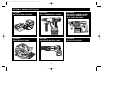
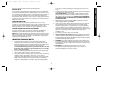
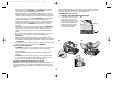
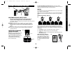
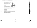
24 Volt InsMan 0162
10/22/02
8:55 AM
Page 1
INSTRUCTION MANUAL
24 VOLT CORDLESS TOOLS
MODELS: DW004 SDS ROTARY HAMMER
DW005 SDS ROTARY HAMMER WITH STOP ROTATION
DW006 DRILL / HAMMERDRILL
DW007 CIRCULAR SAW
DW008 RECIPROCATING SAW
DE0245 / DE0246 BATTERY CHARGER
24 Volt InsMan 0162
10/22/02
8:56 AM
Page 2
SECTION A: GENERAL SAFETY RULES
SECTION B:
BATTERIES AND CHARGERS
SECTION C:
DRILL / HAMMERDRILL DW006
SECTION D:
SDS ROTARY HAMMER DW004
SDS ROTARY HAMMER WITH
STOP ROTATION DW005
SECTION E:
CIRCULAR SAW DW007
SECTION F:
RECIPROCATING SAW DW008
SECTION G:
AFTER SALES SERVICE
2
24 Volt InsMan 0162
10/22/02
8:56 AM
Page 3
SAFETY INSTRUCTIONS
When using power tools, always observe the safety regulations applicable in your
country to reduce the risk of fire, electric shock and personal injury. Read the
following safety instructions before attempting to operate these products. Keep
these instructions in a safe place.
General
1.
2.
Keep work area clean. Cluttered areas and benches can cause accidents.
Consider work area environment. Do not expose power tools, including
chargers, to high humidity or rain. Keep work area well lit. Do not use power
tools, including all cordless tools and chargers, in the presence of flammable
liquids or gases.
3. Guard against electric shock. Prevent body contact with earthed surfaces
(e.g. pipes, radiators, cookers and refrigerators).
4. Keep children away. Do not let children come into contact with the tool or
extension cord. Keep all people away from the work area.
5. Extension cords for outdoor use. When the tool is used outdoors, always
use extension cords intended for outdoor use and marked accordingly.
6. Store idle tools. When not in use, power tools must be stored in a dry place
and locked up securely, out of the reach of children.
7. Dress properly. Do not wear loose clothing or jewellry. They can be caught in
moving parts. Preferably wear rubber gloves and non-slip footwear when
working outdoors. Wear protective hair covering to keep long hair out of the
way.
8. Wear safety goggles. Also use a face or dust mask in case the operations
produce dust or flying particles.
9. Be aware of maximum sound pressure. Take appropriate measures for
the protection of hearing if the sound pressure of 85dB(A) is exceeded.
10. Secure workpiece. Use clamps or a vice to hold the workpiece.
It is safer and it frees both hands to operate the tool.
11. Do not overreach. Keep proper footing and balance at all times.
12. Avoid unintentional starting. Do not carry the plugged-in tool with a finger
on the switch. Be sure that the switch is released when plugging in.
3
SECTION A: GENERAL SAFETY RULES
13. Stay alert. Watch what you are doing. Use common sense. Do not operate
the tool when you are tired.
14. Disconnect tool. Shut off power and wait for the tool to come to a complete
standstill before leaving it unattended. Unplug the tool when not in use, before
servicing or changing accessories.
15. Remove adjusting keys and wrenches. Always check that adjusting keys
and wrenches are removed from the tool before operating the tool.
16. Use appropriate tool. Do not force small tools or attachments to do the job
of a heavy-duty tool. The tool will do the job better and safer at the rate for
which it is intended. The use of any accessories or attachments other than the
ones recommended in this instruction manual may induce a risk of personal
injury.
17. Do not abuse cord. Never carry the tool by its cord or pull the cord to
disconnect it from the socket. Keep the cord away from heat, oil and sharp
edges.
18. Maintain tools with care. Keep tools in good condition and clean for better
and safer performance. Follow the instructions for maintenance and changing
accessories. Inspect tool cords at regular intervals and, if damaged, have them
repaired by an authorised DEWALT Repair Centre. Inspect extension cords
periodically and replace them if damaged. Keep all controls dry, clean and free
from oil and grease.
19. Check damaged parts. Before using the tool, carefully check it for damage
to ensure it will operate properly and perform its intended function. Check for
misalignment and seizure of moving parts, breakage of parts and any other
conditions that may affect its operation. Have damaged guards or other
defective parts repaired or replaced as instructed. Do not use the tool if switch
is defective. Have the switch replaced by an authorised DEWALT Repair Centre.
20. Have your tool repaired by an authorised DEWALT Repair Centre.
This power tool is in accordance with the relevant safety regulations. To avoid
danger, electric appliances must only be repaired by qualified technicians.
21. These tools are not intended for use by young children or infirm persons
without supervision. Young children should be supervised to ensure that they do
not play with these tools.
SECTION A: GENERAL SAFETY RULES
24 Volt InsMan 0162
10/22/02
8:56 AM
Page 4
•
SECTION B: BATTERY DE0240 & CHARGER DE0245 & DE0246
BATTERY PACKS
Important Safety Instructions for
Battery Packs.
Fig. B1
Your tool uses a 24.0 Volt DEWALT battery
pack. When ordering replacement battery
packs, be sure to include catalogue number
and voltage which is clearly marked on the
battery label (i.e., 24V DE0240).
The battery pack is not fully charged out of the kitbox. First read the safety
instructions below. Then follow charging notes and procedures.
• Do not incinerate the battery pack even if it is severely damaged or is
completely worn out. The battery pack can explode in a fire.
• A small leakage of liquid from the battery pack cells may occur under extreme
usage or temperature conditions. This does not indicate a failure. However, if
the outer seal is broken and this leakage gets on your skin:
a. Wash quickly with soap and water.
b. Neutralise with a mild acid such as lemon juice or vinegar.
c. If battery liquid gets into your eyes, flush them with clean water for a
minimum of 10 minutes and seek immediate medical attention. (Medical
note: The liquid is 25-35% solution of potassium hydroxide.)
• Never attempt to open the battery pack for any reason. If the plastic housing of
the battery pack breaks or cracks, immediately discontinue use and do not
recharge.
• Do not carry extra battery packs in aprons, pockets, or tool boxes along with
other metal objects. Battery pack could be short circuited causing damage to
the battery pack and possibly causing severe burns or fire.
• Charge the battery packs only in DeWALT chargers.
• NOTE: Review and observe all the safety instructions in the charger
instruction section of this manual.
• NOTE: The battery cells in your battery pack are the nickel-cadmium (NiCad)
type. Cadmium is considered to be a toxic material by the Environmental
Protection Agency. Before disposing of damaged or worn out NiCad battery
packs, check with your government Environmental Protection Agency to find
out about special restrictions on the disposal of these battery packs or return
them to a DeWALT authorised repair centre for recycling.
•
•
The battery pack should not be subjected to wet conditions. Where a battery
pack has become wet the exterior of the battery pack should be dried with a
dry cloth prior to storage or use. If the battery pack has been fully submerged
the pack should be taken to a service centre to be opened and dried. The
battery pack should not be subjected to any external heating (ie heater or oven)
to dry the battery pack. Under no circumstances should a wet or damp
battery pack be placed in the battery charger as there is line
voltage present at the battery charger terminals.
The battery pack should be handled with a degree of care and should not be
dropped or be subjected to severe impacts. A cracked or fractured battery
case should NEVER be placed in a charger to be recharged. In some cases
high voltage can be measured at the outside of a cracked battery pack and
electrocution is then a possibility.
FAILURE TO OBSERVE THE CARE GUIDELINES OUTLINED
ABOVE CAN BE CONSIDERED ABUSE AND MAY VOID ANY
WARRANTY CLAIM
Important Information on Battery Packs
The battery cells contained in the battery packs supplied with this tool are NiCad
cells and their life will greatly depend on how they are cared for by you the operator.
The following details will assist you to obtain the maximum life from your battery
packs.
Temperature
•
Battery packs should be kept as cool as is practicable whilst in use, charging
and also when in storage. Battery packs should not be left in areas where high
temperatures are experienced, including cars on hot days, small sheds in
summer, or work areas with ambient temperatures above 35°C.
Usage
•
•
•
4
During use, do not overload the tool. If the battery pack is getting hot then
generally the tool is being overloaded. Overloading can be prevented by
ensuring the cutting tool is sharp, by ensuring the cutting tool is not too large for
the powertool and by not forcing the tool into the work piece.
Where a battery pack has become hot in the tool, remove the battery pack from
the tool and allow the battery to cool as quickly as possible and then re-charge,
unless the battery pack is a fan-cooled unit. If your battery pack is a fan cooled
unit the fastest and best way to cool it down is to immediately put it into the
matching charger and turn it on.
Never run a battery down to the point where the tool stops. DeWALT power tool
battery packs do not suffer from battery memory effect so there is no
24 Volt InsMan 0162
10/22/02
8:56 AM
Page 5
•
Storage
•
•
•
•
Always try and recharge the battery prior to storage, even when the battery will
only be stored for a few days. If a battery pack is going to be stored for more
than 2 weeks do not leave it in the battery charger. The proper way to store the
battery pack for extended periods is to charge the pack for approximately 8
hours and then place the pack in a cool environment away from the charger.
Batteries should be charged overnight (or for approximately 8 hours) at least
once a week or after every 10-15 charges. This equalises or balances out the
battery pack for better runtime and life.
FAILURE TO OBSERVE THE CARE GUIDELINES OUTLINED
ABOVE CAN BE CONSIDERED ABUSE AND MAY VOID ANY
WARRANTY CLAIM
•
•
•
BATTERY CHARGERS
•
Important Safety Instructions for Battery Chargers
•
•
This manual contains important safety and operating instructions.
• Before using charger read all instructions and cautionary markings on (1)
charger, (2) battery pack, and (3) product using battery pack.
• DANGER: Line voltage present at charging terminals. Do not probe with
conductive objects. Danger of electric shock or electrocution.
• DANGER: If battery case is cracked or damaged, do not insert into charger.
Danger of electric shock or electrocution.
• The charger and battery pack are specifically designed to work together. DO
NOT attempt to charge the battery pack with any chargers other than the ones
in this manual.
• Do not expose charger to high humidity, rain or snow.
• These chargers are not intended for any uses other than charging DEWALT
rechargeable batteries. Any other uses may result in risk of fire, electric shock
and electrocution.
• To reduce risk of damage to electric plug and cord, pull by plug rather than cord
when disconnecting charger.
• Make sure cord is located so that it will not be stepped on, tripped over, or
•
•
•
•
otherwise subjected to damage or stress.
An extension cord should not be used unless absolutely necessary. Use of
improper extension cord could result in risk of fire, electric shock or
electrocution.
The charger is ventilated through slots in the top and the bottom of the housing.
Do not place any object on top of the charger or place the charger on a soft
surface that might block the ventilation slots and result in excessive internal
heat. Place the charger in a position away from any heat source. In the case of
the DE0246, which is fan assisted, all ventilation slots must be kept clear.
Do not operate charger with damaged cord or plug - have them replaced
immediately at an authorised DEWALT Service Centre.
Do not operate charger if it has received a sharp blow, been dropped, or
otherwise damaged in any way; take it to an authorised DEWALT Service
Centre.
Do not disassemble charger; take it to an authorised DEWALT Service Centre
when service or repair is required. Incorrect reassembly may result in a risk of
electric shock, electrocution or fire.
To reduce risk of electric shock, unplug charger from outlet before att-emptying
any cleaning. Removing the battery pack will not reduce this risk.
NEVER attempt to connect two chargers together.
DO NOT store or use the tool or battery pack in locations where the
temperature may reach or exceed 40°C (105°F) (such as outside sheds or metal
buildings in summer).
The charger is designed to operate on standard household electrical power,
240V AC 50Hz.. Do not attempt to use it on any other voltage. Check to ensure
mains voltage agrees with voltage on plate of charger.
Replacement of the supply cord. If the supply cord is damaged, it must be
replaced by the manufacturer or an authorised DEWALT Service Centre in order
to avoid a hazard.
This appliance (charger and tool) is not intended for use by young children or
infirm persons without supervision.
Young children should be supervised to ensure that they do not play with this
appliance (charger and tool).
THE CHARGER SUPPLIED
Your 24V tool is supplied with either a DE0245 or a DE0246 24 volt battery charger.
Both chargers operate in a similar manner but are fitted with a number of different
5
SECTION B: BATTERY DE0240 AND CHARGER DE0245 & DE0246
advantage in running the battery flat. At the point where the tool no longer
performs the task which is normally performed the battery pack should be
removed from the power tool, allowed to cool to room temperature and then
placed in the charger to re-charge
24 Volt InsMan 0162
10/22/02
8:56 AM
Page 6
features. The DE0245 charger is fitted with a manual tune-up mode whereas the
DE0246 is fitted with an automatic tune-up mode. Also, the DE0246 charger is fitted
with a cooling fan to assist the cooling of the battery cells when the battery pack is
fitted to the charger.
Your charger is designed to use standard 240 volt AC, 50 Hz power. Do not use DC or
any other voltage. Charging time is approximately one hour.
The DE0245 charger is fitted with a manual Tune-Up mode cycle which is initiated by
the operator pushing the small button at the front of the charger marked "Tune-Up
Mode."
The DE0246 is fitted with an auto Tune-Up mode cycle where at the completion of
the normal charging cycle if the battery is left in the charger, the tune up mode cycle
begins.
Charging Procedure (DE0245 & DE0246)
For DE0245 Manual Tune-Up
The DE0246 charger is fitted with an internal cooling fan that provides rapid cooling of the
cells in the battery pack. The fan operation is automatic and will operate for a short time
when the charger is initially plugged in and turned on. The fan will also operate while the
charging process is underway when a battery is inserted.
This feature is of great benefit where the battery pack has become hot during heavy
applications in the tool and the pack is inserted to the charger to both cool the pack
and either partially or fully charge the pack.
To fully optimise both the life and performance of the battery pack, remove the
battery pack from the tool as soon as possible and insert into the charger so as to
allow the internal fan to cool the individual cells.
WARNING: On the DE0246, the fan may blow debris from vent area at any time.
Keep your face and eyes well above the outlet vent area. Depending on the
environment where the charger is being used it may be necessary to wear eye
protection.
1. Plug the charger into an appropriate outlet.
(On the DE0246 the fan will operate initially for up to 30 sec)
2. Insert the battery pack into the charger (refer figure B1). Be sure the pack is fully
seated in the charger. The red (charging) light will blink continuously indicating
that the charging process has started. On the DE0246 the fan will operate and
remain "On" during the main charging cycle.
3. The completion of charge will be indicated by the red light remaining ON
continuously. The pack is fully charged and may be used at this time or left in
the charger.
1.
Using Tune-Up mode
CHARGE INDICATORS
Using Tune-Up mode will equalise or balance the individual cells in the battery pack
at its peak capacity. This cycle takes up to 8 hours to complete. Battery packs should
be tuned up weekly or after 10 to 15 charge/discharge cycles or whenever the pack
no longer delivers the same amount of work.
Both the DE0245 and the DE0246 are fitted with a Tune-Up mode feature.
HOT/ COLD PACK DELAY:
2.
3.
4.
To tune up your battery pack, place the battery in the charger as usual. The red
light will blink continuously indicating that the charge cycle has started.
The Tune-Up button may be pressed at any time after the charge has started.
The red light will stop blinking momentarily, blink 3 times and then resume
blinking continuously. The charger is now giving your batteries a tune-up.
When the charge cycle has completed, the light will stay on continuously. The
pack is fully charged and may be used at this time or left in the charger.
If you select Tune-Up and then change your mind, remove the battery from the
charger. After 5 seconds, insert the battery into the charger. Then normal
charge cycle will commence. To tune up your battery pack, place the battery in
the charger as usual. The red light will blink continuously indicating the charge
cycle has started.
For DE0246 Auto Tune-Up
To tune up your battery pack, place the battery in the charger as usual. The red light will
blink continuously indicating that the charge cycle has started.
When the battery is fully charged the red light will remain on, and the tune up cycle
will begin. For the full tune up process, leave the battery pack in the charger for a
further 7 - 8 hours. Please note that the battery pack can be used during the tune up
cycle but when the battery is replaced in the charger, the charging cycle will start
again followed by the tune up cycle where the battery should stay for the full 7 - 8
hours.
During the tune up cycle the red indicator light will remain "ON" continuously.
When the charger detects a battery that is excessively hot or excessively cold, it
automatically starts a Hot/Cold Pack Delay, suspending charging until the battery
temperature has normalised. After this happens, the charger automatically switches
to the Pack Charging mode. This feature ensures maximum battery life. The red light
6
24 Volt InsMan 0162
10/22/02
8:56 AM
Page 7
REPLACE PACK:
These chargers are designed to detect certain problems that can arise with battery
packs which would be indicated by the red light flashing at a fast rate. If this occurs,
re-insert battery pack. If problem persists, try a different battery pack to determine if
the charger is OK. If the new battery charges correctly, then the original pack is
defective and should be returned to a service centre for recycling. If the new battery
pack gives the same trouble indication as the original, have the charger tested at an
Authorised Service Centre.
PROBLEM POWER LINE:
When these chargers are used with some portable power sources such as
generators or sources that convert DC to AC, the chargers may temporarily suspend
operation, flashing the red light with two fast blinks followed by a pause. This
indicates the power source is out of limits. Your power supply may need service.
LEAVING THE BATTERY PACK IN THE CHARGER
The charger and battery pack can be left connected with the red light glowing
indefinitely. The charger will keep the battery pack fresh and fully charged.
NOTE: A battery pack will slowly lose its charge when kept out of the charger. If the
battery pack has not been kept on maintenance charge, it may need to be recharged
before use. A battery pack may also slowly lose its charge if left in a charger that is
not plugged into an appropriate AC source.
IMPORTANT CHARGING NOTES
1.
2.
3.
Longest life and best performance can be obtained if the battery pack is
charged when the air temperature is between 18°C and 24°C (65°-75°F). DO
NOT charge the battery pack in an air temperature below +4.5°C (+40°F). This is
important and will prevent serious damage to the battery pack. It is
recommended the battery pack is cycled on the tune-up mode and
the battery is left on charge for approximately 8 hours on a weekly
basis or every 10-15 charges.
The charger and battery pack may become warm to the touch while charging.
This is a normal condition, and does not indicate a problem.
If the battery pack does not charge properly - (1) Check power at receptacle by
plugging in a lamp or other appliance. (2) Check to see if receptacle is
connected to a light switch which turns power off when you turn out the lights.
(3) Move charger and battery pack to a location where the surrounding air
temperature is approximately 18° - 24°C (65°F - 75°F). (4) If charging problems
7
SECTION A. SAFETY INSTRUCTIONS
persist, take or send the tool, battery pack and charger to your local service
centre.
4. The battery pack should be recharged when it fails to produce sufficient power
on jobs which were easily done previously.
DO NOT CONTINUE to use under these conditions. Follow the charging
procedure. You may also charge a partially used pack whenever you desire
with no adverse effect on the battery pack. DO NOT FULLY DISCHARGE
THE BATTERY PACK AS THIS CAN CAUSE SEVERE DAMAGE TO
THE BATTERY PACK.
5. DEWALT battery packs that are labelled “NiMH” should only be used with
chargers labelled “NiMH” or NiCd/ NiMH”.
6. Under certain conditions, with the charger plugged into the power supply, the
exposed charging contacts inside the charger can be shorted by foreign
material. Foreign materials of a conductive nature such as, but not limited to,
steel wool, aluminium foil, or any build up of metallic particles should be kept
away from charger activities. Always unplug the charger from the power supply
when there is no battery pack in the cavity. Unplug the charger before
attempting to clean.
7. Do not immerse charger in water or any other liquid.
8. Air Cooled batteries and chargers. Battery packs with the air cooling feature
should be removed from the tool and placed into the DE0246 charger as soon as
practical to rapidly cool the battery cells within the charger. This will assist greatly
to optimise both battery life and performance.
9. WARNING: Do not allow any liquid to get inside the charger. Electric shock
may result. To facilitate the cooling of the battery pack after use, avoid placing
the battery pack or charger in a warm environment such as a metal shed, or an
uninsulated trailer.
10. CAUTION: Never attempt to open the battery pack for any reason.
If the plastic housing of the battery pack breaks or cracks, return to an
authorised DeWALT Service Centre for recycling.
flashes long, then short while in the Hot/ Cold Pack Delay mode.
24 Volt InsMan 0162
10/22/02
8:56 AM
Page 8
C2
NOTE: Make sure your battery pack is fully
charged. To install the battery pack into the
tool, lock the trigger switch (See Forward/Reverse
Control Button), align the base of the tool with
notches inside the tool’s handle and slide the
battery pack firmly into the handle until you hear the
lock snap into place.
A
To remove the battery pack from the tool, lock
the trigger switch, slide the release button (A)
away from the battery pack (B) and the battery
B
may be removed from the tool handle. Insert it into
the charger as described in the charging section of
this manual.
CAUTION: DO NOT TOUCH ANY METAL
PARTS OF THE TOOL when drilling or driving
into walls, floors or wherever live electrical wires
may be encountered! Hold the tool only by insulated grasping surfaces to prevent
electric shock if you drill or drive into a live wire.
WARNING: Use of this tool can generate dust containing chemicals known to
cause cancer, birth defects or other reproductive harm. Use appropriate respiratory
protection.
C
D
B
A
Additional Safety Rules for Hammer Drills
Hold tool by insulated gripping surfaces when performing an operation where the
cutting tool may contact hidden wiring. Contact with a ‘live’ wire will make exposed
metal parts of the tool ‘live’ and shock the operator.
Wear safety goggles or other eye protection. Hammering and drilling operations
cause chips to fly. Flying particles can cause permanent eye damage.
Wear ear protectors when hammering for extended periods of time. Temporary
hearing loss or serious ear drum damage may result from high sound levels
generated by hammer drilling.
Always use the side handle supplied with the tool. Keep a firm grip on the tool at all
times. Do not attempt to operate this tool without holding it with both hands.
Do not overreach while operating the tool. Maintain a balanced working stance at all
times. When necessary, use only properly positioned, safe, platforms and
scaffolding. WORK SAFE.
Hammer bits and tools get hot during operation. Wear gloves when touching them.
Motor
Your DEWALT tool is powered by a DEWALT-built motor. Be sure your power supply
battery agrees with the nameplate markings.
All DEWALT tools are factory tested; if this tool does not operate, check your battery
pack.
Side Handle Fig. C1 (A)
CAUTION: Always use side handle when provided and hold hammerdrill with both
hands. A side handle is supplied with this hammerdrill. It clamps to the front of the
gear case as shown in Figure C1 and can be rotated 360° to permit right or left hand
use.
Variable Speed Switch Fig. C1 (B)
To turn the tool on, squeeze the trigger switch. To turn the tool off, release the trigger
switch. Your tool is equipped with a brake. The chuck will stop as soon as the trigger
switch is fully released.
7
SECTION C: 13mm CORDLESS HAMMERDRILL DW006
Installing and Removing the Battery
Pack (Fig. C2)
SECTION C: 13MM CORDLESS HAMMER DRILL
DW006
C1
E
24 Volt InsMan 0162
10/22/02
8:56 AM
Page 9
The variable speed switch enables you to select the best speed for a particular
application. The farther you squeeze the trigger, the faster the tool will operate. Use
lower speeds for starting holes without a centrepunch, drilling in metals or plastics,
driving screws and drilling ceramics. For maximum tool life, use variable speed only
for starting holes or fasteners.
NOTE: Continuous use in variable speed range is not recommended.
It may damage the switch and should be avoided.
NOTE: Do not change gears when the tool is running. If you are having trouble
shifting gears, make sure that the dual range gear button is either completely pushed
forward or completely pushed back.
OPERATION
DRILLING
1.
Forward/Reverse Control Button Fig. C1 (C)
A forward/reverse control button determines the direction of chuck rotation and also
serves as a lock off button. To select forward rotation, release the trigger switch and
depress the forward/reverse control button on the right side of the tool. To select
reverse, depress the forward/reverse control button on the right side of the tool. The
centre position of the control button locks the tool in the off position. When changing
the position of the control button, be sure the trigger is released. NOTE: The first
time the tool is run after changing the direction of rotation, you may hear a click on
start up. This is normal and does not indicate a problem.
2.
Hammer/Drill Selector Fig. C1 (D)
4.
3.
To switch the tool from the drilling mode to the hammering mode (or vice-versa) rotate
the knob to the applicable symbol shown. For straight drilling, rotate to the drill symbol.
For hammering, rotate to the hammer symbol (As shown in figure C1 (D)). NOTE: The
selector must be in either drill, or hammer/drill mode at all times. These are no operable
positions between the two.
5.
6.
Dual Range Gearing Fig. C3
The dual range feature of your drill allows you to shift gears for greater versatility. To
select the low speed, high torque setting (position 1), turn the tool off and permit to
stop. Slide the button forward
C3
towards the chuck. To select the
high speed, low torque setting
(position 2), turn the tool off and
permit to stop. Slide the button
A
Position 1
back (away from chuck).
7.
8.
9.
Position 2
8
Always lock the trigger switch and remove the battery pack before attaching or
changing bits or accessories.
Use sharp drill bits only. For WOOD, use the low speed setting and twist drill bits,
spade bits, power auger bits, or hole saws. For METAL, use the low speed
setting and steel twist drill bits or hole saws. For MASONRY, such as brick,
cement, cinder block, etc., use high speed setting and carbide-tipped bits rated
for percussion drilling.
Be sure the material to be drilled is anchored or clamped firmly. If drilling thin
material, use a wood “back-up” block to prevent damage to the material.
Always apply pressure in a straight line with the bit. Use enough pressure to
keep drill biting, but do not push hard enough to stall the motor or deflect the bit.
Hold tool firmly to control the twisting action of the drill.
IF DRILL STALLS, it is usually because it is being overloaded or improperly
used. RELEASE TRIGGER IMMEDIATELY, remove drill bit from work, and
determine cause of stalling. DO NOT CLICK TRIGGER OFF AND ON IN
AN ATTEMPT TO START A STALLED DRILL – THIS CAN DAMAGE
THE DRILL.
To minimise the stalling or breaking through the material, reduce pressure on drill
and ease the bit through the last fractional part of the material.
Keep the motor running when pulling the bit back out of a drilled hole. This will
help prevent jamming.
With variable speed drills there is no need to centre punch the point to be
drilled. Use a slow speed to start the hole and accelerate by squeezing the
trigger harder when the hole is deep enough to drill without the bit skipping out.
8:56 AM
Page 10
C5
USE ONLY in the ‘low speed’ gear range. Start drilling with slow speed and increase
to full power while applying firm pressure on the tool. A smooth even flow of metal
chips indicates the proper drilling rate. Use a cutting lubricant when drilling metals.
The exceptions are cast iron and brass which should be drilled dry.
NOTE: Large (8 mm (5/16”) to 13 mm (1/2”)) holes in steel can be made easier if a
pilot hole (4mm (5/32”) to 5mm (3/16”)) is drilled first.
C6
4
5
5
3
DRILLING IN WOOD
USE ONLY in the ‘low speed’ gear range. Start drilling with slow speed and increase
to full power while applying firm pressure on the tool. Holes in wood can be made
with the same twist drills used for metal. These bits may overheat unless pulled out
frequently to clear chips from the flutes. Work that is apt to splinter should be backed
up with a block of wood.
Chuck Removal
Always wear eye protection.
Slide the dual range gear button to position 1. Tighten the chuck around the shorter
end of a hex key (not supplied) of 10mm (3/8”) or greater size. Using a wooden mallet
or similar object, strike the longer end in the clockwise direction, as shown in Fig. C5.
This will loosen the screw inside the chuck.
Open chuck jaws fully, insert screwdriver (or Torx tool if required) into front of chuck
between jaws to engage screw head. Remove screw by turning clockwise (lefthand thread). Place hex key in chuck and tighten. Using a wooden mallet or similar
object, strike key sharply in the counterclockwise direction. This will loosen the
chuck so that it can be unscrewed by hand.
DRILLING IN MASONRY
Use only in the ‘high speed’ gear range. When drilling in masonry, use carbide tipped
bits rated for percussion drilling and be certain that the bit is sharp. Ensure that the
hammer mode is selected. Use a constant and firm force on the tool to drill most
effectively. A smooth, even flow of dust indicates the proper drilling rate.
KEYLESS CHUCK
SPINDLE LOCK
Open chuck jaws by turning the collar
with your fingers and inserting the
shank of the bit about 19 mm (3/4”) into
the chuck. Tighten the follower
clockwise while depressing the spindle
lock button (Fig. C4 (A)) on the right side
of the tool housing. To release a bit, turn
the collar counter-clockwise while
depressing the spindle lock button.
CAUTION: Do not depress lock
button while operating drill or while the
chuck is moving. Always lock off trigger
switch when changing accessories.
C4
Chuck Installation
A
Screw the chuck on by hand as far as it will go and insert screw (LH thread). Tighten
the chuck around the shorter end of a 10 mm (3/8) or larger hex key (not supplied)
strike the longer end in the clockwise direction with a wooden mallet, as shown in
Fig C6. Tighten the screw by turning in a counterclockwise direction.
9
SECTION C: 13mm CORDLESS HAMMERDRILL DW006
DRILLING IN METAL
4
10/22/02
3
24 Volt InsMan 0162
24 Volt InsMan 0162
10/22/02
8:56 AM
Page 11
electric shock if you drill or drive into a live wire.
SECTION D: 22MM CORDLESS ROTARY HAMMER DW004
22MM CORDLESS ROTARY HAMMER
WITH STOP ROTATION DW005
Motor
Your DEWALT tool is powered by a DEWALT-built motor. Be sure your power supply
battery agrees with the nameplate markings.
All DEWALT tools are factory tested; if this tool does not operate, check your battery
pack.
D
D1
Installing and Removing the Battery Pack (Fig. D1)
NOTE: Make sure your battery pack is fully charged.
To install the battery pack into the tool, centre the lock button (Pic D1 (C)) to
disable the trigger switch (See section Forward and Reverse button), align the front
of the battery with the notches inside the tool’s body and slide the battery pack firmly
into place until you hear the lock slide into place.
To remove the battery pack from the tool, depress the release buttons (E) on
both sides, remove the battery pack (F). Insert it into the charger as described in the
charger section of the manual.
C
A
B
E
F
Side Handle (Fig. D1 (A))
ADDITIONAL SAFETY RULES FOR ROTARY HAMMERS
CAUTION: Always use side handle and hold rotary hammer with both hands. It
clamps to the front of the gear case as shown in Figure D1 and can be rotated 360˚
to permit right or left hand use.
•
Variable Speed Switch (Fig. D1 (B))
•
•
•
•
•
•
Hold tool by insulated gripping surfaces when performing an operation where
the cutting tool may contact hidden wiring or its own cord. Contact with a ‘live’
wire will make exposed metal parts of the tool ‘live’ and shock the operator.
Wear safety goggles or other eye protection. Hammering and drilling operations
cause chips to fly. Flying particles can cause permanent eye damage.
Wear ear protectors when hammering for extended periods of time. Temporary
hearing loss or serious ear drum damage may result from the high sound levels
generated by hammer drilling.
Always use the side handle supplied with the tool. Keep a firm grip on the tool at
all times. Do not attempt to operate this tool without holding it with both hands.
Do not overreach while operating the tool. Maintain a balanced working stance
at all times. When necessary, use only properly positioned, safe, platforms and
scaffolding. WORK SAFE.
Hammer bits and tools get hot during operation. Wear gloves when touching
them.
CAUTION: DO NOT TOUCH ANY METAL PARTS OF THE TOOL
when drilling or driving into walls, floors or wherever live electrical wires may
be encountered! Hold the tool only by insulated grasping surfaces to prevent
To turn the tool on, squeeze the trigger switch. To turn the tool off, release the trigger
switch. Your tool is equipped with a brake. The chuck will stop as soon as the trigger
switch is fully released.
The variable speed switch enables you to select the best speed for a particular
application. The farther you squeeze the trigger, the faster the tool will operate. Use
lower speeds for starting holes without a centrepunch, drilling in metals or plastics,
driving screws and drilling ceramics. For maximum tool life, use variable speed only
for starting holes or fasteners.
NOTE: Continuous use in variable speed range is not recommended.
It may damage the switch and should be avoided.
Forward/Reverse Control Button (Fig D1 (C))
A forward/reverse control button determines the direction of rotation and also
serves as a lock off button. To select forward rotation, release the trigger switch and
depress the forward/reverse control button on the right side of the tool. To select
reverse, depress the forward/reverse control button on the left side of the tool. The
centre position of the control button locks the tool in the off position. When changing
the position of the control button, be sure the trigger is released and the tool has
11
24 Volt InsMan 0162
10/22/02
8:56 AM
Page 12
1.
2.
DW004 Hammer Drilling/Rotary Drilling Selector (Fig. D1 (D) D2)
To switch the tool from the drilling mode to the hammering mode (or vice-versa)
rotate the lever to the applicable symbol shown. For straight drilling, align the lever
with the drill bit symbol (B) as shown.
For hammer, align the lever with the
A
B
D2 DW004
hammerdrill symbol (A). NOTE: The
selector must be in either drill, or
hammerdrill mode at all times. There
are no operable positions between the
two.
3.
4.
5.
6.
DW005 Hammer Drilling/Rotary
Drilling/Hammer Only with
Stop Rotation Selector (Fig. D1
(D) D3)
7.
For hammer drilling and rotary drilling
follow the instructions above for the DW004. For hammer only with stop rotation for
light chipping, chiselling and light demolition work, rotate the lever to hammer
symbol (C). When using the DW005 in
A
C
hammer position with stop rotation for D3 DW005 B
light demolition work, the
forward/reverse selector should be in
the Forward position.
8.
9.
Always lock the trigger switch and remove the battery pack before attaching or
changing bits or accessories.
Use sharp drill bits only. For WOOD, use the low speed setting and twist drill
bits, spade bits, power auger bits, or hole saws. For METAL, use the low speed
setting and steel twist drill bits or hole saws. For MASONRY, such as brick,
cement, cinder block, etc., use carbide-tipped bits rated for percussion drilling.
Be sure the material to be drilled is anchored or clamped firmly.
If drilling thin material, use a wood ‘back-up’ block to prevent damage to the
material.
Always apply pressure in a straight line with the bit. Use enough pressure to
keep drill biting, but do not push hard enough to stall the motor or deflect the bit.
Hold tool firmly to control the twisting action of the drill.
IF DRILL STALLS, it is usually because it is being overloaded or improperly
used. RELEASE TRIGGER IMMEDIATELY, remove drill bit from work, and
determine cause of stalling. DO NOT CLICK TRIGGER OFF AND ON IN
AN ATTEMPT TO START A STALLED DRILL – THIS CAN DAMAGE
THE DRILL.
To minimise the stalling or breaking through the material, reduce pressure on
drill and ease the bit through the last fractional part of the material.
Keep the motor running when pulling the bit back out of a drilled hole. This will
help prevent jamming.
With variable speed drills there is no need to centre punch the point to be
drilled. Use a slow speed to start the hole and accelerate by squeezing the
trigger harder when the hole is deep enough to drill without the bit skipping out.
DRILLING IN METAL
To Rotate or Align the Chisel
Bit (DW005 only)
Start drilling with slow speed and increase to full power while applying firm pressure
on the tool. A smooth even flow of metal chips indicates the proper drilling rate. Use
a cutting lubricant when drilling metals. The exceptions are cast iron and brass
which should be drilled dry.
NOTE: Large (8mm (5/16”) to 12mm (1/2”)) holes in steel can be made easier if a
pilot hole (4mm (5/32”) to 5mm (3/16”)) is drilled first.
If it is necessary to rotate the chisel bit
to obtain a more comfortable working
position, position the forward/reverse
control button to the centre lock-off
position. Move the drill mode selector
lever to the hammerdrill position. Rotate the chisel bit to the required position with
your hand. Move the drill mode selector back to the hammer position and begin
chiselling.
DRILLING IN WOOD
OPERATION
Start drilling with slow speed and increase to full power while applying firm pressure
on the tool. Holes in wood can be made with the same twist drills used for metal.
These bits may overheat unless pulled out frequently to clear chips from the flutes.
Work that is apt to splinter should be backed up with a block of wood.
DRILLING
DRILLING IN MASONRY
12
SECTION D: 22MM CORDLESS ROTARY HAMMER DW004/DW005
stopped.
NOTE: The first time the tool is run after changing the direction of rotation, you may
hear a click on start up. This is normal and does not indicate a problem.
24 Volt InsMan 0162
10/22/02
8:56 AM
Page 13
When drilling in masonry, use carbide tipped bits rated for percussion drilling. Be
certain that the bit is sharp. Ensure that the hammer mode is selected. Use a
constant and firm force on the tool to drill most effectively. A smooth, even flow of
dust indicates the proper drilling rate.
D5
Chipping and Chiselling
Select the hammering only mode. Insert and SDS-plus® chisel and check that it is
properly locked. Adjust the side handle as required. Proceed as described for
hammer drilling.It may be necessary to briefly run the motor after having changed
from chiselling to rotary modes in order to align the gears..
NOTE: Select Forward direction when chipping and chiselling.
To fit the adaptor to the drill, follow the section ‘SDS Chuck, (Fig. D4)’.
To fit the chuck to adaptor, screw the chuck onto the adaptor in a clockwise
direction and ensure the chuck is tight on the adaptor. Open the jaws of the chuck
fully and fit the small lock screw down the centre of the chuck (note left hand
thread). Ensure the lock screw is tight by rotating the screw in an anti-clockwise
direction. (FIG. D5)
To remove the chuck, reverse the above procedure.
NOTE: On models DW004K2C and DW005K2C, both the chuck adaptor and 3 jaw
chuck are supplied with the drill. For other models, the chuck adaptor and 3 jaw
chuck are available as accessories.
SDS Chuck (Fig. D4)
To insert bit, insert shank of bit about 19mm (3/4”) into chuck and twist the bit until it
clicks into place. The bit will be securely held.
To release bit, pull the collar back and remove the bit.
3 Jaw Chuck Adaptor (FIG. D5)
A chuck adaptor is available for the DW004 rotary hammer drill. The adaptor enables
a standard keyless or keyed chuck to be fitted so straight shank drill bits can be
used. The chuck adaptor should not be
D4
used in the hammer or hammerdrill
position. This adaptor is designed to
function with non-hammer applications.
ACCESSORIES
Recommended accessories for use with your tool are available at extra cost from
your distributor or local service centre.
CAUTION: The use of any non-recommended accessory may be hazardous.
MAXIMUM RECOMMENDED CAPACITIES (DW004)
R.P.M.
B.P.M.
BITS, METAL DRILLING
WOOD, FLAT BORING
BITS, MASONRY DRILLING
13
0-1,150
0-5,800
13mm (1/2”)
38mm (1 1/2”)
22mm (7/8”) bit –
Concrete, brick, block
24 Volt InsMan 0162
10/22/02
8:56 AM
Page 14
E1
Lock OFF
Button
Trigger
Switch
•
•
Bevel
Quadrant
•
•
Retracting
Lever
Shoe
Quadrant
Lever or Knob
•
ADDITIONAL SAFETY INSTRUCTIONS FOR
CIRCULAR SAWS
•
DANGER! Keep hands away from cutting area and blade. Keep your second hand
on auxiliary handle, or motor housing. If both hands are holding the saw, they cannot
be cut by the blade.
• Keep your body positioned to either side of the saw blade, but not in line with
the saw blade. KICKBACK could cause the saw to jump backwards. (See
‘Causes and Operator Prevention of Kickback.’)
• Do not reach underneath the work. The guard can not protect you from the
blade below the work.
• Check lower guard for proper closing before each use. Do not operate saw if
lower guard does not move freely and close instantly. Never clamp or tie the
lower guard into the open position. If saw is accidentally dropped, the lower
guard may be bent. Raise the lower guard with the Retracting Handle and make
sure it moves freely and does not touch the blade or any other part, at all angles
and depths of cut.
• Check the operation and condition of the lower guard spring. If the guard and
•
the spring are not operating properly, they must be serviced before use. Lower
guard may operate sluggishly due to damaged parts, gummy deposits, or a
build-up of debris.
Lower guard should be retracted manually only for special cuts such as ‘Pocket
Cuts’ and ‘Compound Cuts.’ Raise lower guard by Retracting Handle. As soon
as blade enters the material, lower guard must be released. For all other
sawing, the lower guard should operate automatically.
Always observe that the lower guard is covering the blade before placing saw
down on bench or floor. An unprotected, coasting blade will cause the saw to
walk backwards, cutting whatever is in its path. Be aware of the time it takes
for the blade to stop after switch is released.
NEVER hold piece being cut in your hands or across your leg. It is important to
support the work properly to minimise body exposure, blade binding, or loss of
control.
Hold tool by insulated gripping surfaces when performing an operation where
the cutting tool may contact hidden wiring. Contact with a ‘live’ wire will also
make exposed metal parts of the tool ‘live’ and shock the operator.
When ripping, always use a rip fence or straight edge guide. This improves the
accuracy of cut and reduces the chance for blade binding.
Always use blades with correct size and shape (diamond vs. round) arbor
holes. Blades that do not match the mounting hardware of the saw will run
eccentrically, causing loss of control.
Never use damaged or incorrect blade washers or bolts. The blade washers
and bolt were specially designed for your saw, for optimum performance and
safety of operation.
Causes and Operator Prevention of Kickback
•
•
•
•
14
KICKBACK is a sudden reaction to a pinched, bound or misaligned saw blade,
causing an uncontrolled saw to lift up and out of the workpiece toward the
operator.
When the blade is pinched or bound tightly by the kerf closing down, the blade
stalls and the motor reaction drives the unit rapidly back toward the operator.
If the blade becomes twisted or misaligned in the cut, the teeth at the back
edge of the blade can dig into the top surface of the wood causing the blade to
climb out of the kerf and jump back toward the operator.
KICKBACK is the result of tool misuse and/or incorrect operating procedures
or conditions and can be avoided by taking proper precautions as given below:
SECTION E: CORDLESS CIRCULAR SAW DW007
SECTION E: CORDLESS CIRCULAR SAW DW007
24 Volt InsMan 0162
•
•
•
•
•
•
•
10/22/02
8:56 AM
Page 15
Maintain a firm grip with both hands on the saw and position your body and
arm to allow you to resist KICKBACK forces. KICKBACK forces can be
controlled by the operator, if proper precautions are taken.
When blade is binding, or when interrupting a cut for any reason, release the
trigger and hold the saw motionless in the material until the blade comes to a
complete stop. Never attempt to remove the saw from the work or pull the saw
backward while the blade is in motion or KICKBACK may occur. Investigate
and take corrective actions to eliminate the cause of blade binding.
When restarting a saw in the workpiece, centre the saw blade in the kerf and
check that the saw teeth are not engaged into the material. If saw blade is
binding, it may walk up or KICKBACK from the workpiece as the saw is
restarted.
Support large panels to minimise the risk of blade pinching and KICKBACK.
Large panels tend to sag under their own weight. Support must be placed
under the panel on both sides, near the line of cut and near the edge of the
panel.
Do not use dull or damaged blades. Unsharpened or improperly set blades
produce narrow kerf causing excessive friction, blade binding, and
KICKBACK.
Blade depth and bevel adjustment locking levers must be tight and secure
before making cut. If blade adjustment shifts while cutting, it may cause binding
and KICKBACK.
Use extra caution when making a ‘Pocket Cut’ into existing walls or other blind areas.
The protruding blade may cut objects that can cause KICKBACK.
To remove the battery pack from the tool, slide the release button (A) away from the
battery pack (B) and the battery may be removed from the tool handle. Insert it into
the charger as described in the charger section of this manual.
Changing Blades (Fig. E2 & E3)
1.
2.
TURN OFF TOOL AND REMOVE BATTERY PACK.
To attach blade, retract lower blade
E1
guard and place blade over the
spindle and against the inner clamp
washer. Place outer clamp washer
against the blade. (Blade must be
installed with the printed side out.
Teeth at the bottom of the blade
should be facing forward.)
B
E2
E3
Additional Specific Warnings
•
•
•
WARNING: Use of this tool can generate dust containing chemicals known to
cause cancer, birth defects or other reproductive harm. Use appropriate
respiratory protection.
AVOID cutting NAILS. Inspect for and remove all nails from lumber before
cutting.
CAUTION: Some wood contains preservatives such as copper chromium
arsenate (CCA) which can be toxic. When cutting these materials extra care
should be taken to avoid inhalation and minimise skin contact.
A
Installing and Removing the Battery Pack (Fig. E1)
NOTE: Make sure your battery pack is fully charged. To install the battery pack into
the tool handle, align the top of the battery pack with the notches inside the tool’s
handle and slide the battery pack firmly into the handle until you hear the lock snap
into place.
15
A
24 Volt InsMan 0162
10/22/02
8:56 AM
Page 16
Thread on blade clamping screw firmly by hand to hold washer in position.
(Screw has right hand threads and must be turned clockwise to tighten.)
4. Lightly depress the blade lock (A) while turning the spindle until the blade stops
rotating.
5. Tighten blade clamping screw (clockwise) firmly with the blade wrench.
6. To remove blade, turn off the tool and remove the battery pack. Engage the
blade lock (Pic E2 (A)) and unscrew the blade clamping screw by turning it
counterclockwise with the blade wrench.
7. Retract the lower guard and lift blade off spindle.
NOTE: Never engage the blade lock while saw is running, or engage in an effort to
stop the tool. Never turn the tool on while the blade lock is engaged. Serious
damage to your saw will result.
1.
2.
TURN OFF TOOL AND REMOVE BATTERY PACK.
Hold the saw firmly and loosen
E4
(counterclockwise) the depth
adjustment lever (A) and move
shoe (B) up or down, to obtain the
desired depth of cut.
3. Make sure the depth adjustment
lever have been retightened
(clockwise) before operating the
saw.
For the most efficient cutting action, set
the depth adjustment so that one tooth A
of the blade will project below the
material to be cut. (Fig. E5) This distance
E5
is from the tip of the tooth (T) to the
bottom of the gullet (G) in front of it. This keeps
blade friction at a minimum, removes sawdust
from the cut, results in cooler,
faster sawing and reduces the
E6
chance of kickback.
A method for checking for correct
cutting depth is shown in Fig. E6.
Lay a piece of the material along
the side of the blade, as shown,
and observe how much tooth projects beyond
E7
the material.
NOTE: When using a carbide tipped blade,
make an exception to the above procedure and
allow a full tooth to project below the material,
as shown in Figure E7.
Blades
A dull blade will cause slow, inefficient cutting, overload on the saw motor, excessive
splintering, and could increase the possibility of kickback. Recommended blades for
use with your tool are available at extra cost from your local retailer or DEWALT
Service Centre.
For information or assistance regarding blades, please call
Australia 1 800 816 900 New Zealand 09 579 7600.
DEWALT offer a range of thin kerf circular saw blades specifically designed for
cordless 6 1/2” circular saws.
CAUTION: Do not use abrasive discs or blades for cutting ferrous (steel) materials,
glass or tile.
WARNING: To minimise the risk of eye injury, always use eye protection. Carbide is
a hard but brittle material. Foreign objects in the work piece such as wire or nails
can cause tips to crack or break. Only operate tool when proper saw blade guard is
in place. Mount blade securely in proper rotation before using, and always use a
clean, sharp blade.
It is a good practice to keep extra blades on hand so that sharp blades are available
while the dull ones are being sharpened (See ‘SAWS-SHARPENING’ in the Yellow
Pages). In fact, many lower priced blades can be replaced with new ones at very
little cost over the sharpening price.
Hardened gum on the blade will slow down the cutting. This gum can best be
removed with kerosene, turpentine or oven cleaner.
B
G
T
Bevel Angle Adjustment (Fig. E8)
TURN OFF THE SAW AND REMOVE THE BATTERY PACK.
The full range of the Bevel Adjustment is from O TO 45 DEGREES. The quadrant is
graduated in increments of 5 degrees.
On the front of the saw is a bevel angle adjustment mechanism consisting of a
calibrated quadrant and a lever or knob. To set the saw for a bevel cut;
16
SECTION E: CORDLESS CIRCULAR SAW DW007
Cutting Depth Adjustment (Fig. E4 (a) (b) (c) & E5)
3.
24 Volt InsMan 0162
1.
2.
3.
10/22/02
8:56 AM
Page 17
TURN OFF THE TOOL AND
E8
REMOVE THE BATTERY PACK.
Loosen (counterclockwise) the
quadrant knob and tilt shoe to the
desired angle by aligning the pointer
with the desired angle mark.
Retighten knob firmly (clockwise).
It may be desirable to adjust the Depth
E11
Adjustment Lever. (It will sometimes
swing below the bottom of the shoe
before tightening or loosening
completely.) To adjust lever, follow the
steps below.
1. TURN OFF THE TOOL AND
REMOVE THE BATTERY
PACK.
2. Using a small screwdriver, pry off
LOOSEN
the lock ring.
Lock LEVER
3. Remove the lever and rotate it in
Lock RING
the desired direction about 1/8
revolution. (More or less as
Nut
TIGHTEN
necessary.)
4. Reinstall the lever and insert the lock ring with concave side against lever to
hold it in place.
A
Adjusting for 90° Cuts (Fig. E9)
1.
2.
3.
4.
5.
TURN OFF THE TOOL AND
REMOVE THE BATTERY PACK.
Adjust the saw to 0˚ bevel.
Retract blade guard. Place saw on blade
side.
Loosen bevel adjustment knob. Place a
square against the blade and shoe to adjust
the 90˚ setting.
Run in the adjustment set screw (A) so that
the shoe will stop at the proper angle.
B
E9
A
Operation Switch
Release lock-off by pressing button Fig. E12 (A). Pull
the trigger switch to turn the motor ON. Releasing
the trigger turns the motor OFF. Releasing the
trigger also automatically actuates lock off button.
NOTE: This tool has no provision to lock the
switch in the ON position, and should never be
locked in the ON position by any other means.
Kerf Indicator (Fig. E10)
The front of the saw shoe has a kerf indicator
E10
Desired width of stock
127mm (5”)
38mm
(1-1/2”)
A
E12
(Figure E10) for vertical and bevel cutting. This indicator enables you to guide the
saw along cutting lines pencilled on the material being cut. At 0˚ bevel, the kerf
indicator lines up with the right (outer) side of the saw blade. At 45˚ bevel the kerf
indicator lines up with the left (inner) side of the saw blade. Guide along the pencilled
cutting line so that the kerf falls into the waste or surplus material. Figure E10 shows
the dimensions of the shoe. The right dimension 38mm (1-1/2”).
Adjusting Depth Adjustment Lever (Fig. E11)
17
24 Volt InsMan 0162
10/22/02
8:56 AM
Page 18
1. IMPROPER WORKPIECE SUPPORT
A. Sagging or improper lifting of the cut off piece causing pinching of the blade.
B. Cutting through material supported at the outer ends only (see Figure E15). As
the material weakens it sages, closing down the kerf and pinching the blade.
C. Cutting off a cantilevered or overhanging piece of material from the bottom up
in a vertical direction. The falling cut off piece can pinch the blade.
D. Cutting off long narrow strips (as in ripping). The cut off strip can sag or twist
closing the kerf and pinching the blade.
E. Snagging the lower guard on a surface below the material being cut
momentarily reducing operator control. The saw can lift partially out of the cut
increasing the chance of blade twist.
2. IMPROPER DEPTH OF CUT SETTING ON SAW
Figure E13 shows proper sawing position. Note that hands are kept away from
cutting area.
Using the saw with an excessive depth of cut setting increases loading on the unit
and susceptibility to twisting of the blade in the kerf. It also increases the surface
area of the blade available for pinching under conditions of kerf close down.
E14
3. BLADE TWISTING (MISALIGNMENT IN CUT)
WARNING: It is important to support the work properly and to hold the saw firmly
to prevent loss of control which could cause personal injury.
A. Pushing harder to cut through a knot, a nail, or a hard grain area can cause the
blade to twist.
B. Trying to turn the saw in the cut (trying to get back on the marked line) can
cause blade twist.
C. Extended reach or operating saw with poor body control (out of balance), can
result in twisting the blade.
D. Changing hand grip or body position while cutting can result in blade twist.
E. Backing unit up to clear blade can lead to twist if not done carefully.
E15
4. Materials that require extra attention
A. Wet lumber
B. Green lumber (material freshly cut or not kiln dried)
C. Pressure treated lumber (material treated with preservatives
or anti-rot chemicals)
ALWAYS DISCONNECT BATTERY PACK FROM SAW BEFORE MAKING
ANY ADJUSTMENTS! Place the work with its ‘good’ side – the one on which
appearance is most important – down. The saw cuts upward, so any splintering will
be on the work face that is up when you saw it.
18
SECTION E: CORDLESS CIRCULAR SAW DW007
Workpiece Support
E13
24 Volt InsMan 0162
10/22/02
8:56 AM
Page 19
the saw if you must shift the cut. Forcing a correction inside the cut can stall the saw
and lead to kickback. IF SAW STALLS, RELEASE THE TRIGGER AND
BACK THE SAW UNTIL IT IS LOOSE. BE SURE BLADE IS STRAIGHT IN
THE CUT AND CLEAR OFF THE EDGE BEFORE RESTARTING.
As you finish a cut, release the trigger and allow the blade to stop before lifting the
saw from the work. As you lift the saw, the spring-tensioned telescoping guard will
automatically close under the blade. Remember the blade is exposed until this
occurs, never reach under the work for any reason whatsoever. When you have to
retract the telescoping guard manually (as is necessary for starting pocket cuts)
always use the retracting lever.
NOTE: When cutting thin strips, be careful to ensure that small cutoff pieces don’t
hang up on inside of lower guard.
When ripping (cutting with the grain) the use of a rip fence is recommended.
5. USE OF DULL OR DIRTY BLADES
Dull blades cause increased loading of the saw. To compensate, an operator will
usually push harder which further loads the unit and promotes twisting of the blade
in the kerf. Worn blades may also have insufficient body clearance which increases
the chance of binding and increased loading.
6. LIFTING THE SAW WHEN MAKING BEVEL CUTS
Bevel cuts require special operator attention to proper cutting techniques –
especially guidance of the saw. Both blade angle to the shoe and greater blade
surface in the material increase the chance for binding and misalignment (twist) to
occur.
7. RESTARTING A CUT WITH THE BLADE TEETH JAMMED
AGAINST THE MATERIAL.
The saw should be brought up to full operating speed before starting a cut or
restarting a cut after the unit has been stopped with the blade in the kerf. Failure to
do so can cause stalling and kickback.
POCKET CUTTING
DISCONNECT TOOL FROM
BATTERY PACK WHEN MAKING
E16
THIS OR ANY OTHER
ADJUSTMENT.
Adjust saw shoe so blade cuts at
desired depth. Tilt saw forward and rest
front of the shoe on material to be cut.
Using the retracting lever, retract blade
guard to an open position. Lower rear of
shoe until blade teeth almost touch
cutting line. Now release the blade
guard (its contact with the work will
keep it in position to open freely as you
start the cut) (Figure E16). Start the motor
and gradually lower the saw until its shoe rests flat on the material to be cut.
Advance saw along the cutting line until cut is completed. Release trigger and allow
blade to stop completely before withdrawing the blade from the material. When
starting each new cut, repeat as above. Never tie the blade guard in a raised
position.
CUTTING
Support the work so that the cut will be on your right. Place the wider portion of the
saw shoe on that part of the work piece which is solidly supported, not on the
section that will fall off when the cut is made. As examples, Figure E14 illustrates the
CORRECT way to cut off the end of a board, and Figure E15 the WRONG way. Always
clamp work. Don’t try to hold short pieces by hand! Remember to support
cantilevered and overhanging material. Use caution when sawing material from
below.
Be sure saw is up to full speed before blade contacts material to be cut. Starting
saw with blade against material to be cut or pushed forward into kerf can result in
kickback.
Push the saw forward at a speed which allows the blade to cut without labouring.
Hardness and toughness can vary even in the same piece of material, and knotting
or damp sections can put a heavy load on the saw. When this happens, push the
saw more slowly, but hard enough to keep it working without much decrease in
speed.
Forcing the saw can cause rough cuts, inaccuracy, kickback and over-heating of the
motor.
Should your cut begin to go off the line, don’t try to force it back on. Release the
switch and allow blade to come to a complete stop. Then you can withdraw the saw,
sight anew, and start a new cut slightly inside the wrong one. In any event, withdraw
19
24 Volt InsMan 0162
10/22/02
8:56 AM
Page 20
F1
D
A
MOTOR
Your DEWALT tool is powered by a DeWalt-built motor. Be sure your power supply
agrees with the nameplate markings.
Voltage decrease of more than 10% will cause loss of power and overheating. All
DEWALT tools are factory tested: if this tool does not operate, check your battery
pack.
C
B
Dual Range Switch Fig. F1(A), F3
F3
A
ADDITIONAL SPECIFIC SAFETY RULES
•
Hold tool by insulated gripping surface when performing an
operation where cutting tool may contact hidden wiring.
Contact with a “LIVE” wire will make exposed metal parts of the tool “LIVE” and
may shock the operator.
Caution: Some wood contains preservatives such as copper chromium
arsenate (CCA) which can be toxic. When sanding, drilling or cutting these
materials, extra care should be taken to avoid inhalation and minimise skin
contact.
Warning: use of this tool can generate dust containing chemicals known to
cause cancer, birth defects or other reproductive harm. Use appropriate
respiratory protection.
INSTALLING & REMOVING
THE BATTERY PACK
Note: Make sure your battery pack is fully
charged. To install the battery pack into
the tool handle, align the base of the tool
with the notch inside the tool’s handle and
slide the battery pack firmly into the
handle until you hear the lock snap into
place as shown in Fig. F2.
B
C
This dual range saw offers a choice of speeds for greatly improved cutting rates in
various metals and a lock position. Note that the High Range (2) setting is more
efficient in softer materials such as wood, while the Low Range (1) setting is best for
cutting metals.
A Low Range – Position 1 for cutting metal sheet, pipe, conduit, etc.
B Trigger Lock – Middle Position prevents tool from operating
C High Range – Position 2 for cutting wood, plastic, composition boards and
other similar materials.
F2
A
Blade Storage Fig. F1(B), F4
A slot has been provided for storage of
a spare blade. Be sure that the teeth
are facing in, as shown, when inserting
the blade. Press the blade all the way
in, so that the jaws will catch and hold
the blade.
B
20
F4
SECTION F. RECIPROCATING SAW DW008
To remove the battery pack from the tool, press the release button
Fig. F2(A) and firmly pull the battery Fig. F2(B) out of the tool handle. Insert it into the
charger as described in the charger section of the manual.
SECTION F: RECIPROCATING SAW DW008
24 Volt InsMan 0162
10/22/02
Adjustable Shoe Fig. F1(C), F5
8:56 AM
Page 21
wire.
F5
Metal Cutting Fig. F8
Caution: Lock the Trigger
Switch and remove battery.
The shoe will adjust to limit the depth of
cut. Hold the saw with the underside
facing up. Push the button on the hand
grip and slide the shoe out to one of the
three settings and release the button.
This adjustment also allows you to use different areas of the blade –
extending blade life.
Blade Clamp Release Lever Fig. F1(D), F6(A)
F6
Caution: Lock Trigger Switch
and Remove Battery.
To install the blade into saw:
1. Open blade clamp release lever up.
2. Insert blade shank from the front.
3. Close blade clamp release lever
down.
To remove blade from saw:
1. Open up blade clamp release lever.
2. Remove blade.
This unit has different metal cutting
F8
capabilities depending upon the type of
blade used and the metal to be cut. Use a
finer blade for ferrous metals and a course
blade for non-ferrous materials. In thin
gauge sheet metals it is best to clamp wood
to both sides of sheet. This will ensure a
clean cut without excess vibration or
tearing of metal. Always remember not to
force cutting blades as this reduces blade
life and causes costly blade breakage. To
prolong blade life, use other areas of the
blade by adjusting the shoe position. (See
Adjustable Shoe).
Note: It is generally recommended that when cutting metals you should spread a
thin film of oil or other coolant along the line ahead of the saw cut for easier
operation and longer blade life.
Button
A
Wood Cutting Fig. F9
Before cutting any type of wood, be sure it is firmly anchored or clamped to prevent
slipping. Place blade lightly against
F9
work to be cut, switch on saw motor
and allow it to obtain maximum speed
before applying pressure. Always hold
saw firmly against the material being
cut. This will prevent the saw from
jumping or vibrating and minimise blade
breakage.
OPERATION
Caution: Always wear protection while
operating this or any other power tool.
F7
Flush-To Cutting Fig. F7
Pocket Cutting (Wood Only)
Fig. F10
The compact design of the motor housing and
spindle housing permits extremely close cutting to
floors, corners and other difficult areas.
Caution: When sawing into walls, floors or
wherever “live” electrical wires may be
encountered, DO NOT TOUCH ANY FRONT
METAL PARTS OF THE TOOL! Hold the tool
only by the plastic or rubber handle and housing
to prevent electrical shock if you saw into a “live”
The initial step in pocket cutting is to
measure the surface to be cut and mark clearly with a pencil, chalk or scriber. Insert
pocket cutting blade in blade clamp and tighten blade clamp securely. Next, tip the
saw backward until the back edge of the shoe is resting on the work surface. Now
switch motor on, always permitting blade to attain maximum speed. Grip the handle
steadily and begin a slow, deliberate upward swing with the handle of the saw.
Blade will begin to feed into material. Always be sure blade is completely through
21
24 Volt InsMan 0162
10/22/02
8:56 AM
F10
SECTION F. RECIPROCATING SAW DW008
material before continuing with pocket cut.
Note: In areas where blade visibility is limited,
use the edge of the saw shoe as a guide. Lines
for any given cut should be extended beyond
edge of cut to be made.
Page 22
MAINTENANCE
Lubrication
Your tool was properly lubricated before leaving
the factory. In from two to six months, depending
on use, take or send your tool to a Service Centre, or authorised service station, for a
complete cleaning, inspection and lubrication. Tools used constantly on production
jobs will need relubrication more often. Also, tools “out of service” for long periods
should be relubricated before being put back to work.
Contact 1800 654 155 for Service Centre locations.
ACCESSORIES
Recommended accessories for use with your tool are available at extra cost from
your local service centre.
Caution: The use of any non-recommended accessory may be hazardous. A
complete listing of service centres is included with your tool. If you need assistance
in locating any accessory, please contact:
Australia: 1800 816 900 N.Z.: 09 579 7600.
22
24 Volt InsMan 0162
10/22/02
8:56 AM
Page 23
GUARANTEE
SECTION G: AFTER SALES SERVICE
Applicable to hand held power tools.
DEWALT AFTER SALES SERVICE
Full One Year Warranty
All DEWALT power tools are thoroughly tested before leaving the factory. However, if
the power tool needs repair, please contact your dealer or take it to your nearest
DEWALT Service Centre.
There is a Service Centre in every capital city.
For service, repair or parts call:
Australia 1800 654 155,
New Zealand 09 579 7600.
DEWALT heavy duty industrial tools are warranted for one year from date of
purchase. We will repair, without charge, any defects due to faulty materials or
workmanship. Please return the complete unit, transportation prepaid, to any
DEWALT Service Centre, or any Authorised Service Centre.
This warranty does not apply to:
- Accessories
- Damage caused where repairs have been made or attempted by others
- Damage due to misuse, neglect, wear and tear, alteration or modification.
Accessories
Recommended accessories for use with your tool are available at extra cost from
your local service centre.
For accessories assistance call:
Australia 1800 816 900,
New Zealand 09 579 7600
CAUTION: The use of any non-recommended accessory may be hazardous.
MAINTENANCE
Cleaning and Lubrication
Use only mild soap and a damp cloth to clean the tool. Many household cleaners
contain chemicals which could seriously damage plastic. Also, do not use gasoline,
turpentine, lacquer or paint thinner, dry cleaning fluids or similar products. Never let
any liquid get inside the tool; never immerse any part of the tool into a liquid.
Self lubricating ball and roller bearings are used in the tool and relubrication is not
required. However, it is recommended that, once a year, you take or send the tool to
a service centre for a thorough cleaning, inspection and lubrication of the gear case.
23
24 Volt InsMan 0162
10/22/02
8:56 AM
Page 24
SECTION G: AFTER SALES SERVICE
Free One Year Service Contract
In addition to a full one year warranty, every DEWALT tool is backed with a Free One
Year Service Contract. We will provide free labour on all repairs and preventative
maintenance during the first year after purchase. Proof of purchase date is required.
Contact your Service Centre on 1800 654 155.
30 Day No Risk Satisfaction Guarantee
If you are dissatisfied with any DEWALT power tool , for any reason, simply return it
to the point of purchase with your sales receipt within 30 days for a replacement unit
or a full refund.
Information Hotline
When you need further information on a DEWALT product please phone:
Australia: 1800 816 900
New Zealand: 09 579 7600
Unwanted Tools and the Environment
Take your old tool to an authorised DEWALT Service Centre where it will be disposed
of in an environmentally safe way.
NOTES:
• DEWALT reserves the right to change or upgrade product specifications or
standard equipment at any time without notice.
• Standard equipment and accessories may vary by country.
• Product specifications may vary by country.
• Complete product range may not be available in all countries. See your local
DEWALT dealer for range availability.
24
24 Volt InsMan 0162
10/22/02
8:56 AM
Page 25
25
24 Volt InsMan 0162
10/22/02
8:56 AM
Page 26
26
24 Volt InsMan 0162
10/22/02
8:56 AM
Page 27
27
24 Volt InsMan 0162
10/22/02
8:56 AM
Page 28
Note: This instruction manual is applicable for the following subcodes: –XE
DEWALT Industrial Tool Company Part No. 613120-00
763922–04