1
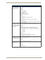
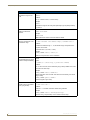
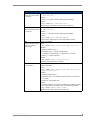
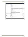
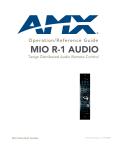
Operation/Reference Guide
Mio Modero® R-3
Remote Control Device
M i o R e m o t e C on t r ol s
Last Updated: 1/29/2008
AMX Limited Warranty and Disclaimer
AMX warrants its products to be free of defects in material and workmanship under normal use for three (3) years from
the date of purchase from AMX, with the following exceptions:
•
Electroluminescent and LCD Control Panels are warranted for three (3) years, except for the display and touch
overlay components that are warranted for a period of one (1) year.
•
Disk drive mechanisms, pan/tilt heads, power supplies, and MX Series products are warranted for a period of one
(1) year.
•
AMX Lighting products are guaranteed to switch on and off any load that is properly connected to our lighting
products, as long as the AMX Lighting products are under warranty. AMX does guarantee the control of dimmable
loads that are properly connected to our lighting products. The dimming performance or quality cannot be guaranteed due to the random combinations of dimmers, lamps and ballasts or transformers.
•
Unless otherwise specified, OEM and custom products are warranted for a period of one (1) year.
•
AMX Software is warranted for a period of ninety (90) days.
•
Batteries and incandescent lamps are not covered under the warranty.
This warranty extends only to products purchased directly from AMX or an Authorized AMX Dealer.
All products returned to AMX require a Return Material Authorization (RMA) number. The RMA number is obtained
from the AMX RMA Department. The RMA number must be clearly marked on the outside of each box. The RMA is
valid for a 30-day period. After the 30-day period the RMA will be cancelled. Any shipments received not consistent
with the RMA, or after the RMA is cancelled, will be refused. AMX is not responsible for products returned without a
valid RMA number.
AMX is not liable for any damages caused by its products or for the failure of its products to perform. This includes any
lost profits, lost savings, incidental damages, or consequential damages. AMX is not liable for any claim made by a
third party or by an AMX Dealer for a third party.
This limitation of liability applies whether damages are sought, or a claim is made, under this warranty or as a tort claim
(including negligence and strict product liability), a contract claim, or any other claim. This limitation of liability cannot
be waived or amended by any person. This limitation of liability will be effective even if AMX or an authorized representative of AMX has been advised of the possibility of any such damages. This limitation of liability, however, will not
apply to claims for personal injury.
Some states do not allow a limitation of how long an implied warranty last. Some states do not allow the limitation or
exclusion of incidental or consequential damages for consumer products. In such states, the limitation or exclusion of
the Limited Warranty may not apply. This Limited Warranty gives the owner specific legal rights. The owner may also
have other rights that vary from state to state. The owner is advised to consult applicable state laws for full determination of rights.
EXCEPT AS EXPRESSLY SET FORTH IN THIS WARRANTY, AMX MAKES NO OTHER WARRANTIES,
EXPRESSED OR IMPLIED, INCLUDING ANY IMPLIED WARRANTIES OF MERCHANTABILITY OR FITNESS FOR
A PARTICULAR PURPOSE. AMX EXPRESSLY DISCLAIMS ALL WARRANTIES NOT STATED IN THIS LIMITED
WARRANTY. ANY IMPLIED WARRANTIES THAT MAY BE IMPOSED BY LAW ARE LIMITED TO THE TERMS OF
THIS LIMITED WARRANTY.
Table of Contents
Table of Contents
Overview ............................................................................................................1
The Mio Modero® R-3 .............................................................................................. 1
Touch And Tilt Sensor ..................................................................................................... 2
Specifications .................................................................................................................. 2
FCC Compliance ....................................................................................................... 3
Mio Modero R-3 Setup .......................................................................................5
Inserting or Replacing the Lithium-ion Battery for the Mio
R-3 ......................................................................................................................... 5
Battery Low Indicator ............................................................................................... 5
Installing Custom Buttons ......................................................................................... 6
Setup Mode ........................................................................................................7
Transmit Mode.......................................................................................................... 7
Timeout Adjustment ................................................................................................. 7
Download Mode ....................................................................................................... 8
Debug Mode............................................................................................................. 8
Firmware Version...................................................................................................... 8
Device ID .................................................................................................................. 8
LED Awake Brightness.............................................................................................. 8
LED Sleep Mode Brightness ..................................................................................... 9
ZigBee ID PAN, Channel, and System Connection.................................................... 9
Site Survey................................................................................................................ 9
Programming The Mio R-3 ................................................................................11
Using the Programming Jack on The Mio R-3 ......................................................... 11
Updating Mio R-3 Firmware.................................................................................... 12
Channel Codes........................................................................................................ 13
Serial Commands .................................................................................................... 15
Send_Commands .................................................................................................... 21
Mio Remote Charging Base ..............................................................................27
Specifications ......................................................................................................... 27
Charging The Mio Remote with Charging Base ...................................................... 28
Mio Modero R-3 Remote
i
Table of Contents
ii
Mio Modero R-3 Remote
Overview
Overview
The Mio Modero® R-3
The Mio Modero® R-3 remote provides custom control features, contained in an elegant handheld
rechargeable device. The Mio R-3 communicates with a NetLinx® master via a wireless Zigbee®
network. Selecting a source device sends a command to the master and runs predetermined events
associated with that source. Selecting a macro will run predefined events, which might not be associated
with sources listed, then return the device to its previous mode.
You need VisualArchitect and KeypadBuilder to properly program this device. The application and
documentation are available from www.amx.com.
Power
1
Transmission Mode
Current Menu
Battery Meter
Custom Macro
Buttons
Custom Mode
2
3
4
5
6
7
8
9
10
11
12
13
14
15
17
16
18
19
20
21
22
23
25
24
Options
1 - Power
14 - Select
2 - Record
15 - Move Right
3 - Pause
16 - Guide
4 - Stop
17 - Exit
5 - Rewind
18 - Move Down
6 - Play
19 - Volume Up
7 - Fast Forward
20 - Last Selected
8 - Skip Back
21 - Channel Down
9 - Skip Forward
22 - Mute
10 - Menu
23 - Volume Down
11- Info
24 - Channel Down
12 - Move Up
25 - Input
13 - Move Left
26 - Enter
26
Numeral Keypad
FIG. 1 The Mio R-3 Device
Mio Modero R-3 Remote
1
Overview
Touch And Tilt Sensor
The Mio R-3 wakes up upon touching either the chrome side rails or pressing a button. When the remote
times out while holding it, you can reawaken the device by tilting it. Errant jostling, such as a bumped
table, will not wake the device unless you are actually holding it.
Specifications
The Mio R-3 device specifications are as follows:
Mio R-3 (FG148-03) Specifications
Battery
Rechargeable Lithium-Ion
Transmission
Frequencies
• Zigbee RF wireless network
• IR 38 Khz
• IR 455 Khz
Transmission Range
• ZigBee: 100 feet (30.48m)
• IR 38 Khz: 100 feet (30.48m)
• IR 455 Khz: 50 feet (15.24m)
Top Components
• LED - blue backlit buttons indicate device is awake
• Display (OLED) - 128 x 32 pixels, active area is 29.42mm x 7.98mm
• Pushbuttons - the power button is red backlit; the rest are blue backlit buttons. 45
buttons; 9 custom buttons (3 macro and 6 device).
Rear Component
• Programming Port - 2.5 mm stereo female conductor jack
• Battery Door
• Rechargeable Battery Connection
Dimensions (HWD)
9.50" x 2.00" x .74" (241.3 mm x 50.8 mm x 18.80 mm)
Supported Languages:
• English
• Japanese
• Spanish
• French
• Korean
• German
• Simplified Chinese
• Other languages
supported by Glyphs
• Greek
• Portuguese
• Italian
• Russian
Weight
• .45 lbs (20 kg) without battery
• .55 lbs (25 kg) with battery
Certifications
• FCC ID: CWU-ZMO
• CE
• IEC-60950
• TELEC
Operating Environment: • Operating Temperature: 0° to 40° C (32° to 104° F)
• Storage Temperature: -20° to 70° C (-4° to 158° F)
• Relative Humidity: 5% to 85%
Included Items:
• Mio-RBP Rechargeable Lithium-ion Battery (FG147-10)
Other AMX Equipment
• DB-9 extension cable (FG10-727)
• Programming Cable - a 3 wire, 2.5 mm stereo jack (FG10-817)
• Custom engraving (FG147-01)
• Mio-RCC Kit (FG147-03K)
• Mio-RCC Charging Base (FG147-02)
• NXR-ZGW (FG5791-01)
• NXR-ZRP (FG5791-02)
2
Mio Modero R-3 Remote
Overview
FCC Compliance
This radio module was tested and certified as a stand-alone device according to FCC Rules CFR 47, Part
15, Subpart C. If this device is installed in a manner such that the radio module FCC ID. label is not
visible on the outside of the end product, a label must be placed on the end product with the following
statement:
"Contains FCC ID. CWU-NXR-MO"
This device complies with Part 15 of the FCC rules. Subject to the following two conditions:
1. This device must not cause harmful interference and
2. This device must accept all interference, including interference that interferes with the operation of
this device. "
The User manual for the end-device must contain the following statements in a prominent place in the
manual.
Modifications not expressly approved by the manufacturer will void the user’s authority to operate the
equipment.
This device has been evaluated and found to be compliant with the FCC Rules for RF
Exposure when the device is operated at a minimum separation distance of 2 cm.
from the user and nearby persons. Operation of this device at closer distances
should be avoided.
Mio Modero R-3 Remote
3
Overview
4
Mio Modero R-3 Remote
Mio Modero R-3 Setup
Mio Modero R-3 Setup
Inserting or Replacing the Lithium-ion Battery for the Mio
R-3
The Mio Modero R-3 comes with a rechargeable Lithium-Ion battery that needs to be installed before
use. To install your Lithium-Ion battery into the device:
1. Flip and turn the Mio R-3 device so that the buttons are facing away from you and the device is
upside down.
2. Holding the device in both hands, place your thumbs on the battery door and slide the battery door
free. The battery door should slide toward the bottom end of the device.
3. Connect the terminal end of the Lithium-Ion battery to the port as shown in FIG. 2. It may be
necessary to use a thin, blunt, non-conductive object to seat the battery connector fully within its
port.
Lithium-Ion Battery
Rechargeable
Battery
Port Connection
Correct path for battery
wires and connector
Rear view Battery Compartment
FIG. 2 Rechargeable Battery Port on The Mio Remote
Make sure to inset the battery wires in the case as shown in FIG. 2, or the wires may
be damaged when replacing the battery door.
4. Place the battery door back on the device, and slide the door upwards to lock it in place.
Battery Low Indicator
When the battery charge level is too low to sustain continuous operation, the LCD flashes "Battery
Low". If not recharged, the LCD will flash again, and then the device shuts down to prevent a total
discharge of the battery. To recharge the battery, insert the Mio R-3 into the Mio Remote Charging Base
(see the Mio Remote Charging Base section on page 27).
Mio Modero R-3 Remote
5
Mio Modero R-3 Setup
Installing Custom Buttons
1. Flip and turn the Mio R-3 device so that the buttons are facing away from you and the device is
upside down.
2. Holding the Mio R-3 in both hands, place your thumbs on the battery door and push up to slide the
battery door free. The battery door will slide in the direction of the bottom end of the device.
3. Unscrew the 6 screw points indicated in FIG. 3.
6 Screw Points
Programming Jack
FIG. 3 Internal Mio R-3 Components
4. Turn the unit over so that the buttons are facing you.
5. Lift the top assembly away from the PCB.
6. If necessary, push out the standard buttons from the front of the top assembly.
7. Drop on your custom button pad and verify the alignment with the guide posts on the PCB.
8. Place the top assembly back down on the PCB and return the unit over, exposing the 6 screw points.
9. Tighten the 6 screw points.
10. Replace the battery door, and slide the door upwards to lock it in place.
6
Mio Modero R-3 Remote
Setup Mode
Setup Mode
The Setup mode allows you to set the following device features on the Mio R-3:
Transmit Mode
Timeout Adjustment
Download Mode
Debug Mode
Firmware Version
Device ID
LED Awake Brightness
LED Sleep Brightness
ZigBee ID PAN, Channel, and System Connection
Site Survey
To enter Setup mode:
1. Press and hold the STOP button and the INPUT button. The two buttons must be pressed within 0.1
seconds of each other and held down for 2 seconds. The device indicates you are now in Setup
mode. The available modes are listed below.
2. Press the EXIT key when you are finished. The Mio R-3 will automatically exit Setup mode after
30 seconds unless the device is in Download mode.
Your settings will not be lost in the event of battery removal or failure.
Transmit Mode
Press button 1 to select from one of the different available transmission modes. The Transmit mode
changes each time 1 is pressed. The predetermined modes are:
IR 38 Khz
IR 455 Khz
ZigBee Mode
IR 38 + ZigBee
IR 455 + ZigBee
The display indicates the selected mode. 30 seconds after selecting the mode, the menu returns to Setup
mode.
Timeout Adjustment
Press button 2 on the remote to change the sleep timeout from the default. Each time 2 is pressed, the
sleep timeout raises incrementally. The predetermined sleep timeouts are 3,6,9, and 12 seconds.
The display indicates the selected sleep timeout. 30 seconds after selecting the mode, the menu returns to
Setup mode.
Mio Modero R-3 Remote
7
Setup Mode
Download Mode
In order to download new firmware or a new configuration or font file to the Mio R-3 remote using the
remote's program port (see Using the Programming Jack on The Mio R-3 section on page 11 for details),
the remote must first be placed into Download mode. Press 3 on the remote to toggle the Download
mode OFF and ON. The Download mode must be ON before you can download a file to the Mio R-3
device. While the Download mode is ON, the device will not go to sleep. Once the download is
complete, this setting must be returned to Download Off. A firmware download will cause the remote to
reset and this will automatically reset the remote to Download Off.
To leave Download mode, press the EXIT button.
Debug Mode
Pressing button 4 on the remote toggles Debug mode between ON and OFF.
The remote has a useful feature known as Debug mode. When the remote is in Debug mode, pressing
any of the remote's buttons will cause the remote to display the corresponding channel code (used for
programming the control system) on the remote. The channel code will be shown on the remote as long
as the button is pressed. The remote indicates that it is in Debug mode by displaying the word DEBUG
between button presses.
Pressing the 4 button toggles to the new mode. 30 seconds after selecting the mode, the menu returns to
Setup mode.
Firmware Version
Pressing button 5 on the remote displays the remote and ZigBee firmware versions currently loaded on
the remote. To view the available firmware versions, press the Move Up arrow on the scroll wheel (refer
to the The Mio Modero® R-3 section on page 1 for more information) to scroll up. and pressing the
Move Down arrow will scroll down. When finished, press Exit to save the changed firmware
information and leave Setup mode.
Device ID
Pressing button 6 displays the device’s Device ID number. The default Device ID number is 10001, with
the first "1" highlighted, signaling to the user that it can be changed.
To change the Device ID number, press the Move Up arrow on the scroll wheel to scroll up. and pressing
the Move Down arrow will scroll down. To move the cursor to the next number, use the Move Left or
Move Right arrows on the scroll wheel to change positions.
After all numbers have been configured as desired, pressing the center button on the scroll wheel will
store the entered Device ID into memory. After the Device ID is stored into memory, the display will
return to Setup mode.
LED Awake Brightness
The red LEDs that backlight the Power button when the remote is awake are also used to indicate
charging status. These LEDs will slowly blink on and off if the remote is place in the charging cradle and
the Lithium-Ion battery pack is being charged. The LEDs will remain on when charging is complete.
Pressing button 7 will change the brightness of the Power LED from Low, to Med and then High.
Pressing the button again toggles to the new mode. 30 seconds after selecting the mode, the menu returns
to Setup mode.
8
Mio Modero R-3 Remote
Setup Mode
LED Sleep Mode Brightness
The red LEDs that backlight the Power button when the remote is awake are also used to indicate
charging status. These LEDs will slowly blink on and off if the remote is place in the charging cradle and
the Lithium-Ion battery pack is being charged. The LEDs will remain on when charging is complete.
This setting controls the brightness of these LEDs when the remote is sleeping. When the remote is in
Setup mode, pressing the 8 button will toggle between four brightness settings - Sleep: Low, Med, and
Off. Pressing the button again toggles to the new mode. 30 seconds after selecting the mode, the menu
returns to Setup mode.
ZigBee ID PAN, Channel, and System Connection
Pressing the 9 button will display the current ZigBee Personal Area Network (PAN) ID and channel for
the device. (For more information on ZigBee Personal Area Networks, refer to the NXR-ZGW and NXRZRP User Manual.) In order to display the NetLinx Master IP and ZigBee gateway EUI addresses, press
the Move Up arrow on the scroll wheel to scroll up. and pressing the Move Down arrow will scroll
down. When finished, press Exit to save the PAN ID and channel information and leave Setup mode. The
display will return to Setup mode 30 seconds after releasing the 9 button.
Site Survey
Pressing the 0 button makes the Mio R-3 scan all frequencies and store all active PAN IDs and Channels
in memory. The display will show the first accessible PAN ID and Channel.
To display other PAN IDs and Channels found in the area, press the Move Up or Move Down arrows on
the scroll wheel until the remote displays the desired PAN ID and Channel.
To connect to a particular PAN ID, pressing the center button on the scroll wheel will initiate the remote
to connect to a network.
If no networks were found, the display will read SCAN FAIL before returning to Setup mode. To exit
the Site Survey, press the Exit button.
Mio Modero R-3 Remote
9
Setup Mode
10
Mio Modero R-3 Remote
Programming The Mio R-3
Programming The Mio R-3
Most functionality of the Mio R-3 is handled using the KeypadBuilder application. Go to www.amx.com
for the KeypadBuilder Instruction Manual.
The Mio R-3 recognizes a select number of Serial Commands. For a full list and descriptions, consult the
Serial Commands section on page 15.
Using the Programming Jack on The Mio R-3
The programming jack is used for communication between the device and KeypadBuilder. The
programming jack uses a three-wire, 2.5mm stereo jack, and you may order the programming cable
(FG10-817) from AMX if you do not currently possess one. The Mio R-3 communicates at a 115200
baud rate.
To download KeypadBuilder Configuration Files:
1. Set the Mio R-3 Download mode to ON. See the Setup Mode section on page 7 for details.
2. Flip and turn the device so that the buttons are facing away from you and the device is upside down.
3. Holding the device in both hands, place your thumbs on the battery door and slide the battery door
free. The battery door will slide in the direction of the bottom end of the device.
4. Connect the 2.5mm stereo plug (male) end of the programming cable (FG10-817) into the
programming jack on the bottom side of the remote device.
5. If necessary, connect the DB-9 end of the programming cable to the female DB-9 connector on the
DB-9 extension cable (FG10-727).
6. Connect the female DB-9 terminal end of the extension cable to the port on the back of your
computer.
7. Configure the communication parameters in KeypadBuilder.
Programming
jack
Mio R-3
DB-9 connector
Stereo plug male
Keypad device
to PC
programming
cable
Cable FG10-817 to cable FG10-727
FIG. 4 Connecting The Keypad Device to Your PC
Mio Modero R-3 Remote
11
Programming The Mio R-3
Updating Mio R-3 Firmware
Updating firmware in the Mio R-3 is also done through the programming jack. To update the main
firmware for the Mio R-3:
1. Connect the Mio R-3 to your computer via the programming jack (FIG. 4).
2. Put the device into Download mode, as shown on page 8.
3. Open NetLinx Studio.
4. Set the Master Communication Settings to Axcess Master and set the baud rate to 115200.
5. Go to Tools > Firmware Transfers > Send to Axcess Device... This opens the Send to Axcess
Dialog Window(FIG. 5)..
FIG. 5 Send to Axcess Dialog Window
6. Browse to the location of the firmware file.
7. Select the file within the Files frame.
You must download two .tsk files for the Mio R-3: one main firmware file, and one for
the ZigBee module.
8. Click Query for Devices.
9. The Query For Devices field will display a complete list of all devices currently connnected to
NetLinx Studio capable of accepting the firmware file selected. Select the Mio R-3.
10. Click Send.
11. After device firmware download, check one more time to verify the firmware version change.
12. Click Close.
13. Upon confirmation of a successful send, you can exit NetLinx Studio and disconnect the
programming jack.
If you are using the Mio R-3 in conjunction with other ZigBee-enabled devices, such
as the Mio R-4 and the NXA-ZGW wireless gateway, you should update the firmware
to all of the ZigBee devices at the same time.
12
Mio Modero R-3 Remote
Programming The Mio R-3
Channel Codes
The following table gives the channel codes associated with each button on the Mio R-3. Thirty-six of
the buttons change channel codes based on what button was last pressed. Nine of the buttons always emit
the same channel code regardless of what button was last pressed.
The Mio R3 also works in "single device mode," configurable by setting the mode to dynamic and the
number of devices to 1 (see the Send_Commands section on page 21). That is, it always emits the same
channel for the buttons. Code on the NetLinx master can interpret and re-map the channel depending on
what device mode the Mio R3 is in, from selecting Device 1 - Device 6, or a combination for extra
devices.
Channel Codes
Button
Dev 1
Dev 2
Dev 3
Dev 4
Dev 5
Dev 6
PLAY q
1
41
81
121
161
201
STOP w
2
42
82
122
162
202
PAUSE e
3
43
83
123
163
203
FFW t
4
44
84
124
164
204
REW i
5
45
85
125
165
205
S.FFD y
6
46
86
126
166
206
S.REV u
7
47
87
127
167
207
REC p
8
48
88
128
168
208
Power Symbol
9
49
89
129
169
209
0
10
50
90
130
170
210
1
11
51
91
131
171
211
2
12
52
92
132
172
212
3
13
53
93
133
173
213
4
14
54
94
134
174
214
5
15
55
95
135
175
215
6
16
56
96
136
176
216
7
17
57
97
137
177
217
8
18
58
98
138
178
218
9
19
59
99
139
179
219
ENTER
21
61
101
141
181
221
CH+
22
62
102
142
182
222
CH-
23
63
103
143
183
223
VOL +
24
64
104
144
184
224
VOL -
25
65
105
145
185
225
MUTE
26
66
106
146
186
226
INPUT
29
69
109
149
189
229
MENU
31
71
111
151
191
231
Mio Modero R-3 Remote
13
Programming The Mio R-3
Channel Codes (Cont.)
14
Button
Dev 1
Dev 2
Dev 3
Dev 4
Dev 5
Dev 6
Up
32
72
112
152
192
232
Down
33
73
113
153
193
233
Left
34
74
114
154
194
234
Right
35
75
115
155
195
235
SELECT
36
76
116
156
196
236
EXIT
37
77
117
157
197
237
GUIDE
38
78
118
158
198
238
INFO
39
79
119
159
199
239
LAST
40
80
120
160
200
240
TV (Device 1)
241
241
241
241
241
241
SAT (Device 2)
242
242
242
242
242
242
DVD (Device
3)
243
243
243
243
243
243
CD (Device 4)
244
244
244
244
244
244
AUX (Device
5)
245
245
245
245
245
245
LGHT (Device
6)
246
246
246
246
246
246
A (Macro 1)
250
250
250
250
250
250
B (Macro 2)
251
251
251
251
251
251
C (Macro 3)
252
252
252
252
252
252
Mio Modero R-3 Remote
Programming The Mio R-3
Serial Commands
The Mio R-3 remote supports a few commands that can be uploaded to the device using a terminal
program such as HyperTerminal. These commands are not needed for normal usage or programming of
the remote.
Serial Commands
@BRT
Set Brightness level
This command can be used to customize the brightness of the red LEDs that
backlight the power button if the predefined brightnesses in Setup Mode are
not fine enough.
Syntax:
"'BRIT-<awake brightness level>,<sleep brightness
level>'"
Variables:
brightness level # = a value from 0 - 32.
"'@BRT-#'"
(Set LED Awake brightness level)
"'@BRT-#,#'"
(Set LED Awake brightness level, sleep brightness level)
Example:
(1) "'@BRT-16'"
Sets the awake brightness level to 50%.
^CFG #
Enable or Disable Debug
Mode
Syntax:
^CFG- <command value>
Variables:
• # = (1 = Debug Mode ON, 0 = Debug Mode OFF).
Example:
^CFG-1
Turn Debug Mode ON
Mio Modero R-3 Remote
15
Programming The Mio R-3
Serial Commands (Cont.)
^FML
^FML S
Sets a line of the display to a menu line
Syntax:
"'^FML-<variable text address range>,S'"
Variables:
• variable text address range = 1; the address range corresponds to the
dynamic line number-only one line is supported on this device.
Example:
SEND_COMMAND Panel,"'^FML-1,S'"
Sets dynamic line to a menu line
^FML D
Sets a line of the display to a dynamic line with no level
Syntax:
"'^FML-<variable text address range>,D'"
Variables:
• variable text address range = 1; the address range corresponds to the
dynamic line number-only one line is supported on this device.
Example:
SEND_COMMAND Panel,"'^FML-2,D'"
Set Line 2 to a Dynamic Line with no Level
^FML D L Sets a line of the display to a dynamic line with a level
Syntax:
"'^FML-<variable text address range>,D,L'"
Variables:
• variable text address range = 1; the address range corresponds to the
dynamic line number-only one line is supported on this device.
Example:
SEND_COMMAND Panel,"'^FML-1,D,L'"
Set line 1 to a Dynamic line with level
^FML D L # Sets a line of the display to a dynamic line with a level, and sets
the level style
Syntax:
"'^FML-<variable text address range>,D,L,<Level Style>'"
Variables:
• variable text address range = 1; the address range corresponds to the
dynamic line number-only one line is supported on this device.
Example:
SEND_COMMAND Panel,"'^FML-1,D,L,0'"
Set line 1 to a Dynamic line with level and set style to 'Level Style 0'
Note: You can enter one of two values for level style: 0 and 1. Style 0 is the
default value which displays a rectangle bargraph. Style 1 displays a linear
bargraph.
^GLY
Set a glyph to display
Syntax:
'^GLY-<variable text address range>,<glyph number>'"
Example:
SEND_COMMAND Panel,"'^GLY-1,10'"
Set a glyph with index 10 to the Mio-R3 display.
Note: This only works if a glyph file has been loaded from KeypadBuilder.
16
Mio Modero R-3 Remote
Programming The Mio R-3
Serial Commands (Cont.)
IRMODE #
Sets the IR transmission
frequency to either 38 or
455KHz
Syntax:
IRMODE #
Variables:
• <mode> =
38 - IR only, 38KHz
455 - IR only, 455KHz
ZIG - ZigBee only
ZIG38 - ZigBee + IR 38KHz
ZIG455 - ZigBee + IR 455KHz
Example:
IRMODE 455
Sets the IR transmission frequency to 455 KHz.
IRMODE ZIG
Sets the IR to disabled and communications to only use ZigBee.
IRMODE ZIG38
Sets the IR transmission frequency to 38KHz and configures for simultaneous
transmission on ZigBee.
^JST
Set text alignment using a
numeric keypad layout for
those buttons with a defined
address range
Syntax:
"'^JST-<variable text address range>,<new text
alignment>'"
Variable:
• variable text address range = 1; the address range corresponds to the
dynamic line number-only one line is supported on this device.
• new text alignment = Value of 1 - 9 corresponds to the following locations:
1, 4 or 7 = Left
2, 5 or 8 = Center
3, 6 or 9 = Right
Example:
SEND_COMMAND Panel,"'^JST-1,1'"
Sets the text alignment to the left side of the LCD button
Note: There is no vertical alignment.
NUMD
Sets the number of devices to
be controlled by the remote
Syntax:
NUMD <numberOfDevices>
Example:
NUMD 1
Sets the remote to control only one device.
REBOOT
Reboots the remote
Syntax:
REBOOT
Example:
REBOOT
Reboots the remote
Mio Modero R-3 Remote
17
Programming The Mio R-3
Serial Commands (Cont.)
REVD #
Reverse the image on the
LCD
Syntax:
REVD #
Variables:
• # = (1 = Reverse video, 0 = Normal Video)
Example:
REVD 1
Reverses the image on the LCD; pixels previously lit go off; pixels previously
off, come on.
SETD
Sets the ICSP Device
Number
Syntax:
SETD <deviceNum>
Example:
SETD 10020
Note: ICSP Device number cannot be set above 32000.
^SHO
Syntax:
Show or hide text with a set
variable text range
Variables:
"'^SHO-<variable text address range>,<command value>'"
• variable text address range = 1 - 6; the address range corresponds to the
dynamic line number.
• command value = (0= hide, 1= show).
Example:
SEND_COMMAND Panel,"'^SHO-1,0'"
Hides text on dynamic line 1 of the LCD button.
SLEEP-#
Set the Sleep timer or put the
remote to sleep immediately.
This command can be used if a sleep time other than 3, 6, 9, or 12 seconds is
desired.
Syntax:
"'SLEEP-#'" (timed sleep; a persistent command)
Variables:
• # = 0 - 60 in seconds; time to wait before going to sleep. Default is 30. 0 sets
the device to never sleep.
Example:
SEND_COMMAND Panel,"'SLEEP-45'"
Sets the sleep timer to 45 seconds. After 45 seconds of inactivity, the remote
will go to sleep.
SEND_COMMAND panel,"'SLEEP'"
Force the keypad to go to sleep.
@SSL
Sends a string to the master
upon going to sleep
Syntax:
"'@SSL-<new text>'"
Variables:
• new text = 1 - 20 ASCII characters. Default string is SLEEP.
Example:
SEND_COMMAND Panel,"'@SSL-KeyPad Sleep'"
Sends the string " KeyPad Sleep'" to the master at time of sleep.
18
Mio Modero R-3 Remote
Programming The Mio R-3
Serial Commands (Cont.)
@SST
Sends a string to the master
upon startup
Syntax:
"'@SST-<new text>'"
Variables:
• new text = 1 - 20 ASCII characters. Default string is STARTUP.
Example:
SEND_COMMANDPanel,"'@SST-Panel Start'"
Sends the string " Panel Start " to the master at time of start up.
@SWK
Sends a string to the master
upon wake up
Syntax:
"'@SWK-<new text>'"
Variables:
• new text = 1 - 20 ASCII characters. Default string is WAKEUP.
Example:
SEND_COMMAND Panel,"'@SWK-Wake KeyPad"
Sends the string " Wake KeyPad " to the master at time of wake up.
^TXT
Sets non-unicode text.
Assign a text string to those
buttons with a defined
address range
Syntax:
SEND_COMMAND <DEV>,"'^TXT-<vt addr range>,<new text>'"
Variables:
• variable text address range = 1.
• button states range = 1 - 256 for multi-state buttons
(0 = All states, for General buttons 1 = Off state and 2 = On state).
• new text = 1 - 50 ASCII characters.
Example:
SEND_COMMAND Keypad,"'^TXT-1,Test Only'"
Sets the On and Off state text for the display.
^UNI
Set Unicode text
For the ^UNI command (%UN and ^BMF command), the Unicode text is sent
as ASCII-HEX nibbles.
Syntax:
SEND_COMMAND <DEV>,"'^UNI-<vt addr range>,<button states
range>,<unicode text>'"
Variables:
• variable text address range = 1.
• button states range = (0 = All states, for General buttons 1 = Off state and
2 = On state).
• unicode text = Unicode HEX value.
Example:
To send the variable text 'A' in Unicode to all states of the variable text display,
(for which the character code is 0041 Hex), send the following command:
SEND_COMMAND Keypad,"'^UNI-1,0,0041'"
Note: Unicode is always represented in a HEX value.
Mio Modero R-3 Remote
19
Programming The Mio R-3
Serial Commands (Cont.)
ZAP!
Erase Configuration
Information in Flash Memory
Syntax:
ZAP! t
Variables:
• t = MENU or FONT or blank
Example:
ZAP!
Clears all configuration information and erases the font. The text displayed on
the LCD for the six devices returns to default and all parameters that can be set
in Setup Mode are reset to their default value.
ZAP! MENU
Sets the text displayed on the LCD for the six devices to the default values.
ZAP! FONT
Erases the font from the flash.
NOTE: These commands are intended for serial use only. These commands
cannot be issued when the device’s Setup Page is open.
ZIGC
Sets the ZigBee Channel
Syntax:
ZIGC <channel> (Decimal)
Example:
ZIGC 26
ZIGP
Sets the ZigBee PAN ID
Syntax:
ZIGP <panId> (Decimal)
Example:
ZIGP 123A
20
Mio Modero R-3 Remote
Programming The Mio R-3
Send_Commands
When used with ZigBee communications and a NetLinx master, the Mio R-3 supports a small set of
Send_Commands. The table below captures all Send_Commands supported by the Mio R3
Send_Commands
@BRT
Set Brightness level
This command can be used to customize the brightness of the red LEDs that
backlight the power button if the predefined brightnesses in Setup Mode are
not fine enough.
Syntax:
@BRT- <awake brightness level>, <sleep brightness level>
Variables:
• # = a value from 0 - 32.
@BRT- #
(Set LED Awake brightness level)
@BRT- #, #
(Set LED Awake brightness level, sleep brightness level)
Example:
@BRT-16
Sets the awake brightness level to 50%.
@BRT-32,5
Sets the awake brightness level to 100% and sleep brightness level to
approximately 15%
^CFG
Enable or Disable Debug
Mode
Syntax:
^CFG- <command value>
Variables:
• # = (1 = Debug Mode ON, 0 = Debug Mode OFF).
Example:
^CFG-1
Turn Debug Mode ON
^FML
Sets a line of the display to a
menu line
Syntax:
"'^FML-<variable text address range>,S'"
Variables:
• variable text address range = 1; the address range corresponds to the
dynamic line number.
Example:
SEND_COMMAND Panel,"'^FML-1,S'"
Sets dynamic line 1 to a menu line
Mio Modero R-3 Remote
21
Programming The Mio R-3
Send_Commands (Cont.)
^FML
^FML S
Sets a line of the display to a menu line
Syntax:
"'^FML-<variable text address range>,S'"
Variables:
• variable text address range = 1; the address range corresponds to the
dynamic line number-only one line is supported on this device.
Example:
SEND_COMMAND Panel,"'^FML-1,S'"
Sets dynamic line to a menu line
^FML D
Sets a line of the display to a dynamic line with no level
Syntax:
"'^FML-<variable text address range>,D'"
Variables:
• variable text address range = 1; the address range corresponds to the
dynamic line number-only one line is supported on this device.
Example:
SEND_COMMAND Panel,"'^FML-1,D'"
Set Line 1 to a Dynamic Line with no Level
^FML D L Sets a line of the display to a dynamic line with a level
Syntax:
"'^FML-<variable text address range>,D,L'"
Variables:
• variable text address range = 1; the address range corresponds to the
dynamic line number-only one line is supported on this device.
Example:
SEND_COMMAND Panel,"'^FML-1,D,L'"
Set line 1 to a Dynamic line with level
^FML D L # Sets a line of the display to a dynamic line with a level, and sets
the level style
Syntax:
"'^FML-<variable text address range>,D,L,<Level Style>'"
Variables:
• variable text address range = 1; the address range corresponds to the
dynamic line number-only one line is supported on this device.
Example:
SEND_COMMAND Panel,"'^FML-1,D,L,0'"
Set line 1 to a Dynamic line with level and set style to 'Level Style 0'
Note: You can enter one of two values for level style: 0 and 1. Style 0 is the
default value which displays a rectangle bargraph. Style 1 displays a linear
bargraph.
^GLY
Set a glyph to display
Syntax:
'^GLY-<variable text address range>, <glyph number>'"
Example:
SEND_COMMAND Panel,"'^GLY-1,10'"
Set a glyph with index 10 to the Mio-R3 display.
Note: This only works if a glyph file has been loaded from KeypadBuilder.
22
Mio Modero R-3 Remote
Programming The Mio R-3
Send_Commands (Cont.)
^JST
Set text alignment using a
numeric keypad layout for
those buttons with a defined
address range
Syntax:
'^JST-<variable text address range>,<new text
alignment>'"
Variable:
• variable text address range = 1; the address range corresponds to the
dynamic line number.
• new text alignment = Value of 1 - 9 corresponds to the following locations:
1, 4 or 7 = Left
2, 5 or 8 = Center
3, 6 or 9 = Right
Example:
SEND_COMMAND Panel,"'^JST-1,1'"
Sets the text alignment to the left side on dynamic line 1 of the LCD button
Note: There is no vertical alignment.
NUMD
Sets the number of devices to
be controlled by the remote
Syntax:
NUMD <numberOfDevices>
Example:
NUMD 1
Sets the remote to control only one device.
REBOOT
Reboots the unit
Syntax:
"'REBOOT'"
Example:
SEND_COMMAND Panel,"'REBOOT'"
Forces the device to reboot
SETD
Sets the ICSP Device
Number
Syntax:
SETD <deviceNum>
Example:
SETD 10020
^SHO
Show or hide text with a set
variable text range
Syntax:
"'^SHO-<variable text address range>,<command value>'"
Variables:
• variable text address range = 1; the address range corresponds to the
dynamic line number.
• command value = (0= hide, 1= show).
Example:
SEND_COMMAND Panel,"'^SHO-1,0'"
Hides text on dynamic line 1 of the LCD button.
Mio Modero R-3 Remote
23
Programming The Mio R-3
Send_Commands (Cont.)
SLEEP
Set the Sleep timer or put the
remote to sleep immediately.
This command can be used if a sleep time other than 3, 6, 9, or 12 seconds is
desired.
Syntax:
SLEEP
Forces keypad to turn backlight off.
SLEEP-#
Sets sleep time.
Variables:
• # = 0 - 60 in seconds; time to wait before going to sleep.
Example:
SLEEP-45
Sets the sleep timer to 45 seconds. After 45 seconds of inactivity, the remote
will go to sleep.
SEND_COMMAND panel,"'SLEEP'"
Force the keypad to go to sleep.
@SSL
Sends a string to the master
upon going to sleep
Syntax:
"'@SSL-<new text>'"
Variables:
• new text = 1 - 20 ASCII characters. Default string is SLEEP.
Example:
SEND_COMMAND Panel,"'@SSL-KeyPad Sleep'"
Sends the string " KeyPad Sleep'" to the master at time of sleep.
@SST
Sends a string to the master
upon start up
Syntax:
"'@SST-<new text>'"
Variables:
• new text = 1 - 20 ASCII characters. Default string is STARTUP.
Example:
SEND_COMMAND Panel,"'@SST-Panel Start'"
Sends the string " Panel Start " to the master at time of start up.
@SWK
Sends a string to the master
upon wakeup
Syntax:
"'@SWK-<new text>'"
Variables:
• new text = 1 - 20 ASCII characters. Default string is WAKEUP.
Example:
SEND_COMMAND Panel,"'@SWK-Wake KeyPad"
Sends the string " Wake KeyPad " to the master at time of wake up.
24
Mio Modero R-3 Remote
Programming The Mio R-3
Send_Commands (Cont.)
^TXT
Sets non-unicode text.
Assign a text string to those
buttons with a defined
address range
Syntax:
SEND_COMMAND <DEV>,"'^TXT-<vt addr range>,<button states
range>,<new text>'"
Variables:
• variable text address range = 1.
• button states range = 1 - 256 for multi-state buttons
(0 = All states, for General buttons 1 = Off state and 2 = On state).
• new text = 1 - 50 ASCII characters.
Example:
SEND_COMMAND Keypad,"'^TXT-1,1&2,Test Only'"
Sets the On and Off state text for the display.
Note: You must send an ^FML command before sending variable text to an
R3 remote.
^UNI
Set Unicode text
For the ^UNI command, the Unicode text is sent as ASCII-HEX nibbles.
Syntax:
SEND_COMMAND <DEV>,"'^UNI-<vt addr>,<unicode text>'"
Variables:
• variable text address range = 1.
• unicode text = Unicode HEX value.
Example:
SEND_COMMAND Keypad,"'^UNI-1,$00,$41'"
Sets the button's unicode character to 'A'.
Note: To send the variable text 'A' in Unicode to all states of the variable text
button 1, (for which the character code is 0041 Hex), send the following
command:
SEND_COMMAND Keypad,"'^UNI-1,$00,$41'"
Note: Unicode is always represented in a HEX value.
WAKE
Syntax:
Force the keypad to turn
backlight on
Example:
SEND_COMMAND <DEV>,"'WAKE'"
SEND_COMMAND Keypad,"'WAKE'"
Forces the keypad to turn backlight on.
ZIGC
Sets the ZigBee Channel
Syntax:
ZIGC <channel> (Decimal)
Example:
ZIGC 26
ZIGP
Sets the ZigBee PAN ID
Syntax:
ZIGP <panId> (Decimal)
Example:
ZIGP 123A
Mio Modero R-3 Remote
25
Programming The Mio R-3
26
Mio Modero R-3 Remote
Mio Remote Charging Base
Mio Remote Charging Base
The Mio remotes are complemented with a Mio-RCC charging base (FG147-02).
FIG. 6 Mio-RCC Charging Base
Specifications
Rubber feet
Angle barrel power connector
(Bottom View)
Charging contacts
(Top View)
FIG. 7 Mio Remote Charging Base (Top and Bottom view)
Mio Modero R-3 Remote
27
Mio Remote Charging Base
The specifications for the Mio remote charging base and kit are as follows:
Mio-RCC Remote Charging Kit (FG147-03K) with Base (FG147-02) Specifications
Dimensions (HWD)
Charging Base - 1.61 (4.09 cm) (height); 4.25 (10.80 cm) (diameter)
Lithium Ion Battery - 2.13” x 1.38” x .28” (5.41 cm x 3.45 cm x .71 cm)
Weight
• 1.15 lbs (.52 kg) - Remote Charging Cradle
• .15 lbs (.07 kg) - Power Supply
• .06 lbs (.027 kg) - Rechargeable Lithium Battery
Other AMX Equipment: • Mio R-1 (FG147)
• Mio R-2 RF 418 (FG147-418)
• Mio R-2 RF 433 (FG147-433)
• Mio R-3 (FG148-23K)
• Mio R-4 (FG148-04)
• NXR-ZGW (FG5791-01)
• NXR-ZRP (FG5791-02)
• Mio-RBP Rechargeable Lithium Ion Battery (FG147-10)
• AXR-RF 418 MHZ RF Receiver (FG782-418)
• AXR-RF 433 MHZ RF Receiver (FG782-433)
• Mio Modero IR Receiver (FG5797-01xx; xx indicates color)
Charging The Mio Remote with Charging Base
The Mio remotes receive power for charging from a charging base.
1. Connect the terminal end of the power supply to the bottom external power port on the Mio remote
charging base. See FIG. 7 for location.
2. Route the cable through the provided channel so that it comes out the side of the base.
3. Connect the power cord to an external power source.
4. Place the bottom of the Mio remote into the charging base so the contacts on the device are on top of
the charging contacts inside the charging base. The Power LED on the Mio remote blinks red to
indicate it is charging and illuminates solid red when it is done. Full charge cycle for a depleted
battery is approximately 3 hours.
28
Mio Modero R-3 Remote
Mio Remote Charging Base
Mio Modero R-3 Remote
29
1/08 ©2007 AMX. All rights reserved. AMX and the AMX logo are registered trademarks of AMX. AMX reserves the right to alter specifications without notice at any time.
It’s Your World - Take Control™
3000 RESEARCH DRIVE, RICHARDSON, TX 75082 USA • 800.222.0193 • 469.624.8000 • 469-624-7153 fax • 800.932.6993 technical support • www.amx.com