1
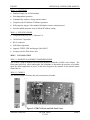
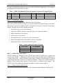
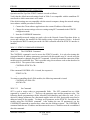
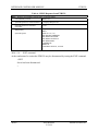
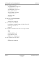
ETHCX1
INTERFACE CONTROLLER MODULE
MODEL 2020
ETHCX1
INTERFACE CONTROLLER MODULE
May 25, 2004
TABLE OF CONTENTS
2020.1
INTRODUCTION......................................................................................................... 2
2020.1.1
PURPOSE OF MODULE....................................................................................... 2
2020.1.2
MODULE OVERVIEW ......................................................................................... 2
2020.1.3
FEATURES ............................................................................................................ 3
2020.1.4
SPECIFICATIONS................................................................................................. 3
2020.2
INSTALLATION.......................................................................................................... 3
2020.2.1
MODULE PLACEMENT CONSIDERATIONS................................................... 3
2020.2.2
CABLES ................................................................................................................. 3
2020.2.3
JUMPER SETTINGS ............................................................................................. 4
2020.3
OPERATION AND SETUP......................................................................................... 4
2020.3.1
FRONT PANEL OPERATION.............................................................................. 4
2020.3.2
ETHERNET PORT OPERATION ......................................................................... 5
2020.3.3
ETHCX1 COMMAND SUMMARY ..................................................................... 5
2020.3.4
TYPICAL PROGRAMMING SEQUENCE: ......................................................... 9
APOGEE LABS, Inc.
AL4300 Series
5.25.04
2020-1
INTERFACE CONTROLLER MODULE
ETHCX1
MODEL 2020
ETHCX1
INTERFACE CONTROLLER MODULE
2020.1
INTRODUCTION
2020.1.1 PURPOSE OF MODULE
The Apogee Labs Model 2020 ETHCX1 module provides a remote control facility for a AL4300
Series chassis using an Ethernet 10/100 Base-T link. This facility supports all the remote
control commands listed in the individual manuals for the AL4300 modules installed in the
chassis. These commands are ASCII coded control and status interrogation commands, each of
which are individually Acknowledged. This is designated as the Network Native ASCII Transfer
or NNAT remote control mode.
2020.1.2 MODULE OVERVIEW
The control processor on the ETHCX1 receives incoming data from the Ethernet. Completed
commands received are then sent to the Front Panel Controller of the chassis via the internal
ALISDT bus. The Front Panel Controller in turn directs the data to the selected module. This
target module processes the command and provides a response back to the Front Panel
Controller, which forwards this to the ETHCX1. The ETHCX1 holds the response until
interrogated from the Ethernet.
The ETHCX1 setup consists of assigning the IP Address, Netmask, and Gateway on the
ETHCX1 by way of the Ethernet. Initial access to the module is made using the default values
indicated in Table 2. Once set, the values are retained in the non-volatile memory on the card
and are restored during each unit power-on sequence.
The following block diagram shown in Figure 1 presents a simplified overview of this module:
RJ-45
2
3
6
TX +
TX -
RX +
Ethernet
Magnetic
Matching
Network
ETHERNET
FRAMER
u Controller
Bus
Interface
ALISDT
1
RX -
Figure 1 - ETHCX1 Simplified Block Diagram
2020-2
AL4300Series
5.25.04
APOGEE LABS, Inc.
ETHCX1
INTERFACE CONTROLLER MODULE
2020.1.3 FEATURES
•
Standard single slot AL4300 module
•
Slot-independent operation
•
Automatically replaces existing remote control
•
Complies with 10/100 base-T Ethernet operation
•
Fully supports Apogee Labs standard full duplex remote control protocol
•
Switch-enabled automatic reset of default IP address setting
2020.1.4 SPECIFICATIONS
•
Compliant with IEEE 802.3 / Ethernet V.2
•
10/100 Base-T operation
•
RJ-45 connector
•
Full Duplex Operation
•
Supports TCP/IP, UDP and Apogee Labs NNAT
•
Occupies one AL4300 chassis slot
2020.2
INSTALLATION
2020.2.1 MODULE PLACEMENT CONSIDERATIONS
The ETHCX1 plug-in module may be placed anywhere within the AL4300 series chassis. The
front panel processor, which interrogates the backplane to determine the presence of modules
upon the initial application of power to the unit, recognizes this module as the default remote
control device.
2020.2.2 CABLES
The following figure illustrates the only connection to be made:
Figure 2 - ETHCX1 Front and Side Panel Views
APOGEE LABS, Inc.
AL4300 Series
5.25.04
2020-3
INTERFACE CONTROLLER MODULE
ETHCX1
Two pairs of unshielded twisted-pair wire are used in 10/100 BaseT applications. The connector
pin assignments are shown below in Table 1.
Table 1 - ETHCX1 Module RJ45 Network Interface Connector (J1) Signal Pin List
PIN
1
SIGNAL
TX+
DESCRIPTION
Transmit+
PIN
3
SIGNAL
RX+
DESCRIPTION
Receive +
2
TX-
Transmit -
6
RX-
Receive -
2020.2.3 JUMPER SETTINGS
There are no jumpers settings on the module that affect its operation.
One switch (see SW1 location on Figure 2) is used to initialize the module IP address, Net Mask
and Gateway to the factory defaults (Table 2). Should it be necessary to reset these to the factory
defaults, the following procedure should be followed:
1. Turn off the power to the AL4300 chassis.
2. Remove the ETHCX1 module, locate SW1 and set it to “Reset IP Address”.
3. Replace the module in its card slot.
4. Restore power to the chassis.
5. After approximately 5 seconds, turn off the chassis power.
6. Remove the module and reset the SW1 position to “Operating”.
7. Replace the module in the chassis and restore power.
Table 2 - Factory Default IP Address Settings
FUNCTION
IP Address
Netmask
Gateway
2020.3
IP ADDRESS
192.168.0.10
255.255.255.0
192.168.0.1
OPERATION AND SETUP
ETHCX1 Modules are designed so that the user never needs to install new or upgrade old
“system setup software”. Configuration of the AL4300 is done through either the front panel or
a remote control link. NNAT (Network Native ASCII Transfer) communications is used to
control and monitor the AL4300 on an Ethernet connection. When a new channel module is
installed, all the needed setup software for that module is contained on the module. The
ETHCX1 provides a transparent communication path to a remote control computer.
2020.3.1 FRONT PANEL OPERATION
The ETHCX1 module does not support nor require operation at the front panel of the AL4300.
2020-4
AL4300Series
5.25.04
APOGEE LABS, Inc.
ETHCX1
INTERFACE CONTROLLER MODULE
2020.3.2 ETHERNET PORT OPERATION
Operation and Set Up of the ETHCX1 module is made as follows:
Verify that the default network settings listed in Table 2 are compatible with the standalone PC
or network to which connection is to be made.
If the default settings are not compatible with the network computer, change the network settings
in accordance with the procedure as follows:
1. Connect the Client software application to the current IP address of the module.
2. Change the current settings to the new settings using SET commands in the ETHCX1
configuration mode.
3. Issue the CONFIRM IP instruction.
Once compatible network settings are made, refer to the Network Control Procedure below to
access and configure the installed AL4300 modules using a client program of choice. It should
be noted that the RS232 control port on the AL4300 is unusable when the ETHCX1 interface is
installed
2020.3.3 ETHCX1 COMMAND SUMMARY
2020.3.3.1
The CONTROL Command
The CONTROL command is used to access the ETHCX1 module. It is only after issuing this
command that the IP address parameters associated with this module may be viewed using the
READ command or changed using the SET command. It should be noted that connection to this
module must be established first. This is possible using client software such as that described in
section 2020.4. The syntax of this command is:
CONTROL=ETHCX1<CR>
>
If the command CONTROL<CR> is issued, the response is:
ETHCX1<CR>
>
To return to controlling the AL4300 modules, the following command is issued:
CONTROL=AL4300<CR>
AL4300<CR>
>
2020.3.3.2
Set Command
SET is used to assign values to programmable fields. The SET command has two fields
separated by a comma or an “=”,. These are: the parameter name and the parameter value. The
following details programming with the allowable field identifiers and values for each. If it is
desired to change parameters on a functional module in the AL4300, that module must first be
addressed using its slot number. To change an IP parameter on the ETHCX1, first address the
module using the CONTROL command. After loading the new IP parameter(s) use the
CONFIRM IP command to transfer these values into the working registers. The CONFIRM IP
command loads the new IP address and disconnects the server. Connection must be reestablished
after this command.
APOGEE LABS, Inc.
AL4300 Series
5.25.04
2020-5
INTERFACE CONTROLLER MODULE
ETHCX1
The valid range for the IP parameters is as follows:
Parameter Min
Max
IP Address
0.0.0.0 255.255.255.255
Net Mask
0.0.0.0 255.255.255.255
Gateway
0.0.0.0 255.255.255.255
Port
1501
65535
Table 3 - Set Command Format
SET – Sets parameter values
Command Entry Format
SET <Parameter Name>=<Parameter Value><CR>
System Response for Valid Command
<Parameter Name> <Parameter Value><CR>>
System Response for an Invalid Command
<CR>?
Sample Entry
SET IP Address=192.168.0.10<CR>
System Response-
IP Address 192.168.0.10<CR>>
Sample Invalid Entry
SET IP Address=192.168.010045<CR>
System Response
?
2020.3.3.3
CONFIRM IP Command
The CONFIRM IP command loads the values given to the module using the SET command for
IP Address, Netmask, Gateway and Port into the working registers. If this command is not
issued, the IP settings remain unchanged. The connection to the ETHCX1 is disconnected by
this command as well.
2020.3.3.4
RESET IP Command
The RESET IP command restores the IP settings to the default values. The values set are the
same as if the module was powered-up with the IP Address switch in the RESET position and
are as follows:
IP ADDRESS 192.168.0.10
NETMASK 255.255.255.0
GATEWAY 192.168.0.1
PORT 1501
2020.3.3.5
READ Command
READ is used to confirm values of programmed fields and to collect status associated with the
currently selected module. The READ command has one argument to designate the field.
2020-6
AL4300Series
5.25.04
APOGEE LABS, Inc.
ETHCX1
INTERFACE CONTROLLER MODULE
Table 4 - Read Command Format
READ – Displays the current parameter setting
Command Entry Format
READ <Parameter Name><CR>
System Response for Valid Command
READ <Parameter Name> <Parameter Value><CR>>
System Response for an Invalid Command
<CR>?
Sample Entry
READ IP Address<CR>
System Response
READ IP Address 192.168.0.10<CR>>
2020.3.3.5
SLOT Command
The SLOT command is required to permit accessing functional modules in the system. After
issuing this command the user gains access to the functions of the module contained in the
designated card slot.
Table 5 - The SLOT Command
SLOT – Accesses a selected module by its Slot number in the system
Command Entry Format
SLOT=<number><CR>
System Response for Valid Command
><System Prompt>
System Response for an Invalid Command
<CR>?
Sample Entry
SLOT=3
System Response
>
2020.3.3.6
[The user programs the module in slot 3]
Programming Example
A typical example to control a MUX9 module located as slot 3 in the chassis is as follows:
>slot=3
>set c1id=023
>set c2id=024
>
2020.3.3.7
HELP Command
The HELP command is used to gain insight into the remote instructions associated with a
specific module. The command format and acceptable parameter value(s) are returned. The
HELP command is issued after selecting a module using the SLOT command. The ETHCX1
response to the HELP command is shown in Table 6.
APOGEE LABS, Inc.
AL4300 Series
5.25.04
2020-7
INTERFACE CONTROLLER MODULE
ETHCX1
Table 6 - HELP Response from ETHCX1
HELP – Displays each parameter with the range of possible settings
Command Entry Format
HELP<CR>
System Response for Valid Command
><Displays Help Screen>
System Response for an Invalid
Command
<CR>?
Sample Entry
System Response
2020.3.3.8
>help<CR>
HELP
ETHCX1 1.0 (1.0 )
SET/READ IP ADDRESS
SET/READ NETMASK
SET/READ GATEWAY
SET/READ PORT
CONFIRM IP
RESET IP
CONTROL=ETHCX1, AL4300
>
EXIT command
At the conclusion of a session the ETHCX1 may be disconnected by issuing the EXIT command.
>EXIT
Server has been disconnected
>
2020-8
AL4300Series
5.25.04
APOGEE LABS, Inc.
ETHCX1
INTERFACE CONTROLLER MODULE
2020.3.4 TYPICAL PROGRAMMING SEQUENCE:
The User Logs onto the ETHCX1...
[user@localhost userhome]$ ./client -i 192.168.0.10 -p 1501
Connecting to 192.168.0.10
Connected.
The User Switches to Configure Mode for the ETHCX1...
>CONTROL=ETHCX1
ETHCX1
The User types "Help" to get the ETHCX1 commands...
>HELP
HELP
ETHCX1 1.0 (1.0 )
SET/READ IP ADDRESS
SET/READ NETMASK
SET/READ GATEWAY
SET/READ PORT
CONFIRM IP
RESET IP
CONTROL=ETHCX1, AL4300
The User 'reads' the IP settings of the ETHCX1...
>READ IP ADDRESS
IP ADDRESS 192.168.0.10
>READ NETMASK
NETMASK 255.255.255.0
>READ GATEWAY
GATEWAY 192.168.0.1
>READ PORT
PORT 1501
APOGEE LABS, Inc.
AL4300 Series
5.25.04
2020-9
INTERFACE CONTROLLER MODULE
ETHCX1
The User changes the IP settings...
>SET IP ADDRESS=192.168.0.152
IP ADDRESS 192.168.0.152
>SET NETMASK=255.255.255.1
NETMASK 255.255.255.1
>SET GATEWAY=192.168.0.2
GATEWAY 192.168.0.2
>SET PORT=1502
PORT 1502
The User saves the configuration settings...
>CONFIRM IP
Server has been disconnected.
The User reconnects to the ETHCX1...
[user@localhost userhome]$ ./client -i 192.168.0.152 -p 1502
Connecting to 192.168.0.152
Connected.
The user addresses the module in slot 5 and issues its help command...
>slot=5
>help
DLTM REGISTER:DATA
CLOCK: Internal,External
BIT RATE: 100 - 35000000 (etc.)
The User disconnects from the ETHCX1...
>exit
Server has been disconnected.
2020-10
AL4300Series
5.25.04
APOGEE LABS, Inc.