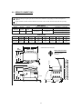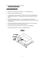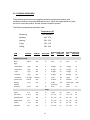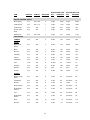
1
BCH-G
GAS CABINET BASED BRAISING PAN WITH
HEAVY DUTY HYDRAULIC TILT
INSTALLATION – OPERATION – MAINTENANCE
BLODGETT OVEN COMPANY
www.blodgett.com
44 Lakeside Avenue, Burlington, Vermont 05401 USA Telephone (800) 331-5842, (802) 860-3700 Fax: (802) 864-0183
1
S00067 Rev A (5/04)
IMPORTANT NOTES FOR INSTALLATION AND OPERATION
It is recommended that this manual be read thoroughly and that all instructions be
followed carefully. This manual should be retained for future reference.
This is the safety alert symbol. It is used to alert you to potential
personal injury hazards. Obey all safety messages that follow this
symbol to avoid possible injury or death.
FOR YOUR SAFETY: Do not store or use gasoline or other
flammable vapors or liquids in the vicinity of this or any other
appliance.
PURCHASER: Instructions to be followed in the event that the operator of this
appliance smells gas must be posted in a prominent location. This information
shall be obtained by consulting the local gas supplier.
The appliance area must be kept free and clear of combustibles.
Do not obstruct the flow of combustion and ventilation air.
Adequate clearances must be maintained for safe and proper operation.
WARNING: Improper installation, operation, adjustment, alteration,
service or maintenance can cause property damage, injury or death.
Read the installation, operating and maintenance instructions
thoroughly before installing, operating or servicing this equipment.
Do not attempt to operate this unit in the event of power failure.
Intended for commercial use only. Not for household use.
2
TABLE OF CONTENTS
DESCRIPTION
PAGE
1.0 Important Notes for Installation and Operation ........................................................ 2
2.0 Service Connections ................................................................................................ 4
3.0 Installation Instructions ............................................................................................. 5
4.0 Operating Instructions .............................................................................................. 8
5.0 Cleaning Instructions .............................................................................................. 11
6.0 Cooking Guidelines ................................................................................................ 12
7.0 Maintenance............................................................................................................. 16
8.0 Troubleshooting ..................................................................................................... 18
Material Safety Data Sheet ........................................................................................... 21
3
2.0 SERVICE CONNECTIONS
Supply gas through 3/4" pipe. A gas shut-off valve must be installed in supply piping convenient and adjacent to
appliance.
Unless otherwise specified, Field Wire Electrical Connection to be 120 Volts, 60 Hertz single phase with grounding
wire.
GAS SUPPLY
MODEL
BTU/HR.
kW/HR.
BCH-30G
80,000
23.4
Natural
Propane
29.3
6"-14"
[152-356mm]
11"-14"
[279-356mm]
BCH-40G
100,000
SUPPLY PRESSURE (W.C.)
EQUIPMENT CLEARANCE
LEFT
3.0" [76 mm]
RIGHT 3.0" [76 mm]
REAR 6.0" [152 mm]
DIMENSIONS
CAPACITY UNITS
30 gallons inches
BCH-30G
114 litres
mm
40 gallons inches
BCH-40G
152 litres
mm
MODEL
A
42.5
1079
44.0
1118
B
74.0
1880
74.0
1880
D
36.0
914
48.0
1219
E
14.0
356
19.0
483
F
33.5
851
43.5
1105
DIMENSIONS ARE IN INCHES [MM]
REAR FLANGED FOOT DETAIL
4 EQUALLY SPACED
Ø7/16" [11mm] HOLES
ON 3 [76] B.C.
24.25 [616]
3[76]
9.375 [238]
33 [838]
37 [940]
D
F
E
C
30.0
762
42.0
1067
18 [457]
28 [711]
40.5 [1029]
A
B
3[76]
7.5[191]
C
23.5 [597]
4
2.5 [64]
27 [686]
3.0 INSTALLATION INSTRUCTIONS
UNPACKING
Immediately after unpacking, check for possible shipping damage. If the tilting braising
pan is found to be damaged, save the packaging material and contact the carrier within
15 days of delivery.
Before installing, verify that the electrical service agrees with the specifications on the
rating plate located on the left side panel as you face the front of the braising pan. If the
supply and equipment requirements do not agree, contact your dealer or Blodgett
LOCATION
The installation location must allow adequate clearances for servicing and proper
operation.
An exhaust system and ventilation hood should be located directly above the appliance
to exhaust combustion gases generated by the unit.
Appliance is intended for use on noncombustible floors. Minimum clearance from
combustible and noncombustible floor construction, 3" (76 mm) on sides and 6" (152
mm) from back.
INSTALLATION CODES AND STANDARDS
Installation must conform with local codes, or in the absence of local codes, with the
National Fuel Gas Code, ANSI Z223.1/NFPA 54, or the Natural Gas and Propane
Installation Code, CSA B149.1, as applicable.
1. The appliance and its individual shut off valve must be disconnected from the gas
supply piping system during any pressure testing of that system at pressures in
excess of ½ psi (3.5 kPa).
2. The appliance must be isolated from the gas supply piping system by closing its
individual manual shut off valve during any pressure testing of the gas supply piping
system at test pressures equal to or less than ½ psi (3.5 kPa).
Electrical grounding must be provided in accordance with local codes, or in the absence
of local codes, with the National Electrical Code, ANSI/NFPA 70, or the Canadian
Electrical Code, CSA C22.2, as applicable.
ANSI/NFPA 96 - (latest edition), “Standard for Ventilation and Fire Protection of
Commercial Cooking Operations,” available from the National Fire Protection
Association, Batterymarch Park, Quincy, MA, USA, 02269.
5
3.0 INSTALLATION INSTRUCTIONS (Continued)
LEVELLING AND ANCHORING TILTING BRAISING PAN
1. Place tilting braising pan in the installation position.
2. Place a carpenter’s level on top of the braising pan and turn the adjustable feet to
level braising pan side-to-side and front-to-back.
3. Mark hole locations on the floor through the anchoring holes provided in the rear
flanged adjustable feet.
4. Remove tilting braising pan from installation position and drill holes in locations
marked on the floor. (See installation diagram on page 4.) Insert proper anchoring
devices (not supplied).
5. Place tilting braising pan back in the installation position.
6. Place carpenter’s level on top of braising pan and re-level side-to-side and front to
back.
7. Bolt and anchor tilting braising pan securely to the floor.
8. Seal bolts and flanged feet with silastic or equivalent compound.
GAS CONNECTIONS
All gas supply connections and any pipe joint compound used must be resistant to the
action of propane gases.
Connect gas supply to the appliance. The gas supply line must be at least equivalent of
3/4" iron pipe with an incoming pressure of 7" - 14" W.C. (Water Column) for natural gas
or 11" - 14" W.C. (Water Column) for propane gas. Make sure the pipes are clean and
free of obstructions, dirt and piping compound.
Codes require that a gas shutoff valve be installed in the gas line ahead of the tilting
braising pan. Natural gas and propane gas skillets are equipped with fixed orifices and
no adjustment is necessary. Gas burner manifold is set at 3.5" W.C. (Water Column) for
natural gas, and 10" W.C. (Water Column) for propane gas.
After piping has been checked for leaks, all piping receiving gas should be fully purged
to remove air.
WARNING: Never use an open flame to check for gas leaks.
Check all connections for leaks using soapy water before use.
6
NOTICE: If this equipment is being installed at over 2,000 feet altitude and was
not so specified on order, contact service department. Failure to install with
proper orifice sizing may void the warranty.
CAUTION: The pipe thread compound used when installing pipes
must be a type that is resistant to the action of liquified petroleum or
propane gases.
ELECTRICAL CONNECTIONS
WARNING: Do not connect the appliance to the electrical supply
until after the gas connection has been made.
WARNING: ELECTRICAL GROUNDING INSTRUCTIONS
This appliance is equipped with a three-prong (grounding) plug for
your protection against shock hazard and should be plugged directly
into a properly grounded three-prong receptacle. Do not cut or
remove the grounding prong from this plug. (120V units only).
The wiring compartment is located behind the control panel. For units operated on
electrical supply other than 120 volts, remove the wiring compartment cover and make
electrical connections per the wiring diagram located inside the control housing cover
panel. The braising pan must be grounded in accordance with requirements of the
National Electrical Code or applicable local code.
Replace wiring compartment cover.
7
4.0 OPERATING INSTRUCTIONS
WARNING: The tilting braising pan and its parts are hot. Use care
when operating, cleaning and servicing the tilting braising pan.
BEFORE FIRST USE
Using a non-corrosive, grease-dissolving commercial cleaner, clean the protective metal
oils from all surface parts and the interior of the tilting braising pan. Follow the cleaner
manufacturer’s directions. Rinse thoroughly and drain the pan. Wipe dry with a soft
clean cloth.
CONTROLS:
TILT SWITCH -
Push up to raise tilting braising pan; push down to
lower tilting braising pan.
POWER SWITCH -
Turns power on to the lift motor. Note: it is not
necessary to have the power on when using the
braising pan. Turn power on only when you intend to
operate the tilt feature. This will save energy as well as
prevent the motor from overheating.
AMBER LIGHT -
Will light when the power is turned on to the lift motor.
THERMOSTAT-
When turned on, will initiate the electronic ignition
system and maintain the set temperature Temperature
settings range from 100°F (40°C) to 450°F (230°C).
RED TEMPERATURE LIGHT - Will light when burners are supplying heat to the tilting
braising pan.
8
4.0 OPERATING INSTRUCTIONS (Continued)
START UP PROCEDURE
1. Open the manual gas shut-off valve located inside cabinet on left side when facing
the front of the unit.
2. Ensure that the skillet pan is in the down or horizontal position.
3. Set the thermostat dial to the desired setting. The red “TEMPERATURE” pilot will be
on until the desired setting has been reached.
4. The green “IGNITION” pilot should remain on with the “TEMPERATURE” pilot,
indicating normal ignition and operation. If the “IGNITION” pilot goes off while the
“TEMPERATURE” pilot remains on, this indicates that the system has failed to ignite
the burners. A five minute period of complete shut off is required before restarting;
5. When the skillet has reached the setting, both pilots will go off, indicating the unit has
reached the set temperature and that the burners are off. The unit will cycle on and
off to maintain the set temperature.
6. Turn the “THERMOSTAT” switch to “OFF” when the skillet is not in use and close the
manual gas shut-off valve.
WARNING: In the event of main burner ignition failure, a 5 minute purge
period must be observed prior to re-establishing ignition source.
DAILY SHUT DOWN PROCEDURE
1. To turn tilting braising pan of, turn THERMOSTAT dial to OFF.
2. To turn power to tilt motor OFF, turn power switch to OFF.
3. Close manual gas shut-off valve.
9
4.0 OPERATING INSTRUCTIONS (Continued)
TILTING THE BRAISING PAN
1. DO NOT try to tilt braising pan with lid down. Turn POWER switch on.
2. Make sure the receiving pan is in place.
3. To tilt braising pan, push and hold TILT SWITCH in the UP mode until desired pan
position has been reached. The braising pan will empty when raised to the top tilt
position.
4. When the braising pan is raised 5E or more, the gas supply will be turned off
automatically. The braising pan will not operate when the pan is not in the horizontal
or down position.
5. Food is poured through the removable strainer (Figure 2) into a food receiving pan
positioned under the lip of the pouring spout (Figure 2).
6. To lower braising pan, push and hold TILT SWITCH in the DOWN mode.
7. When tilting mechanism is not in use, turn POWER switch off.
FIGURE 2
10
5.0 CLEANING INSTRUCTIONS
WARNING: Disconnect the power supply to the appliance before
cleaning or servicing.
After each use, allow the tilting braising pan to cool before cleaning. Keep exposed
cleanable areas of the tilting braising pan clean at all times. Do not get water in
electrical box or on any electrical component.
1. Thoroughly wash pan, pouring spout, lid and exterior surfaces with mild detergent
and warm water. If necessary, soak pan to remove food that is stuck to pan surface.
Rinse thoroughly and wipe dry with a soft clean cloth.
2. Clean removable strainer and receiving pan support with mild detergent and warm
water. Rinse thoroughly and wipe dry with a soft clean cloth.
3. Clean around burner air mixer and orifice if lint has accumulated.
4. Visually assure carry-over ports are unobstructed.
11
6.0 COOKING GUIDELINES
The guidelines given below are suggested quantities, temperature settings, and
estimated numbers of orders per load and per hour. When two temperatures are given,
the first is to start the product, and the second to finish the product.
The following temperatures should be used:
Temperature (EF)
Simmering
200 Maximum
Sautéing
225 - 275
Searing
300 - 350
Frying
325 - 375
Grilling
350 - 450
BCH-30G PER LOAD
QTY
PORTIONS
BCH-40G PER LOAD
QTY
PORTIONS
12
2 lbs.
10
3 lbs.
15
225
5
50 eggs
50
75 eggs
75
1 egg
225
8
50 eggs
50
75 eggs
75
- Fried
1 egg
400
4
30 eggs
30
45 eggs
45
- Poached
1 egg
225
5
36 eggs
36
60 eggs
60
- Scrambled
1-1/2 eggs
300-200
1
18 gal.
720
28 gal.
1100
French Toast
3 slices
450
7
35 slices
12
50 slices
17
Regular
Oatmeal
½ cup
250
2
20 lbs.
(100 cups)
500
40 lbs. (200
cups)
1000
Pancakes
2 each
400
10
30 ea.
15
50 ea.
25
ITEM
PORTION
TEMP (F)
BATCH/HR
3 slices
350
- Boiled-Hard
1 egg
- Boiled-Soft
BREAKFAST FOODS
Bacon
Eggs
FISH
Clams
1 pt.
400
10
10 qts.
20
15 qts.
30
2 - 3 oz.
400
5
70 - 3 oz.
35
110 - 3 oz.
55
Haddock Fillet
4 oz.
400
4
60 - 4 oz.
60
90 - 4 oz.
90
Halibut Steak
5 oz.
450
3
60 - 4 oz.
60
90 - 4 oz.
90
1 - 1 lb.
350
4
20 - 1 lb.
20
30 - 1 lb.
30
5 oz.
450
3
50 - 5 oz.
50
75 - 5 oz.
75
Fish Cakes
Lobster
Swordfish
12
ITEM
PORTION
TEMP (F)
BATCH/HR
BCH-30G PER LOAD
QTY
PORTIONS
BCH-40G PER LOAD
QTY
PORTIONS
SAUCES, GRAVIES, SOUPS
Brown Gravy
1 oz.
350 - 200
2
18 gal.
2300
35 gal.
4500
Cream Sauce
2 oz.
250 - 175
1
18 gal.
1150
35 gal.
2250
Cream Soup
6 oz.
200
1
18 gal.
375
35 gal.
725
French Onion
Soup
6 oz.
225
1
18 gal.
350
35 gal.
700
Meat Sauce
4 oz.
350 - 200
1
18 gal.
575
35 gal.
1100
3 oz.
400
6
30 lbs.
125
45 lbs.
200
Beans, Wax,
Green
3 oz.
400
3
25 lbs.
125
50 lbs.
250
Beets
3 oz.
400
1
30 lbs.
125
60 lbs.
300
Broccoli
3 oz.
400
3
25 lbs.
125
40 lbs.
200
Cabbage
3 oz.
400
5
20 lbs.
80
30 lbs.
125
Carrots
3 oz.
400
2
35 lbs.
150
70 lbs.
300
Cauliflower
3 oz.
250
5
15 lbs.
75
25 lbs.
125
Corn
1 ear
400
8
50 ears
50
75 ears
75
Potatoes
3 oz.
400
2
40 lbs.
200
60 lbs.
300
Spinach
4 oz.
250
10
6 lbs.
25
9 lbs.
35
Turnips
4 oz.
400
2
20 lbs.
100
30 lbs.
150
Beans, French
Green
3 oz.
400
6
15 lbs.
60
22-1/2 lbs.
90
Lima Beans
3 oz.
250
4
15 lbs.
60
22-1/2 lbs.
90
Broccoli
3 oz.
400
8
12 lbs.
50
18 lbs.
75
Sliced Carrots
3 oz.
250
6
15 lbs.
60
22-1/2 lbs.
90
Small Whole
Carrots
3 oz.
250
3
15 lbs.
50
22-1/2 lbs.
90
Corn
3 oz.
250
18
15 lbs.
50
22-1/2 lbs.
90
Small Whole
Onions
3 oz.
250
7
15 lbs.
50
22-1/2 lbs.
90
Peas
3 oz.
400
10
15 lbs.
22-1/2 lbs.
110
Spinach
3 oz.
400
3
15 lbs.
22-1/2 lbs.
110
VEGETABLES
CANNED
FRESH
FROZEN
13
75
75
ITEM
PORTION
TEMP (F)
BATCH/HR
BCH-30G PER LOAD
QTY
PORTIONS
BCH-40G PER LOAD
QTY
PORTIONS
DESSERTS, PUDDINGS, SWEET SAUCES
Butterscotch
Sauce
1 oz.
200
1
18 gal.
2300
35 gal.
4500
Cherry Cobbler
3 oz.
200
1
18 gal.
750
35 gal.
1500
Chocolate
Sauce
1 oz.
200
1
18 gal.
2300
35 gal.
4500
Cornstarch
Pudding
4 oz.
200
1
18 gal.
575
35 gal.
1100
Fruit Gelatin
3 oz.
250
2
18 gal.
750
35 gal.
1500
3 slices
350
12
2 lbs.
10
3 lbs.
15
Amer. Chop
Suey
6 oz.
400 - 225
2
18 gal.
350
35 gal.
700
Beef Stew
8 oz.
300
-
18 gal.
280
35 gal.
560
Corned Beef
Hash
5 oz.
400
5
16 lbs.
50
25 lbs.
75
Cheeseburger
3 oz.
300
12
7 lbs.
35
10 lbs.
50
Hamburger
3 oz.
300
15
7 lbs.
35
10 lbs.
50
Meatballs
1 oz.
400-225
3
12-1/2 lbs.
65
18 lbs.
100
Pot Roast
2 oz.
350-200
120 lbs.
500
180 lbs.
750
Salisbury Steak
5 oz.
400
3
16 lbs.
50
24 lbs.
75
Sirloin Steak
6 oz.
400
5
15 lbs.
40
22-1/2 lbs.
60
Swiss Steak
4 oz.
300-200
1
25 lbs.
110
40 lbs.
160
2-1/4's
350
3
50 pieces
25
80 pieces
40
2 oz.
350-200
16 - 5 lbs.
200
24-5 lbs.
265
Grilled
2 oz.
300
8
22 lbs.
176
33 lbs.
264
Boiled
2 oz.
250
12
16 lbs.
128
25 lbs.
200
3 oz.
400
8
10 lbs.
50
15 lbs.
75
3 links
350
7
30 lbs.
120
45 lbs.
180
5 oz.
350
4
15 lbs.
50
25 lbs.
75
MEAT-POULTRY
Bacon
BEEF
CHICKEN
Pan Fried
Whole
FRANKFURTERS
PORK
Ham Steak
Sausage Links
Pork Chops
14
ITEM
PORTION
TEMP (F)
BATCH/HR
BCH-30G PER LOAD
QTY
PORTIONS
BCH-40G PER LOAD
QTY
PORTIONS
MEAT-POULTRY (continued)
TURKEY
Off Carcass
2 oz.
400-200
–
3 26-30 lbs.
200
4 26-30 lbs.
275
On Carcass
2 oz.
400-200
–
4 16-20 lbs.
175
6 16-20 lbs.
265
1 sandwich
400
8
35
sandwiches
35
50 sand.
50
Macaroni &
Cheese
8 oz.
200
2
18 gal.
300
35 gal.
525
Rice
4 oz.
350-225
1
20 lbs. raw
320
40 lbs. raw
650
Spaghetti
4 oz.
350-225
2
8 lbs. raw
200
12 lbs. raw
300
MISCELLANEOUS
Grilled Cheese
Sandwich
15
7.0 MAINTENANCE
NOTICE: Contact the factory, factory representative or local service company
to perform maintenance and repairs.
WARNING: The tilting braising pan and its parts are hot. Use care
when operating, cleaning and servicing the tilting braising pan.
WARNING: Disconnect the power supply to the appliance before
cleaning or servicing.
HYDRAULIC SYSTEM
SERVICE
Set up regular schedule for checking the oil temperature, hydraulic hoses and keeping
the equipment clean. A thick layer of dirt acts as an insulation and prevents the
hydraulic system from getting rid of heat.
The hydraulic system has been adjusted and tested at the factory and no further
adjustment should be needed. If the unit fails to operate properly, all service work must
be performed by a qualified service agent.
1. Hot oil in the Hydraulic System is one of the primary causes of poor operation.
When the tilt system is not in use turn POWER switch off.
2. Inspect hydraulic hoses for wear and aging.
3. Check that fluid levels are kept full.
4. To replace oil, fill through filler breather.
5. Use proper oil as specified by factory. TYPE: AWH32 or equivalent.
6. Check the cleanliness of the oil strainer inside the reservoir once per year. This item
can be washed in clean Varsol.
7. Change the breather filter once per year.
8. Change the oil once every two years.
16
ADJUSTMENTS AND CONTROLS:
ADJUST PAN SPEED
There are three controls available on this power unit. The first is an adjustable relief
valve mounted into the custom aluminum manifold block. The other two control the
linear speed of the actuator.
RELIEF VALVE:
The relief valve is located underneath an aluminum hexagon cover on the side of the
custom manifold block. This relief valve is factory set to 825 P.S.I. and locked and
should not be adjusted.
If adjustments are necessary, remove the hexagon cover which will give access to the
relief valve screw. With the pump running, and with a suitable flat blade style
screwdriver, rotate the screw clockwise to increase pressure, and counter-clockwise to
decrease pressure. While this operation is being carried out some oil will leak down the
threads of the adjusting screw.
To obtain the pressure required, a pressure gauge will have to be located in the circuit.
The best location is on the cylinder hose. To set the pressure, energize the solenoid to
extend the cylinder fully and thus “deadhead” the system. The pressure can be set as
indicated above. When adjustment is complete, replace the hexagon cover. This will
seal the relief valve area. The actual factory set pressure is noted on the label and
should not be exceeded as this affects the HP draw on the electric motor.
FLOW CONTROL:
There are two flow control valves mounted on the power unit and located on the solenoid
valve subplate. The flow control valves will restrict the capacity of oil passing through
them when the knurled knob is screwed in - in a clockwise direction. This action will
reduce the linear speed of the cylinder. Turning the flow control valve adjustment in the
opposite direction – counter-clockwise, will increase the speed of the cylinder. One flow
control valve (right side) will allow adjustment of the extension speed (travel speed
should be set at minimum 20 seconds), the other (left side) the retraction speed.
(Retraction speed should be set at minimum 10 seconds).
IMPORTANT:
It should be noted that if the cylinder speed is restricted by the flow control valves, the
balance of oil not delivered to the cylinder will go over the relief @ 825 P.S.I. which will
cause unwanted heat in the reservoir.
17
8.0 TROUBLESHOOTING
1) BURNERS DO NOT COME ON:
a) Gas supply to unit is “OFF”.
b) Manual shut off valve is “OFF”.
c) Thermostat is not turned “ON”.
d) Pan not in lowest position.
e) Ignition Module not functioning.
2) BURNERS PRODUCE CARBON DEPOSITS:
a) Wrong size orifices.
b) Burner air not adjusted properly.
c) Wrong gas supply.
d) Incorrect pressure at supply.
3) BRAISING PAN WILL NOT OPERATE (UP OR DOWN):
a) Motor power supply not “ON”.
b) Defective UP/DOWN switch.
c) SEE TROUBLESHOOTING - HYDRAULICS.
TROUBLESHOOTING - HYDRAULICS:
1) DIRTY OIL:
a) Components not properly cleaned after servicing.
b) Inadequate screening in fill pipe.
c) Air breather left off.
d) Filter dirty or ruptured.
2) FOAMING OIL:
a) Return of tank line not below fluid level.
b) Fluid contamination.
c) Suction leak to pump.
18
3) MOISTURE IN OIL:
a) Fill pipes left open.
b) Moisture in container used to replace oil in tank.
c) Extreme temperature differential.
4) OVERHEATING OF SYSTEM:
a) Continuous operation at relief setting.
b) Excessive slippage or internal leakage.
c) Fluid viscosity too high or low.
d) Hose I.D. too small causing high velocity.
e) Improper air circulation around reservoir.
f)
System relief valve set too high.
g) Power unit operating in direct sunlight or ambient temperature is too high.
5) PUMP MAKES EXCESSIVE NOISE:
a) Check for vacuum leaks in suction line.
b) Vacuum leak at pump shaft seal.
c) Check alignment with drive mechanism. Misalignment will cause wear and
subsequent high noise level operation.
d) Relief valve set too high.
e) Aeration of fluids in reservoir (return line above fluid level.)
f)
Worn cam ring, damaged gear, faulty bearing.
g) Reversed rotation.
h) Plugged lines.
i)
Oil viscosity too high or temperature too low.
j)
Loose or worn pump parts.
k) Pump housing bolts loose or not properly torqued.
19
6) SOLENOID VALVES:
a) Voltage too low.
b) Short circuit, open connection.
c) Wrong voltage.
d) Foreign matter in fluid causing valves to stick or plug.
20
Proper Shipping Name: Hydraulic System Fluid, Other Than Petroleum
WHMIS Hazard: Not Controlled
TDG Hazard Class: Non-Hazardous
Hazard Number: Not applicable
Chemical Family: Mixture
Completed By: J. Pajak
Telephone Number: 1-416-763-4691
Facsimile Number: 1-416-763-3167
DUNS Number: 20-167-2573
SECTION II - HAZARDOUS COMPONENTS
Material Description
CAS No.
Percent
Hazard
This product contains no known hazardous components under current OSHA, ACGIH,
WHMIS or the IDL regulations.
SECTION III - PHYSICAL DATA
Boiling Point (Degree Fahrenheit) :
Specific Gravity (Water = 1)
:
Vapour Pressure (mmHg)
:
Evaporation Rate (BuAcr = 1)
:
Vapour Density (Air = 1)
:
Percent Volatile
:
Soluble in Water
:
pH Neat
:
Appearance and Odour
:
>300
0.91
<1
<1
>1
Nil
Insoluble
Not Applicable
Slightly hazy amber liquid with a bland odour.
SECTION IV - FIRE AND EXPLOSION HAZARD DATA
Flash Point (Degrees Fahrenheit)
Method Used
LEL
UEL
NFPA Classifications, Health
Fire
Reactivity
:
:
:
:
:
:
:
520
C.O.C.
Not Determined
Not Determined
1
1
0
Extinguishing Methods
: Carbon dioxide, foam, dry chemical
Special Fire Fighting Instructions
: None required
Unusual Fire and Explosion Hazards: None
21
SECTION V - HEALTH HAZARD INFORMATION
Threshold Limit Value (TLV) and Permissible Exposure Limit (PEL): See Section II Hazardous Components
Primary Routes of Exposure - Eyes, skin, inhalation.
Chronic or Recurrent Effects: Unknown for this product.
Acute Effects:
Inhalation: No significant effects known.
Skin: May be a mild irritant on prolonged contact.
Eyes: Mild irritant
Ingestion: No significant effects known.
*** First Aid ***
Inhalation: Not applicable.
Skin: Wash with soap and water. Remove contaminated clothing and launder before
reusing.
Eye: Flush with water for 15 minutes. Consult physician.
Ingestion: Induce vomiting. Give liquids. Consult physician. Product contains fatty
acid ester.
Note to Physicians: No specific antidote known. Based on individual reactions of the
patient, the physician’s judgement should be used to control symptoms and clinical
conditions.
SECTION VI - REACTIVITY DATA
Stability: Stable [X], Unstable [ ]
Incompatibility (Materials to Avoid): Strong Oxidizers
Hazardous Decompostion Products: Thermal, Oxides of Carbon
Hazardous Polymerization: May Occur: [ ], Will Not Occur [X]
SECTION VII - SPILL OR LEAK PROCEDURES
Potential as a Pollutant: Not considered a pollutant if effective waste disposal methods
are utilized. Keep out of sewers and streams.
Spill, Leak or Release: Apply dry absorbent material and sweep up.
22
Waste Disposal: Follow pertinent regulations for disposal. It is the responsibility of the
product user to determine, at the time of disposal, whether a material containing the
product or derived from the product should be classified as a hazardous waste (40 CFR
261.20-24).
SECTION VIII - SPECIAL PROTECTION INFORMATION
Respiratory Protection: Not required.
Ventilation: General workplace ventilation is satisfactory
Protective Gloves: Rubber if skin is sensitive.
Eye Protection: Safety goggles or safety glasses with side shields.
Other Protective Equipment: Eye wash and safety shower recommended.
SECTION IX - SPECIAL PRECAUTIONS
Storage and Handling: Keep containers closed when not in use. Avoid contact with
strong oxidizers. Wash thoroughly after handling.
ADDITIONAL PRODUCT INFORMATION
Carcinogens as Defined By: NTP: None
IARC: None
OSHA: None
Cercla Reportable Quantity (Ibs.): None
RCRA Hazardous Waste Number: Not Applicable
CEPA: All components of this product are listed on the Domestic Substances List (DSL)
as encoded in the extract of the Canada Gazette, Part I.
SARA, Title III, Section 313: This product contains no toxic chemicals subject to the
reporting requirements of Section 313 of Title III of the Superfund Amendments and
Reauthorization Act of 1986 and 40 CFR part 372.
The information contained herein is based on data considered accurate. However, no
warranty is expressed or implied regarding the accuracy or the translation of this data or
the results to be obtained from the use thereof. Houghton Canada Inc. assumes no
responsibility for personal injury or damage to users or third parties caused by the
material. Such users assume all risks associated with
23